EP3642559B1 - An apparatus and a method for rolling weight deflection measurement - Google Patents
An apparatus and a method for rolling weight deflection measurement Download PDFInfo
- Publication number
- EP3642559B1 EP3642559B1 EP17735031.1A EP17735031A EP3642559B1 EP 3642559 B1 EP3642559 B1 EP 3642559B1 EP 17735031 A EP17735031 A EP 17735031A EP 3642559 B1 EP3642559 B1 EP 3642559B1
- Authority
- EP
- European Patent Office
- Prior art keywords
- sensor
- range
- inclination
- tan
- range sensors
- Prior art date
- Legal status (The legal status is an assumption and is not a legal conclusion. Google has not performed a legal analysis and makes no representation as to the accuracy of the status listed.)
- Active
Links
Images

Classifications
-
- G—PHYSICS
- G01—MEASURING; TESTING
- G01B—MEASURING LENGTH, THICKNESS OR SIMILAR LINEAR DIMENSIONS; MEASURING ANGLES; MEASURING AREAS; MEASURING IRREGULARITIES OF SURFACES OR CONTOURS
- G01B11/00—Measuring arrangements characterised by the use of optical techniques
- G01B11/24—Measuring arrangements characterised by the use of optical techniques for measuring contours or curvatures
- G01B11/245—Measuring arrangements characterised by the use of optical techniques for measuring contours or curvatures using a plurality of fixed, simultaneously operating transducers
-
- G—PHYSICS
- G01—MEASURING; TESTING
- G01B—MEASURING LENGTH, THICKNESS OR SIMILAR LINEAR DIMENSIONS; MEASURING ANGLES; MEASURING AREAS; MEASURING IRREGULARITIES OF SURFACES OR CONTOURS
- G01B11/00—Measuring arrangements characterised by the use of optical techniques
- G01B11/16—Measuring arrangements characterised by the use of optical techniques for measuring the deformation in a solid, e.g. optical strain gauge
-
- E—FIXED CONSTRUCTIONS
- E01—CONSTRUCTION OF ROADS, RAILWAYS, OR BRIDGES
- E01C—CONSTRUCTION OF, OR SURFACES FOR, ROADS, SPORTS GROUNDS, OR THE LIKE; MACHINES OR AUXILIARY TOOLS FOR CONSTRUCTION OR REPAIR
- E01C23/00—Auxiliary devices or arrangements for constructing, repairing, reconditioning, or taking-up road or like surfaces
- E01C23/01—Devices or auxiliary means for setting-out or checking the configuration of new surfacing, e.g. templates, screed or reference line supports; Applications of apparatus for measuring, indicating, or recording the surface configuration of existing surfacing, e.g. profilographs
-
- G—PHYSICS
- G01—MEASURING; TESTING
- G01M—TESTING STATIC OR DYNAMIC BALANCE OF MACHINES OR STRUCTURES; TESTING OF STRUCTURES OR APPARATUS, NOT OTHERWISE PROVIDED FOR
- G01M5/00—Investigating the elasticity of structures, e.g. deflection of bridges or air-craft wings
- G01M5/0041—Investigating the elasticity of structures, e.g. deflection of bridges or air-craft wings by determining deflection or stress
- G01M5/005—Investigating the elasticity of structures, e.g. deflection of bridges or air-craft wings by determining deflection or stress by means of external apparatus, e.g. test benches or portable test systems
- G01M5/0058—Investigating the elasticity of structures, e.g. deflection of bridges or air-craft wings by determining deflection or stress by means of external apparatus, e.g. test benches or portable test systems of elongated objects, e.g. pipes, masts, towers or railways
-
- E—FIXED CONSTRUCTIONS
- E01—CONSTRUCTION OF ROADS, RAILWAYS, OR BRIDGES
- E01C—CONSTRUCTION OF, OR SURFACES FOR, ROADS, SPORTS GROUNDS, OR THE LIKE; MACHINES OR AUXILIARY TOOLS FOR CONSTRUCTION OR REPAIR
- E01C23/00—Auxiliary devices or arrangements for constructing, repairing, reconditioning, or taking-up road or like surfaces
- E01C23/06—Devices or arrangements for working the finished surface; Devices for repairing or reconditioning the surface of damaged paving; Recycling in place or on the road
- E01C23/07—Apparatus combining measurement of the surface configuration of paving with application of material in proportion to the measured irregularities
-
- G—PHYSICS
- G01—MEASURING; TESTING
- G01B—MEASURING LENGTH, THICKNESS OR SIMILAR LINEAR DIMENSIONS; MEASURING ANGLES; MEASURING AREAS; MEASURING IRREGULARITIES OF SURFACES OR CONTOURS
- G01B11/00—Measuring arrangements characterised by the use of optical techniques
- G01B11/24—Measuring arrangements characterised by the use of optical techniques for measuring contours or curvatures
- G01B11/25—Measuring arrangements characterised by the use of optical techniques for measuring contours or curvatures by projecting a pattern, e.g. one or more lines, moiré fringes on the object
- G01B11/2518—Projection by scanning of the object
-
- G—PHYSICS
- G01—MEASURING; TESTING
- G01C—MEASURING DISTANCES, LEVELS OR BEARINGS; SURVEYING; NAVIGATION; GYROSCOPIC INSTRUMENTS; PHOTOGRAMMETRY OR VIDEOGRAMMETRY
- G01C7/00—Tracing profiles
- G01C7/02—Tracing profiles of land surfaces
- G01C7/04—Tracing profiles of land surfaces involving a vehicle which moves along the profile to be traced
-
- G—PHYSICS
- G01—MEASURING; TESTING
- G01M—TESTING STATIC OR DYNAMIC BALANCE OF MACHINES OR STRUCTURES; TESTING OF STRUCTURES OR APPARATUS, NOT OTHERWISE PROVIDED FOR
- G01M5/00—Investigating the elasticity of structures, e.g. deflection of bridges or air-craft wings
- G01M5/0091—Investigating the elasticity of structures, e.g. deflection of bridges or air-craft wings by using electromagnetic excitation or detection
Definitions
- the present invention relates to rolling weight deflection measurements, and in particular an apparatus for rolling weight deflection measurement comprising a rolling wheel to be moved along a measuring surface in a first direction a frame extending essentially along said measuring surface in said first direction, at least one carrier, and a number of spaced apart range sensors arranged on said at least one carrier and configured to measure a distance to said measuring surface at pavement locations passed by the apparatus, a first of said range sensors being arranged at a predetermined location with respect to said rolling wheel, and the remainder of the range sensors being arranged in spaced apart manner in line with said first range sensor in the first direction,
- Rolling weight deflectometers and their use are well established in surveying of pavements, such as road or airport runways covered with concrete or tarmac, for faults and defects.
- a rolling weight deflectometer comprises a heavy weight, e.g. 5,000 kg or more, supported by a wheel, which is rolled over the pavement at relatively high speed such as 100 km/h. The weight causes a localised depression basin in the pavement surface around the wheel. Because of the elastic properties of the pavement, the deflection basin moves along the pavement surface together with the rolling weight, leaving no permanent depression in the surface. The depth of the depression basin has been used as an indicator for the elasticity module of the pavement, in turn, indicating defects and faults in the pavement, in particular the deeper layers, which need further investigation. Due to the high speed, the use of a rolling weight deflectometer is an efficient way of surveying the pavement.
- One of the distance sensors is arranged above the point where the loaded wheel engages and deflects the pavement surface, whereas the others are arranged with equidistant spacing along the beam in front of the loaded wheel, i.e. leading as seen in the direction of motion when, during measurement, the rolling weight deflectometer is moved along the pavement.
- the actual deflection caused can be calculated quite precisely, using a suitable algorithm, e.g., the Harr algorithm as explained in US-A-5753808 and WO2013/185759 .
- US-A-4571695 discloses a rolling weight deflectometer with range sensors and an inclination sensor.
- the rolling weight deflectometer must have a substantial length.
- the spacing in prior art rolling weight deflectometers is about 3 meters, and the overall length of the rolling weight deflectometer including wheels and tow bar normally exceeds 10 meters.
- the prior art rolling weight deflectometers are therefore long and quite unhandy, considering that a towed rolling weight deflectometer, will have to be manoeuvred like any other trailer, including turning and reversing, when not running in a straight line during surveying.
- this object is achieved by an apparatus for rolling weight deflection measurement according to claim 1.
- the object is achieved by a method according to claim 6 for surveying a pavement using the rolling weight deflectometer.
- a first of said range sensors is arranged at a location corresponding to said rolling wheel, and the remainder of the range sensors being arranged in spaced apart manner preceding said first range sensor in the first direction.
- said inclination sensor comprises at least a pair of accelerometers. Due to their widespread use in e.g. smart phones accelerometers are readily available and incur only low costs as compared to e.g. a gyroscope.
- the range sensors and the inclination sensor provide input to a data processing means adapted to calculate a curvature parameter value of a depression basin formed by the apparatus in the measuring surface when the apparatus is moved along the measuring surface. Calculating a curvature parameter yields the possibility of better estimating the condition of the pavement, in particular the hidden lower layers.
- the number of range sensors is three. Using an inclination sensor, no more than three range sensors is needed. This in turn allows the overall length of the rolling weight deflectometer to be reduced as compared to the prior art rolling weight deflectometers, using four range sensors.
- Fig. 1 the upper part schematically shows a rolling weight deflectometer 11 according to the invention in a first position.
- the rolling weight deflectometer 11 is adapted to be moved, typically towed, in a first direction generally indicated with the arrow 13 along a test or measuring surface 12 formed by the pavement to be surveyed.
- the pavement could e.g. be a road or an airport runway covered with concrete or asphalt, which has to be surveyed for faults and defects.
- the rolling weight deflectometer comprises a weight.
- the weight acts on a load wheel 14.
- the rolling weight deflectometer is sometimes referred to as rolling wheel deflectometer.
- the abbreviation RWD is widely used.
- the load wheel 14 support is generally arranged at the trailing end of the rolling weight deflectometer 11 as defined by the motion in the first direction 13.
- the load wheel 14 is weighed down by a substantial mass so as to provide a down force on the pavement of e.g. 50 kN, 100 kN or 200 kN.
- This down force creates a deflection basin 5 around the load wheel 14 which propagates along the surface as the load wheel 14 moves.
- the depth of the deflection in the deflection basin 5 around the load wheel has been exaggerated, both in the upper and lower part of in Fig. 1 , but in particular in Fig. 2 .
- the actual deflection is in fact only in the micrometer range, typically in the range from 100 micrometers to 2000 micrometers, whereas the typical overall length of the rolling weight deflectometer 11 in the first direction would be about a few meters as will be explained below.
- the beam 6 may be a part of the overall frame of the rolling weight deflectometer 11.
- the beam 6 carries a number of range sensors 7, 8, 9, 10 directed towards the test surface, but the range sensors 7, 8, 9, 10 may also be supported otherwise.
- a laser alignment system 21 is preferably used to keep track of variations in the position of individual range sensors 7, 8, 9, 10 due to flexibility of the beam 6, variations in thermal expansion along the length thereof etc., as e.g. described in US-A-5753808 .
- the range sensors 7, 8, 9, 10 are preferably equidistant, i.e.
- the rolling weight deflectometer may be made shorter when, in accordance with the present invention, an inclination sensor 22 has been provided in a fixed relationship with the range sensors 7, 8, 9, 10, e.g. rigidly connected to the essentially horizontal beam 6 or the frame.
- the essentially horizontal beam 6 is to be understood as a beam which is essentially parallel to an arbitrary reference plane of the measuring surface. If the pavement to be surveyed goes up or downhill deviations from horizontal will be evident.
- the beam 6 is only essentially horizontal, as the very purpose of the inclination sensor 22 is to detect the very minute angular deviations of the beam 6 that inter alia stems from movements as the rolling weight deflectometer 11 moves over the measuring surface, i.e. the pavement being surveyed.
- a gyroscope is used as the inclination sensor 22.
- Gyroscopes come in many variations, such as classical spinning wheel gyroscopes, ring laser gyroscopes, fibre optic gyroscopes, and micro machined vibrating gyroscopes. The latter have become widely used in consumer electronics and now comes at reasonable prices.
- a pair of accelerometers could be used. Unlike the gyroscope which may be mounted at any suitable place in rigid connection with the range sensors 7, 8 ,9, 10 on the rolling weight deflectometer 11, e.g. on the beam 6, the accelerometers should be placed at spaced apart locations e.g. at either end of the rolling wheel deflectometer 11, e.g. at either end of the beam 6.
- the range sensors 7, 8, 9, 10 used in the present invention are preferably line scanners as disclosed in WO2013/185759 .
- a Gocator 2340 line scanner available from LMI Technologies, Inc. Line scanners of this type project a line onto the surface at an angle using a laser fanning out from a point source.
- the individual range sensors 7, 8, 9, 10 are preferably arranged to scan lines along the surface in a direction across the direction of movement. Repeating this scanning at suitable small intervals triggered e.g. by a tacho linked to the load wheel 14. Thus consecutive line scans will be made forming a virtual image of the surface with a given resolution depending inter alia on the resolution of the camera recording the undulations on the line and on the frequency with which the scan is triggered.
- the image is referred to as virtual because the resulting pixel values do not represent actual visual image data but distances.
- the distances need not be the vertical elevation of the sensor over the measuring area for the specific point but can, as seen from Fig. 2 , be measured at an angle depending on the inclination of the beam 6, i.e. the minute angular deviation from essentially horizontal of the beam 6, as measured using the inclination sensor 22.
- the rolling weight deflectometer 11 preferably further comprises a data processing means 15 such as a computer, which could, however, possibly also be located in a towing vehicle or at a remote location.
- a data processing means 15 such as a computer, which could, however, possibly also be located in a towing vehicle or at a remote location.
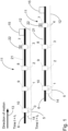
- FIG. 2 a schematic diagram of the measuring system is shown in conjunction with a deflected surveyed pavement with a measuring surface 12.
- Upper and lower parts of the diagram in Fig. 2 correspond to upper and lower parts of Fig. 1 , only for illustration purposes are the deflection in and the unevenness of the measuring surface even more exaggerated.
- the beam 6 is illustrated by the gray line.
- the four range sensors 7, 8, 9, 10 are located at positions 0, 1, 2, and 3.
- the range sensors 7, 8, 9, 10 are preferably laser range sensors, and for ease of explanation this will be assumed in the following, Accordingly, from the laser range sensors 7, 8, 9, 10 on the beam 6 four laser beams 17, 18, 19, 20 emanate in a direction towards the measuring surface 12, shown with a thick full line.
- an arbitrary reference plane 23 is defined, and shown with a thin full line.
- the un-deflected measurement surface 24 is shown, i.e. the surface as it would have been, was the weight of the rolling weight deflectometer not deflecting it.
- the laser beams 17, 18, 19 of the three of the four range sensors 7, 8, 9 at time t 1 (top) aim at the same location on the measurement surface as the laser beams 18, 19, 20 of range sensors 8, 9, 10 at time t 2 (bottom), allowing the comparison between deflected and un-deflected measurement surface.
- the basic principle also known as the Harr algorithm, as explained in US-A-5753808 and WO2013/185759 , assumes that at least four laser range sensors 7, 8, 9, 10 are attached equidistantly to the rigid beam.
- the laser range sensors record the distance z i from laser i to the ground simultaneously at times controlled by the user.
- the distance reading z i from laser i can be divided into four contributions:
- the objective is to measure each deflection d i independently, or at least some combination of deflections: as illustrated below, such combinations could be the so-called curvature or curvature-difference.
- the goal is to remove quantities from the observed data that do not relate to the deflections, such as the beam height h, the beam rotation ⁇ and the surface texture r i .
- a time t 2 is identified such that the measurements by lasers range sensors 10, 9, 8 at positions 0, 1 and 2 on the beam 6 hit the same place on the ground as the measurements by lasers 9, 8, 7 at positions 1, 2 and 3 on the beam 6 at time t 1 , see figure 2 .
- Equations (6) still contain both the beam height-difference ⁇ h and the beam angles ⁇ and ⁇ ' .
- the new and inventive algorithm constitutes an improvement over the classical Harr algorithm, in which the so-called curvature-difference is determined, as demonstrated below. This furthermore allows the rolling weight deflectometer 11 to be made shorter than prior art rolling weight deflectometers.
- Table 1 shows a summary of the differences between the new inventive curvature K and the classical curvature-difference ⁇ ⁇ from the Harr algorithm. Table 1 Summary of the differences between curvature and curvature-difference. Quantity Symbol Definition Measured by Curvature ⁇ i d i - 2d i +1 + d i +2 3 lasers, 1 gyroscope Curvature-difference ⁇ ⁇ i d i - 3 d i +1 + 3 d i +2 - d i +3 4 lasers
- the measurement system can determine the curvature using only three laser range sensors, and the curvature-difference using only four laser range sensors it can be expanded with more equidistantly-spaced lasers than the three/four considered in the example above. For each new laser added, both a new curvature and curvature-difference can be formed.
- Equations (18) still contain both the beam heights and the beam angles.
- the rolling wheel deflectometer 11 by reducing the length of the rolling wheel deflectometer 11, it becomes easier to provide a beam 6 or carrier for the laser range sensors which is not prone to undesired flexing and deformation, in turn obviating the need for the laser alignment system 21. It may even be possible not to use a beam 6 as a carrier as such, but instead mount the carrier(s) for the laser range sensors 7, 8, 9, 10 directly on the frame of the rolling weight deflectometer 11, or even use the frame itself as the carrier.
Landscapes
- Physics & Mathematics (AREA)
- General Physics & Mathematics (AREA)
- Engineering & Computer Science (AREA)
- Architecture (AREA)
- Civil Engineering (AREA)
- Structural Engineering (AREA)
- Aviation & Aerospace Engineering (AREA)
- Length Measuring Devices With Unspecified Measuring Means (AREA)
- Length Measuring Devices By Optical Means (AREA)
Description
- The present invention relates to rolling weight deflection measurements, and in particular an apparatus for rolling weight deflection measurement comprising a rolling wheel to be moved along a measuring surface in a first direction a frame extending essentially along said measuring surface in said first direction, at least one carrier, and a number of spaced apart range sensors arranged on said at least one carrier and configured to measure a distance to said measuring surface at pavement locations passed by the apparatus, a first of said range sensors being arranged at a predetermined location with respect to said rolling wheel, and the remainder of the range sensors being arranged in spaced apart manner in line with said first range sensor in the first direction,
- Rolling weight deflectometers and their use are well established in surveying of pavements, such as road or airport runways covered with concrete or tarmac, for faults and defects. A rolling weight deflectometer comprises a heavy weight, e.g. 5,000 kg or more, supported by a wheel, which is rolled over the pavement at relatively high speed such as 100 km/h. The weight causes a localised depression basin in the pavement surface around the wheel. Because of the elastic properties of the pavement, the deflection basin moves along the pavement surface together with the rolling weight, leaving no permanent depression in the surface. The depth of the depression basin has been used as an indicator for the elasticity module of the pavement, in turn, indicating defects and faults in the pavement, in particular the deeper layers, which need further investigation. Due to the high speed, the use of a rolling weight deflectometer is an efficient way of surveying the pavement.
- However, as explained in e.g.
US-A-5753808 ,WO2013/185759 or the article 'Rolling Weight Deflectometer with Thermal and Vibration Bending Compensation' Johnson, R.F. et al, TRANSPORTATION RESEARCH RECORD 1540, 1996, the deflection caused in the pavement is rather minute, e.g. in the magnitude of 100 micrometers, compared to the general surface roughness of the pavement, and it is thus not an easy task to measure at 100 km/h. As explained inUS-A-5753808 andWO2013/185759 , the traditional rolling weight deflectometer uses a number of distance sensors, e.g. four, arranged with equidistant spacing along a horizontal beam and measuring the distance downwardly to the pavement. One of the distance sensors is arranged above the point where the loaded wheel engages and deflects the pavement surface, whereas the others are arranged with equidistant spacing along the beam in front of the loaded wheel, i.e. leading as seen in the direction of motion when, during measurement, the rolling weight deflectometer is moved along the pavement. When comparing measuring data from all sensors in two subsequent situations, namely when the loaded wheel has moved exactly one sensor-spacing distance, that is from a first position to a second position corresponding exactly to the position where the preceding range sensor was when the loaded wheel was in the first position, the actual deflection caused can be calculated quite precisely, using a suitable algorithm, e.g., the Harr algorithm as explained inUS-A-5753808 andWO2013/185759 . - For calculating the deflection using the Harr algorithm, however, the assumption is made that the spacing between the range sensors is so long that all three leading sensors are outside the deflection basin, allowing the geometry of the undeflected pavement surface to be determined.
-
US-A-4571695 discloses a rolling weight deflectometer with range sensors and an inclination sensor. - However, with equidistant spacing of the range sensors and a spacing between them sufficient for the assumption of the three leading sensors to be outside of the basin to hold true for practical purposes, the rolling weight deflectometer must have a substantial length. In practice, the spacing in prior art rolling weight deflectometers is about 3 meters, and the overall length of the rolling weight deflectometer including wheels and tow bar normally exceeds 10 meters. The prior art rolling weight deflectometers are therefore long and quite unhandy, considering that a towed rolling weight deflectometer, will have to be manoeuvred like any other trailer, including turning and reversing, when not running in a straight line during surveying.
- Based on this prior art it is the object to provide a rolling weight deflectometer which does not suffer from the above drawbacks.
- According to a first aspect of the present invention this object is achieved by an apparatus for rolling weight deflection measurement according to
claim 1. - By incorporating the inclination sensor it becomes possible to calculate a curvature parameter value of the depression basin, which is an improvement compared to the quantity that is calculated using the traditional Harr algorithm mentioned above. This, in turn, allows more knowledge to be gained about the layers below the surface. Furthermore, combined with the realization that absolute deflections are not a requirement for interpretation and modelling of the pavement condition, it allows that the rolling weight deflectometer can be made shorter than the prior art rolling weight deflectometers.
- Thus, according to the second aspect of the invention, the object is achieved by a method according to
claim 6 for surveying a pavement using the rolling weight deflectometer. - According to a first preferred embodiment of the first aspect of the invention, a first of said range sensors is arranged at a location corresponding to said rolling wheel, and the remainder of the range sensors being arranged in spaced apart manner preceding said first range sensor in the first direction.
- This is the traditional way of arranging the sensors, and it would therefore make it easy to implement the present invention in existing rolling weight deflectometer constructions or even retrofit rolling weight deflectometers with the present invention.
- According to a preferred embodiment of the first aspect of the invention, said inclination sensor comprises at least a pair of accelerometers. Due to their widespread use in e.g. smart phones accelerometers are readily available and incur only low costs as compared to e.g. a gyroscope.
- According to a further preferred embodiment, the range sensors and the inclination sensor provide input to a data processing means adapted to calculate a curvature parameter value of a depression basin formed by the apparatus in the measuring surface when the apparatus is moved along the measuring surface. Calculating a curvature parameter yields the possibility of better estimating the condition of the pavement, in particular the hidden lower layers.
- According to another preferred embodiment, the number of range sensors is three. Using an inclination sensor, no more than three range sensors is needed. This in turn allows the overall length of the rolling weight deflectometer to be reduced as compared to the prior art rolling weight deflectometers, using four range sensors.
- According to the invention the curvature parameter is the value K calculated using the formula: κi = di-2d i+1 + d i+2 where di is the deflection measured with the i'th range sensor, d i+1 is the deflection measured with the (i+1)'th range sensor, and d i+2 is the deflection measured with the (i+2)'th range sensor. This has the advantage that it yields information based on only three range sensors. Accordingly, this reduces the necessary length of the rolling weight deflectometer, because only two range sensors need to be located outside of the deflection basin.
- The invention will now be described in greater detail based on nonlimiting exemplary embodiments and with reference to the drawing, on which:
-
Fig. 1 schematically shows a rolling weight deflectometer according to the invention, -
Fig. 2 schematically shows the deflection of a pavement and the measurements performed, and -
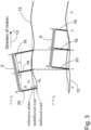
Fig. 3 schematically shows the deflection of a pavement and the measurements performed using a shortened rolling weight deflectometer according to the invention. - Turning first to
Fig. 1 , the upper part schematically shows arolling weight deflectometer 11 according to the invention in a first position. Therolling weight deflectometer 11 is adapted to be moved, typically towed, in a first direction generally indicated with thearrow 13 along a test or measuringsurface 12 formed by the pavement to be surveyed. The pavement could e.g. be a road or an airport runway covered with concrete or asphalt, which has to be surveyed for faults and defects. As the name suggests, the rolling weight deflectometer comprises a weight. The weight acts on aload wheel 14. For that reason, the rolling weight deflectometer is sometimes referred to as rolling wheel deflectometer. In either case, the abbreviation RWD is widely used. Theload wheel 14 support is generally arranged at the trailing end of therolling weight deflectometer 11 as defined by the motion in thefirst direction 13. Theload wheel 14 is weighed down by a substantial mass so as to provide a down force on the pavement of e.g. 50 kN, 100 kN or 200 kN. This down force creates adeflection basin 5 around theload wheel 14 which propagates along the surface as theload wheel 14 moves. For illustration purposes, the depth of the deflection in thedeflection basin 5 around the load wheel has been exaggerated, both in the upper and lower part of inFig. 1 , but in particular inFig. 2 . The actual deflection is in fact only in the micrometer range, typically in the range from 100 micrometers to 2000 micrometers, whereas the typical overall length of therolling weight deflectometer 11 in the first direction would be about a few meters as will be explained below. - Along the length of the
rolling weight deflectometer 11 runs a carrier in the form of an essentiallyhorizontal beam 6. Thebeam 6 may be a part of the overall frame of therolling weight deflectometer 11. Preferably thebeam 6 carries a number ofrange sensors range sensors laser alignment system 21 is preferably used to keep track of variations in the position ofindividual range sensors beam 6, variations in thermal expansion along the length thereof etc., as e.g. described inUS-A-5753808 . Therange sensors range sensors inclination sensor 22 has been provided in a fixed relationship with therange sensors horizontal beam 6 or the frame. In this respect it should be noted that the essentiallyhorizontal beam 6 is to be understood as a beam which is essentially parallel to an arbitrary reference plane of the measuring surface. If the pavement to be surveyed goes up or downhill deviations from horizontal will be evident. Furthermore, thebeam 6 is only essentially horizontal, as the very purpose of theinclination sensor 22 is to detect the very minute angular deviations of thebeam 6 that inter alia stems from movements as therolling weight deflectometer 11 moves over the measuring surface, i.e. the pavement being surveyed. - Preferably, a gyroscope is used as the
inclination sensor 22. Gyroscopes come in many variations, such as classical spinning wheel gyroscopes, ring laser gyroscopes, fibre optic gyroscopes, and micro machined vibrating gyroscopes. The latter have become widely used in consumer electronics and now comes at reasonable prices. Alternatively, a pair of accelerometers could be used. Unlike the gyroscope which may be mounted at any suitable place in rigid connection with therange sensors weight deflectometer 11, e.g. on thebeam 6, the accelerometers should be placed at spaced apart locations e.g. at either end of therolling wheel deflectometer 11, e.g. at either end of thebeam 6. - The
range sensors WO2013/185759 . Currently preferred is a Gocator 2340 line scanner, available from LMI Technologies, Inc. Line scanners of this type project a line onto the surface at an angle using a laser fanning out from a point source. - The
individual range sensors load wheel 14. Thus consecutive line scans will be made forming a virtual image of the surface with a given resolution depending inter alia on the resolution of the camera recording the undulations on the line and on the frequency with which the scan is triggered. The image is referred to as virtual because the resulting pixel values do not represent actual visual image data but distances. The distances need not be the vertical elevation of the sensor over the measuring area for the specific point but can, as seen fromFig. 2 , be measured at an angle depending on the inclination of thebeam 6, i.e. the minute angular deviation from essentially horizontal of thebeam 6, as measured using theinclination sensor 22. - It should be noted that the above method of matching subsequent distance measurements with one and the same location as disclosed in
WO2013/185759 is only one way of doing so, and that the use of aninclination sensor 22 according to the present invention is per se independent of the way the matching is done. - The rolling
weight deflectometer 11 preferably further comprises a data processing means 15 such as a computer, which could, however, possibly also be located in a towing vehicle or at a remote location. - Turning now to
Fig. 2 , a schematic diagram of the measuring system is shown in conjunction with a deflected surveyed pavement with a measuringsurface 12. Upper and lower parts of the diagram inFig. 2 correspond to upper and lower parts ofFig. 1 , only for illustration purposes are the deflection in and the unevenness of the measuring surface even more exaggerated. - Thus, in
fig. 2 thebeam 6 is illustrated by the gray line. On the beam the fourrange sensors positions range sensors laser range sensors beam 6 fourlaser beams surface 12, shown with a thick full line. For the purpose of explaining the algorithms involved in the measurement an arbitrary reference plane 23 is defined, and shown with a thin full line. Furthermore, using a thick dashed line the un-deflected measurement surface 24 is shown, i.e. the surface as it would have been, was the weight of the rolling weight deflectometer not deflecting it. - As can be seen, the
laser beams range sensors laser beams range sensors - The basic principle, also known as the Harr algorithm, as explained in
US-A-5753808 andWO2013/185759 , assumes that at least fourlaser range sensors - (1) h, the distance from
laser range sensor 10 atposition 0 to the arbitrary reference plane 23. - (2) ai=i Ltanθ, the distance to a plane intersecting
laser range sensor 10 atposition 0 and which is parallel to the reference plane 23. L is the distance between two neighbouringlaser range sensors beam 6 and θ is the angle between thebeam 6 and the reference plane 23. - (3) ri , the distance from the reference plane to the un-deflected road surface due to texture of the measuring
surface 12, i.e. the unevenness of the measuringsurface 12 itself. - (4) di, the distance from the un-deflected surface to the deflected surface due to deflection from the weight of the rolling
weight deflectometer 11. - The objective is to measure each deflection di independently, or at least some combination of deflections: as illustrated below, such combinations could be the so-called curvature or curvature-difference. In other words, the goal is to remove quantities from the observed data that do not relate to the deflections, such as the beam height h, the beam rotation θ and the surface texture ri .
- The equations relating the four laser range sensor measurements and their contributions at time t 1 are

- Using image correlation, a time t 2 is identified such that the measurements by lasers range
sensors positions beam 6 hit the same place on the ground as the measurements bylasers positions beam 6 at time t 1, seefigure 2 . At time t 2, we denote the time-dependent variables [zi,h,θ] with a prime and the equations are
- Note how the recording by laser i at time t 1 and t 2 involves the texture at location i and i+1, respectively. We have assumed that the shape of the deflection basin does not change between t 1 and t 2 such that

- The texture ri can be eliminated by subtracting the recording from laser i+1 at time t 1 from that of laser i at time t 2

- If we define a new quantity called the deflection-difference


- Equations (6) still contain both the beam height-difference Δh and the beam angles θ and θ'. Δh can be eliminated by subtracting (6)b from (6)a and (6)c from (6)
b 
- Inspired in part by numerical finite difference calculus, we introduce a new quantity called the curvature


- We assume that the angles are small, θ≪1 and θ'≪1, and remind that a Taylor Series expansion of the Tangent function around zero reveals that a linearization is a good approximation, tanx=x+O(x 3), and thus


- This is the new and inventive algorithm relating a curvature of a depression basin to the measurements from only three laser range sensors and a gyroscope. The new and inventive algorithm constitutes an improvement over the classical Harr algorithm, in which the so-called curvature-difference is determined, as demonstrated below. This furthermore allows the rolling
weight deflectometer 11 to be made shorter than prior art rolling weight deflectometers. - To highlight the difference to the classical Harr algorithm, we now give a short description of it. In our terminology, the classical Harr algorithm measures a quantity called the curvature difference

- We then recover the classical Harr algorithm by subtracting (9)b from (9)a to eliminate the beam angle-
difference 

- This is the classical Harr algorithm relating the curvature-difference of a deflection basin to the measurements from four lasers.
- Table 1 below shows a summary of the differences between the new inventive curvature K and the classical curvature-difference Δκ from the Harr algorithm.
Table 1 Summary of the differences between curvature and curvature-difference. Quantity Symbol Definition Measured by Curvature κi di - 2d i+1 + d i+23 lasers, 1 gyroscope Curvature-difference Δκi di - 3d i+1 + 3d i+2 - d i+34 lasers - We note that despite the fact that the measurement system can determine the curvature using only three laser range sensors, and the curvature-difference using only four laser range sensors it can be expanded with more equidistantly-spaced lasers than the three/four considered in the example above. For each new laser added, both a new curvature and curvature-difference can be formed. For instance, with a fifth laser, we can form three curvatures: κ 0=d 0-2d 1+d 2, κ 1=d 1 -2d 2 +d 3 and κ 2 =d 2 -2d 3 +d 4, and two curvature-differences: Δκ 0 =d 0-3d 1 +3d 2 -d 3 and Δκ 1 =d 1-3d 2+3d 3-d 4.
- So in pursuit of the object of the present invention it has been realized that by deviating from the classic Harr algorithm and not relying solely on distance measurements, it becomes possible to not only make a substantially shorter rolling weight deflectometer than those of the prior art, but also to gain additional knowledge about the pavement, in particular the sub-surface layers.
- In particular, as can be understood from table 1, the inventors have realized that using an inclination sensor as in the above, it will be possible to reduce the length of the
rolling wheel deflectometer 11 as one laser range sensor 7 can be omitted. - Thus, referring now to
Fig. 3 with the new curvature algorithm only three range sensors, e.g.laser range sensors inclination sensor 22, e.g. a gyroscope, are needed. Using onlylaser range sensors 

- Again, the texture ri can be eliminated by subtracting the recording from laser i+1 at time t 1 from that of laser i at time t 2

- Equations (17) can be rearranged as

- Equations (18) still contain both the beam heights and the beam angles. The beam heights can be eliminated by subtracting (18)b from (18)a

- When, as indicated above, the curvature is defined as


- Assuming still that the angles are small, θ ≪ 1 and θ' ≪ 1, and reminding that a Taylor Series expansion of the Tangent function around zero reveals that a linearization is a good approximation, tanx = x + 0(x 3), thus


- This is the novel algorithm relating a curvature to the distance measurements from three range sensors and one inclination sensor. As is readily derivable form
Fig. 3 this allows shortening the length of the rollingweight deflectometer 11 with an amount corresponding to the distance between the two laser range sensors, viz. the distance from thelaser range sensor 8 infig. 1 to the now omitted laser range sensor 7. - Furthermore, by reducing the length of the
rolling wheel deflectometer 11, it becomes easier to provide abeam 6 or carrier for the laser range sensors which is not prone to undesired flexing and deformation, in turn obviating the need for thelaser alignment system 21. It may even be possible not to use abeam 6 as a carrier as such, but instead mount the carrier(s) for thelaser range sensors weight deflectometer 11, or even use the frame itself as the carrier.
Claims (7)
- An apparatus (11) for rolling weight deflection measurement comprising a rolling wheel (14) to be moved along a measuring surface (12) in a first direction (13)a frame extending essentially along said measuring surface in said first direction (13),at least one carrier (6),a number of spaced apart range sensors (7, 8, 9, 10) arranged on said at least one carrier (6) and configured to measure a distance to said measuring surface at pavement locations passed by the apparatus (11), a first of said range sensors (10) being arranged at a predetermined location with respect to said rolling wheel (14), and the remainder of the range sensors (7, 8, 9) being arranged in spaced apart manner in line with said first range sensor (10) in the first direction,at least one inclination sensor (22) configured to measure at least a change in inclination of said at least one carrier (6),and a data processing means (15),characterized in that the data processing means (15) isadapted to calculate the curvature of a depression basin (5) formed by the apparatus (11) in the measuring surface (12) when the apparatus (11) is moved along the measuring surface (12), where the calculating is based on said measured distances and corresponding inclination measurements from said at least one inclination sensor to yield a curvature parameter of the depression basin (5), the curvature parameter being a value κ calculated using the formula:
 wheredi is the deflection measured with the i'th range sensor and the at least one inclination sensor (22),d i+1 is the deflection measured with the (i+1)'th range sensor and the at least one inclination sensor (22),d i+2 is the deflection measured with the (i+2)'th range sensor and the at least one inclination sensor (22).
 - An apparatus (11) according to claim 1, wherein said first of said range sensors (10) is arranged at a location corresponding to said rolling wheel (14), and the remainder of the range sensors (7, 8, 9) are arranged in a spaced part manner preceding or succeeding said first range sensor in the first direction.
- An apparatus (11) according to any one of the preceding claims wherein said inclination sensor (22) comprises at least a pair of accelerometers.
- An apparatus (11) according to any one of claims 1 or 2, wherein the at least one inclination sensor (22) is a fibre optic gyroscope.
- An apparatus according to any one of the preceding claims, wherein the number of range sensors is three.
- A method for surveying a pavement using an apparatus (11) according to claim 1, characterized in thatusing said number of range sensors (7, 8, 9, 10), a corresponding number of sequential distance measurements are made over time as the rolling weight deflectometer (11) is moved along said measuring surface,using said at least one inclination sensor (22) a sequence of inclination measurements are made over time as the apparatus (11) is moved along said measuring surface (12),comparing distance measurements for said passed locations, andcalculating based on said distance measurements and corresponding inclination measurements a curvature parameter of the depression basin (5).
- A method according to claim 6, wherein the curvature parameter is a value K calculated using the formula:
 di is the deflection measured with the i'th range sensor and the at least one inclination sensor (22),d i+1 is the deflection measured with the (i+1)'th range sensor and the at least one inclination sensor (22),d i+2 is the deflection measured with the (i+2)'th range sensor and the at least one inclination sensor (22).
Applications Claiming Priority (1)
| Application Number | Priority Date | Filing Date | Title |
|---|---|---|---|
| PCT/EP2017/065437 WO2018233838A1 (en) | 2017-06-22 | 2017-06-22 | APPARATUS AND METHOD FOR MEASURING WHEEL DAMAGE OF ROLLING MATERIAL |
Publications (3)
| Publication Number | Publication Date |
|---|---|
| EP3642559A1 EP3642559A1 (en) | 2020-04-29 |
| EP3642559B1 true EP3642559B1 (en) | 2025-02-19 |
| EP3642559C0 EP3642559C0 (en) | 2025-02-19 |
Family
ID=59276705
Family Applications (1)
| Application Number | Title | Priority Date | Filing Date |
|---|---|---|---|
| EP17735031.1A Active EP3642559B1 (en) | 2017-06-22 | 2017-06-22 | An apparatus and a method for rolling weight deflection measurement |
Country Status (4)
| Country | Link |
|---|---|
| US (1) | US11506481B2 (en) |
| EP (1) | EP3642559B1 (en) |
| ES (1) | ES3024661T3 (en) |
| WO (1) | WO2018233838A1 (en) |
Families Citing this family (8)
| Publication number | Priority date | Publication date | Assignee | Title |
|---|---|---|---|---|
| CN110373980A (en) * | 2019-07-31 | 2019-10-25 | 湖北文理学院 | The evaluating apparatus and method of binocular reconfiguration technique test road surface three-dimensional appearance precision |
| CN111287057B (en) * | 2020-03-18 | 2021-09-17 | 河南交院工程技术集团有限公司 | Deflection beam for measuring deflection value and road deflection value measuring device |
| CN111964638A (en) * | 2020-06-30 | 2020-11-20 | 同恩(上海)工程技术有限公司 | Deflection monitoring method and system based on fitting inversion mode |
| CN113916145B (en) * | 2021-10-15 | 2024-09-03 | 新疆阿尔金山建设工程有限公司 | A building steel structure deflection testing system and method |
| CN114481769B (en) | 2022-02-08 | 2022-11-08 | 交通运输部公路科学研究所 | A laser type high-speed deflection tester deflection calibration device and method |
| CN115182221B (en) * | 2022-08-03 | 2024-03-15 | 洛阳理工学院 | Full-automatic roadbed and pavement rebound deflection tester and test method |
| CN116429003B (en) * | 2023-04-03 | 2025-08-01 | 大连理工大学宁波研究院 | Monocular vision-based real-time measurement method and device for structural deformation of bending prevention device |
| CN116481448A (en) * | 2023-04-07 | 2023-07-25 | 河海大学 | A deflection monitoring method of airport assembly cement concrete pavement |
Family Cites Families (8)
| Publication number | Priority date | Publication date | Assignee | Title |
|---|---|---|---|---|
| US4571695A (en) * | 1982-07-09 | 1986-02-18 | Purdue Research Foundation | Non-contact road profilometer and deflection meter |
| US5753808A (en) | 1995-09-11 | 1998-05-19 | Quest Integrated, Inc. | Self-compensating rolling weight deflectometer |
| GB2486377B (en) * | 2009-10-16 | 2017-06-14 | Dynatest Int As | Triangulation of pavement deflections using more than four sensors |
| CN202559215U (en) * | 2012-01-06 | 2012-11-28 | 北京市路兴公路新技术有限公司 | Rapid detection device for pavement deflection |
| EP2861802B1 (en) | 2012-06-14 | 2022-11-02 | Ramböll Sweden AB | Rolling wheel deflectometer |
| CN103452032B (en) * | 2013-09-26 | 2015-06-24 | 武汉武大卓越科技有限责任公司 | Dynamic deflection obtaining method based on angles |
| US9834207B2 (en) * | 2014-04-15 | 2017-12-05 | GM Global Technology Operations LLC | Method and system for detecting, tracking and estimating stationary roadside objects |
| AU2014398251B2 (en) * | 2014-06-17 | 2017-09-14 | Halliburton Energy Services, Inc. | Reluctance sensor for measuring a magnetizable structure in a subterranean environment |
-
2017
- 2017-06-22 EP EP17735031.1A patent/EP3642559B1/en active Active
- 2017-06-22 WO PCT/EP2017/065437 patent/WO2018233838A1/en not_active Ceased
- 2017-06-22 ES ES17735031T patent/ES3024661T3/en active Active
- 2017-06-22 US US16/626,109 patent/US11506481B2/en active Active
Also Published As
| Publication number | Publication date |
|---|---|
| ES3024661T3 (en) | 2025-06-05 |
| US11506481B2 (en) | 2022-11-22 |
| US20200217646A1 (en) | 2020-07-09 |
| EP3642559C0 (en) | 2025-02-19 |
| EP3642559A1 (en) | 2020-04-29 |
| WO2018233838A1 (en) | 2018-12-27 |
Similar Documents
| Publication | Publication Date | Title |
|---|---|---|
| EP3642559B1 (en) | An apparatus and a method for rolling weight deflection measurement | |
| US9448148B2 (en) | Rolling weight deflectometer | |
| US9417154B2 (en) | Monitoring a response of a bridge based on a position of a vehicle crossing the bridge | |
| CN106092056B (en) | A kind of vehicle-mounted dynamic monitoring method of high-speed railway bridge foundation settlement deformation | |
| AU2012382625B2 (en) | Rolling wheel deflectometer | |
| US20140071269A1 (en) | Reference Measurement System for Rail Applications | |
| KR101128835B1 (en) | Measuring Apparatus for Height and stagger of trolley line using Line Scan Camera and Method thereof | |
| EP1285225A1 (en) | Apparatus for monitoring the rails of a railway or tramway line | |
| CN113701678B (en) | Road surface flatness detection method based on line scanning three-dimension | |
| US20220266881A1 (en) | Method and measuring vehicle for determining an actual position of a track | |
| JP4371406B2 (en) | Orbit measurement system and orbit measurement method | |
| CN114046789A (en) | Rail detection method based on collaborative measurement of rail inspection trolley navigation IMU | |
| RU2230849C2 (en) | Track machine | |
| KR100256324B1 (en) | Method and apparatus for measuring cross sectional dimensions of sectional steel | |
| CN103644888A (en) | Inertial reference measurement method for detecting bridge deformation | |
| US20240295086A1 (en) | Method of accurately measuring the topography of surfaces in civil engineering and a device for carrying out this method | |
| US20150211835A1 (en) | Method for compensating measurement errors due to thermally induced structural deformations in a coordinate measurement machine | |
| Briggs et al. | A comparison of the rolling weight deflectometer with the falling weight deflectometer | |
| US4752695A (en) | Planarity detection method for a moving rolled strip employing side edge detection with respect to a reference surface | |
| RU2256575C1 (en) | Method of and device for measuring geometry of track | |
| Wildi et al. | A multisensor platform for kinematic track surveying | |
| JP4444531B2 (en) | Simple inspection vehicle and calibration method thereof | |
| RU2726256C1 (en) | Method of constructing three-dimensional model of terrain along railway track bed | |
| Durand et al. | Improving the geometry of a 3d longitudinal network using a stretched wire | |
| RU2180430C1 (en) | Method of control over stability of reference points |
Legal Events
| Date | Code | Title | Description |
|---|---|---|---|
| STAA | Information on the status of an ep patent application or granted ep patent |
Free format text: STATUS: UNKNOWN |
|
| STAA | Information on the status of an ep patent application or granted ep patent |
Free format text: STATUS: THE INTERNATIONAL PUBLICATION HAS BEEN MADE |
|
| PUAI | Public reference made under article 153(3) epc to a published international application that has entered the european phase |
Free format text: ORIGINAL CODE: 0009012 |
|
| STAA | Information on the status of an ep patent application or granted ep patent |
Free format text: STATUS: REQUEST FOR EXAMINATION WAS MADE |
|
| 17P | Request for examination filed |
Effective date: 20200122 |
|
| AK | Designated contracting states |
Kind code of ref document: A1 Designated state(s): AL AT BE BG CH CY CZ DE DK EE ES FI FR GB GR HR HU IE IS IT LI LT LU LV MC MK MT NL NO PL PT RO RS SE SI SK SM TR |
|
| AX | Request for extension of the european patent |
Extension state: BA ME |
|
| DAV | Request for validation of the european patent (deleted) | ||
| DAX | Request for extension of the european patent (deleted) | ||
| STAA | Information on the status of an ep patent application or granted ep patent |
Free format text: STATUS: EXAMINATION IS IN PROGRESS |
|
| 17Q | First examination report despatched |
Effective date: 20201104 |
|
| 19U | Interruption of proceedings before grant |
Effective date: 20201012 |
|
| 19W | Proceedings resumed before grant after interruption of proceedings |
Effective date: 20220601 |
|
| RAP3 | Party data changed (applicant data changed or rights of an application transferred) |
Owner name: RAMBOELL SWEDEN AB |
|
| GRAP | Despatch of communication of intention to grant a patent |
Free format text: ORIGINAL CODE: EPIDOSNIGR1 |
|
| STAA | Information on the status of an ep patent application or granted ep patent |
Free format text: STATUS: GRANT OF PATENT IS INTENDED |
|
| INTG | Intention to grant announced |
Effective date: 20240920 |
|
| GRAS | Grant fee paid |
Free format text: ORIGINAL CODE: EPIDOSNIGR3 |
|
| GRAA | (expected) grant |
Free format text: ORIGINAL CODE: 0009210 |
|
| STAA | Information on the status of an ep patent application or granted ep patent |
Free format text: STATUS: THE PATENT HAS BEEN GRANTED |
|
| AK | Designated contracting states |
Kind code of ref document: B1 Designated state(s): AL AT BE BG CH CY CZ DE DK EE ES FI FR GB GR HR HU IE IS IT LI LT LU LV MC MK MT NL NO PL PT RO RS SE SI SK SM TR |
|
| REG | Reference to a national code |
Ref country code: GB Ref legal event code: FG4D |
|
| REG | Reference to a national code |
Ref country code: CH Ref legal event code: EP |
|
| REG | Reference to a national code |
Ref country code: IE Ref legal event code: FG4D |
|
| REG | Reference to a national code |
Ref country code: DE Ref legal event code: R096 Ref document number: 602017087845 Country of ref document: DE |
|
| U01 | Request for unitary effect filed |
Effective date: 20250314 |
|
| U07 | Unitary effect registered |
Designated state(s): AT BE BG DE DK EE FI FR IT LT LU LV MT NL PT RO SE SI Effective date: 20250321 |
|
| REG | Reference to a national code |
Ref country code: ES Ref legal event code: FG2A Ref document number: 3024661 Country of ref document: ES Kind code of ref document: T3 Effective date: 20250605 |
|
| PG25 | Lapsed in a contracting state [announced via postgrant information from national office to epo] |
Ref country code: RS Free format text: LAPSE BECAUSE OF FAILURE TO SUBMIT A TRANSLATION OF THE DESCRIPTION OR TO PAY THE FEE WITHIN THE PRESCRIBED TIME-LIMIT Effective date: 20250519 |
|
| PG25 | Lapsed in a contracting state [announced via postgrant information from national office to epo] |
Ref country code: PL Free format text: LAPSE BECAUSE OF FAILURE TO SUBMIT A TRANSLATION OF THE DESCRIPTION OR TO PAY THE FEE WITHIN THE PRESCRIBED TIME-LIMIT Effective date: 20250219 |
|
| PG25 | Lapsed in a contracting state [announced via postgrant information from national office to epo] |
Ref country code: NO Free format text: LAPSE BECAUSE OF FAILURE TO SUBMIT A TRANSLATION OF THE DESCRIPTION OR TO PAY THE FEE WITHIN THE PRESCRIBED TIME-LIMIT Effective date: 20250519 Ref country code: IS Free format text: LAPSE BECAUSE OF FAILURE TO SUBMIT A TRANSLATION OF THE DESCRIPTION OR TO PAY THE FEE WITHIN THE PRESCRIBED TIME-LIMIT Effective date: 20250619 |
|
| PG25 | Lapsed in a contracting state [announced via postgrant information from national office to epo] |
Ref country code: HR Free format text: LAPSE BECAUSE OF FAILURE TO SUBMIT A TRANSLATION OF THE DESCRIPTION OR TO PAY THE FEE WITHIN THE PRESCRIBED TIME-LIMIT Effective date: 20250219 |
|
| PG25 | Lapsed in a contracting state [announced via postgrant information from national office to epo] |
Ref country code: GR Free format text: LAPSE BECAUSE OF FAILURE TO SUBMIT A TRANSLATION OF THE DESCRIPTION OR TO PAY THE FEE WITHIN THE PRESCRIBED TIME-LIMIT Effective date: 20250520 |
|
| U20 | Renewal fee for the european patent with unitary effect paid |
Year of fee payment: 9 Effective date: 20250616 |
|
| PG25 | Lapsed in a contracting state [announced via postgrant information from national office to epo] |
Ref country code: SM Free format text: LAPSE BECAUSE OF FAILURE TO SUBMIT A TRANSLATION OF THE DESCRIPTION OR TO PAY THE FEE WITHIN THE PRESCRIBED TIME-LIMIT Effective date: 20250219 |
|
| PGFP | Annual fee paid to national office [announced via postgrant information from national office to epo] |
Ref country code: ES Payment date: 20250701 Year of fee payment: 9 |
|
| PG25 | Lapsed in a contracting state [announced via postgrant information from national office to epo] |
Ref country code: CZ Free format text: LAPSE BECAUSE OF FAILURE TO SUBMIT A TRANSLATION OF THE DESCRIPTION OR TO PAY THE FEE WITHIN THE PRESCRIBED TIME-LIMIT Effective date: 20250219 |
|
| PG25 | Lapsed in a contracting state [announced via postgrant information from national office to epo] |
Ref country code: SK Free format text: LAPSE BECAUSE OF FAILURE TO SUBMIT A TRANSLATION OF THE DESCRIPTION OR TO PAY THE FEE WITHIN THE PRESCRIBED TIME-LIMIT Effective date: 20250219 |
|
| PLBE | No opposition filed within time limit |
Free format text: ORIGINAL CODE: 0009261 |
|
| STAA | Information on the status of an ep patent application or granted ep patent |
Free format text: STATUS: NO OPPOSITION FILED WITHIN TIME LIMIT |
|
| REG | Reference to a national code |
Ref country code: CH Ref legal event code: L10 Free format text: ST27 STATUS EVENT CODE: U-0-0-L10-L00 (AS PROVIDED BY THE NATIONAL OFFICE) Effective date: 20251231 |
|
| PGFP | Annual fee paid to national office [announced via postgrant information from national office to epo] |
Ref country code: GB Payment date: 20251223 Year of fee payment: 9 |
|
| PGFP | Annual fee paid to national office [announced via postgrant information from national office to epo] |
Ref country code: IE Payment date: 20251229 Year of fee payment: 9 |
|
| REG | Reference to a national code |
Ref country code: CH Ref legal event code: H13 Free format text: ST27 STATUS EVENT CODE: U-0-0-H10-H13 (AS PROVIDED BY THE NATIONAL OFFICE) Effective date: 20260127 |
|
| 26N | No opposition filed |
Effective date: 20251120 |
|
| PG25 | Lapsed in a contracting state [announced via postgrant information from national office to epo] |
Ref country code: MC Free format text: LAPSE BECAUSE OF FAILURE TO SUBMIT A TRANSLATION OF THE DESCRIPTION OR TO PAY THE FEE WITHIN THE PRESCRIBED TIME-LIMIT Effective date: 20250219 |
|
| PG25 | Lapsed in a contracting state [announced via postgrant information from national office to epo] |
Ref country code: CH Free format text: LAPSE BECAUSE OF NON-PAYMENT OF DUE FEES Effective date: 20250630 |