EP3642537B1 - Baffle assembly for modifying transitional flow effects between different cavities - Google Patents
Baffle assembly for modifying transitional flow effects between different cavities Download PDFInfo
- Publication number
- EP3642537B1 EP3642537B1 EP18819871.7A EP18819871A EP3642537B1 EP 3642537 B1 EP3642537 B1 EP 3642537B1 EP 18819871 A EP18819871 A EP 18819871A EP 3642537 B1 EP3642537 B1 EP 3642537B1
- Authority
- EP
- European Patent Office
- Prior art keywords
- baffle assembly
- collar
- angle
- assembly
- burner
- Prior art date
- Legal status (The legal status is an assumption and is not a legal conclusion. Google has not performed a legal analysis and makes no representation as to the accuracy of the status listed.)
- Active
Links
Images


Classifications
-
- F—MECHANICAL ENGINEERING; LIGHTING; HEATING; WEAPONS; BLASTING
- F23—COMBUSTION APPARATUS; COMBUSTION PROCESSES
- F23D—BURNERS
- F23D14/00—Burners for combustion of a gas, e.g. of a gas stored under pressure as a liquid
- F23D14/46—Details
- F23D14/62—Mixing devices; Mixing tubes
-
- F—MECHANICAL ENGINEERING; LIGHTING; HEATING; WEAPONS; BLASTING
- F15—FLUID-PRESSURE ACTUATORS; HYDRAULICS OR PNEUMATICS IN GENERAL
- F15D—FLUID DYNAMICS, i.e. METHODS OR MEANS FOR INFLUENCING THE FLOW OF GASES OR LIQUIDS
- F15D1/00—Influencing flow of fluids
- F15D1/0005—Baffle plates
-
- F—MECHANICAL ENGINEERING; LIGHTING; HEATING; WEAPONS; BLASTING
- F15—FLUID-PRESSURE ACTUATORS; HYDRAULICS OR PNEUMATICS IN GENERAL
- F15D—FLUID DYNAMICS, i.e. METHODS OR MEANS FOR INFLUENCING THE FLOW OF GASES OR LIQUIDS
- F15D1/00—Influencing flow of fluids
- F15D1/02—Influencing flow of fluids in pipes or conduits
- F15D1/025—Influencing flow of fluids in pipes or conduits by means of orifice or throttle elements
-
- F—MECHANICAL ENGINEERING; LIGHTING; HEATING; WEAPONS; BLASTING
- F23—COMBUSTION APPARATUS; COMBUSTION PROCESSES
- F23D—BURNERS
- F23D14/00—Burners for combustion of a gas, e.g. of a gas stored under pressure as a liquid
- F23D14/46—Details
- F23D14/48—Nozzles
- F23D14/58—Nozzles characterised by the shape or arrangement of the outlet or outlets from the nozzle, e.g. of annular configuration
- F23D14/583—Nozzles characterised by the shape or arrangement of the outlet or outlets from the nozzle, e.g. of annular configuration of elongated shape, e.g. slits
- F23D14/586—Nozzles characterised by the shape or arrangement of the outlet or outlets from the nozzle, e.g. of annular configuration of elongated shape, e.g. slits formed by a set of sheets, strips, ribbons or the like
-
- F—MECHANICAL ENGINEERING; LIGHTING; HEATING; WEAPONS; BLASTING
- F23—COMBUSTION APPARATUS; COMBUSTION PROCESSES
- F23D—BURNERS
- F23D14/00—Burners for combustion of a gas, e.g. of a gas stored under pressure as a liquid
- F23D14/46—Details
- F23D14/70—Baffles or like flow-disturbing devices
-
- F—MECHANICAL ENGINEERING; LIGHTING; HEATING; WEAPONS; BLASTING
- F15—FLUID-PRESSURE ACTUATORS; HYDRAULICS OR PNEUMATICS IN GENERAL
- F15D—FLUID DYNAMICS, i.e. METHODS OR MEANS FOR INFLUENCING THE FLOW OF GASES OR LIQUIDS
- F15D1/00—Influencing flow of fluids
- F15D1/02—Influencing flow of fluids in pipes or conduits
Definitions
- the present disclosure relates generally to a baffle assembly, and more specifically, to a baffle assembly to modify the effects on fluid flow while transitioning between different cavities, which can be utilized in a variety of industries including gas burners.
- gas burners are utilized to generate a flame to heat a product using a gaseous fuel such as acetylene, natural gas, and/or propane, among other fuel sources, e.g., air-gas mixtures may be utilized as fuel for gas powered burners.
- a gaseous fuel such as acetylene, natural gas, and/or propane
- air-gas mixtures may be utilized as fuel for gas powered burners.
- the fluid may transition between different cavities, e.g., between conduits or pipes of different sizes, between a storage tank or area and a conduit or pipe, through a restriction or inlet, etc.
- transitioning between different cavities can affect the pressure, velocity, and other characteristics of the fluid flow, which are herein referred to as entrance effects or transitional effects. Additionally, the flow may experience entrance effects along an "entrance length" proximate to the transition, with the flow stabilizing at some distance distal from the transition.
- entrance effects introduced by the transition from the fuel inlet into the burner cavity can create an issue in which the properties of the produced flame proximate to the fuel inlet differ from the properties of the flame at distances further away from the fuel inlet.
- WO 2010/073282 A1 discloses a modulating gas burner which is designed for operation with premixing of a combustible air and gas mixture. The disclosure falls in particular within the specific technical field of modulating gas burners in which the burner power can be modulated within a predetermined modulation range in dependence on specific operating requirements.
- WO 2010/073282 A1 also discloses a flow guide device which is produced integrally with a shutter element in the region of an aperture.
- the flow guide device comprises a plurality of radial deflector fins which are integral with the shutter and spaced apart angularly at regular intervals with a spoke-like arrangement. The fins may be inclined to the axial direction of the flow through the head so as to impart a rotational component to the flow.
- the present invention is directed to a baffle assembly for modifying the entrance and/or transitional effects of fluid flows, such as for improving the operation of gas burners and other systems.
- An advantage of an embodiment of the baffle assembly described herein is that it is compact in length and is easily replaceable. Another advantage is that it is easily assembled. A further advantage is that it improves flame uniformity when used with a burner, such as a ribbon burner.
- the invention provides a baffle assembly as defined in claim 1.
- the legs are secured to the inner circumferential surface of the collar, the impingement plates are not secured to the inner circumferential surface of the collar, to thereby provide a free end of the impingement plate.
- the second angle is defined as the first angle subtracted from a third angle measured between the leg and the impingement plate.
- the first angle is between 5° and 30°.
- the second angle is between 60° and 120°.
- the impingement plates have a width and a length sufficient to block at least 80% of a flow area through the collar.
- a length of the leg is approximately equal to a diameter of the collar. In one embodiment, a first length of each impingement plate is equal to between about 25% to 50% of a second length of the leg.
- the baffle assembly includes four of the vanes equally spaced about the inner surface of the collar. In one embodiment, the collar has a circular cross-sectional shape.
- the invention also provides a burner assembly including an inlet and the baffle assembly of claim 1 installed in, at, or proximate to the inlet.
- the burner assembly is a ribbon burner.
- the inlet includes a first inlet and a second inlet positioned at opposite sides of a burner body.
- FIG. 1 A perspective view of a baffle assembly is shown in FIG. 1 , in accordance with an embodiment.
- FIGS. 2A and 2B are respective front and side views of the assembly of the baffle assembly of FIG. 1 . The following should be viewed based on FIGS. 1-2B .
- the baffle assembly 100 generally includes a hub or collar 102 having a plurality of vanes 104 secured thereto. As discussed in more detail below, the vanes 104 of the baffle assembly 100 are arranged to reduce entrance effects and/or transitional effects on the fluid flow as the flow of a fluid transitions between different sized, shaped, structured, and/or oriented flow cavities. For example, the baffle assembly 100 may be positioned at, in, or near the transition of a pipe or cavity having a relatively larger cross-sectional flow area into a pipe or cavity having a relatively smaller cross-sectional flow area. Namely, the baffle assembly 100 can be used to create a more even cross-sectional distribution of fluid flow.
- the baffle assembly 100 can be useful to decrease the velocity of the fluid flow, thereby corresponding to a relative increase in fluid pressure, which can be advantageous in a number of applications.
- those of ordinary skill in the art will recognize transitions between other fluid flow cavities that may result in undesirable entrance and/or transitional effects that can be alleviated by the baffle assembly 100.
- the collar 102 may be or comprise a short pipe nipple, e.g., having threads 105 (shown schematically only with broken lines to indicate approximate thread dimensions) for threaded engagement in, with, or between one or more pipes, conduits, bushings, cavities, etc.
- threads 105 shown schematically only with broken lines to indicate approximate thread dimensions
- the baffle assembly 100 can be positioned at or near the interface or transition between two different fluid flow cavities.
- the threads 105 may be in accordance with any desired specification or standard, such as the National Pipe Thread Taper (NPT) standards.
- NPT National Pipe Thread Taper
- the collar 102 is shown having a substantially circular cross-sectional shape, although it is to be appreciated that other shapes can be utilized depending on the particular system in which the baffle assembly 100 is installed. For example, if a press fit, adhesives, fasteners, or some other fastening means or mechanism is utilized instead of the threads 105, then other shapes such as rectangular, triangular, polygonal, etc. may be used.
- each vane 104 includes an impingement plate 106 and a leg 108.
- the baffle assembly 100 includes four of the vanes 104 equally spaced about and secured at an area 110 to an inner surface 112 of the collar 102, although other numbers of vanes may be utilized.
- the connection between the vanes 104 and the collar 102 at the area 110 may include or be defined by welds, e.g., tack welds, or any other manner.
- welds e.g., tack welds, or any other manner.
- a groove just smaller than a thickness t of the legs 108 can be cut into the inner surface 112 and the legs 108 press fit into the grooves.
- Those of ordinary skill in the art will appreciate other means of securement, e.g., adhesives, clips, fasteners, etc.
- the legs 108 extend from the collar 102 at an angle ⁇ with respect to a central axis A, while the impingement plate 106 is bent at an angle ⁇ with respect to the leg 108. Accordingly, it is to be appreciated that the impingement plates 106 are arranged with respect to the central axis A at an angle equal to ( ⁇ - ⁇ ).
- the legs 108 can induce or promote a spiraling, rotation, or spinning of the fluid flow as it passes through the baffle assembly 100.
- fluid flow reaching the baffle assembly 100 (e.g., generally flowing parallel to the axis A through a pipe or other cavity) will first pass through the collar 102 and then encounter the legs 108. Due to the angled orientation of the legs 108, the fluid flow is urged out of alignment with the central axis A. That is, each respective portion of the fluid flowing through the baffle assembly 100 is directed at the angle ⁇ away from the central axis A.
- each of the legs 108 is arranged to urge the fluid flow in a different direction relative to the central axis A (although each direction is at least partially radially outwardly directed). This promotes the aforementioned spiraling or rotation of the fluid flow.
- the angle ⁇ is between about 5° and 30° or more particularly between about 10° and 20°.
- these ranges of angles promote rotational or spiraling in the flow while remaining substantially axially aligned with central axis A.
- the angle ⁇ may be approximately equal to 90°, and/or the value of ⁇ - ⁇ (i.e., the angle of the impingement plates 106 with respect to the central axis A) may be approximately equal to 90°, e.g., between about 120° and 60°. In this way, fluid flow encountering the impingement plates 106 is much more sharply urged in a substantially radial direction (i.e., perpendicular to the central axis A).
- the impingement plates 106 are substantially perpendicular and/or transverse to the central axis A, the velocity of the flow encountering the impingement plates 106 is significantly reduced, as the flow is redirected from the axial direction to the radial direction.
- a reduction in velocity is accompanied by an increase in pressure and a shorter entrance length (along which entrance length the flow is subjected to entrance or transitional effects before stabilizing).
- uniformity in the distribution of the flow e.g., mixing of the flow
- the velocity is decreased, the pressure is increased, and/or the entrance length is decreased.
- the vanes 104 can be made of any suitable material, for example, mild steel or resilient plastic.
- the dimensions of the vanes 104 may be set to facilitate the above-described or other functionalities.
- the legs 108 may have a length L1 that is suitable for imparting a sufficient amount of spiraling to the flow of fluid.
- the length L1 may be influenced by the size of the collar 102, the change in dimensions or structure of the flow cavities on opposite sides of the baffle assembly 100, the viscosity, velocity, pressure, or other properties of the flow of fluid, etc.
- the length L1 of the legs 108 is approximately equal to the diameter of the collar 102, e.g., 50,8mm (2") in one embodiment.
- the impingement plates 106 likewise have a length L2, which can be set to facilitate the redirection of the flow from a substantially axial direction (i.e., parallel to the axis A) to a substantially perpendicular direction (i.e., perpendicular to the axis A).
- the length L2 is approximately 25-50% of the length L1 and/or of the diameter of the collar 102.
- the length L2 may be 19,05mm (3/4 inch) and the length L1 and/or the diameter of the collar 102 may be 50,8mm (2").
- the impingement plates 106 may have a width W to assist in the aforementioned functionality.
- the width W can be set so that it assists in suitably blocking or impeding the flow of fluid to a desired level. For example, smaller values of the width W could be used to impede the flow of fluid to a lesser degree, thereby decreasing the velocity and/or increasing the pressure to a lesser degree than if a larger value were used for the width W.
- the length L2 and the width W are set to block at least the majority of the flow area through the collar 102. For example, as shown in FIG.
- the impingement plates 106 block substantially all of the flow area through the collar 102 with the exception of a small portion near the central axis A and the small portions between each adjacent set of the impingement plates 106. In one embodiment, the impingement plates 106 are dimensioned to block at least about 75% of the flow area of the collar 102.
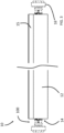
- FIG. 3 illustrates one use for the baffle assembly 100. More particularly, FIG. 3 shows a ribbon burner 10 having the baffle assembly 100.
- the ribbon burner 10 may take the form of an ERB QuadCool Ribbon Burner commercially available from Selas Heat Technology Company.
- the ribbon burner 10 includes a burner body 12, e.g., which defines a cavity for receiving fluid flow (e.g., gas/air mixture or other gaseous fuel) at one or more inlets 14, e.g., which may be positioned at one or both opposite axial ends of the burner body 12.
- a ribbon pack 15 may be included to produce a flame substantially along its entire length (e.g., a "sheet flame") by use of the fuel mixture that is injected into the burner body 12 via the inlet(s) 14.
- the baffle assembly 100 can be secured in or along a fuel supply conduit, e.g., a pipe, between the gas/air mixture source and the inlet 14 and/or the inside of the burner body 12.
- a fuel supply conduit e.g., a pipe
- a bushing 16 of a fuel supply line is illustrated in FIG. 3 , into which the baffle assembly 100 can be inserted.
- the bushing 16 may include threading (e.g., female threading) corresponding to the threads 105 and/or be otherwise arranged to receive the collar 102 of the baffle assembly 100 therein.
- the flow cavities on opposite sides of the inlet 14 may be dissimilar such that the fluid flow is subjected to entrance and/or transitional effects as it transitions through the inlet 14.
- the inlet 14 may be or include a relatively restricted flow area with respect to the flow area through the supply line, e.g., the bushing 16. In this way, absent the baffle assembly 100, the velocity of the fluid would tend to increase and the pressure decrease as the fluid enters the burner body 12.
- the flame produced by the ribbon burner 10 proximate to the inlet 14 may be less developed than the flame produced by the burner 10 at locations distal to the inlet, e.g., toward the center of the burner 10.
- positioning the baffle assembly 100 at, near, or in the inlet 14 can reduce the entrance length of the entrance and/or transitional effects, decrease the velocity, and/or increase the pressure of the fluid as it enters the burner body, thereby producing a more even and uniform flame from the burner 10 across its entire length.
- the ribbon burner 10 is just one example and that the baffle assembly 100 can be used in other embodiments.
Landscapes
- Engineering & Computer Science (AREA)
- Mechanical Engineering (AREA)
- General Engineering & Computer Science (AREA)
- Chemical & Material Sciences (AREA)
- Combustion & Propulsion (AREA)
- Physics & Mathematics (AREA)
- Fluid Mechanics (AREA)
- Gas Burners (AREA)
- Turbine Rotor Nozzle Sealing (AREA)
- Pipe Accessories (AREA)
Description
- This application claims the benefit of
U.S. Provisional Patent Application Serial No. 62/521,861, filed on June 19, 2017 - The present disclosure relates generally to a baffle assembly, and more specifically, to a baffle assembly to modify the effects on fluid flow while transitioning between different cavities, which can be utilized in a variety of industries including gas burners.
- A variety of tools, systems, and assemblies require the supply of fluid or gaseous mixtures. For example, gas burners are utilized to generate a flame to heat a product using a gaseous fuel such as acetylene, natural gas, and/or propane, among other fuel sources, e.g., air-gas mixtures may be utilized as fuel for gas powered burners. In gas burners and other applications, the fluid may transition between different cavities, e.g., between conduits or pipes of different sizes, between a storage tank or area and a conduit or pipe, through a restriction or inlet, etc. Per fluid dynamic principles, it is generally known that transitioning between different cavities, e.g., differently sized cavities, can affect the pressure, velocity, and other characteristics of the fluid flow, which are herein referred to as entrance effects or transitional effects. Additionally, the flow may experience entrance effects along an "entrance length" proximate to the transition, with the flow stabilizing at some distance distal from the transition. Referring back to gas burners (particularly ribbon burners that are arranged to produce a flame along a length of the burner), the entrance effects introduced by the transition from the fuel inlet into the burner cavity can create an issue in which the properties of the produced flame proximate to the fuel inlet differ from the properties of the flame at distances further away from the fuel inlet.
- Accordingly, there is a need in the art for an assembly for modifying the entrance and/or transitional effects of fluid flows in a reduced distance, such as for improving the operation of gas burners and other systems.
-
WO 2010/073282 A1 discloses a modulating gas burner which is designed for operation with premixing of a combustible air and gas mixture. The disclosure falls in particular within the specific technical field of modulating gas burners in which the burner power can be modulated within a predetermined modulation range in dependence on specific operating requirements.WO 2010/073282 A1 also discloses a flow guide device which is produced integrally with a shutter element in the region of an aperture. The flow guide device comprises a plurality of radial deflector fins which are integral with the shutter and spaced apart angularly at regular intervals with a spoke-like arrangement. The fins may be inclined to the axial direction of the flow through the head so as to impart a rotational component to the flow. - The present invention is directed to a baffle assembly for modifying the entrance and/or transitional effects of fluid flows, such as for improving the operation of gas burners and other systems.
- An advantage of an embodiment of the baffle assembly described herein is that it is compact in length and is easily replaceable. Another advantage is that it is easily assembled. A further advantage is that it improves flame uniformity when used with a burner, such as a ribbon burner.
- The invention provides a baffle assembly as defined in claim 1.
- In one embodiment, the legs are secured to the inner circumferential surface of the collar, the impingement plates are not secured to the inner circumferential surface of the collar, to thereby provide a free end of the impingement plate.
- In one embodiment, the second angle is defined as the first angle subtracted from a third angle measured between the leg and the impingement plate. In one embodiment, the first angle is between 5° and 30°. In one embodiment, the second angle is between 60° and 120°. In one embodiment, the impingement plates have a width and a length sufficient to block at least 80% of a flow area through the collar.
- In one embodiment, a length of the leg is approximately equal to a diameter of the collar. In one embodiment, a first length of each impingement plate is equal to between about 25% to 50% of a second length of the leg. In one embodiment, the baffle assembly includes four of the vanes equally spaced about the inner surface of the collar. In one embodiment, the collar has a circular cross-sectional shape.
- The invention also provides a burner assembly including an inlet and the baffle assembly of claim 1 installed in, at, or proximate to the inlet. In one embodiment, the burner assembly is a ribbon burner. In one embodiment, the inlet includes a first inlet and a second inlet positioned at opposite sides of a burner body.
- These and other aspects of the invention will be apparent from the embodiments described below.
- The foregoing will be apparent from the following more particular description of example embodiments of the present invention, as illustrated in the accompanying drawings in which like reference characters refer to the same parts throughout the different views. The drawings are not necessarily to scale, emphasis instead being placed upon illustrating embodiments of the present disclosure.
-
FIG. 1 is a perspective view of a baffle assembly, in accordance with an example embodiment of the present invention. -
FIG. 2A is a front view of the assembly of the baffle assembly ofFIG. 1 , in accordance with an example embodiment of the present invention. -
FIG. 2B is a side view of the assembly of the baffle assembly ofFIG. 1 , in accordance with an example embodiment of the present invention. -
FIG. 3 is a schematic side view of the baffle assembly ofFIG. 1 installed on each end of a ribbon burner, in accordance with an example embodiment of the present invention. - A description of example embodiments of the invention follows.
- A perspective view of a baffle assembly is shown in
FIG. 1 , in accordance with an embodiment.FIGS. 2A and 2B are respective front and side views of the assembly of the baffle assembly ofFIG. 1 . The following should be viewed based onFIGS. 1-2B . - The
baffle assembly 100 generally includes a hub orcollar 102 having a plurality ofvanes 104 secured thereto. As discussed in more detail below, thevanes 104 of thebaffle assembly 100 are arranged to reduce entrance effects and/or transitional effects on the fluid flow as the flow of a fluid transitions between different sized, shaped, structured, and/or oriented flow cavities. For example, thebaffle assembly 100 may be positioned at, in, or near the transition of a pipe or cavity having a relatively larger cross-sectional flow area into a pipe or cavity having a relatively smaller cross-sectional flow area. Namely, thebaffle assembly 100 can be used to create a more even cross-sectional distribution of fluid flow. Additionally, thebaffle assembly 100 can be useful to decrease the velocity of the fluid flow, thereby corresponding to a relative increase in fluid pressure, which can be advantageous in a number of applications. In accordance with the embodiments disclosed herein, those of ordinary skill in the art will recognize transitions between other fluid flow cavities that may result in undesirable entrance and/or transitional effects that can be alleviated by thebaffle assembly 100. - The
collar 102 may be or comprise a short pipe nipple, e.g., having threads 105 (shown schematically only with broken lines to indicate approximate thread dimensions) for threaded engagement in, with, or between one or more pipes, conduits, bushings, cavities, etc. In this way, as discussed herein, thebaffle assembly 100 can be positioned at or near the interface or transition between two different fluid flow cavities. For example, as shown inFIG. 2B , thethreads 105 may be in accordance with any desired specification or standard, such as the National Pipe Thread Taper (NPT) standards. - In the illustrated embodiment, the
collar 102 is shown having a substantially circular cross-sectional shape, although it is to be appreciated that other shapes can be utilized depending on the particular system in which thebaffle assembly 100 is installed. For example, if a press fit, adhesives, fasteners, or some other fastening means or mechanism is utilized instead of thethreads 105, then other shapes such as rectangular, triangular, polygonal, etc. may be used. - In the illustrated embodiment, each
vane 104 includes animpingement plate 106 and aleg 108. As illustrated, thebaffle assembly 100 includes four of thevanes 104 equally spaced about and secured at anarea 110 to aninner surface 112 of thecollar 102, although other numbers of vanes may be utilized. The connection between thevanes 104 and thecollar 102 at thearea 110 may include or be defined by welds, e.g., tack welds, or any other manner. For example, a groove just smaller than a thickness t of thelegs 108 can be cut into theinner surface 112 and thelegs 108 press fit into the grooves. Those of ordinary skill in the art will appreciate other means of securement, e.g., adhesives, clips, fasteners, etc. - The
legs 108 extend from thecollar 102 at an angle α with respect to a central axis A, while theimpingement plate 106 is bent at an angle β with respect to theleg 108. Accordingly, it is to be appreciated that theimpingement plates 106 are arranged with respect to the central axis A at an angle equal to (β - α). By use of multiple circumferentially spacedvanes 104, each having one of thelegs 108 at the angle α, thelegs 108 can induce or promote a spiraling, rotation, or spinning of the fluid flow as it passes through thebaffle assembly 100. That is, fluid flow reaching the baffle assembly 100 (e.g., generally flowing parallel to the axis A through a pipe or other cavity) will first pass through thecollar 102 and then encounter thelegs 108. Due to the angled orientation of thelegs 108, the fluid flow is urged out of alignment with the central axis A. That is, each respective portion of the fluid flowing through thebaffle assembly 100 is directed at the angle α away from the central axis A. - It is noted that each of the
legs 108 is arranged to urge the fluid flow in a different direction relative to the central axis A (although each direction is at least partially radially outwardly directed). This promotes the aforementioned spiraling or rotation of the fluid flow. In one embodiment, the angle α is between about 5° and 30° or more particularly between about 10° and 20°. Advantageously, these ranges of angles promote rotational or spiraling in the flow while remaining substantially axially aligned with central axis A. - As the fluid flow continues, it next encounters the
impingement plates 106, which are substantially perpendicular and/or transverse to the central axis A. For example, the angle β may be approximately equal to 90°, and/or the value of β - α (i.e., the angle of theimpingement plates 106 with respect to the central axis A) may be approximately equal to 90°, e.g., between about 120° and 60°. In this way, fluid flow encountering theimpingement plates 106 is much more sharply urged in a substantially radial direction (i.e., perpendicular to the central axis A). Additionally, since theimpingement plates 106 are substantially perpendicular and/or transverse to the central axis A, the velocity of the flow encountering theimpingement plates 106 is significantly reduced, as the flow is redirected from the axial direction to the radial direction. - Advantageously in many applications, a reduction in velocity is accompanied by an increase in pressure and a shorter entrance length (along which entrance length the flow is subjected to entrance or transitional effects before stabilizing). Together with the spiraling or rotation imparted by the
legs 108 discussed above, uniformity in the distribution of the flow (e.g., mixing of the flow) is maintained while the velocity is decreased, the pressure is increased, and/or the entrance length is decreased. - The
vanes 104 can be made of any suitable material, for example, mild steel or resilient plastic. The dimensions of thevanes 104 may be set to facilitate the above-described or other functionalities. For example, thelegs 108 may have a length L1 that is suitable for imparting a sufficient amount of spiraling to the flow of fluid. The length L1 may be influenced by the size of thecollar 102, the change in dimensions or structure of the flow cavities on opposite sides of thebaffle assembly 100, the viscosity, velocity, pressure, or other properties of the flow of fluid, etc. In one embodiment, the length L1 of thelegs 108 is approximately equal to the diameter of thecollar 102, e.g., 50,8mm (2") in one embodiment. - The
impingement plates 106 likewise have a length L2, which can be set to facilitate the redirection of the flow from a substantially axial direction (i.e., parallel to the axis A) to a substantially perpendicular direction (i.e., perpendicular to the axis A). In one embodiment, the length L2 is approximately 25-50% of the length L1 and/or of the diameter of thecollar 102. For example, in one embodiment, the length L2 may be 19,05mm (3/4 inch) and the length L1 and/or the diameter of thecollar 102 may be 50,8mm (2"). - Additionally, the
impingement plates 106 may have a width W to assist in the aforementioned functionality. The width W can be set so that it assists in suitably blocking or impeding the flow of fluid to a desired level. For example, smaller values of the width W could be used to impede the flow of fluid to a lesser degree, thereby decreasing the velocity and/or increasing the pressure to a lesser degree than if a larger value were used for the width W. In one embodiment, the length L2 and the width W are set to block at least the majority of the flow area through thecollar 102. For example, as shown inFIG. 2A , theimpingement plates 106 block substantially all of the flow area through thecollar 102 with the exception of a small portion near the central axis A and the small portions between each adjacent set of theimpingement plates 106. In one embodiment, theimpingement plates 106 are dimensioned to block at least about 75% of the flow area of thecollar 102. -
FIG. 3 illustrates one use for thebaffle assembly 100. More particularly,FIG. 3 shows aribbon burner 10 having thebaffle assembly 100. Theribbon burner 10 may take the form of an ERB QuadCool Ribbon Burner commercially available from Selas Heat Technology Company. Theribbon burner 10 includes aburner body 12, e.g., which defines a cavity for receiving fluid flow (e.g., gas/air mixture or other gaseous fuel) at one ormore inlets 14, e.g., which may be positioned at one or both opposite axial ends of theburner body 12. Aribbon pack 15 may be included to produce a flame substantially along its entire length (e.g., a "sheet flame") by use of the fuel mixture that is injected into theburner body 12 via the inlet(s) 14. - The
baffle assembly 100 can be secured in or along a fuel supply conduit, e.g., a pipe, between the gas/air mixture source and theinlet 14 and/or the inside of theburner body 12. For example, abushing 16 of a fuel supply line is illustrated inFIG. 3 , into which thebaffle assembly 100 can be inserted. For example, thebushing 16 may include threading (e.g., female threading) corresponding to thethreads 105 and/or be otherwise arranged to receive thecollar 102 of thebaffle assembly 100 therein. - As discussed above, the flow cavities on opposite sides of the inlet 14 (e.g., the inside of the
burner body 12 with respect to the fuel supply line) may be dissimilar such that the fluid flow is subjected to entrance and/or transitional effects as it transitions through theinlet 14. For example, theinlet 14 may be or include a relatively restricted flow area with respect to the flow area through the supply line, e.g., thebushing 16. In this way, absent thebaffle assembly 100, the velocity of the fluid would tend to increase and the pressure decrease as the fluid enters theburner body 12. As a result of the decreased pressure and/or other entrance effects, the flame produced by theribbon burner 10 proximate to theinlet 14 may be less developed than the flame produced by theburner 10 at locations distal to the inlet, e.g., toward the center of theburner 10. Advantageously, as discussed above, positioning thebaffle assembly 100 at, near, or in theinlet 14 can reduce the entrance length of the entrance and/or transitional effects, decrease the velocity, and/or increase the pressure of the fluid as it enters the burner body, thereby producing a more even and uniform flame from theburner 10 across its entire length. Those of ordinary skill in the art will recognize that theribbon burner 10 is just one example and that thebaffle assembly 100 can be used in other embodiments. - While several inventive embodiments have been described and illustrated herein, those of ordinary skill in the art will readily envision a variety of other means and/or structures for performing the function and/or obtaining the results and/or one or more of the advantages described herein. More generally, those skilled in the art will readily appreciate that all parameters, dimensions, materials, and configurations described herein are meant to be exemplary and that the actual parameters, dimensions, materials, and/or configurations will depend upon the specific application or applications for which the inventive teachings is/are used. Those skilled in the art will recognize, or be able to ascertain using no more than routine experimentation, many equivalents to the specific inventive embodiments described herein. It is, therefore, to be understood that the foregoing embodiments are presented by way of example only and that, within the scope of the appended claims, inventive embodiments may be practiced otherwise than as specifically described and claimed.
Claims (13)
- A baffle assembly (100), comprising:a collar (102) having a central axis and an inner circumferential surface (112); and,a plurality of vanes (104) secured to the inner circumferential surface of the collar, each vane comprising:a leg (108) extending from the collar at a first angle with respect to the central axis, the first angle of the leg configured to impart rotation to a flow of fluid through the baffle assembly; andan impingement plate (106) extending from the leg at a second angle with respect to the central axis, wherein the second angle is greater than the first angle;wherein the baffle assembly (100) is configured such that the flow of fluid through the baffle assembly (100) first passes through the collar (102) and encounters the leg (108) of each of the plurality of vanes (104) and thereafter encounters the impingement plate (106) of the respective vanes (104), such that fluid flow encountering each of the impingement plates (106) is urged in a substantially radial direction.
- The baffle assembly (100) of claim 1, wherein:the legs (108) are secured to the inner circumferential surface (112) of the collar (102); andthe impingement plates (106) are not secured to the inner circumferential surface (112) of the collar (102), to thereby provide a free end of the impingement plate (106).
- The baffle assembly (100) of claim 1, wherein the second angle is defined as the first angle subtracted from a third angle measured between the leg (108) and the impingement plate (106).
- The baffle assembly (100) of claim 1, wherein the first angle is between 5° and 30°.
- The baffle assembly (100) of claim 1, wherein the second angle is between 60° and 120°.
- The baffle assembly (100) of claim 1, wherein the impingement plates (106) have a width and a length sufficient to block at least 80% of a flow area through the collar (102).
- The baffle assembly (100) of claim 1, wherein a length of the leg (108) is approximately equal to a diameter of the collar (102).
- The baffle assembly (100) of claim 1, wherein a length of each impingement plate (106) is equal to between about 25% to 50% of a length of the leg.
- The baffle assembly of claim 1, comprising four of the vanes (104) equally spaced about the inner surface (112) of the collar (102).
- The baffle assembly (100) of claim 1, wherein the collar (102) has a circular cross-sectional shape.
- A burner assembly having an inlet (14) and the baffle assembly (100) of claim 1 installed in, at, or proximate to the inlet.
- The burner assembly of claim 11, wherein the burner assembly is a ribbon burner.
- The burner assembly of claim 12, wherein the inlet (14) includes a first inlet and a second inlet positioned at opposite sides of a burner body.
Applications Claiming Priority (2)
| Application Number | Priority Date | Filing Date | Title |
|---|---|---|---|
| US201762521861P | 2017-06-19 | 2017-06-19 | |
| PCT/US2018/038285 WO2018236868A1 (en) | 2017-06-19 | 2018-06-19 | Baffle assembly for modifying transitional flow effects between different cavities |
Publications (4)
| Publication Number | Publication Date |
|---|---|
| EP3642537A1 EP3642537A1 (en) | 2020-04-29 |
| EP3642537A4 EP3642537A4 (en) | 2021-03-10 |
| EP3642537C0 EP3642537C0 (en) | 2024-11-13 |
| EP3642537B1 true EP3642537B1 (en) | 2024-11-13 |
Family
ID=64656176
Family Applications (1)
| Application Number | Title | Priority Date | Filing Date |
|---|---|---|---|
| EP18819871.7A Active EP3642537B1 (en) | 2017-06-19 | 2018-06-19 | Baffle assembly for modifying transitional flow effects between different cavities |
Country Status (10)
| Country | Link |
|---|---|
| US (2) | US10746207B2 (en) |
| EP (1) | EP3642537B1 (en) |
| JP (2) | JP6834059B2 (en) |
| KR (3) | KR20200013732A (en) |
| CN (2) | CN111033123B (en) |
| CA (1) | CA3066935C (en) |
| ES (1) | ES3008462T3 (en) |
| MX (1) | MX2019014634A (en) |
| PL (1) | PL3642537T3 (en) |
| WO (1) | WO2018236868A1 (en) |
Families Citing this family (4)
| Publication number | Priority date | Publication date | Assignee | Title |
|---|---|---|---|---|
| US10746207B2 (en) * | 2017-06-19 | 2020-08-18 | Selas Heat Technology Company Llc | Baffle assembly for modifying transitional flow effects between different cavities |
| GB2595727A (en) * | 2020-06-05 | 2021-12-08 | Edwards Ltd | Inlet assembly |
| USD1066275S1 (en) * | 2022-04-04 | 2025-03-11 | Applied Materials, Inc. | Baffle for anti-rotation process kit for substrate processing chamber |
| USD1076837S1 (en) * | 2023-01-19 | 2025-05-27 | Lam Research Corporation | Baffle |
Citations (1)
| Publication number | Priority date | Publication date | Assignee | Title |
|---|---|---|---|---|
| EP2368069B1 (en) * | 2008-12-23 | 2017-07-26 | Sit S.P.A. | A premix gas burner |
Family Cites Families (28)
| Publication number | Priority date | Publication date | Assignee | Title |
|---|---|---|---|---|
| US1778790A (en) * | 1927-08-30 | 1930-10-21 | Julius Haber | Gaseous-fuel-mixing device |
| US1868902A (en) * | 1928-07-13 | 1932-07-26 | Thomas E Jackson | Auxiliary air intake and mixing device |
| US3544290A (en) * | 1965-10-21 | 1970-12-01 | Raymond C Larson Sr | Fuel atomizing unit |
| JPS49119233A (en) | 1973-03-19 | 1974-11-14 | ||
| JPS554653Y2 (en) * | 1974-11-28 | 1980-02-04 | ||
| JPS5169140A (en) | 1974-12-04 | 1976-06-15 | Yuasa Battery Co Ltd | MITSUPEIGATADENCHI |
| JPS5729126Y2 (en) * | 1976-07-05 | 1982-06-25 | ||
| JPS5369290A (en) | 1976-12-03 | 1978-06-20 | Mitsui Toatsu Chem Inc | Curable resin composition |
| US4255124A (en) * | 1978-10-05 | 1981-03-10 | Baranowski Jr Frank | Static fluid-swirl mixing |
| US4464108A (en) * | 1980-11-21 | 1984-08-07 | Donald Korenyi | Combustion apparatus |
| US4431403A (en) * | 1981-04-23 | 1984-02-14 | Hauck Manufacturing Company | Burner and method |
| US4884555A (en) | 1988-11-21 | 1989-12-05 | A. O. Smith Corporation | Swirl combuster burner |
| JPH06101815A (en) * | 1992-09-18 | 1994-04-12 | Hitachi Ltd | Burners and combustors for premixed combustion |
| US5408984A (en) | 1993-07-26 | 1995-04-25 | General Electric Company | Two stage flame stabilization for a gas burner |
| JPH08247421A (en) | 1995-03-13 | 1996-09-27 | Nkk Corp | Radiant tube burner |
| DE19708218C2 (en) * | 1997-02-28 | 2002-01-31 | Rational Ag | gas burner |
| US6042263A (en) * | 1998-04-29 | 2000-03-28 | Mentzer; Marvin R. | Mixed phase ruff body flow diffuser |
| US6200131B1 (en) * | 2000-02-29 | 2001-03-13 | Recot, Inc. | Quick-connect burner set for ovens |
| US20080078183A1 (en) * | 2006-10-03 | 2008-04-03 | General Electric Company | Liquid fuel enhancement for natural gas swirl stabilized nozzle and method |
| US7635264B2 (en) * | 2007-12-20 | 2009-12-22 | 3M Innovative Properties Company | Attenuating combustion noise of premixed flames |
| US8978705B2 (en) * | 2009-06-04 | 2015-03-17 | National Oilwell Varco, L.P. | Apparatus for reducing turbulence in a fluid stream |
| US8347733B2 (en) * | 2010-10-25 | 2013-01-08 | Cameron International Corporation | Conditioner, apparatus and method |
| KR102005545B1 (en) * | 2013-08-12 | 2019-07-30 | 한화에어로스페이스 주식회사 | Swirler |
| US9726368B2 (en) * | 2013-12-16 | 2017-08-08 | Pro-Iroda Industries, Inc. | Adjustable vortex flame device |
| CN203656984U (en) * | 2014-01-15 | 2014-06-18 | 大连海事大学 | A Variable Swirl Number Cyclone |
| KR101895137B1 (en) * | 2014-03-11 | 2018-09-04 | 미츠비시 히타치 파워 시스템즈 가부시키가이샤 | Combustion burner for boiler |
| DE102014116411B4 (en) * | 2014-11-11 | 2024-05-29 | Choren Industrietechnik GmbH | Swirl body and burner with swirl body and method for producing the swirl body |
| US10746207B2 (en) * | 2017-06-19 | 2020-08-18 | Selas Heat Technology Company Llc | Baffle assembly for modifying transitional flow effects between different cavities |
-
2018
- 2018-06-19 US US16/012,218 patent/US10746207B2/en active Active
- 2018-06-19 EP EP18819871.7A patent/EP3642537B1/en active Active
- 2018-06-19 KR KR1020197038969A patent/KR20200013732A/en not_active Ceased
- 2018-06-19 WO PCT/US2018/038285 patent/WO2018236868A1/en not_active Ceased
- 2018-06-19 CN CN201880041336.9A patent/CN111033123B/en active Active
- 2018-06-19 CA CA3066935A patent/CA3066935C/en active Active
- 2018-06-19 PL PL18819871.7T patent/PL3642537T3/en unknown
- 2018-06-19 CN CN202210942523.2A patent/CN115479275B/en active Active
- 2018-06-19 ES ES18819871T patent/ES3008462T3/en active Active
- 2018-06-19 KR KR1020237044703A patent/KR102758195B1/en active Active
- 2018-06-19 MX MX2019014634A patent/MX2019014634A/en unknown
- 2018-06-19 KR KR1020237000731A patent/KR20230011488A/en not_active Ceased
- 2018-06-19 JP JP2020519024A patent/JP6834059B2/en active Active
-
2020
- 2020-07-15 US US16/929,207 patent/US11530711B2/en active Active
-
2021
- 2021-02-03 JP JP2021015754A patent/JP2021067455A/en active Pending
Patent Citations (1)
| Publication number | Priority date | Publication date | Assignee | Title |
|---|---|---|---|---|
| EP2368069B1 (en) * | 2008-12-23 | 2017-07-26 | Sit S.P.A. | A premix gas burner |
Also Published As
| Publication number | Publication date |
|---|---|
| ES3008462T3 (en) | 2025-03-24 |
| KR20240006082A (en) | 2024-01-12 |
| WO2018236868A1 (en) | 2018-12-27 |
| KR20230011488A (en) | 2023-01-20 |
| US20180363686A1 (en) | 2018-12-20 |
| JP2020524257A (en) | 2020-08-13 |
| US20200340506A1 (en) | 2020-10-29 |
| JP6834059B2 (en) | 2021-02-24 |
| CN115479275A (en) | 2022-12-16 |
| MX2019014634A (en) | 2020-02-07 |
| US10746207B2 (en) | 2020-08-18 |
| PL3642537T3 (en) | 2025-03-24 |
| KR20200013732A (en) | 2020-02-07 |
| EP3642537A4 (en) | 2021-03-10 |
| CA3066935A1 (en) | 2018-12-27 |
| CN111033123A (en) | 2020-04-17 |
| EP3642537C0 (en) | 2024-11-13 |
| CN115479275B (en) | 2026-02-17 |
| KR102758195B1 (en) | 2025-01-22 |
| EP3642537A1 (en) | 2020-04-29 |
| JP2021067455A (en) | 2021-04-30 |
| BR112019026849A2 (en) | 2020-06-30 |
| CA3066935C (en) | 2023-07-04 |
| CN111033123B (en) | 2022-08-23 |
| US11530711B2 (en) | 2022-12-20 |
Similar Documents
| Publication | Publication Date | Title |
|---|---|---|
| US11530711B2 (en) | Baffle assembly for modifying transitional flow effects between different cavities | |
| US9371992B2 (en) | Low NOx burner with low pressure drop | |
| CN103429959B (en) | High perimeter stability burner | |
| US8939759B2 (en) | Tubular burner | |
| JP2013253769A (en) | Combustor assembly having fuel pre-mixer | |
| JP2014048040A (en) | Premix burner | |
| KR20160064155A (en) | Combustion burner for boiler | |
| RU2605166C2 (en) | Universal mixing head swirl atomizer for gas burner | |
| JP2009531641A (en) | Burner equipment | |
| JP5872703B2 (en) | Improved vortex combustion mixture torch | |
| EP2242952B1 (en) | A premix gas burner | |
| EP3315861B1 (en) | Gas burner | |
| US9915426B2 (en) | Impinging-type temperature uniformity device | |
| BR122024019943A2 (en) | BURNER ASSEMBLY | |
| BR112019026849B1 (en) | DEFLECTOR ASSEMBLY AND BURNER ASSEMBLY | |
| RU2860055C2 (en) | Deflagration- and detonation-proof surface combustion gas burner | |
| CN107906514B (en) | Flat flame low-nitrogen burner | |
| AU2011239300B2 (en) | Tubular burner | |
| CN105351931A (en) | Equal-diameter constant pressure pipe and injection type combustion device | |
| GB2510173A (en) | Reduced noise burner |
Legal Events
| Date | Code | Title | Description |
|---|---|---|---|
| STAA | Information on the status of an ep patent application or granted ep patent |
Free format text: STATUS: THE INTERNATIONAL PUBLICATION HAS BEEN MADE |
|
| PUAI | Public reference made under article 153(3) epc to a published international application that has entered the european phase |
Free format text: ORIGINAL CODE: 0009012 |
|
| STAA | Information on the status of an ep patent application or granted ep patent |
Free format text: STATUS: REQUEST FOR EXAMINATION WAS MADE |
|
| 17P | Request for examination filed |
Effective date: 20191218 |
|
| AK | Designated contracting states |
Kind code of ref document: A1 Designated state(s): AL AT BE BG CH CY CZ DE DK EE ES FI FR GB GR HR HU IE IS IT LI LT LU LV MC MK MT NL NO PL PT RO RS SE SI SK SM TR |
|
| AX | Request for extension of the european patent |
Extension state: BA ME |
|
| DAV | Request for validation of the european patent (deleted) | ||
| DAX | Request for extension of the european patent (deleted) | ||
| A4 | Supplementary search report drawn up and despatched |
Effective date: 20210210 |
|
| RIC1 | Information provided on ipc code assigned before grant |
Ipc: F23D 14/70 20060101AFI20210204BHEP Ipc: F23D 14/62 20060101ALI20210204BHEP Ipc: F23D 14/58 20060101ALI20210204BHEP |
|
| STAA | Information on the status of an ep patent application or granted ep patent |
Free format text: STATUS: EXAMINATION IS IN PROGRESS |
|
| 17Q | First examination report despatched |
Effective date: 20220816 |
|
| P01 | Opt-out of the competence of the unified patent court (upc) registered |
Effective date: 20230530 |
|
| GRAP | Despatch of communication of intention to grant a patent |
Free format text: ORIGINAL CODE: EPIDOSNIGR1 |
|
| STAA | Information on the status of an ep patent application or granted ep patent |
Free format text: STATUS: GRANT OF PATENT IS INTENDED |
|
| GRAJ | Information related to disapproval of communication of intention to grant by the applicant or resumption of examination proceedings by the epo deleted |
Free format text: ORIGINAL CODE: EPIDOSDIGR1 |
|
| STAA | Information on the status of an ep patent application or granted ep patent |
Free format text: STATUS: EXAMINATION IS IN PROGRESS |
|
| INTG | Intention to grant announced |
Effective date: 20240422 |
|
| GRAP | Despatch of communication of intention to grant a patent |
Free format text: ORIGINAL CODE: EPIDOSNIGR1 |
|
| STAA | Information on the status of an ep patent application or granted ep patent |
Free format text: STATUS: GRANT OF PATENT IS INTENDED |
|
| INTC | Intention to grant announced (deleted) | ||
| INTG | Intention to grant announced |
Effective date: 20240613 |
|
| GRAS | Grant fee paid |
Free format text: ORIGINAL CODE: EPIDOSNIGR3 |
|
| GRAA | (expected) grant |
Free format text: ORIGINAL CODE: 0009210 |
|
| STAA | Information on the status of an ep patent application or granted ep patent |
Free format text: STATUS: THE PATENT HAS BEEN GRANTED |
|
| AK | Designated contracting states |
Kind code of ref document: B1 Designated state(s): AL AT BE BG CH CY CZ DE DK EE ES FI FR GB GR HR HU IE IS IT LI LT LU LV MC MK MT NL NO PL PT RO RS SE SI SK SM TR |
|
| REG | Reference to a national code |
Ref country code: GB Ref legal event code: FG4D |
|
| REG | Reference to a national code |
Ref country code: CH Ref legal event code: EP |
|
| REG | Reference to a national code |
Ref country code: DE Ref legal event code: R096 Ref document number: 602018076580 Country of ref document: DE |
|
| REG | Reference to a national code |
Ref country code: IE Ref legal event code: FG4D |
|
| U01 | Request for unitary effect filed |
Effective date: 20241209 |
|
| P04 | Withdrawal of opt-out of the competence of the unified patent court (upc) registered |
Free format text: CASE NUMBER: APP_66591/2024 Effective date: 20241216 |
|
| U07 | Unitary effect registered |
Designated state(s): AT BE BG DE DK EE FI FR IT LT LU LV MT NL PT RO SE SI Effective date: 20241219 |
|
| REG | Reference to a national code |
Ref country code: ES Ref legal event code: FG2A Ref document number: 3008462 Country of ref document: ES Kind code of ref document: T3 Effective date: 20250324 |
|
| REG | Reference to a national code |
Ref country code: SK Ref legal event code: T3 Ref document number: E 45901 Country of ref document: SK |
|
| PG25 | Lapsed in a contracting state [announced via postgrant information from national office to epo] |
Ref country code: IS Free format text: LAPSE BECAUSE OF FAILURE TO SUBMIT A TRANSLATION OF THE DESCRIPTION OR TO PAY THE FEE WITHIN THE PRESCRIBED TIME-LIMIT Effective date: 20250313 Ref country code: HR Free format text: LAPSE BECAUSE OF FAILURE TO SUBMIT A TRANSLATION OF THE DESCRIPTION OR TO PAY THE FEE WITHIN THE PRESCRIBED TIME-LIMIT Effective date: 20241113 |
|
| PG25 | Lapsed in a contracting state [announced via postgrant information from national office to epo] |
Ref country code: NO Free format text: LAPSE BECAUSE OF FAILURE TO SUBMIT A TRANSLATION OF THE DESCRIPTION OR TO PAY THE FEE WITHIN THE PRESCRIBED TIME-LIMIT Effective date: 20250213 |
|
| PG25 | Lapsed in a contracting state [announced via postgrant information from national office to epo] |
Ref country code: GR Free format text: LAPSE BECAUSE OF FAILURE TO SUBMIT A TRANSLATION OF THE DESCRIPTION OR TO PAY THE FEE WITHIN THE PRESCRIBED TIME-LIMIT Effective date: 20250214 |
|
| PG25 | Lapsed in a contracting state [announced via postgrant information from national office to epo] |
Ref country code: RS Free format text: LAPSE BECAUSE OF FAILURE TO SUBMIT A TRANSLATION OF THE DESCRIPTION OR TO PAY THE FEE WITHIN THE PRESCRIBED TIME-LIMIT Effective date: 20250213 |
|
| PG25 | Lapsed in a contracting state [announced via postgrant information from national office to epo] |
Ref country code: SM Free format text: LAPSE BECAUSE OF FAILURE TO SUBMIT A TRANSLATION OF THE DESCRIPTION OR TO PAY THE FEE WITHIN THE PRESCRIBED TIME-LIMIT Effective date: 20241113 |
|
| PGFP | Annual fee paid to national office [announced via postgrant information from national office to epo] |
Ref country code: PL Payment date: 20250529 Year of fee payment: 8 |
|
| PGFP | Annual fee paid to national office [announced via postgrant information from national office to epo] |
Ref country code: GB Payment date: 20250529 Year of fee payment: 8 |
|
| U20 | Renewal fee for the european patent with unitary effect paid |
Year of fee payment: 8 Effective date: 20250606 |
|
| PGFP | Annual fee paid to national office [announced via postgrant information from national office to epo] |
Ref country code: SK Payment date: 20250523 Year of fee payment: 8 |
|
| PGFP | Annual fee paid to national office [announced via postgrant information from national office to epo] |
Ref country code: CZ Payment date: 20250530 Year of fee payment: 8 |
|
| PLBE | No opposition filed within time limit |
Free format text: ORIGINAL CODE: 0009261 |
|
| STAA | Information on the status of an ep patent application or granted ep patent |
Free format text: STATUS: NO OPPOSITION FILED WITHIN TIME LIMIT |
|
| PGFP | Annual fee paid to national office [announced via postgrant information from national office to epo] |
Ref country code: ES Payment date: 20250707 Year of fee payment: 8 |
|
| PGFP | Annual fee paid to national office [announced via postgrant information from national office to epo] |
Ref country code: CH Payment date: 20250701 Year of fee payment: 8 |
|
| 26N | No opposition filed |
Effective date: 20250814 |
|
| PG25 | Lapsed in a contracting state [announced via postgrant information from national office to epo] |
Ref country code: MC Free format text: LAPSE BECAUSE OF FAILURE TO SUBMIT A TRANSLATION OF THE DESCRIPTION OR TO PAY THE FEE WITHIN THE PRESCRIBED TIME-LIMIT Effective date: 20241113 |
|
| PG25 | Lapsed in a contracting state [announced via postgrant information from national office to epo] |
Ref country code: IE Free format text: LAPSE BECAUSE OF NON-PAYMENT OF DUE FEES Effective date: 20250619 |