EP3642395B1 - A method of recovering pt or ag or pt and ag from sulfate based metal solutions - Google Patents
A method of recovering pt or ag or pt and ag from sulfate based metal solutions Download PDFInfo
- Publication number
- EP3642395B1 EP3642395B1 EP18739573.6A EP18739573A EP3642395B1 EP 3642395 B1 EP3642395 B1 EP 3642395B1 EP 18739573 A EP18739573 A EP 18739573A EP 3642395 B1 EP3642395 B1 EP 3642395B1
- Authority
- EP
- European Patent Office
- Prior art keywords
- electrode
- potential
- replacement
- solution
- sce
- Prior art date
- Legal status (The legal status is an assumption and is not a legal conclusion. Google has not performed a legal analysis and makes no representation as to the accuracy of the status listed.)
- Active
Links
Images

Classifications
-
- C—CHEMISTRY; METALLURGY
- C25—ELECTROLYTIC OR ELECTROPHORETIC PROCESSES; APPARATUS THEREFOR
- C25C—PROCESSES FOR THE ELECTROLYTIC PRODUCTION, RECOVERY OR REFINING OF METALS; APPARATUS THEREFOR
- C25C1/00—Electrolytic production, recovery or refining of metals by electrolysis of solutions
- C25C1/20—Electrolytic production, recovery or refining of metals by electrolysis of solutions of noble metals
-
- C—CHEMISTRY; METALLURGY
- C22—METALLURGY; FERROUS OR NON-FERROUS ALLOYS; TREATMENT OF ALLOYS OR NON-FERROUS METALS
- C22B—PRODUCTION AND REFINING OF METALS; PRETREATMENT OF RAW MATERIALS
- C22B11/00—Obtaining noble metals
- C22B11/04—Obtaining noble metals by wet processes
- C22B11/042—Recovery of noble metals from waste materials
-
- C—CHEMISTRY; METALLURGY
- C25—ELECTROLYTIC OR ELECTROPHORETIC PROCESSES; APPARATUS THEREFOR
- C25C—PROCESSES FOR THE ELECTROLYTIC PRODUCTION, RECOVERY OR REFINING OF METALS; APPARATUS THEREFOR
- C25C7/00—Constructional parts, or assemblies thereof, of cells; Servicing or operating of cells
- C25C7/02—Electrodes; Connections thereof
-
- Y—GENERAL TAGGING OF NEW TECHNOLOGICAL DEVELOPMENTS; GENERAL TAGGING OF CROSS-SECTIONAL TECHNOLOGIES SPANNING OVER SEVERAL SECTIONS OF THE IPC; TECHNICAL SUBJECTS COVERED BY FORMER USPC CROSS-REFERENCE ART COLLECTIONS [XRACs] AND DIGESTS
- Y02—TECHNOLOGIES OR APPLICATIONS FOR MITIGATION OR ADAPTATION AGAINST CLIMATE CHANGE
- Y02P—CLIMATE CHANGE MITIGATION TECHNOLOGIES IN THE PRODUCTION OR PROCESSING OF GOODS
- Y02P10/00—Technologies related to metal processing
- Y02P10/20—Recycling
Definitions
- Primary and secondary raw materials in base metal production such as in Zn, Ni and Cu production are commonly processed hydrometallurgically in some stage of the process.
- the most common media used in processing is sulfate-based solution.
- Both primary and secondary raw materials contain not only base metals but also some amount of Pt and/or Ag and other elements, depending on the source. As a result, some part of these elements end up to the process solutions, even though majority of the Pt and/or Ag can be systematically removed as by-products. However, at some point of the process, the solutions or side products still contain Pt and/or Ag, but at such low concentrations, that removal of these is not considered as economically attractive.
- the process parameters need to be carefully adjusted in order to get the base metal deposited with good quality and energy efficiency.
- the methods used for the adjusting of the process window and minimizing hydrogen evolution are for example additives, adjusting pH, adjusting solution concentration and temperature.
- the electrode material affects the starting potential of the hydrogen evolution.
- Pt and Ag are more noble than base metals in sulfate based solutions and a majority of the Pt and/or Ag end up to the anode slime or to the Pt and/or Ag rich side-product or residue.
- minor amount of Pt and/or Ag can be present in the sulfate solution during the process.
- this minor amount of Pt and/or Ag in the process solutions are wasted e.g. to the cathode during electrowinning or electrorefining of base metals, to the solution purification solutions, to the liberator cells, to the liberator cell cathodes, solids or residues or other side streams and/or products.
- nickel has also been commonly used as a sacrificial metal for the formation of Pt or PtNi films or nanoparticles, utilising redox replacement reaction between Ni and Pt, often in combination of electrodeposition (e.g. Rettew (ECST and JES at 2009), Maijenburg et al. (2012), S. Papadimitriou et al. (2010, 2008), Tegou et al. (2009, 2010), Zhang et al (2012)).
- electrodeposition and redox replacement steps are performed in separate electrolytes (electrodeposition in a nickel containing electrolyte and redox replacement in Pt containing electrolyte).
- Pt and/or Ag are enriched on the surface of an electrode
- the enrichment can be defined as a ratio of a weight-% of the recovered metal on the electrode surface compared to weight-% of it originally in the solution (wt-% of replacement metal on the surface / wt-% of replacement metal originally in the solution). According to a preferred embodiment the enrichment is at least 1 000 fold, more preferably at least 10 000 fold and even more preferably at least 500 000 fold.
- An object of the present invention is to provide a method of recovering of Pt and/or Ag from a sulfate based solution containing Zn and/or Ni, such as process solutions from hydrometallurgical plant.
- the solution originates form leaching plant for ores or concentrates, Zn electrowinning plant, nickel sulfuric acid leaching plant, electrowinning or electrorefining process, solution purification process, slime treatment process or side-stream treatment process.
- the sulfate process solution can also originate from leaching of secondary raw materials.
- cycling between the electrodeposition step 1 and the redox replacement step 2 takes place.
- the number of cycles between the ED and RR steps can be varied.
- multistep pattern can be used instead of simple cycling. After the appropriate number of repetitions of step 1 and step 2, the product rich in Pt and/or Ag is achieved.
- high surface area 3D carbon is used as the electrode on which the metals are deposited or enriched.
- Example 1 shows that Ag present at very low quantity (1 ppb, 50 ppb, 500 ppb, 1 ppm) can be recovered from Zn containing solution on Pt electrode using this method. This is a novel feature, since such low values are not typically recovered from hydrometallurgical process solutions. This finding is even more remarkable considering that the typical base metal concentration is high (in the present case Zn), typically >20 g/L.
- the replacement metal content (Pt or Ag) can be below detection limit of typical analysis methods such as AAS, ICP-OES.
- the method comprises of two steps: (step 1) electrodeposition of sacrificial metal such as Zn and/or Ni by applying an external potential or current or potential pulses or current pulses to an electrode placed in sulfate based process solution and (step 2) a redox replacement by the replacement metals such as Pt and/or Ag by cutting off the applied external potential or current used in step 1.
- step 2 Pt and/or Ag present in solution spontaneously replaces sacrificial metals such as Ni and/or Zn deposited in step 1, resulting in enrichment of Pt and/or Ag on the electrode.
- the sacrificial metal is Zn and/or Ni.
- the sacrificial metal concentration is >2 g/l, typically >5 g/l, more typically >20 g/l and even more typically >40 g/l.
- electrodes are immersed into the solution in a suitable vessel, pool, tank etc. or in-situ in the plant, in the accompanied plant, outlet solution etc., and repeating electrodeposition and redox replacement steps.
- Pt and/or Ag can be recovered from the electrode by methods known by person skilled in art.
- the electrode obtained after step1 or after step 2, or after repeating steps 1 and 2 a number of times, is subjected to leaching, a hydrometallurgical method, a pyrometallurgical method, chemical stripping, physical stripping or electrochemical stripping for recovering Pt and/or Ag from the electrode.
- 3D carbon electrode was subjected to ED-RR in solution containing 60 g/L Ni, 20 ppm Pt, 10 ppm Ag and 10 g/L H 2 SO 4 .
- the electrodeposition potential in step 1 was -0.6 V (vs. SCE) and the cut-off potential for the redox replacement (in step 2) was + 0.4 V (vs. SCE).
- the used deposition time in step 1 was 10 s.
- the step 1 and step 2 were cycled 20 times.
- Figure 4 shows SEM micrograph of the deposit on 3D carbon. Table 2 shows that Ag and Pt can be recovered on 3D carbon electrode with this method. Table 2. Content of the deposit on 3D carbon. C (wt-%) Ni (wt-%) Ag (wt-%) Pt (wt-%) 75.08 0.88 0.96 23.08
- Table 3 shows the solution composition (real industrial sulfate based process solution) and Figure 5 shows the recovered metal composition from this solution using ED-RR (weight-% of recovered Pt, Ag and Pd on the electrode deposit, analysed by SEM-EDX). Electrodeposition potential used was -175 mV vs. SCE and cut-off potential for the redox replacement step was +350 mV vs. SCE. Number of cycles was 10.
Landscapes
- Chemical & Material Sciences (AREA)
- Engineering & Computer Science (AREA)
- Materials Engineering (AREA)
- Metallurgy (AREA)
- Organic Chemistry (AREA)
- Chemical Kinetics & Catalysis (AREA)
- Electrochemistry (AREA)
- Manufacturing & Machinery (AREA)
- Mechanical Engineering (AREA)
- Electrolytic Production Of Metals (AREA)
- Manufacture And Refinement Of Metals (AREA)
Description
- The invention relates to a method of recovering Pt or Ag or Pt and Ag from a sulfate solution. In particular, the invention concerns a method for recovering Pt or Ag or Pt and Ag from base metal bearing process solution, particularly from a hydrometallurgical sacrificial metal bearing solution containing Zn and/or Ni.
- Primary and secondary raw materials in base metal production, such as in Zn, Ni and Cu production are commonly processed hydrometallurgically in some stage of the process. The most common media used in processing is sulfate-based solution. Both primary and secondary raw materials contain not only base metals but also some amount of Pt and/or Ag and other elements, depending on the source. As a result, some part of these elements end up to the process solutions, even though majority of the Pt and/or Ag can be systematically removed as by-products. However, at some point of the process, the solutions or side products still contain Pt and/or Ag, but at such low concentrations, that removal of these is not considered as economically attractive.
- On the other hand, there is a huge need for Pt and/or Ag in modern life applications, green energy applications and electronic devices. For example, development of effective catalysis surfaces focus on Pt or Ag replacement due to globally limited Pt and/or Ag resources. Also, development in solar energy panels aim at reducing Ag content due to the estimation that by 2050, the amount of silver utilized in photovoltaic cells is approximately 10% of the global silver reserves. However, Pt and/or Ag are in most applications showing superior properties and, thus still used. Commonly used electrochemical technologies for base metals recovery from sulfate solutions containing e.g. Zn, Ni and Cu are electrorefining and electrowinning technology. As Zn and Ni have relatively low reduction potential in electrodeposition and hydrogen evolution can occur at the same potential range as the metal deposition, the process parameters need to be carefully adjusted in order to get the base metal deposited with good quality and energy efficiency. The methods used for the adjusting of the process window and minimizing hydrogen evolution are for example additives, adjusting pH, adjusting solution concentration and temperature. Also, the electrode material affects the starting potential of the hydrogen evolution.
- It is worth noting that Pt and Ag are more noble than base metals in sulfate based solutions and a majority of the Pt and/or Ag end up to the anode slime or to the Pt and/or Ag rich side-product or residue. However, minor amount of Pt and/or Ag can be present in the sulfate solution during the process. Commonly this minor amount of Pt and/or Ag in the process solutions are wasted e.g. to the cathode during electrowinning or electrorefining of base metals, to the solution purification solutions, to the liberator cells, to the liberator cell cathodes, solids or residues or other side streams and/or products.
- The present invention relates to recovery of Pt or Ag or Pt and Ag by the method of electrodeposition-redox replacement (ED-RR).
- The electrodeposition-redox replacement method (and related methods such as surface-limited redox replacement (SLRR) and electrodeposition-galvanic replacement) have been introduced in scientific literature earlier. Brankovic et al. (2001) have published a ground-breaking paper of surface-limited redox replacement (SLRR) where Cu was used as a sacrificial metal, and submonolayers, monolayers or bilayers of Pt, Ag and Pd were prepared. Several publications have followed this paper and for example, Pb and Tl have been used as sacrificial layers for ultrathin or monolayer growth of Ag while Cu and Pb have been used as sacrificial layers for the formation of ultra-thin Pt films (the review by Dimitrov (2016) and the references within).
- In the scientific literature, nickel has also been commonly used as a sacrificial metal for the formation of Pt or PtNi films or nanoparticles, utilising redox replacement reaction between Ni and Pt, often in combination of electrodeposition (e.g. Rettew (ECST and JES at 2009), Maijenburg et al. (2012), S. Papadimitriou et al. (2010, 2008), Tegou et al. (2009, 2010), Zhang et al (2012)). Typically in these publications Ni-Pt films or nanoparticles are prepared using dilute synthetic solutions. Also, in some cases the electrodeposition and redox replacement steps are performed in separate electrolytes (electrodeposition in a nickel containing electrolyte and redox replacement in Pt containing electrolyte).
-
US publication 4303441 describes a method for recovering a metal from a solution by contacting the solution with another metal more electropositive than the metal to be recovered in order to bring a metal-metal exchange reaction which will yield a precipitate of the metal to be recovered. - In contrast to the present invention, the main goal of scientific studies is to deposit thin and defect-free (mono)layers of metals or metal alloys, nanoparticles or nanostructures and not to recover Pt and/or Ag. Moreover, the solutions used in the scientific literature are typically dilute, synthetic solutions and not impure hydrometallurgical process solutions, while the present method aims at the recovery of Pt or Ag or Pt and Ag from hydrometallurgical process solutions, which contain large amounts of base metals and low concentrations of Pt and/or Ag.
- The current invention relies on the novel use of electrodeposition - redox replacement methods for Pt or Ag or Pt and Ag recovery from hydrometallurgical sulfate solutions, typical for base metal production (such as Zn and Ni) from primary or secondary raw materials. The solution in which Pt and/or Ag is present can be the main process solution, a solution purification side stream or acid, side product or residue leaching solutions or any other sulfate media based hydrometallurgical solutions containing Pt and/or Ag with base metals such as Ni and/or Zn. The solution typically contains high concentrations of sulfates and base metals (Ni and/or Zn) and low concentrations of Pt and/or Ag. It is also typical that these solutions can contain several other elements such as Bi, Cu, Pb, Pd, Sn, Te, Se, Co, Na, Ca, Mg. Currently Pt and/or Ag are not recovered from the solutions where they exist at very low Pt and/or Ag concentrations.
- More specifically, the present invention is defined by the appended independent claims.
- Surprisingly, our combination provides a method to recover Pt or Ag or Pt and Ag from low concentrations, even from solutions having Pt and/or Ag as low as <1ppm. Furthermore, it was found out that 3D carbon provides superior electrode material qualities and the deposit on this 3D carbon could be used directly as a catalyst material for example for H2 evolution.
- It is also noteworthy that by using this method, no chemical addition is needed for Pt and/or Ag recovery. In addition, the method can improve the circular economy of metals, as critical metals such as Pt and Ag can be recovered from solutions in which they are present at very low concentrations in the presence of large amount of base metals and impurities and not recovered currently by state-of-art methods.
- In one embodiment, a feature of the method is that a special electrode structure is combined with ED-RR recovery of Pt and/or Ag in order to improve the recovery. The special electrode structure used in the method is a 3D carbon material, which is fabricated through a pyrolysis process of polymers, primarily photoresists including SU-8. Multiscale roughness will be created by micro- and nanostructuring the polymer films prior to pyrolysis, utilizing for example lithography and embossing techniques. Alternatively, carbon (e.g. glassy carbon or nanotubes) can be machined by for example by laser; or 3D structures of other materials like silicon can be coated by a carbon. Also, 3D carbon can form spontaneously during the pyrolysis.
- Other objects and features of the invention will become apparent from the following detailed description considered in conjunction with the accompanying drawings. It is to be understood, however, that the drawings are intended solely for purposes of illustration and not as a definition of the limits of the invention, for which reference should be made to the appended claims.
- Some results of the Examples are presented with reference to the attached drawings, in which:
-
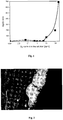
Figure 1 illustrates that Ag can be recovered from solutions containing 1ppb - 250 ppm silver and high Zn concentration. -
Figure 2 is a SEM micrograph illustrating that Pt can be enriched on the surface of 3D carbon from solutions with low Pt concentration (20 ppm Pt) and high Ni concentration (60 g/L Ni). -
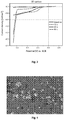
Figure 3 illustrates that the deposit prepared by this method has a catalysing effect on H2 evolution. -
Figure 4 is a SEM micrograph illustrating that both Ag and Pt can be recovered by this method on 3D carbon electrode from solution with low Ag and Pt concentration (20 ppm Pt, 10 ppm Ag) and high Ni concentration (60 g/L Ni). -
Figure 5 illustrates weight-% of (A) Pt and (B) Ag and Pd on the 3D carbon electrode (analysed by SEM-EDX) as a function of deposition time during the electrodeposition step on ED-RR. - One aspect of the present invention is to enable the recovery of Pt and/or Ag from sulfate based solutions, typical for hydrometallurgical base metal production, where Pt and/or Ag is present at low concentrations, without any additional chemical consumption. This is done by an electrodeposition-redox replacement method (ED-RR), which includes
step 1 for electrodeposition andstep 2 for redox replacement, and these steps can be repeated subsequently or following a multistep pattern. - In general, the method of the present invention can be used for recovery of precious metals, which are dissolvable in sulfuric acid, from sulfate media based solutions together with Pt and/or Ag. Especially Pd should be mentioned.
- The term "recovery", as used in the present context,, refers to a recovery of Pt and/ or Ag and together with them, other precious metal which is dissolvable in sulfuric acid from a sulfate based process solution in a form of a deposition on the surface of an electrode. Further, the term is also used in a connection with the recovery (i.e. removal) of the metal from the electrode. In addition, the term "recovery" should be interpreted as follows that at least some of the precious metal is being recovered.
- During ED-RR method, Pt and/or Ag are enriched on the surface of an electrode,
- In the present context the enrichment can be defined as a ratio of a weight-% of the recovered metal on the electrode surface compared to weight-% of it originally in the solution (wt-% of replacement metal on the surface / wt-% of replacement metal originally in the solution). According to a preferred embodiment the enrichment is at least 1 000 fold, more preferably at least 10 000 fold and even more preferably at least 500 000 fold.
- In the present context, the term "sulfate based solutions" or "sulfate based media" designates aqueous solutions which contain sulfate ions. Thus, for example, the terms "sulfate based solutions" or "sulfate based media" stand for solutions of sulfuric acid or obtained from sulfuric acid (which may also be referred to as "spent" acid solutions). Sulfate can also originate from the raw material containing sulfur. Typically, the terms stand for solutions of sulfuric acid used for leaching or otherwise for dissolving metals from raw materials. The "sulfate based solutions" or "sulfate based media" is in particular derived from hydrometallurgical base metal production or hydrometallurgical treatment of secondary raw materials.
- In the present context, "3D", when used in relation to electrodes, designates a conductive material having a non-planar geometry with increased surface area in the micro/nanoscale, being higher than the projected geometrical surface area. Micro- and nanostructuring of the electrode, or stacking of multiple electrodes, is used to increase electrode area and thus, 3D carbon is any carbon material which utilizes micro and nanoscale structures or pores (either fabricated as such or those that form automatically during processing) or their combinations to increase the effective surface area of the carbon electrode.
- An object of the present invention is to provide a method of recovering of Pt and/or Ag from a sulfate based solution containing Zn and/or Ni, such as process solutions from hydrometallurgical plant. Typically, the solution originates form leaching plant for ores or concentrates, Zn electrowinning plant, nickel sulfuric acid leaching plant, electrowinning or electrorefining process, solution purification process, slime treatment process or side-stream treatment process. The sulfate process solution can also originate from leaching of secondary raw materials.
- In one embodiment, the present method is used for recovering Pt or Ag or Pt and Ag from sulfate based process solution rich in sacrificial metal, such as Ni and/or Zn comprising:
- a) step 1: electrodeposition of sacrificial metal such as Zn and/or Ni by applying an external potential or current or pulse potential or pulse current to an electrode placed in a sulfate based process solution;
- b) step 2: a redox replacement of sacrificial metals by the replacement metals, such as Pt or Ag or Pt and Ag, by cutting off the applied external potential or current used in
step 1. Pt or Ag or Pt and Ag present in the solution spontaneously replaces sacrificial metals such as Ni and/or Zn deposited instep 1, resulting in enrichment of Pt or Ag or Pt and Ag on the electrode; - c) optionally repeating steps a) and b) subsequently or by a multistep pattern; and
- d) recovering Pt or Ag or Pt and Ag from the electrode.
- In a preferred embodiment of the invention, cycling between the
electrodeposition step 1 and theredox replacement step 2 takes place. The number of cycles between the ED and RR steps can be varied. Alternatively, multistep pattern can be used instead of simple cycling. After the appropriate number of repetitions ofstep 1 andstep 2, the product rich in Pt and/or Ag is achieved. - Typically, in the present method the Pt and/or Ag enrichment takes place on 3D carbon material, but also such other conductive or semi-conductive electrode materials can be used that do not prevent sacrificial metal deposition such as Ni and/or Zn deposition during
step 1. The electrode(s) are made of any conductive or semi-conductive material to which sacrificial metal can be deposited on. - In a preferred embodiment of the invention,
high surface area 3D carbon is used as the electrode on which the metals are deposited or enriched. - In a preferred embodiment, 3D carbon materials are manufactured through pyrolysis of polymers, primarily photoresists including SU-8. Photoresists of the SU-8 type are epoxy-based negative photoresists. Multiscale roughness can be created by micro- and nanostructuring the polymer films prior to pyrolysis, utilizing for example lithography and embossing techniques. Alternatively, carbon (e.g. glassy carbon or nanotubes) can be machined by, for example, laser; or 3D structures of other materials, like silicon, can be coated by a carbon. Typically at low potentials H2 evolution can compete with sacrificial metal deposition such as Ni and/or Zn deposition. This can limit the use or feasibility of the method. For this
reason 3D carbon electrode is preferred as it widens the electrochemical window and decreases the tendency of H2 disturbance. - The electrode(s) can have any suitable shape, such as plate, ring, sheet, mesh, stick or any other applicable form, present in any configuration related to number of electrodes.
- Surprisingly, it was found out that
high surface area 3D carbon allows good adhesion and good recovery for Pt and Ag in hydrometallurgical sulfate solution (cf. Examples 2 and 4). Example 2 shows that Pt/Ni rich deposit were recovered from a solution with 60 g/L Ni and 20 ppm Pt (10 g/L H2SO4). The Pt/Ni ratio in deposit was approx. 12 on an average. This shows that the present method can be used for recovering Pt from Ni containing sulfate based solutions, typical for hydrometallurgical nickel plants. The present method can also recover multiple valuable metals, Pt and Ag, from sulfate based solution with high Ni content. Example 4 shows that Ag and Pt can be recovered simultaneously on 3D carbon with this method. The average composition of the recovered metal (Table 2 in Example 4) shows that the quality of recovery is good, with high Pt+Ag/Ni ratio (ca. 27). - Traditionally, Pt and Ag present in hydrometallurgical sulfate based process solutions are not recovered as a Pt and/or Ag rich product, but are wasted or diluted into base metal, solutions, acids, sidestreams or products due to low concentrations of Pt and/or Ag present in the solution. The present invention outstandingly shows the possibility to recovery Pt and/or Ag from very low concentrations, even as low as 1 ppb (Example 1). Example 1 shows that Ag present at very low quantity (1 ppb, 50 ppb, 500 ppb, 1 ppm) can be recovered from Zn containing solution on Pt electrode using this method. This is a novel feature, since such low values are not typically recovered from hydrometallurgical process solutions. This finding is even more remarkable considering that the typical base metal concentration is high (in the present case Zn), typically >20 g/L.
- It is also noteworthy that the replacement metal content (Pt or Ag) can be below detection limit of typical analysis methods such as AAS, ICP-OES.
- Therefore, considerable advantages are achieved by the method of the present invention. The fact that Pt and/or Ag present in hydrometallurgical process solutions at low concentration (1 ppb - 20 ppm) can be recovered is notable.
- Also the fact that the Pt and/or Ag containing electrode, prepared using the present method, provides a catalyzing effect is notable (Example 3). Therefore, the method can be used to prepare catalytic surfaces from hydrometallurgical sulfate based solutions which have low concentrations of Pt or Ag or Pt and Ag and high concentration of base metals (such as Ni or Zn). It is remarkable, that these kind of impure hydrometallurgical process solutions with low Pt and/or Ag and high Ni and/or Zn concentration have not earlier been used for preparing catalyzing surface materials or deposits.
- The recovery of Pt and/or Ag, present at levels as low as 1 ppb, from hydrometallurgical process solutions, has been challenging and economically unfeasible with current methods such as ion exchange. One advantage of the method according to the present invention is that the energy used for Zn and/or Ni deposition during electrodeposition step is utilized for spontaneous replacement reaction by Pt and/or Ag vs. base metals such as Ni and/or Zn, which can take place without external current or potential. A further advantage of the method is that no additional chemical is needed for Pt and/or Ag recovery and no additional precipitation agents such as NaHS is subjected into the process solution in this stage. Pt and/or Ag recovered by the method of the invention can be used as raw material for a precious metal plant, or further enriched by chemical or electrochemical oxidation and further recovery, or used as a catalyst surface. The obtained deposit on the electrode can be subjected to leaching, a hydrometallurgical method, a pyrometallurgical method, chemical stripping, physical stripping or electrochemical stripping for recovering Pt and/or Ag from the electrode.
- In an embodiment, the present technology provides for the use of an electrodeposition-redox replacement cycling method (ED-RR) for recovery of Pt and/or Ag from sulfate based process solutions. Pt and/or Ag, are usually present at low quantities in sulfate based solution.
- The method comprises of two steps: (step 1) electrodeposition of sacrificial metal such as Zn and/or Ni by applying an external potential or current or potential pulses or current pulses to an electrode placed in sulfate based process solution and (step 2) a redox replacement by the replacement metals such as Pt and/or Ag by cutting off the applied external potential or current used in
step 1. Instep 2 Pt and/or Ag present in solution spontaneously replaces sacrificial metals such as Ni and/or Zn deposited instep 1, resulting in enrichment of Pt and/or Ag on the electrode. -
Electrodeposition step 1 is conducted at a constant current, at a constant potential, pulsing the current, pulsing the potential, or by varying the potential or current in a range in which sacrificial metal deposits on the electrode. The potential in the electrodeposition step is such that sacrificial metal can deposit on the electrode and hydrogen evolution does not prevent the metal recovery. -
Redox replacement step 2 can be conducted by cutting-off the applied potential or current or reducing the current or potential to such a low value that the spontaneous replacement of sacrificial metals such as Zn and/or Ni by the replacement metals such as Pt or Ag or Pt and Ag can take place. - In the present method the recovery is typically performed by repeating step1 and step2. The electrodeposition (step 1) and redox replacement steps (step 2) are typically repeated 1 - 50 000 times, more typically 1-5 000 times, even more typically 10-1000 times, and still more typically 10 - 500 times, before recovering (removing) the replacement metals from the electrode. Not all these repetitions need to be identical, but the
step 1 and step 2 parameters can be varied during the method. Also, it is possible to stop any of the steps while the step is still ongoing. The repetition of steps can also be stopped either afterstep 1 orstep 2. It is also possible to haveseveral step 1 before thestep 2 and vice versa. The method can be finished after or during any of the steps. - In
step 1, external current or potential is applied to enable the deposition for a predetermined time. Also pulsing of the current or potential duringstep 1 can be conducted. - According to one embodiment, during
step 1, the cathodic potential is preferably less than 0 V vs. SCE (saturated calomel electrode), typically in the range from 0 or less than 0 to -2.0 V vs. SCE, more typically between 0.0 V and -1.2 V vs. SCE, and even more typically between -0.3 V and -1.2 V vs. SCE. Ifstep 1 is performed by potential pulsing between two or more potentials, the most negative pulsing potential is less than 0 V vs. SCE (saturated calomel electrode), typically between 0 and -2.0 V vs. SCE, more typically between 0.0 V and -1.2 V vs. SCE, and even more typically between - 0.3 V and -1.2 V vs. SCE. The other pulsing potentials can be any potential higher than this most negative potential. - According to another embodiment, during
step 1, the cathodic potential is preferably less than 0 V vs. SCE (saturated calomel electrode), typically in the range from 0 or less than 0 to -2.0 V vs. SCE, more typically between 0.0 V and -1.0 V vs. SCE, and even more typically between -0.3 V and -0.6 V vs. SCE. Ifstep 1 is performed by potential pulsing between two or more potentials, the most negative pulsing potential is less than 0 V vs. SCE (saturated calomel electrode), typically between 0 and -2.0 V vs. SCE, more typically between 0.0 V and -1.0 V vs. SCE, and even more typically between - 0.3 V and -0.6 V vs. SCE. The other pulsing potentials can be any potential higher than this most negative potential. - If the deposition is conducted by applying external current, the absolute value of the current density is in the range of 0.01-1000 mA/cm2, typically 0.01-300 mA/cm2, more typically 0.01-200 mA/cm2, even more typically 0.01-100 mA/cm2.
Step 1 has a residence time, which is in the range of 0.01 s to 10 min, more typically 0.01 s to 30 s, or even more typically 0.01 to 10 s. - In
step 2 no external current or potential is applied. Optionally instep 2, current density close to corrosion current density or potential close to open circuit potential (OCP) is applied in such a way that redox replacement still can take place. Corrosion current density is the indicated current density due to the spontaneous corrosion/leaching of the electrode in the absence of external current. OCP is the electrode potential measured when no external current or potential is applied: OCP is influenced by the solution composition and activities of species present, electrode|solution interface, electrode reactions, electrode material, temperature, pressure, additives and other process parameters. -
Step 2 is finished after a pre-determined time or when the open circuit potential value reaches a pre-determined value, which is typically just below stripping potential of the replacement metal. This potential is below 0.6 V vs. SCE, typically below 0.4 V vs. SCE, more typically below 0.35 V vs. SCE, however at potential higher than deposition potential of sacrificial metal. The time ofstep 2 i.e cut-off time is such that it allows replacing the sacrificial metal such as Zn and/or Ni with the replacement metals such as Pt and/or Ag to take place, typically less than 48 hours, more typically 3 s - 24 hours, even more typically 3 s - 2 h, even more typically 3 s - 30 min. Very low Pt and/or Ag concentrations typically demandhigher step 2 time i.e. cut-off time. - The present method is typically applied to Pt and/or Ag recovery from sulfate based solution. Typically Pt and/or Ag as the replacement metals are present in solution in small quantities. The recovery takes place in sulfate based solution wherein the replacement metal (Pt and/or Ag) content is <25 ppm, typically <10 ppm, even more typically <1 ppm, even more typically <0.5 ppm. The replacement metal content (Pt and/or Ag) can be also below detection limit of typical analysis methods such AAS, ICP-OES. This is a special feature of this method - the method can be used for recovery in solution having extremely low concentrations of Pt and/or Ag. This is truly remarkable as solutions with this low concentrations of Pt and/or Ag are not typically utilized for metal recovery. Typically the sacrificial metal is Zn and/or Ni. The sacrificial metal concentration is >2 g/l, typically >5 g/l, more typically >20 g/l and even more typically >40 g/l.
- Typically, the method is used in solutions in which the concentration ratio between sacrificial metal (typically Zn and/or Ni) and the replacement metal (typically Pt and/or Ag) is typically >100, more typically >1000, even more typically >10000. The method comprises or consists of the use of an electrodeposition-redox replacement method (ED-RR) for recovery of Pt or Ag or Pt and Ag from sulfate based process solutions.
- Typically, sulfate based process solution rich in sacrificial base metal has sulfate content higher than 0.1 M, more typically higher than 0.3 M, even more typically higher than 0.5 M. The sulfate based process solution can also contain other elements, such as Bi, Cu, Pb, Pd, Sn, Te, Se, Co, Na, Ca, Mg, K.
- As already mentioned earlier, especially Pd, of these other elements, present in the process solution at a small concentration can be recovered with the method of the present invention. Pd is metal useful in catalysts and thus, according to one embodiment can also be used to prepare catalytic surfaces according to the present method.
- Recovery of Pd together with Pt and Ag is illustrated in Example 5, wherein these are enriched/ recovered by ED-RR from an industrial sulfate based solution on an electrode surface.
- Sulfate based process solutions typically originate from hydrometallurgical process such leaching process for ores or concentrates, electrowinning or electrorefining process, solution purification process, slime treatment process or side-stream treatment process. Sulfate based process solution can also originate from leaching of secondary raw materials.
- The method of the present invention can be applied for removal, for recovery and/or both for removal and recovery Pt and/or Ag or their metal complexes or compounds from sulfate based process solution. Sulfate based process solutions in this context refer to any Zn and/or Ni and Pt and/or Ag bearing aqueous sulfate based process solution or side stream or waste solution or waste acid that originates from a hydrometallurgical process plant processing primary or secondary raw materials, more typically primary raw materials such as ores or concentrates. Typically, these solutions have a low pH, typically pH below 5.
- In the sulfate based process solution, Pt and Ag are typically present in minor amounts, as soluble ions or complexes. The complexes may form with any of the solution species present in the solution or added to the solution.
- The process solution can be continuously flowing, stagnant, stirred or pumped when the method is applied. The method can be applied as a continuous process or as a batch process. The method can be applied at the base metal plant, recycling plant or at accompanied plant or even at remote locations.
- In order to recover Pt and/or Ag from sulfate based process solution, electrodes are immersed into the solution in a suitable vessel, pool, tank etc. or in-situ in the plant, in the accompanied plant, outlet solution etc., and repeating electrodeposition and redox replacement steps.
- In one embodiment, the present method is carried out using a three-electrode set-up (working electrode (WE) = electrode at which the product is formed; counter electrode (CE) and reference electrode (RE)) or in two-electrode set-up (working electrode (WE) and counter electrode (CE)).
- After performing this method, Pt and/or Ag (and other metals, such as Pd) can be recovered from the electrode by methods known by person skilled in art. The electrode obtained after step1 or after
step 2, or after repeatingsteps 1 and 2 a number of times, is subjected to leaching, a hydrometallurgical method, a pyrometallurgical method, chemical stripping, physical stripping or electrochemical stripping for recovering Pt and/or Ag from the electrode. - According to another embodiment the electrode obtained after
step 1 or afterstep 2, or after repeatingsteps 1 and 2 a number of times, can be used as such for example as a catalytic surface. - In this example platinum electrode was subjected to ED-RR in solution containing 60 g/L Zn, and 10 g/L H2SO4. The silver content in the solution varied between 1 ppb - 250 ppm. The electrodeposition potential in
step 1 was -0.7 V (vs. SCE) and the cut-off potential for the redox replacement (in step 2) was +0.3 V (vs. SCE). The used deposition time instep 1 was 10 s. Thestep 1 andstep 2 were cycled 10 times.Figure 1 shows that Ag can be recovered on Pt electrode with this method. The resulting deposit has over five times more Ag than Zn (in solution with 1 ppb Ag, 60 g/L Zn). The ratio between deposited Ag and Zn increases exponentially as a function of Ag content in the original solution, as seen in Table 1. This result shows that this method can be used for recovery of silver from solutions containing very low amounts of silver.Table 1.Effect of the Ag content in the solution on the content of the deposit. Ag content in the solution Zn (wt-%) Ag (wt-%) Ag/ Zn 1 ppb 0.03 0.18 5.7 50 ppb 0.04 1.10 29 500 ppb 0.03 0.33 10 1000 ppb 0.13 0.33 2.5 2 ppm 0.15 0.53 3.4 5 ppm 0.20 0.84 4.2 10 ppm 0.07 4.94 71 100 ppm 0.08 14.30 191 250 ppm 0.06 38.67 685 - In this example 3D carbon electrode was subjected to ED-RR in solution containing 60 g/L Ni, 20 ppm Pt, and 10 g/L H2SO4. The electrodeposition potential in
step 1 was -0.6 V (vs. SCE) and the cut-off potential for the redox replacement (in step 2) was + 0.4 V (vs. SCE). The used deposition time instep 1 was 10 s. Thestep 1 andstep 2 were cycled 10 times. -
Figure 2 shows SEM micrograph of the deposited Pt/Ni on the surface of 3D carbon. The Pt/Ni ratio was determined by SEM-EDX and it was approx. 12 in average. The highest analyzed deposit fraction of Pt was 98 wt-% whereas the highest analyzed Ni was maximum 14.5 wt-%. This shows that using this method Pt can be recovered effectively on 3D-carbon electrode. - In this example 3D carbon electrode was subjected to ED-RR in solution containing 60 g/L Ni, 20 ppm Pt and 10 g/L H2SO4. The electrodeposition potential in
step 1 was -0.6 V (vs. SCE) and the cut-off potential for the redox replacement (in step 2) was + 0.4 V (vs. SCE). The used deposition times instep 1 were 10 - 60 s. Thestep 1 andstep 2 were cycled 10 times. The Pt/Ni ratios of the deposit on the 3D-carbon electrode after ED-RR were determined by SEM-EDX and they were 71.7 (with 10 s deposition time in step 1), 33.6 (with 30 s deposition time in step 1) and 36.8 (with 60s deposition time in step 1). - The catalyzing effects of the deposits were investigated in 0.1 M H2SO4 media,
Figure 3 . Linear sweep voltammetry was measured from 0.8 V (vs. SCE) to the cathodic direction with scan rate of 20 mV/s. - The hydrogen evolution of 3D carbon without deposit started at -1.0 V (vs. SCE), while after using this method (ED-RR) the hydrogen evolution started at -0.3 V (vs. SCE). This shows that the Pt/Ni deposits prepared by this method on 3D carbon surface have a catalyzing effect on hydrogen evolution.
- In this example 3D carbon electrode was subjected to ED-RR in solution containing 60 g/L Ni, 20 ppm Pt, 10 ppm Ag and 10 g/L H2SO4. The electrodeposition potential in
step 1 was -0.6 V (vs. SCE) and the cut-off potential for the redox replacement (in step 2) was + 0.4 V (vs. SCE). The used deposition time instep 1 was 10 s. Thestep 1 andstep 2 were cycled 20 times.Figure 4 shows SEM micrograph of the deposit on 3D carbon. Table 2 shows that Ag and Pt can be recovered on 3D carbon electrode with this method.Table 2. Content of the deposit on 3D carbon. C (wt-%) Ni (wt-%) Ag (wt-%) Pt (wt-%) 75.08 0.88 0.96 23.08 - Table 3 shows the solution composition (real industrial sulfate based process solution) and
Figure 5 shows the recovered metal composition from this solution using ED-RR (weight-% of recovered Pt, Ag and Pd on the electrode deposit, analysed by SEM-EDX). Electrodeposition potential used was -175 mV vs. SCE and cut-off potential for the redox replacement step was +350 mV vs. SCE. Number of cycles was 10. - It can be seen that the Pt, Ag and Pd can be successfully enriched/recovered by ED-RR from industrial sulfate based solutions on the electrode surface. It is notable, that although the industrial sulfate based solution contains Pt even below the detection limit, it is still the dominating element of the metal deposit recovered successfully (
Figure 5A ). Importantly, also Ag and Pd can be enriched on the electrode, although they are present in industrial solution at very small concentrations (Figure 5B ).Table 3. Solution composition. Element Al As Cu Fe Ni Pb Zn Content in the solution ppm ppm ppm ppm ppm ppm ppm 24.8 767 5850 15900 141000 40 236 Element Sn Ga Ge In Cd Ag Au Pd Pt Content in the solution ppb ppb ppb ppb ppb ppb ppb ppb ppb 227.5 147.5 2864 999.7 203.5 5.9 <LOD 88.6 <LOD (1.0*) LOD = Limit of detection, * value below detection limit -
- EDRR
- electrodeposition-redox replacement
- WE
- working electrode
- CE
- counter electrode
- RE
- reference electrode
- SCE
- saturated calomel electrode
- LOD
- limit of detection
- 3D
- three-dimensional
-
- S.R. Brankovic, J.X. Wang, R.R. Adžić, "Metal monolayer deposition by replacement of metal adlayers on electrode surfaces" Surface Science, 474 (2001), p. L173.
- Nikolay Dimitrov, Recent Advances in the Growth of Metals, Alloys, and Multilayers by Surface Limited Redox Replacement (SLRR) Based Approaches, Electrochimica Acta 209 (2016) 599-622.
- Robert E. Rettew James W. Guthrie, Cherno Jaye, Daniel Fischer, Faisal M. Alamgir, Synthesis and Characterization of Monolayer Bimetallic Surfaces: A Synchrotron NEXAFS and XPS Study, ECS Transactions 19 (2009) 97-106.
- R.E. Rettew, J.W. Guthrie, F.M. Alamgir, Journal of the Electrochemical Society 156 (2009) D513.
- Wouter Maijenburg, Antony George, D. Sama1, Maarten Nijland, Rogier Besselink, Bouwe Kuiper, Josée E. Kleibeuker, Johan E. ten Elshof, Electrodeposition of micropatterned Ni|Pt multilayers and segmented Ni|Pt|Ni nanowires, Electrochimica Acta 81 (2012) 123- 128.
- S. Papadimitriou, S. Armyanov, E. Valova, A. Hubin, O. Steenhaut, E. Pavlidou, G. Kokkinidis, S. Sotiropoulos, Journal of Physical Chemistry C 114 (2010) 5217.
- S. Papadimitriou, A. Tegou, E. Pavlidou, S. Armyanov, E. Valova, G. Kokkinidis, S. Sotiropoulos, Electrochimica Acta 53 (2008) 6559.
- A. Tegou, S. Armyanov, E. Valova, O. Steenhaut, A. Hubin, G. Kokkinidis, S. Sotiropoulos, Journal of Electroanalytical Chemistry 634 (2009) 104.
- A. Tegou, S. Papadimitriou, G. Kokkinidis, S. Sotiropoulos, Journal of Solid State Electrochemistry 14 (2010) 175.
Claims (15)
- A method of recovering Pt or Ag or Pt and Ag from sulfate based process solution rich in sacrificial metal comprising:a) step 1: electrodeposition of sacrificial metal on an electrode by applying an external potential or current or pulse potential or pulse current to the electrode placed in a sulfate based process solution;b) step 2: a redox replacement of sacrificial metals by a replacement metal, selected from the group of Pt or Ag or Pt and Ag, by cutting off or reducing the applied external potential or current used in step 1, wherein Pt or Ag or Pt and Ag present in the solution spontaneously replaces sacrificial metals deposited in step 1, resulting in enrichment of Pt or Ag or Pt and Ag on the electrode;c) optionally repeating steps a) and b) subsequently or by a multistep pattern; andd) recovering Pt or Ag or Pt and Ag from the electrode or using the deposition containing electrode as such.
- The method according to claim 1, wherein the sacrificial metal is Ni and/or Zn.
- The method according to any of the preceding claims, wherein sulfate based process solution contains other elements, preferably Bi, Cu, Pb, Pd, Sn, Te, Se, Co, Na, Ca, Mg, K or combinations thereof.
- The method according to any of the preceding claims, wherein Pd is recovered together with Pt or Ag or Pt and Ag on the electrode from the sulfate based process solution.
- The method according to any of the preceding claims wherein the recovery takes place in sulfate based solution wherein the replacement metal content is <25 ppm, preferably <10 ppm, more preferably <1 ppm, even more preferably <0.5 ppm.
- The method according any of the preceding claims, wherein the replacement metal content is below detection limit of analysis methods AAS and ICP-OES.
- The method according to any of the preceding claims, wherein the sulfate based solution has a sacrificial metal concentration of >2 g/l, preferably >5 g/l, more preferably >20 g/l and even more preferably >40 g/l.
- The method according to any of the preceding claims, wherein the electrode(s) are made of any conductive or semi-conductive material onto which sacrificial metal can be deposited and, wherein the electrode(s) preferably have the shape of a plate, ring, sheet, mesh, or stick, present in any configuration related to number of electrodes.
- The method according to any of the preceding claims, wherein the electrode(s) are made of 3D carbon material, which is preferably fabricated through pyrolysis of polymers, primarily photoresists including SU-8, and preferably multiscale roughness of the electrode is created spontaneously during pyrolysis of polymers, primarily photoresists including SU-8, or by micro- and nanostructuring of the polymer films prior to pyrolysis, utilizing lithography and embossing techniques, or alternatively, carbon, preferably glassy carbon or nanotubes, is machined by laser, or 3D structures of other materials, preferably silicon, are coated by a carbon.
- The method according to any of the preceding claims, wherein the electrodeposition step in claim 1 a) is conducted at a constant current, at a constant potential, pulsing the current, pulsing the potential, or by varying the potential or current in a range in which sacrificial metal deposits on the electrode, and wherein the electrodeposition step a) preferably has a residence time, which is in the range of 0.01 s-10 min, more preferably 0.01 s-30 s, or even more preferably 0.01-10 s,
- The method according to any one of the preceding claims, wherein the potential in the electrodeposition step is such that sacrificial metal can deposit on the electrode and hydrogen evolution does not prevent the metal recovery, wherein the electrodeposition step in claim 1 a) is performed by potential pulsing between two or more potentials, where the cathodic potential, i.e. the most negative pulsing potential, is less than 0 V vs. SCE (saturated calomel electrode), preferably in between 0 and -2.0 V vs. SCE, more preferably between 0.0 V and -1.2 V vs. SCE, and even more preferably between -0.3 V and -1.2 V vs. SCE, while the other pulsing potential is any potential higher than this most negative potential.
- The method according to any one of the preceding claims, wherein the absolute value of the externally applied current density in the electrodeposition step in the claim 1 a) is in the range of 0.01 - 1000 mA/cm2, preferably 0.01 - 300 mA/cm2, more preferably 0.01 - 200 mA/cm2, even more preferably 0.01- 100 mA/cm2.
- The method according to any one of the preceding claims, wherein the redox replacement step b) is finished after a pre-determined time period that allows replacing the sacrificial metal with the replacement metals, preferably after less than 48 hours, more preferably after 3 s - 24 hours, even more preferably after 3 s - 2 h, most preferably after 3 s - 30 min, or when the open circuit potential value reaches a pre-determined value, which is below 0.6 V vs. SCE, preferably below 0.4 V vs. SCE, more preferably below 0.35 V vs. SCE, however at potential higher than deposition potential of sacrificial metal.
- The method according to any one of the preceding claims, wherein electrodeposition and redox replacement steps in claim 1 are repeated 1 - 50 000 times, preferably 1 - 5 000 times, more preferably 10 - 1000 times, and even more preferably 10 - 500 times, before recovering the replacement metals from the electrode, and wherein the method is finished after or during any of the steps.
- Use of an electrodeposition-redox replacement method (ED-RR) according to any of the preceding claims for recovery of Pt or Ag or Pt and Ag and Pd from sulfate based process solutions.
Priority Applications (1)
| Application Number | Priority Date | Filing Date | Title |
|---|---|---|---|
| PL18739573T PL3642395T3 (en) | 2017-06-22 | 2018-06-20 | A method of recovering pt or ag or pt and ag from sulfate based metal solutions |
Applications Claiming Priority (2)
| Application Number | Priority Date | Filing Date | Title |
|---|---|---|---|
| FI20175591 | 2017-06-22 | ||
| PCT/FI2018/050484 WO2018234637A1 (en) | 2017-06-22 | 2018-06-20 | PROCESS FOR RECOVERING PT OR AG OR PT AND AG FROM SULFATE-BASED METALLIC SOLUTIONS |
Publications (2)
| Publication Number | Publication Date |
|---|---|
| EP3642395A1 EP3642395A1 (en) | 2020-04-29 |
| EP3642395B1 true EP3642395B1 (en) | 2021-05-05 |
Family
ID=62873367
Family Applications (1)
| Application Number | Title | Priority Date | Filing Date |
|---|---|---|---|
| EP18739573.6A Active EP3642395B1 (en) | 2017-06-22 | 2018-06-20 | A method of recovering pt or ag or pt and ag from sulfate based metal solutions |
Country Status (6)
| Country | Link |
|---|---|
| US (1) | US11486047B2 (en) |
| EP (1) | EP3642395B1 (en) |
| ES (1) | ES2877603T3 (en) |
| PL (1) | PL3642395T3 (en) |
| WO (1) | WO2018234637A1 (en) |
| ZA (1) | ZA202000284B (en) |
Families Citing this family (1)
| Publication number | Priority date | Publication date | Assignee | Title |
|---|---|---|---|---|
| CN112342572B (en) * | 2020-09-21 | 2022-02-15 | 万华化学集团股份有限公司 | A kind of recovery treatment method of low concentration platinum in organic waste liquid |
Family Cites Families (3)
| Publication number | Priority date | Publication date | Assignee | Title |
|---|---|---|---|---|
| FR2467887A1 (en) | 1979-10-23 | 1981-04-30 | Kodak Pathe | PROCESS FOR THE RECOVERY OF A METAL FROM AQUEOUS SOLUTIONS, BY EXCHANGE WITH A SECOND REDUCING METAL |
| WO2009097480A2 (en) | 2008-01-30 | 2009-08-06 | The Regents Of The University Of California | Near infra-red pulsed laser triggered drug release from hollow nanoshell disrupted vesicles and vesosomes |
| KR20140035701A (en) | 2012-09-14 | 2014-03-24 | 삼성전기주식회사 | Method fo forming au thin-film and printed circuit board |
-
2018
- 2018-06-20 WO PCT/FI2018/050484 patent/WO2018234637A1/en not_active Ceased
- 2018-06-20 ES ES18739573T patent/ES2877603T3/en active Active
- 2018-06-20 EP EP18739573.6A patent/EP3642395B1/en active Active
- 2018-06-20 PL PL18739573T patent/PL3642395T3/en unknown
- 2018-06-20 US US16/624,993 patent/US11486047B2/en active Active
-
2020
- 2020-01-15 ZA ZA2020/00284A patent/ZA202000284B/en unknown
Also Published As
| Publication number | Publication date |
|---|---|
| ES2877603T3 (en) | 2021-11-17 |
| PL3642395T3 (en) | 2021-10-18 |
| WO2018234637A1 (en) | 2018-12-27 |
| EP3642395A1 (en) | 2020-04-29 |
| ZA202000284B (en) | 2021-08-25 |
| US11486047B2 (en) | 2022-11-01 |
| US20200141016A1 (en) | 2020-05-07 |
Similar Documents
| Publication | Publication Date | Title |
|---|---|---|
| US11072864B2 (en) | Systems and methods for continuous alkaline lead acid battery recycling | |
| Halli et al. | Electrochemical recovery of tellurium from metallurgical industrial waste | |
| AU2009345105B2 (en) | Anode structure for copper electrowinning | |
| RS62200B1 (en) | Closed loop systems and methods for recycling lead acid batteries | |
| EP4098775A1 (en) | Cathode electrode, complex of cathode electrode and substrate, and method for manufacturing complex of cathode electrode and substrate | |
| DE102015203245A1 (en) | Deposition of a copper-containing, hydrocarbon-developing electrocatalyst on non-copper substrates | |
| CA2821042A1 (en) | Gold and silver electrorecovery from thiosulfate leaching solutions | |
| Halli et al. | Improved metal circular economy-selective recovery of minor Ag concentrations from Zn process solutions | |
| US10934192B2 (en) | Method of recovering copper from a dilute metal containing solution | |
| US11486047B2 (en) | Method of recovering Pt or Ag or Pt and Ag from sulfate based metal solutions | |
| FR2479275A1 (en) | PROCESS FOR THE ELECTRODEPOSITION OF COPPER | |
| US20140076735A1 (en) | Electrorecovery of gold and silver from leaching solutions by simultaneous cathodic and anodic deposits | |
| WO2017153547A1 (en) | Electrolytic refinement of raw gold | |
| US10287694B2 (en) | Amalgam electrode, method for manufacturing the same, and method for electrochemical reduction of carbon dioxide using the same | |
| US4026786A (en) | Preparation of PbO2 anode | |
| Wang | Targeted preparation of metallic materials via innovative electrochemical approaches | |
| EP1626098A2 (en) | Process of dissolving zinc in alkaline brines | |
| EP4007824A1 (en) | Metal recovery from lead containing electrolytes | |
| WO2017216417A1 (en) | A method of recovering gold from a gold-bearing concentrated copper chloride solution | |
| Sorour | Organic addittives in zinc electrowinning and electrodeposition of Fe-Mo-P alloys as cathodes for chlorate production | |
| CN118479479A (en) | Method for recycling tungsten carbide and cobalt from waste hard alloy through bidirectional pulse electrolysis | |
| EP0588149A1 (en) | Process for the electrochemical dissociation of alkali sulfates and ammonium sulfate in free alkali and sulfuric acid with simultaneous anodic oxidation of sulfur dioxide | |
| He et al. | Zinc electroplating in the zinc oxide-urea-1-ethyl-3-methylimidazolium chloride system at 333 K to 363 K | |
| KR20160097176A (en) | Amalgam electrode, preparing method thereof, and method of electrochemical reduction of carbon dioxide using the same | |
| DE10060127A1 (en) | Electrolytic iron deposition bath used for forming iron layers in the automobile industry, in microsystems and in circuit board manufacture contains iron alkane sulfonate as an iron ion source, an acid former and a solvent |
Legal Events
| Date | Code | Title | Description |
|---|---|---|---|
| STAA | Information on the status of an ep patent application or granted ep patent |
Free format text: STATUS: UNKNOWN |
|
| STAA | Information on the status of an ep patent application or granted ep patent |
Free format text: STATUS: THE INTERNATIONAL PUBLICATION HAS BEEN MADE |
|
| PUAI | Public reference made under article 153(3) epc to a published international application that has entered the european phase |
Free format text: ORIGINAL CODE: 0009012 |
|
| STAA | Information on the status of an ep patent application or granted ep patent |
Free format text: STATUS: REQUEST FOR EXAMINATION WAS MADE |
|
| 17P | Request for examination filed |
Effective date: 20200121 |
|
| AK | Designated contracting states |
Kind code of ref document: A1 Designated state(s): AL AT BE BG CH CY CZ DE DK EE ES FI FR GB GR HR HU IE IS IT LI LT LU LV MC MK MT NL NO PL PT RO RS SE SI SK SM TR |
|
| AX | Request for extension of the european patent |
Extension state: BA ME |
|
| DAV | Request for validation of the european patent (deleted) | ||
| DAX | Request for extension of the european patent (deleted) | ||
| GRAP | Despatch of communication of intention to grant a patent |
Free format text: ORIGINAL CODE: EPIDOSNIGR1 |
|
| STAA | Information on the status of an ep patent application or granted ep patent |
Free format text: STATUS: GRANT OF PATENT IS INTENDED |
|
| INTG | Intention to grant announced |
Effective date: 20201211 |
|
| GRAS | Grant fee paid |
Free format text: ORIGINAL CODE: EPIDOSNIGR3 |
|
| GRAA | (expected) grant |
Free format text: ORIGINAL CODE: 0009210 |
|
| STAA | Information on the status of an ep patent application or granted ep patent |
Free format text: STATUS: THE PATENT HAS BEEN GRANTED |
|
| AK | Designated contracting states |
Kind code of ref document: B1 Designated state(s): AL AT BE BG CH CY CZ DE DK EE ES FI FR GB GR HR HU IE IS IT LI LT LU LV MC MK MT NL NO PL PT RO RS SE SI SK SM TR |
|
| REG | Reference to a national code |
Ref country code: GB Ref legal event code: FG4D |
|
| REG | Reference to a national code |
Ref country code: CH Ref legal event code: EP |
|
| REG | Reference to a national code |
Ref country code: AT Ref legal event code: REF Ref document number: 1389920 Country of ref document: AT Kind code of ref document: T Effective date: 20210515 |
|
| REG | Reference to a national code |
Ref country code: DE Ref legal event code: R096 Ref document number: 602018016766 Country of ref document: DE |
|
| REG | Reference to a national code |
Ref country code: IE Ref legal event code: FG4D |
|
| REG | Reference to a national code |
Ref country code: FI Ref legal event code: FGE |
|
| REG | Reference to a national code |
Ref country code: SE Ref legal event code: TRGR |
|
| REG | Reference to a national code |
Ref country code: NO Ref legal event code: T2 Effective date: 20210505 |
|
| REG | Reference to a national code |
Ref country code: LT Ref legal event code: MG9D |
|
| REG | Reference to a national code |
Ref country code: AT Ref legal event code: MK05 Ref document number: 1389920 Country of ref document: AT Kind code of ref document: T Effective date: 20210505 |
|
| PG25 | Lapsed in a contracting state [announced via postgrant information from national office to epo] |
Ref country code: HR Free format text: LAPSE BECAUSE OF FAILURE TO SUBMIT A TRANSLATION OF THE DESCRIPTION OR TO PAY THE FEE WITHIN THE PRESCRIBED TIME-LIMIT Effective date: 20210505 Ref country code: LT Free format text: LAPSE BECAUSE OF FAILURE TO SUBMIT A TRANSLATION OF THE DESCRIPTION OR TO PAY THE FEE WITHIN THE PRESCRIBED TIME-LIMIT Effective date: 20210505 Ref country code: BG Free format text: LAPSE BECAUSE OF FAILURE TO SUBMIT A TRANSLATION OF THE DESCRIPTION OR TO PAY THE FEE WITHIN THE PRESCRIBED TIME-LIMIT Effective date: 20210805 Ref country code: AT Free format text: LAPSE BECAUSE OF FAILURE TO SUBMIT A TRANSLATION OF THE DESCRIPTION OR TO PAY THE FEE WITHIN THE PRESCRIBED TIME-LIMIT Effective date: 20210505 |
|
| REG | Reference to a national code |
Ref country code: ES Ref legal event code: FG2A Ref document number: 2877603 Country of ref document: ES Kind code of ref document: T3 Effective date: 20211117 |
|
| PG25 | Lapsed in a contracting state [announced via postgrant information from national office to epo] |
Ref country code: RS Free format text: LAPSE BECAUSE OF FAILURE TO SUBMIT A TRANSLATION OF THE DESCRIPTION OR TO PAY THE FEE WITHIN THE PRESCRIBED TIME-LIMIT Effective date: 20210505 Ref country code: PT Free format text: LAPSE BECAUSE OF FAILURE TO SUBMIT A TRANSLATION OF THE DESCRIPTION OR TO PAY THE FEE WITHIN THE PRESCRIBED TIME-LIMIT Effective date: 20210906 Ref country code: LV Free format text: LAPSE BECAUSE OF FAILURE TO SUBMIT A TRANSLATION OF THE DESCRIPTION OR TO PAY THE FEE WITHIN THE PRESCRIBED TIME-LIMIT Effective date: 20210505 Ref country code: IS Free format text: LAPSE BECAUSE OF FAILURE TO SUBMIT A TRANSLATION OF THE DESCRIPTION OR TO PAY THE FEE WITHIN THE PRESCRIBED TIME-LIMIT Effective date: 20210905 Ref country code: GR Free format text: LAPSE BECAUSE OF FAILURE TO SUBMIT A TRANSLATION OF THE DESCRIPTION OR TO PAY THE FEE WITHIN THE PRESCRIBED TIME-LIMIT Effective date: 20210806 |
|
| REG | Reference to a national code |
Ref country code: NL Ref legal event code: MP Effective date: 20210505 |
|
| PG25 | Lapsed in a contracting state [announced via postgrant information from national office to epo] |
Ref country code: NL Free format text: LAPSE BECAUSE OF FAILURE TO SUBMIT A TRANSLATION OF THE DESCRIPTION OR TO PAY THE FEE WITHIN THE PRESCRIBED TIME-LIMIT Effective date: 20210505 |
|
| PG25 | Lapsed in a contracting state [announced via postgrant information from national office to epo] |
Ref country code: EE Free format text: LAPSE BECAUSE OF FAILURE TO SUBMIT A TRANSLATION OF THE DESCRIPTION OR TO PAY THE FEE WITHIN THE PRESCRIBED TIME-LIMIT Effective date: 20210505 Ref country code: SK Free format text: LAPSE BECAUSE OF FAILURE TO SUBMIT A TRANSLATION OF THE DESCRIPTION OR TO PAY THE FEE WITHIN THE PRESCRIBED TIME-LIMIT Effective date: 20210505 Ref country code: CZ Free format text: LAPSE BECAUSE OF FAILURE TO SUBMIT A TRANSLATION OF THE DESCRIPTION OR TO PAY THE FEE WITHIN THE PRESCRIBED TIME-LIMIT Effective date: 20210505 Ref country code: DK Free format text: LAPSE BECAUSE OF FAILURE TO SUBMIT A TRANSLATION OF THE DESCRIPTION OR TO PAY THE FEE WITHIN THE PRESCRIBED TIME-LIMIT Effective date: 20210505 Ref country code: SM Free format text: LAPSE BECAUSE OF FAILURE TO SUBMIT A TRANSLATION OF THE DESCRIPTION OR TO PAY THE FEE WITHIN THE PRESCRIBED TIME-LIMIT Effective date: 20210505 Ref country code: RO Free format text: LAPSE BECAUSE OF FAILURE TO SUBMIT A TRANSLATION OF THE DESCRIPTION OR TO PAY THE FEE WITHIN THE PRESCRIBED TIME-LIMIT Effective date: 20210505 |
|
| REG | Reference to a national code |
Ref country code: DE Ref legal event code: R097 Ref document number: 602018016766 Country of ref document: DE |
|
| PLBE | No opposition filed within time limit |
Free format text: ORIGINAL CODE: 0009261 |
|
| STAA | Information on the status of an ep patent application or granted ep patent |
Free format text: STATUS: NO OPPOSITION FILED WITHIN TIME LIMIT |
|
| PG25 | Lapsed in a contracting state [announced via postgrant information from national office to epo] |
Ref country code: MC Free format text: LAPSE BECAUSE OF FAILURE TO SUBMIT A TRANSLATION OF THE DESCRIPTION OR TO PAY THE FEE WITHIN THE PRESCRIBED TIME-LIMIT Effective date: 20210505 Ref country code: LU Free format text: LAPSE BECAUSE OF NON-PAYMENT OF DUE FEES Effective date: 20210620 |
|
| 26N | No opposition filed |
Effective date: 20220208 |
|
| PG25 | Lapsed in a contracting state [announced via postgrant information from national office to epo] |
Ref country code: IE Free format text: LAPSE BECAUSE OF NON-PAYMENT OF DUE FEES Effective date: 20210620 |
|
| PG25 | Lapsed in a contracting state [announced via postgrant information from national office to epo] |
Ref country code: IS Free format text: LAPSE BECAUSE OF FAILURE TO SUBMIT A TRANSLATION OF THE DESCRIPTION OR TO PAY THE FEE WITHIN THE PRESCRIBED TIME-LIMIT Effective date: 20210905 Ref country code: AL Free format text: LAPSE BECAUSE OF FAILURE TO SUBMIT A TRANSLATION OF THE DESCRIPTION OR TO PAY THE FEE WITHIN THE PRESCRIBED TIME-LIMIT Effective date: 20210505 |
|
| PG25 | Lapsed in a contracting state [announced via postgrant information from national office to epo] |
Ref country code: IT Free format text: LAPSE BECAUSE OF FAILURE TO SUBMIT A TRANSLATION OF THE DESCRIPTION OR TO PAY THE FEE WITHIN THE PRESCRIBED TIME-LIMIT Effective date: 20210505 |
|
| REG | Reference to a national code |
Ref country code: DE Ref legal event code: R081 Ref document number: 602018016766 Country of ref document: DE Owner name: ELMERY OY, FI Free format text: FORMER OWNER: AALTO UNIVERSITY FOUNDATION SR, AALTO, FI Ref country code: DE Ref legal event code: R082 Ref document number: 602018016766 Country of ref document: DE Representative=s name: KIVINIEMI, TEEMU JURI TAPIO, DIPL.-ING., FI |
|
| REG | Reference to a national code |
Ref country code: NO Ref legal event code: CREP Representative=s name: PLOUGMANN VINGTOFT, POSTBOKS 1003 SENTRUM, 0104 Ref country code: NO Ref legal event code: CHAD Owner name: ELMERY OY, FI |
|
| REG | Reference to a national code |
Ref country code: BE Ref legal event code: PD Owner name: ELMERY OY; FI Free format text: DETAILS ASSIGNMENT: CHANGE OF OWNER(S), ASSIGNMENT; FORMER OWNER NAME: AALTO UNIVERSITY FOUNDATION SR Effective date: 20230126 |
|
| P01 | Opt-out of the competence of the unified patent court (upc) registered |
Effective date: 20230502 |
|
| P02 | Opt-out of the competence of the unified patent court (upc) changed |
Effective date: 20230508 |
|
| REG | Reference to a national code |
Ref country code: ES Ref legal event code: PC2A Owner name: ELMERY OY Effective date: 20230615 |
|
| PG25 | Lapsed in a contracting state [announced via postgrant information from national office to epo] |
Ref country code: CY Free format text: LAPSE BECAUSE OF FAILURE TO SUBMIT A TRANSLATION OF THE DESCRIPTION OR TO PAY THE FEE WITHIN THE PRESCRIBED TIME-LIMIT Effective date: 20210505 |
|
| PG25 | Lapsed in a contracting state [announced via postgrant information from national office to epo] |
Ref country code: HU Free format text: LAPSE BECAUSE OF FAILURE TO SUBMIT A TRANSLATION OF THE DESCRIPTION OR TO PAY THE FEE WITHIN THE PRESCRIBED TIME-LIMIT; INVALID AB INITIO Effective date: 20180620 |
|
| PG25 | Lapsed in a contracting state [announced via postgrant information from national office to epo] |
Ref country code: MK Free format text: LAPSE BECAUSE OF FAILURE TO SUBMIT A TRANSLATION OF THE DESCRIPTION OR TO PAY THE FEE WITHIN THE PRESCRIBED TIME-LIMIT Effective date: 20210505 |
|
| PG25 | Lapsed in a contracting state [announced via postgrant information from national office to epo] |
Ref country code: MT Free format text: LAPSE BECAUSE OF FAILURE TO SUBMIT A TRANSLATION OF THE DESCRIPTION OR TO PAY THE FEE WITHIN THE PRESCRIBED TIME-LIMIT Effective date: 20210505 |
|
| PGFP | Annual fee paid to national office [announced via postgrant information from national office to epo] |
Ref country code: FI Payment date: 20250604 Year of fee payment: 8 |
|
| PGFP | Annual fee paid to national office [announced via postgrant information from national office to epo] |
Ref country code: PL Payment date: 20250613 Year of fee payment: 8 Ref country code: DE Payment date: 20250618 Year of fee payment: 8 |
|
| PGFP | Annual fee paid to national office [announced via postgrant information from national office to epo] |
Ref country code: GB Payment date: 20250618 Year of fee payment: 8 |
|
| PGFP | Annual fee paid to national office [announced via postgrant information from national office to epo] |
Ref country code: NO Payment date: 20250624 Year of fee payment: 8 |
|
| PGFP | Annual fee paid to national office [announced via postgrant information from national office to epo] |
Ref country code: BE Payment date: 20250618 Year of fee payment: 8 |
|
| PGFP | Annual fee paid to national office [announced via postgrant information from national office to epo] |
Ref country code: FR Payment date: 20250626 Year of fee payment: 8 |
|
| PGFP | Annual fee paid to national office [announced via postgrant information from national office to epo] |
Ref country code: SE Payment date: 20250618 Year of fee payment: 8 |
|
| PGFP | Annual fee paid to national office [announced via postgrant information from national office to epo] |
Ref country code: ES Payment date: 20250728 Year of fee payment: 8 |
|
| PGFP | Annual fee paid to national office [announced via postgrant information from national office to epo] |
Ref country code: CH Payment date: 20250701 Year of fee payment: 8 |
|
| PG25 | Lapsed in a contracting state [announced via postgrant information from national office to epo] |
Ref country code: TR Free format text: LAPSE BECAUSE OF FAILURE TO SUBMIT A TRANSLATION OF THE DESCRIPTION OR TO PAY THE FEE WITHIN THE PRESCRIBED TIME-LIMIT Effective date: 20210505 |
|
| REG | Reference to a national code |
Ref country code: CH Ref legal event code: R18 Free format text: ST27 STATUS EVENT CODE: U-0-0-R10-R18 (AS PROVIDED BY THE NATIONAL OFFICE) Effective date: 20260320 |