EP3641332A1 - Sound output device - Google Patents
Sound output device Download PDFInfo
- Publication number
- EP3641332A1 EP3641332A1 EP18818776.9A EP18818776A EP3641332A1 EP 3641332 A1 EP3641332 A1 EP 3641332A1 EP 18818776 A EP18818776 A EP 18818776A EP 3641332 A1 EP3641332 A1 EP 3641332A1
- Authority
- EP
- European Patent Office
- Prior art keywords
- cable
- output device
- sound output
- insertion hole
- opening
- Prior art date
- Legal status (The legal status is an assumption and is not a legal conclusion. Google has not performed a legal analysis and makes no representation as to the accuracy of the status listed.)
- Withdrawn
Links
Images



Classifications
-
- H—ELECTRICITY
- H04—ELECTRIC COMMUNICATION TECHNIQUE
- H04R—LOUDSPEAKERS, MICROPHONES, GRAMOPHONE PICK-UPS OR LIKE ACOUSTIC ELECTROMECHANICAL TRANSDUCERS; ELECTRIC HEARING AIDS; PUBLIC ADDRESS SYSTEMS
- H04R1/00—Details of transducers, loudspeakers or microphones
- H04R1/10—Earpieces; Attachments therefor ; Earphones; Monophonic headphones
- H04R1/1033—Cables or cables storage, e.g. cable reels
-
- H—ELECTRICITY
- H04—ELECTRIC COMMUNICATION TECHNIQUE
- H04R—LOUDSPEAKERS, MICROPHONES, GRAMOPHONE PICK-UPS OR LIKE ACOUSTIC ELECTROMECHANICAL TRANSDUCERS; ELECTRIC HEARING AIDS; PUBLIC ADDRESS SYSTEMS
- H04R1/00—Details of transducers, loudspeakers or microphones
- H04R1/10—Earpieces; Attachments therefor ; Earphones; Monophonic headphones
- H04R1/105—Earpiece supports, e.g. ear hooks
-
- H—ELECTRICITY
- H04—ELECTRIC COMMUNICATION TECHNIQUE
- H04R—LOUDSPEAKERS, MICROPHONES, GRAMOPHONE PICK-UPS OR LIKE ACOUSTIC ELECTROMECHANICAL TRANSDUCERS; ELECTRIC HEARING AIDS; PUBLIC ADDRESS SYSTEMS
- H04R5/00—Stereophonic arrangements
- H04R5/033—Headphones for stereophonic communication
- H04R5/0335—Earpiece support, e.g. headbands or neckrests
-
- H—ELECTRICITY
- H04—ELECTRIC COMMUNICATION TECHNIQUE
- H04R—LOUDSPEAKERS, MICROPHONES, GRAMOPHONE PICK-UPS OR LIKE ACOUSTIC ELECTROMECHANICAL TRANSDUCERS; ELECTRIC HEARING AIDS; PUBLIC ADDRESS SYSTEMS
- H04R1/00—Details of transducers, loudspeakers or microphones
- H04R1/10—Earpieces; Attachments therefor ; Earphones; Monophonic headphones
- H04R1/1016—Earpieces of the intra-aural type
-
- H—ELECTRICITY
- H04—ELECTRIC COMMUNICATION TECHNIQUE
- H04R—LOUDSPEAKERS, MICROPHONES, GRAMOPHONE PICK-UPS OR LIKE ACOUSTIC ELECTROMECHANICAL TRANSDUCERS; ELECTRIC HEARING AIDS; PUBLIC ADDRESS SYSTEMS
- H04R1/00—Details of transducers, loudspeakers or microphones
- H04R1/10—Earpieces; Attachments therefor ; Earphones; Monophonic headphones
- H04R1/1041—Mechanical or electronic switches, or control elements
-
- H—ELECTRICITY
- H04—ELECTRIC COMMUNICATION TECHNIQUE
- H04R—LOUDSPEAKERS, MICROPHONES, GRAMOPHONE PICK-UPS OR LIKE ACOUSTIC ELECTROMECHANICAL TRANSDUCERS; ELECTRIC HEARING AIDS; PUBLIC ADDRESS SYSTEMS
- H04R1/00—Details of transducers, loudspeakers or microphones
- H04R1/10—Earpieces; Attachments therefor ; Earphones; Monophonic headphones
- H04R1/1058—Manufacture or assembly
- H04R1/1066—Constructional aspects of the interconnection between earpiece and earpiece support
-
- H—ELECTRICITY
- H04—ELECTRIC COMMUNICATION TECHNIQUE
- H04R—LOUDSPEAKERS, MICROPHONES, GRAMOPHONE PICK-UPS OR LIKE ACOUSTIC ELECTROMECHANICAL TRANSDUCERS; ELECTRIC HEARING AIDS; PUBLIC ADDRESS SYSTEMS
- H04R2420/00—Details of connection covered by H04R, not provided for in its groups
- H04R2420/07—Applications of wireless loudspeakers or wireless microphones
-
- H—ELECTRICITY
- H04—ELECTRIC COMMUNICATION TECHNIQUE
- H04W—WIRELESS COMMUNICATION NETWORKS
- H04W4/00—Services specially adapted for wireless communication networks; Facilities therefor
- H04W4/80—Services using short range communication, e.g. near-field communication [NFC], radio-frequency identification [RFID] or low energy communication
Definitions
- the present invention relates to a technical field of a sound output device used by being worn on a user's neck.
- the sound output device is increased in size and weight, which may increase the burden on the user at the time of wearing and may deteriorate the usability. Furthermore, it is conceivable to reduce a wire diameter of the cable in order to avoid an increase in size of the sound output device.
- the number of cores of the cable is limited, which may have limited functions of the sound output device, for example, such as making it difficult to provide a noise canceling function and the like.
- the first opening 7a of the insertion hole 7 is positioned on the inner side, and the second opening 7b is positioned on the outer side.
- the cable 3 is led out from the lead-out opening 14a to the inner side of the neck band 2, and inserted into the insertion hole 7. Since the first opening 7a and the second opening 7b are positioned on the inner side of the neck band 2, the first portion 3c and the second portion 3d of the cable 3 respectively drawn out from the first opening 7a and the second opening 7b are positioned on the inner side (the neck 101 side of the user 100) of the neck band 2. Therefore, since the first portion 3c and the second portion 3d are not positioned on the outer side of the neck band 2, a hand the user 100 positioned on the outer side of the neck band 2 is less likely to contact the cable 3 unintentionally.
Landscapes
- Physics & Mathematics (AREA)
- Engineering & Computer Science (AREA)
- Acoustics & Sound (AREA)
- Signal Processing (AREA)
- Health & Medical Sciences (AREA)
- Otolaryngology (AREA)
- Headphones And Earphones (AREA)
- Details Of Audible-Bandwidth Transducers (AREA)
Abstract
Description
- The present invention relates to a technical field of a sound output device used by being worn on a user's neck.
- There is a sound output device including a neck band to be worn on a user's neck, a cable partially led out from the neck band, and an earphone connected to a tip end of the cable. In such a sound output device, for example, it is desirable that a cable length can be adjusted in accordance with a use condition, such as shortening the cable length from the earphone to the neck band in a state where the earphone is not worn in the ear.
- Consequently, a technique is known in which a cable winding mechanism and the like is provided inside a neck band, and a part of a cable is wound by the winding mechanism and stored in the neck band in a case where an earphone is not worn in the ear (see, for example, Patent Document 1).
- Patent Document 1: Japanese Patent Application Laid-Open No.
2016-76202 - However, in a case where the cable winding mechanism and the like is provided inside the neck band, the sound output device is increased in size and weight, which may increase the burden on the user at the time of wearing and may deteriorate the usability. Furthermore, it is conceivable to reduce a wire diameter of the cable in order to avoid an increase in size of the sound output device. However, in this case, the number of cores of the cable is limited, which may have limited functions of the sound output device, for example, such as making it difficult to provide a noise canceling function and the like.
- Accordingly, an object of a sound output device of the present technology is to improve usability while securing functionality.
- A sound output device according to the present technology includes: a neck band to be worn on a user's neck and having an insertion hole; a cable partially led out from the neck band; and an earphone connected to the cable. The cable can be drawn out from the neck band to both sides of the insertion hole, and a length of a portion on both sides of the insertion hole in the cable is changed by changing a position of an inserted portion of the cable in the insertion hole.
- With this configuration, a length of each portion of the cable positioned on both sides of the insertion hole is changed by changing a position of the inserted portion of the cable.
- In the sound output device according to the present technology described above, the neck band desirably has an intermediate unit that is curved or at least partially bent, and an arrangement unit individually continued to both ends of the intermediate unit and arranged with an internal structure.
- This arrangement increases a weight of both end portions of the neck band, and facilitates the arrangement unit to be positioned lower than the intermediate unit in a state of being worn on the user's neck.
- In the sound output device according to the present technology described above, it is desirable that a diameter of the arrangement unit is made larger than a diameter of the intermediate unit, and the insertion hole is formed in the arrangement unit.
- This arrangement allows the cable to be inserted into the large diameter arrangement units present on both end sides of the neck band.
- In the sound output device according to the present technology described above, it is desirable that the insertion hole has a first portion extending in a predetermined direction and a second portion inclined with respect to the first portion.
- This arrangement allows each opening of the insertion hole to be formed toward any given direction.
- In the sound output device according to the present technology described above, two of the arrangement units are desirably positioned apart from each other substantially left and right in a state where the neck band is worn on the user's neck, and when a side where both are facing in two of the arrangement units is defined as an inner side, it is desirable that one opening of the insertion hole is positioned on the inner side, and another opening of the insertion hole is positioned on an outer side.
- With this arrangement, a part of the cable drawn out from one opening of the insertion hole is positioned on the inner side of the neck band, while another part of the cable drawn out from another opening of the insertion hole is positioned on the outer side of the neck band.
- In the sound output device according to the present technology described above, two of the arrangement units are desirably positioned apart from each other substantially left and right in a state where the neck band is worn on the user's neck, and when a side where both are facing in two of the arrangement units is an inner side, it is desirable that one opening and another opening of the insertion hole are positioned on the inner side.
- With this arrangement, each portion of the cable drawn out from both sides of the insertion hole is positioned on the inner side of the neck band.
- In the sound output device according to the present technology described above, it is desirable that a lead-out opening through which the cable is led out is formed in the arrangement unit, and the insertion hole is positioned closer to the intermediate unit than the lead-out opening.
- This arrangement allows the cable to be drawn out toward the earphone from one opening of the insertion hole positioned closer to the intermediate unit than the lead-out opening.
- In the sound output device according to the present technology described above, it is desirable that a lead-out opening through which the cable is led out is formed in the arrangement unit, and the lead-out opening is positioned closer to the intermediate unit than the insertion hole.
- This arrangement allows the cable to be led outside of the neck band from the lead-out opening positioned closer to the intermediate unit than the insertion hole.
- In the sound output device according to the present technology described above, the cable desirably supports a stopper configured to restrict movement of the cable with respect to the neck band.
- This configuration restricts movement of the cable with respect to the neck band in a state where the inserted portion of the cable is at any given position.
- In the sound output device according to the present technology described above, the stopper is desirably supported slidably by the cable.
- This configuration allows the stopper to move to any position on the cable.
- In the sound output device according to the present technology described above, it is desirable that at least a part of the stopper can be inserted into the insertion hole.
- This configuration prevents the entire stopper from being positioned outside the neck band.
- In the sound output device according to the present technology described above, a diameter of at least a part of the insertion hole desirably decreases as going inward in the neck band.
- This configuration causes the stopper to be guided toward inward the neck band by an inner wall forming the insertion hole.
- In the sound output device according to the present technology described above, when an end portion connected with the earphone in the cable is defined as one end portion, the stopper is desirably positioned between the one end portion of the cable and the inserted portion.
- With this arrangement, when the cable is drawn out in a direction in which a length of the cable from one end portion to the insertion position is shortened, movement of the cable with respect to the neck band is restricted.
- In the sound output device according to the present technology described above, the stopper is desirably formed to have an outer shape of a substantially truncated cone shape.
- With this configuration, the stopper formed to have an outer shape of a substantially truncated cone shape is positioned between the one end portion and the inserted portion in the cable.
- In the sound output device according to the present technology described above, a lead-out opening through which the cable is led out is desirably formed in the arrangement unit, and when a portion positioned in the lead-out opening in the cable is defined as a lead-out starting end, the stopper is desirably positioned between the lead-out starting end and the inserted portion in the cable.
- With this configuration, when the cable is drawn out in a direction in which a length from the lead-out starting end to the inserted portion is shortened, the stopper restricts movement of the cable with respect to the neck band.
- In the sound output device according to the present technology described above, two of the stoppers are desirably provided and positioned on opposite sides with the inserted portion interposed in between.
- With this arrangement, the stopper restricts movement of the cable with respect to the neck band when the cable is drawn out to each of both sides of the insertion hole.
- In the sound output device according to the present technology described above, the two stoppers are each desirably formed in different shapes.
- This configuration causes tactile sense of the way of stopping in two stoppers to differ.
- In the sound output device according to the present technology described above, it is desirable that a communication device is provided as the internal structure, and the communication device is arranged at a tip end portion of the arrangement unit.
- This arrangement allows the communication device to be arranged at a position far from the user's body.
- According to the present technology, a length of each portion of the cable positioned on both sides of the insertion hole is changed by changing a position of the inserted portion of the cable. Therefore, it is possible to improve usability while securing functionality of the sound output device.
- Note that the effects described in this specification are merely examples and are not limited, and other effects may be present.
-
-
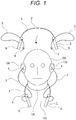
Fig. 1 shows an embodiment of a sound output device of the present technology together withFigs. 2 to 10 , and this view is an explanatory view showing a state before and after the sound output device is worn by a user. -
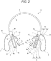
Fig. 2 is a front view of the sound output device. -
Fig. 3 is a front view showing a part of the sound output device. -
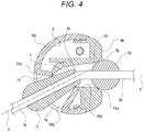
Fig. 4 is a cross-sectional view showing an insertion state of a cable with respect to an insertion hole. -
Fig. 5 is an explanatory view showing a state where the sound output device is worn by a user. -
Fig. 6 is a front view showing another example of the sound output device. -
Fig. 7 is a front view showing further another example of the sound output device. -
Fig. 8 is a front view showing yet another example of the sound output device. -
Fig. 9 is a front view showing still another example of the sound output device. -
Fig. 10 is a cross-sectional view showing another example of the insertion hole of the sound output device. - Hereinafter, an embodiment for implementing a sound output device of the present technology is described with reference to the accompanying drawings.
- An embodiment described below is an application of the sound output device of the present technology to an earphone. However, the application range of the present technology is not limited to earphones, and the present technology can be widely applied to various other sound output devices such as headphones.
- In the following description, front, back, upper, lower, left, and right directions are indicated in directions viewed from a user at a time of wearing the sound output device. Note that the front, back, upper, lower, right, and left directions shown below are for convenience of description, and implementation of the present technology is not limited to these directions.
- A
sound output device 1 includes aneck band 2 worn on aneck 101 of auser 100, acable 3 partially led out from theneck band 2, andearphones Figs. 1 and2 ). - In the
sound output device 1, theneck band 2 is worn on theneck 101 of theuser 100 from a back side of theuser 100. Theneck band 2 is formed in a U-shape opened downward, for example, in a state of being worn on theneck 101, and both end portions are apart from each other left and right and positioned near achest 102 of theuser 100. - The
neck band 2 has anintermediate unit 5 that is curved or at least partially bent, andarrangement units intermediate unit 5. A stable state of thesound output device 1 being worn by theuser 100 is maintained by thearrangement units neck band 2 being positioned lower than theneck 101 of theuser 100. - The
cable 3 is individually led out from thearrangement units neck band 2. In a state where thesound output device 1 is worn by theuser 100, theearphones cable 3 are individually worn in aleft ear 103 and aright ear 104 of the user. - In the
neck band 2, at least theintermediate unit 5 is formed by an elastically deformable material, and is curved so as to be elastically deformable in a direction in which thearrangement units intermediate unit 5, for example, a part of thecable 3 is disposed. - In a state where the
neck band 2 is worn on theneck 101 of theuser 100, a part of theintermediate unit 5 is positioned on a back side of theneck 101, and thearrangement units chest 102. - When the
neck band 2 is worn on theneck 101 of theuser 100, theintermediate unit 5 is elastically deformed such that thearrangement units intermediate unit 5 is elastically restored such that thearrangement units Fig. 1 ). This configuration facilitates theneck band 2 to be worn on theneck 101, and makes it difficult for theneck band 2 to come off from theneck 101 in the worn state, to secure a stable wearing state of thesound output device 1. - The
arrangement units arrangement unit 6 provided on the left side will be described as an example unless otherwise stated. - The
arrangement unit 6 is formed by, for example, a resin material so as to have a substantially cylindrical outer shape, and has a shape extending in a direction continuous with theintermediate unit 5. Thearrangement unit 6 includes, for example, afirst member 6a and asecond member 6b bound in a direction orthogonal to an axial direction thereof, and an internal space is formed as an arrangement space S. In the arrangement space S, an internal structure as described later is arranged. At a position closer to theintermediate unit 5 in thearrangement unit 6, aninsertion hole 7 through which thecable 3 is inserted is formed. Note that thearrangement unit 6 is not limited to the structure where thefirst member 6a and thesecond member 6b are bound, but may be entirely formed by bonding of one or three or more members. - The
arrangement unit 6 is formed to have a diameter larger than that of theintermediate unit 5. Since thecable 3 is inserted into thearrangement unit 6 having a diameter larger than that of theintermediate unit 4, thecable 3 can be easily drawn out, and a sufficient arrangement space between thecable 3 and the internal structure can be secured. - In a state where the
neck band 2 is worn on theneck 101 of theuser 100, as described above, thearrangement units arrangement units neck band 2 is an inner side. - Since various internal structures are arranged in the
arrangement units arrangement units intermediate unit 5. Therefore, the weight of both end portions of theneck band 2 increases, thearrangement units intermediate unit 5 in a state where theneck band 2 is worn on theneck 101 of theuser 100, and a stable wearing state of theneck band 2 can be secured. - Hereinafter, with the
arrangement unit 6 positioned on the left side of theuser 100 defined as anarrangement unit 6L and thearrangement unit 6 positioned on the right side defined as anarrangement unit 6R when theneck band 2 is worn, a configuration peculiar to thearrangement units - In the arrangement space S of the
arrangement unit 6L, for example, as an internal structure, acontrol board 8, a microphone (not shown), a vibration motor (not shown), and the like are arranged (seeFig. 2 ). - The
control board 8 is formed with a drive circuit that operates a speaker as described later, and anantenna 8a for wireless communication as a communication device. Therefore, thesound output device 1 can receive a sound signal from an external device such as a music player by wireless communication, and convert the received sound signal to output as sound from the speaker. As the wireless communication for receiving a sound signal, for example, Bluetooth (registered trademark) or wireless fidelity (Wi-Fi, registered trademark) is used. - The
antenna 8a as a communication device formed on thecontrol board 8 is positioned at an end portion opposite to theintermediate unit 5 in the arrangement space S. The communication sensitivity of theantenna 8a tends to be higher as being positioned farther from the body of theuser 100. Therefore, by arranging theantenna 8a at the end portion opposite to theintermediate unit 5 in the arrangement space S far from the body of theuser 100, a good communication state can be secured. - The microphone functions as a sound input device to which external sound is inputted. The microphone is connected to the
control board 8, and the inputted sound signal is transmitted to an external device via, for example, a communication device. To the microphone, sound is inputted through a sound input hole (not shown) formed in thearrangement unit 6. - The vibration motor is controlled by the
control board 8 and notifies theuser 100 of an operation state of thesound output device 1 by a predetermined vibration mode. The vibration motor notifies theuser 100 of reception of a call request from another call terminal, for example, by vibrating. - On an outer peripheral portion of the
arrangement unit 6L, a plurality ofoperation buttons control board 8 is provided. As theoperation buttons main operation button 9a, afirst adjustment button 9b, and asecond adjustment button 9c are provided apart in a longitudinal direction of thearrangement unit 6L. When themain operation button 9a is subjected to long depression, power to thesound output device 1 is turned on or off. When themain operation button 9a is subjected to short depression in the power-on state, sound is reproduced or stopped. Furthermore, it is possible to perform track forward, track reverse, fast reverse, execution of a pairing function with an external device, and the like by a predetermined operation of themain operation button 9a. When thefirst adjustment button 9b or thesecond adjustment button 9c is subjected to short depression in the power-on state, volume of the sound to be outputted is increased or decreased. Note that the function of eachoperation button 9 is not limited to the above, and oneoperation button 9 may be configured to realize a plurality of functions by a predetermined operation mode such as long depression or short depression. Furthermore, the configuration may be such that theoperation buttons - The
arrangement unit 6L is provided with alighting unit 10 connected to thecontrol board 8. As thelighting unit 10, for example, a light emitting diode (LED) is used. As thelighting unit 10, afirst lighting unit 10a indicating a charging state and asecond lighting unit 10b indicating an operation state of thesound output device 1 are provided. By visually recognizing a lighting state of thelighting unit 10, theuser 100 can easily check the operation state of thesound output device 1. - In the
arrangement unit 6L, aterminal unit 11 is provided. For example, a universal serial bus (USB) terminal is used as theterminal unit 11. Using theterminal unit 11 makes it possible to perform charging of a battery as described later, input/output of sound data, and the like. - In the arrangement space S of the
arrangement unit 6R, a short-distancewireless communication unit 12, abattery 13, and the like are arranged. - The short-distance
wireless communication unit 12 as a communication device is, for example, a near field communication (NFC) tag, and has a function of pairing processing and the like such as connection authentication. The short-distancewireless communication unit 12 is connected to thecontrol board 8 via a cable (not shown) disposed in theintermediate unit 5, and cooperates with thecontrol board 8 to realize wireless communication. - The short-distance
wireless communication unit 12 is held, for example, in a state of being affixed to the arrangement space S. - The
battery 13 is a chargeable type, for example, and is connected to theterminal unit 11 of thearrangement unit 6L via thecable 3 arranged in theintermediate unit 5. Thebattery 13 is supplied with electric power from outside via theterminal unit 11. Electric power of thebattery 13 is supplied to thecontrol board 8, the microphone, the vibration motor, thelighting unit 10, and the like described above. Note that thebattery 13 may be a disposable type, and in this case, it is desirable that a part of thearrangement unit 6R is openable and closable, and thebattery 13 is replaceable. Furthermore, even in a case where thebattery 13 is of a chargeable type, a part of thearrangement unit 6 may be openable and closable, and thebattery 13 may be replaceable. - The above has shown the configuration in which various internal structures are dispersed and arranged in the
arrangement unit 6L and thearrangement unit 6R. With this configuration, the weight of theneck band 2 can be easily dispersed evenly to the left and right, and a stable wearing state can be maintained in a state where theneck band 2 is worn on theneck 101. Note that the internal configuration of thearrangement unit 6 is not limited to the above. For example, the configuration may be such that all the internal structures are arranged in one of thearrangement unit 6L or thearrangement unit 6R. - Next, a schematic configuration of the
earphone 4 will be described with reference toFig. 2 . Theearphone 4 is a canal type earphone, for example, and includes: a speaker (not shown) that converts a sound signal into vibration to output as sound; acasing 4a in which the speaker is disposed; and anearpiece 4b attached to thecasing 4a. - Note that, although the canal type earphone has been shown as the
earphone 4 above, other types of earphones, such as inner-ear type, may be used, for example. - Hereinafter, a detailed configuration of the
arrangement unit 6 will be described with reference toFigs. 3 and4 . In thearrangement unit 6, a lead-out hole 14 whose one end is in communication with the arrangement space S is formed (seeFig. 3 ). An opening at another end of the lead-out hole 14 is formed as a lead-outopening 14a that opens to the outer side of theneck band 2. - The
insertion hole 7 is formed at a position closer to theintermediate unit 5 than the lead-outopening 14a. Theinsertion hole 7 penetrates thearrangement unit 6 substantially in the left-right direction. - The openings on both sides of the
insertion hole 7 are individually formed as afirst opening 7a and asecond opening 7b. Thefirst opening 7a is positioned on the inner side of theneck band 2, and thesecond opening 7b is positioned on the outer side. - The
insertion hole 7 includes afirst insertion part 15 continued to thefirst opening 7a, and asecond insertion part 16 continued to thesecond opening 7b (seeFig. 4 ). Thefirst insertion part 15 and thesecond insertion part 16 are in communication at an end portion opposite to thefirst opening 7a and an end portion opposite to thesecond opening 7b. In thefirst insertion part 15 and thesecond insertion part 16, a part of a stopper as described later can be individually inserted. - In the
insertion hole 7, thefirst insertion part 15 extends in a predetermined direction X, and thesecond insertion part 16 extends in a predetermined direction Y. The direction Y is inclined with respect to the direction X, and thesecond insertion part 16 is inclined with respect to thefirst insertion part 15. With this arrangement, orientation of thefirst opening 7a and thesecond opening 7b of theinsertion hole 7 is not limited to a single axial direction, and thecable 3 can be drawn out from theinsertion hole 7 in a desired direction by individually forming thefirst opening 7a and thesecond opening 7b toward a desired direction (any direction). - The
first insertion part 15 has aguide part 15a continued to thefirst opening 7a, and acommunication part 15b continued to theguide part 15a. - The
guide part 15a is formed at an end portion of thefirst insertion part 15 on thefirst opening 7a side, and is formed to have a smaller diameter as going inward theneck band 2. Thecommunication part 15b is formed to have a smaller diameter as going inward theneck band 2, and is formed, for example, in a mortar shape in a cross-sectional shape. An axial length of thecommunication part 15b is longer than an axial length of theguide part 15a. - The
second insertion part 16 has aguide part 16a continued to thesecond opening 7b, and acommunication part 16b continued to theguide part 16a. - The
guide part 16a is formed at an end portion of thesecond insertion part 16 on thesecond opening 7b side, and is formed to have a smaller diameter as going inward theneck band 2. Thecommunication part 16b is formed to have a smaller diameter as going inward of theneck band 2, and is in communication with thecommunication part 15b of thefirst insertion part 15. - Note that, although the example has been shown above in which the
first insertion part 15 and thesecond insertion part 16 are formed in different shapes, thesecond insertion part 16 may be formed in the same shape as thefirst insertion part 15. Furthermore, although the example has been shown above in which thesecond insertion part 16 is inclined with respect to thefirst insertion part 15, theinsertion hole 7 may be formed with thefirst insertion part 15 and thesecond insertion part 16 being in a straight line. Furthermore, thefirst insertion part 15 and thesecond insertion part 16 are not limited to the shape described above, but may have, for example, a shape in which theguide part 15a and theguide part 16a are not formed. - Hereinafter, with reference to
Figs. 3 to 5 , a drawn-out state of thecable 3 from thearrangement unit 6 is described. Thecable 3 is led out to the outer side of theneck band 2 from the lead-outopening 14a (seeFig. 3 ). In thecable 3, a portion positioned in the lead-outopening 14a is defined as the lead-out startingend 3a. - The
cable 3 led out to the outside of theneck band 2 is inserted into theinsertion hole 7, and can be drawn out on both sides of theinsertion hole 7. In thecable 3, a portion positioned in theinsertion hole 7, in other words, a portion from thefirst opening 7a to thesecond opening 7b is defined as the insertedportion 3b (seeFig. 4 ) . - When a portion from the one end portion connected with the
earphone 4 in thecable 3 to connecting to the insertedportion 3b is defined as afirst portion 3c, thefirst portion 3c is a portion drawn out from thefirst opening 7a of theinsertion hole 7 to the inner side of the neck band 2 (seeFig. 3 ). In other words, in a state where thesound output device 1 is worn by theuser 100, thefirst portion 3c is positioned on theneck 101 side of the user 100 (seeFig. 5 ). - When a portion from the lead-out starting
end 3a of thecable 3 to connecting to the insertedportion 3b is defined as asecond portion 3d, thesecond portion 3d is a portion drawn out from thesecond opening 7b of theinsertion hole 7 to the outer side of the neck band 2 (seeFig. 3 ). In a state where thesound output device 1 is worn by theuser 100, thesecond portion 3d is positioned outward from theneck 101 of the user 100 (seeFig. 5 ). - In the
cable 3, a length from the lead-out startingend 3a to one end portion connected with theearphone 4 is made constant. Therefore, in a case where thecable 3 is drawn out from theinsertion hole 7 as thefirst portion 3c, the length of thesecond portion 3d is shortened. Conversely, in a case where thecable 3 is drawn out from theinsertion hole 7 as thesecond portion 3d, the length of thefirst portion 3c is shortened. - Note that, in
Fig. 4 and the like, although an example has been shown in which a surface of thecable 3 is formed in a curved shape, a plurality of uneven portions extending in an axial direction and arranged in a circumferential direction of thecable 3 may be formed on the surface of thecable 3. This configuration can reduce touch noise even in a case where a hand of theuser 100 touches thecable 3. - Next, with reference to
Fig. 5 , a description is given to a drawn-out state of thecable 3 from thearrangement unit 6 in a state where thesound output device 1 is worn by theuser 100. -
Fig. 5A shows a state where theearphones user 100 when thesound output device 1 is used. At this time, thefirst portion 3c of thecable 3 is made longer than thesecond portion 3d. - Whereas, in a state where the
earphone 4 is removed from the ear, in a case where thefirst portion 3c is made to have the same length as that when theearphone 4 is worn, usability may be deteriorated such as when thefirst portion 3c hangs down due to the weight of theearphone 4 and comes into contact with a hand or the like of theuser 100. Therefore, it is desirable to increase the length of thesecond portion 3d and shorten the length of thefirst portion 3c by drawing out thecable 3 from theinsertion hole 7 and changing the position of the insertedportion 3b of the cable 3 (seeFig. 5B ). - Thus, by adjusting the drawn-out state of the
cable 3 so as to make thefirst portion 3c of thecable 3 shorter than thesecond portion 3d, thefirst portion 3c does not interfere with theuser 100. - In a case of wearing the
earphones earphones Fig. 5B , it is desirable to increase the length of thefirst portion 3c by drawing out thecable 3 toward the inner side from theinsertion hole 7 to change the position of the insertedportion 3b of the cable 3 (seeFig. 5A ). - With the above configuration, by changing the position of the inserted
portion 3b of thecable 3, the lengths of thefirst portion 3c and thesecond portion 3d positioned on both sides of theinsertion hole 7 are changed in accordance with a usage state of thesound output device 1. - Hereinafter, configurations of a
first stopper 17 and asecond stopper 18 supported by thecable 3 will be described with reference toFigs. 3 to 5 . - In the
cable 3, thefirst stopper 17 and thesecond stopper 18 are each slidably supported on both sides with the insertedportion 3b interposed in between (seeFig. 3 ). In thecable 3, thefirst stopper 17 is supported at a portion between the end portion connected to theearphone 4 and the insertedportion 3b, and thesecond stopper 18 is supported at a portion between the lead-outposition 3a and the insertedportion 3b. - The
first stopper 17 and thesecond stopper 18 are formed by, for example, a resin material such as polyvinyl chloride (PVC), and have a through hole (not shown) through which thecable 3 penetrates. - Since the
first stopper 17 and thesecond stopper 18 are slid with respect to thecable 3 by applying a certain force of a certain level or more in an axial direction of the through hole, thefirst stopper 17 and thesecond stopper 18 can be moved to a desired position on thecable 3. In a state where a force of a certain level or more is not applied, thefirst stopper 17 and thesecond stopper 18 are held at a predetermined position of thecable 3, and moved along with thecable 3. - The
first stopper 17 is formed such that a diameter decreases as approaching the lead-out startingend 3a. Thefirst stopper 17 is formed to have an outer shape of, for example, a substantially truncated cone shape. An outer peripheral surface of thefirst stopper 17 is formed in a curved surface shape, and when thefirst stopper 17 is moved along with thecable 3, thefirst stopper 17 is unlikely to be caught by clothes or the like of theuser 100. - When the
cable 3 is drawn out in a direction in which thesecond portion 3d becomes long, thefirst stopper 17 is moved toward theinsertion hole 7 along with thecable 3, and is partially inserted into the first insertion part 15 (seeFigure 4 ). A part of thefirst stopper 17 is guided by a wall surface forming theguide part 15a and inserted into thefirst insertion part 15, and a part is held in a state of being in contact with a part of the wall surface forming thecommunication part 15b, or with a boundary portion between thecommunication part 15b and thecommunication part 16b. At this time, movement of thefirst stopper 17 is restricted by a side pressure from a wall surface forming theinsertion hole 7, and movement of thecable 3 with respect to theneck band 2 is restricted. - With the above configuration, by holding the
first stopper 17 at a desired position of thecable 3, it is possible to prevent excessive drawing of thecable 3 in the direction in which thesecond portion 3d becomes long. Therefore, thesecond portion 3d is prevented from being excessively long, and thecable 3 is not easily touched unintentionally by a hand or the like of theuser 100 that is often positioned outward of thearrangement unit 6. - The
second stopper 18 is formed to have an outer shape of, for example, a substantially spherical shape. - When the
cable 3 is drawn out in a direction in which thefirst portion 3c becomes long, thesecond stopper 18 is moved toward theinsertion hole 7 along with thecable 3, and is partially inserted into the second insertion part 16 (seeFigure 4 ). A part of thesecond stopper 18 is guided by a wall surface forming theguide part 16a and inserted into thesecond insertion part 16, and is contacted with a part of the wall surface forming theguide part 16a or with a boundary portion between theguide part 16a and thecommunication part 16b. At this time, movement of thecable 3 with respect to theneck band 2 is restricted. - With the above configuration, by holding the
second stopper 18 at a predetermined position of thesecond portion 3d, it is possible to prevent excessive drawing of thecable 3 in the direction in which thefirst portion 3c becomes long. Therefore, thefirst portion 3c is prevented from being excessively long, and the hanging of thefirst portion 3c is suppressed. - In the configuration described above, the
first stopper 17 and thesecond stopper 18 are held on both sides with the insertedportion 3b interposed in between. Therefore, when thecable 3 is drawn out to each of both sides of theinsertion hole 7, thefirst stopper 17 or thesecond stopper 18 restricts movement of thecable 3 with respect to theneck band 2, and excessive drawing of thecable 3 can be prevented on both sides of theinsertion hole 7. Moreover, the insertedportion 3b is fixed at a desired position by reliably restricting the movement of thecable 3 from both sides of theinsertion hole 7, and each of thefirst portion 3c and thesecond portion 3d can be kept at a desired length (seeFig. 4 ). By keeping thefirst portion 3c at a desired length, unintentional removal of theearphone 4 from the ear due to change in the length of thefirst portion 3c can be prevented. Furthermore, by keeping thesecond portion 3d at a desired length, thesecond portion 3d having a desired length or more is not positioned outward of theneck band 2, and is less likely to interfere with theuser 100. - In the configuration described above, at least a part of each of the
first stopper 17 and thesecond stopper 18 can be inserted into theinsertion hole 7. Therefore, since thefirst stopper 17 and thesecond stopper 18 are not entirely positioned outside theneck band 2, theuser 100 is less likely to be disturbed. - Furthermore, in the configuration described above, the
first stopper 17 and thesecond stopper 18 are formed in different shapes. Therefore, the tactile senses of thefirst stopper 17 and thesecond stopper 18 are different, and theuser 100 can easily distinguish thefirst stopper 17 and thesecond stopper 18 by touching with a hand. - Note that the shape of the
second stopper 18 is not limited to the shape described above. For example, thesecond stopper 18 may be formed to have an outer shape of a substantially truncated cone shape. In this case, movement of thecable 3 can be reliably restricted on both sides of theinsertion hole 7. - Note that the shape of the
first stopper 17 is also not limited to the shape described above. For example, thefirst stopper 17 may be formed to have an outer diameter of a substantially spherical shape. Furthermore, the shapes of thefirst stopper 17 and thesecond stopper 18 are not limited to the outer shapes of the substantially truncated cone shape and the substantially spherical shape, but may be formed into any shape. - As described above, in the
sound output device 1, thecable 3 can be drawn out from theneck band 2 to both sides of theinsertion hole 7, and a length of a portion on both sides of theinsertion hole 7 in thecable 3 is changed by changing a position of the insertedportion 3b of thecable 3 in theinsertion hole 7. - With this configuration, since a length of each portion of the
first portion 3c and thesecond portion 3d positioned on both sides of theinsertion hole 7 is changed by changing the position of the insertedportion 3b of thecable 3, it is possible to improve usability while securing functionality of thesound output device 1. - Furthermore, in the
sound output device 1 described above, thefirst opening 7a of theinsertion hole 7 is positioned on the inner side, and thesecond opening 7b is positioned on the outer side. - With this arrangement, the
first portion 3c drawn out from thefirst opening 7a of theinsertion hole 7 is positioned on the inner side of the neck band 2 (theneck 101 side of the user 100), and thesecond portion 3d drawn out from thesecond opening 7b is positioned on the outer side of the neck band 2 (outward from theneck 101 of the user 100). Since a hand of theuser 100 is often positioned outward of thearrangement unit 6 in a state where theneck band 2 is worn on theneck 101, thesecond portion 3d positioned on the outer side of theneck band 2 is easily drawn out by theuser 100. - Furthermore, in the
sound output device 1 described above, theinsertion hole 7 is positioned closer to theintermediate unit 5 than the lead-outopening 14a. - Therefore, the
first portion 3c of thecable 3 is drawn out from thefirst opening 7a of theinsertion hole 7 positioned closer to theintermediate unit 5 than the lead-outopening 14a. Since a distance from theinsertion hole 7 to the ear of theuser 100 is short, the length of thefirst portion 3c of thecable 3 drawn out from the first opening 7c of theinsertion hole 7 is shortened when theearphone 4 is worn, and hanging of thefirst portion 3c can be suppressed. - Hereinafter, with reference to
Figs. 6 to 10 , another configuration example of the sound output device of the present technology is described. - In a
sound output device 1A of a first configuration example, the lead-outopening 14a is positioned closer to theintermediate unit 5 than the insertion hole 7 (seeFig. 6 ). - In the
sound output device 1A, thecable 3 is led out from the lead-outopening 14a to the outer side of theneck band 2, and inserted into theinsertion hole 7. At this time, thesecond portion 3d is positioned closer to theintermediate unit 5 than thefirst portion 3c. In this case, in a state where theearphone 4 is not worn in the ear when theneck band 2 is worn, thefirst portion 3c is at a position farther from theneck 101 than thesecond portion 3d. Therefore, thefirst portion 3c is less likely to be in contact with theneck 101 or the like, and is less likely to interfere with theuser 100. Moreover, since thefirst portion 3c is at a position closer to a hand of theuser 100 than thesecond portion 3d in the up-down direction in a state where theearphone 4 is not worn in the ear, theuser 100 can easily wear theearphone 4 by picking up theearphone 4 connected to thefirst portion 3c or a tip end thereof. - In a
sound output device 1B of a second configuration example, the lead-outopening 14a is positioned on the inner side of the neck band 2 (seeFig. 7 ) . - In the
arrangement unit 6, theinsertion hole 7 is positioned closer to theintermediate unit 5 than the lead-outopening 14a. At least a part of theinsertion hole 7 is curved or bent, and thefirst opening 7a and thesecond opening 7b are each positioned on the inner side of theneck band 2. - In the
sound output device 1B described above, thecable 3 is led out from the lead-outopening 14a to the inner side of theneck band 2, and inserted into theinsertion hole 7. Since thefirst opening 7a and thesecond opening 7b are positioned on the inner side of theneck band 2, thefirst portion 3c and thesecond portion 3d respectively drawn out from thefirst opening 7a and thesecond opening 7b are positioned on the inner side of theneck band 2. Therefore, since thefirst portion 3c and thesecond portion 3d are not positioned on the outer side of theneck band 2, a hand theuser 100 positioned on the outer side of theneck band 2 is less likely to contact thecable 3 unintentionally. - In a sound output device 1C of a third configuration example, the lead-out
opening 14a is positioned on the inner side of the neck band 2 (seeFig. 8 ) . - The lead-out
opening 14a is positioned closer to theintermediate unit 5 than theinsertion hole 7. - For example, at least a part of the
insertion hole 7 is curved or bent, and thefirst opening 7a and thesecond opening 7b are each positioned on the inner side of theneck band 2. Thesecond opening 7b is positioned closer to theintermediate unit 5 than thefirst opening 7a. - In the sound output device 1C described above, the
cable 3 is led out from the lead-outopening 14a to the inner side of theneck band 2, and inserted into theinsertion hole 7. At this time, thesecond portion 3d is positioned closer to theintermediate unit 5 than thefirst portion 3c. In this case, in a state where theearphone 4 is not worn in the ear when theneck band 2 is worn, thefirst portion 3c is at a position farther from theneck 101 than thesecond portion 3d. Therefore, thefirst portion 3c is less likely to be in contact with theneck 101 or the like, and is less likely to interfere with theuser 100. Moreover, since thefirst portion 3c is at a position closer to a hand of theuser 100 than thesecond portion 3d in the up-down direction in a state where theearphone 4 is not worn in the ear, theuser 100 can easily wear theearphone 4 by picking up theearphone 4 connected to thefirst portion 3c or a tip end thereof. - Moreover, in the sound output device 1C described above, the
cable 3 is led out from the lead-outopening 14a to the inner side of theneck band 2, and inserted into theinsertion hole 7. Since thefirst opening 7a and thesecond opening 7b are positioned on the inner side of theneck band 2, thefirst portion 3c and thesecond portion 3d of thecable 3 respectively drawn out from thefirst opening 7a and thesecond opening 7b are positioned on the inner side (theneck 101 side of the user 100) of theneck band 2. Therefore, since thefirst portion 3c and thesecond portion 3d are not positioned on the outer side of theneck band 2, a hand theuser 100 positioned on the outer side of theneck band 2 is less likely to contact thecable 3 unintentionally. - Note that, in the above, an example has been shown in which the
first opening 7a is positioned on the inner side of theneck band 2, and thesecond opening 7b and the lead-outopening 14a are individually on the inner side or the outer side of theneck band 2. However, thefirst opening 7a, thesecond opening 7b, and the lead-outopening 14a may be individually formed at any positions on thearrangement unit 6. - For example, the
first opening 7a may be positioned on the outer side of the neck band 2 (seeFig. 9 ). In this case, since thefirst portion 3c is positioned on the outer side of theneck band 2 that is easily accessible by a hand of theuser 100, thefirst portion 3a can be easily drawn out. Furthermore, in addition to thefirst opening 7a, thesecond opening 7b and the lead-outopening 14a may be individually positioned on the outer side of theneck band 2. In this case, since thesecond portion 3d is positioned on the outer side of theneck band 2 together with thefirst portion 3c, thesecond portion 3d can be easily drawn out in addition to thefirst portion 3c. - Note that, in the above, an example has been shown in which the
first opening 7a, thesecond opening 7b, and the lead-outopening 14a are opened on the inner side or the outer side of theneck band 2. However, thefirst opening 7a, thesecond opening 7b, the lead-outopening 14a, and theinsertion hole 7 may be opened at any position on an outer peripheral surface or a tip end surface of thearrangement unit 6. - Note that, in the above, an example has been shown in which the
insertion hole 7 penetrating theneck band 2 is formed in thearrangement unit 6, and the openings on both sides of theinsertion hole 7 are individually made as thefirst opening 7a and thesecond opening 7b. However, a shape of theinsertion hole 7 is not limited to the above example. For example, twoinsertion holes arrangement unit 6 with the outside may be formed, and the outward openings in the insertion holes 7 and 7 each may be formed as thefirst opening 7a and thesecond opening 7b (seeFig. 10 ). - Although an example has been shown in which the
insertion hole 7 is formed in thearrangement unit 6 in the above, theinsertion hole 7 may be formed at any other position of theneck band 2, such as a part of theintermediate unit 5, for example. - Note that the effects described in this specification are merely examples and are not limited, and other effects may be present.
- The present technology can have the following configurations.
- (1) A sound output device including:
- a neck band to be worn on a user's neck and having an insertion hole;
- a cable partially led out from the neck band; and
- an earphone connected to the cable, in which
- the cable can be drawn out from the neck band to both sides of the insertion hole, and
- a length of a portion on both sides of the insertion hole in the cable is changed by changing a position of an inserted portion of the cable in the insertion hole.
- (2) The sound output device according to (1) above, in which
the neck band has an intermediate unit that is curved or at least partially bent, and an arrangement unit individually continued to both ends of the intermediate unit and arranged with an internal structure. - (3) The sound output device according to (2) above, in which
a diameter of the arrangement unit is made larger than a diameter of the intermediate unit, and
the insertion hole is formed in the arrangement unit. - (4) The sound output device according to (2) above or (3) above, in which
the insertion hole has a first portion extending in a predetermined direction and a second portion inclined with respect to the first portion. - (5) The sound output device according to any one of (2) above to (4) above, in which
two of the arrangement units are positioned apart from each other substantially left and right in a state where the neck band is worn on the user's neck, and
when a side where both are facing in two of the arrangement units is an inner side,
one opening of the insertion hole is positioned on the inner side, and
another opening of the insertion hole is positioned on an outer side. - (6) The sound output device according to any one of (2) above to (4) above, in which
two of the arrangement units are positioned apart from each other substantially left and right in a state where the neck band is worn on the user's neck, and
when a side where both are facing in two of the arrangement units is an inner side,
one opening and another opening of the insertion hole are positioned on the inner side. - (7) The sound output device according to any one of (2) above to (6) above, in which
a lead-out opening through which the cable is led out is formed in the arrangement unit, and
the insertion hole is positioned closer to the intermediate unit than the lead-out opening. - (8) The sound output device according to any one of (2) above to (6) above, in which
a lead-out opening through which the cable is led out is formed in the arrangement unit, and
the lead-out opening is positioned closer to the intermediate unit than the insertion hole. - (9) The sound output device according to any one of (2) above to (8) above, in which
the cable supports a stopper configured to restrict movement of the cable with respect to the neck band. - (10) The sound output device according to (9) above, in which
the stopper is supported slidably by the cable. - (11) The sound output device according to (9) above or (10) above, in which
at least a part of the stopper can be inserted into the insertion hole. - (12) The sound output device according to (11) above, in which
a diameter of at least a part of the insertion hole decreases as going inward in the neck band. - (13) The sound output device according to any one of (9) above to (12) above, in which
when an end portion connected with the earphone in the cable is defined as one end portion,
the stopper is positioned between the one end portion of the cable and the inserted portion. - (14) The sound output device according to (13), in which
the stopper is formed to have an outer shape of a substantially truncated cone shape. - (15) The sound output device according to any one of (9) above to (12) above, in which
a lead-out opening through which the cable is led out is formed in the arrangement unit, and
when a portion positioned in the lead-out opening in the cable is defined as a lead-out starting end,
the stopper is positioned between the lead-out starting end and the inserted portion in the cable. - (16) The sound output device according to any one of (9) above to (12) above, in which
two of the stoppers are provided and positioned on opposite sides with the inserted portion interposed in between. - (17) The sound output device according to (16) above, in which
the two stoppers are each formed in different shapes. - (18) The sound output device according to any one of (2) above to (17) above, in which
a communication device is provided as the internal structure, and
the communication device is disposed at a tip end portion of the arrangement unit. -
- 1
- Sound output device
- 2
- Neck band
- 3
- Cable
- 3a
- Lead-out starting end
- 3b
- Inserted portion
- 3c
- First portion
- 3d
- Second portion
- 4
- Earphone
- 5
- Intermediate unit
- 6
- arrangement unit
- 7
- Insertion hole
- 7a
- First opening
- 7b
- Second opening
- 14a
- Lead-out opening
- 15
- First insertion part
- 16
- Second insertion part
- 17
- First stopper
- 18
- Second stopper
- 1A
- Sound output device
- 1B
- Sound output device
- 1C
- Sound output device
Claims (18)
- A sound output device comprising:a neck band to be worn on a user's neck and having an insertion hole;a cable partially led out from the neck band; andan earphone connected to the cable, whereinthe cable can be drawn out from the neck band to both sides of the insertion hole, anda length of a portion on both sides of the insertion hole in the cable is changed by changing a position of an inserted portion of the cable in the insertion hole.
- The sound output device according to claim 1, wherein
the neck band has an intermediate unit that is curved or at least partially bent, and an arrangement unit individually continued to both ends of the intermediate unit and arranged with an internal structure. - The sound output device according to claim 2, wherein
a diameter of the arrangement unit is made larger than a diameter of the intermediate unit, and
the insertion hole is formed in the arrangement unit. - The sound output device according to claim 2, wherein
the insertion hole has a first portion extending in a predetermined direction and a second portion inclined with respect to the first portion. - The sound output device according to claim 2, wherein
two of the arrangement units are positioned apart from each other substantially left and right in a state where the neck band is worn on the user's neck, and
when a side where both are facing in two of the arrangement units is an inner side,
one opening of the insertion hole is positioned on the inner side, and
another opening of the insertion hole is positioned on an outer side. - The sound output device according to claim 2, wherein
two of the arrangement units are positioned apart from each other substantially left and right in a state where the neck band is worn on the user's neck, and
when a side where both are facing in two of the arrangement units is an inner side,
one opening and another opening of the insertion hole are positioned on the inner side. - The sound output device according to claim 2, wherein
a lead-out opening through which the cable is led out is formed in the arrangement unit, and
the insertion hole is positioned closer to the intermediate unit than the lead-out opening. - The sound output device according to claim 2, wherein
a lead-out opening through which the cable is led out is formed in the arrangement unit, and
the lead-out opening is positioned closer to the intermediate unit than the insertion hole. - The sound output device according to claim 2, wherein
the cable supports a stopper configured to restrict movement of the cable with respect to the neck band. - The sound output device according to claim 9, wherein
the stopper is supported slidably by the cable. - The sound output device according to claim 9, wherein
at least a part of the stopper can be inserted into the insertion hole. - The sound output device according to claim 11, wherein
a diameter of at least a part of the insertion hole decreases as going inward in the neck band. - The sound output device according to claim 9, wherein
when an end portion connected with the earphone in the cable is defined as one end portion,
the stopper is positioned between the one end portion of the cable and the inserted portion. - The sound output device according to claim 13, wherein
the stopper is formed to have an outer shape of a substantially truncated cone shape. - The sound output device according to claim 9, wherein
a lead-out opening through which the cable is led out is formed in the arrangement unit, and
when a portion positioned in the lead-out opening in the cable is defined as a lead-out starting end,
the stopper is positioned between the lead-out starting end and the inserted portion in the cable. - The sound output device according to claim 9, wherein
two of the stoppers are provided and positioned on opposite sides with the inserted portion interposed in between. - The sound output device according to claim 16, wherein
the two stoppers are each formed in different shapes. - The sound output device according to claim 2, wherein
a communication device is provided as the internal structure, and
the communication device is disposed at a tip end portion of the arrangement unit.
Applications Claiming Priority (3)
| Application Number | Priority Date | Filing Date | Title |
|---|---|---|---|
| JP2017115965 | 2017-06-13 | ||
| JP2017139198 | 2017-07-18 | ||
| PCT/JP2018/017775 WO2018230192A1 (en) | 2017-06-13 | 2018-05-08 | Sound output device |
Publications (2)
| Publication Number | Publication Date |
|---|---|
| EP3641332A1 true EP3641332A1 (en) | 2020-04-22 |
| EP3641332A4 EP3641332A4 (en) | 2020-06-10 |
Family
ID=64660407
Family Applications (1)
| Application Number | Title | Priority Date | Filing Date |
|---|---|---|---|
| EP18818776.9A Withdrawn EP3641332A4 (en) | 2017-06-13 | 2018-05-08 | SOUND OUTPUT DEVICE |
Country Status (5)
| Country | Link |
|---|---|
| US (1) | US11146875B2 (en) |
| EP (1) | EP3641332A4 (en) |
| JP (1) | JP7196840B2 (en) |
| CN (1) | CN110710227B (en) |
| WO (1) | WO2018230192A1 (en) |
Families Citing this family (1)
| Publication number | Priority date | Publication date | Assignee | Title |
|---|---|---|---|---|
| TW202224398A (en) | 2020-10-26 | 2022-06-16 | 美商米德蘭無線電公司 | Ear-mounted two-way radio system |
Family Cites Families (7)
| Publication number | Priority date | Publication date | Assignee | Title |
|---|---|---|---|---|
| JP3819740B2 (en) * | 2001-07-17 | 2006-09-13 | 三洋電機株式会社 | Neck-mounted audio player |
| JP2009027621A (en) * | 2007-07-23 | 2009-02-05 | Victor Co Of Japan Ltd | Headphone |
| KR101278246B1 (en) * | 2012-12-18 | 2013-06-24 | 방춘희 | Line adjusting apparatus |
| US20140205108A1 (en) * | 2013-01-21 | 2014-07-24 | Patrick R. Triato | Necklace-Style Wireless Audio Headset |
| JP3185367U (en) * | 2013-05-20 | 2013-08-15 | 株式会社ベリカ | Neck earphone storage container |
| EP2919482B1 (en) * | 2014-03-13 | 2019-11-06 | LG Electronics Inc. | Wireless ear piece |
| EP3007029B1 (en) | 2014-10-07 | 2017-12-27 | LG Electronics Inc. | Mobile terminal and wearable device |
-
2018
- 2018-05-08 WO PCT/JP2018/017775 patent/WO2018230192A1/en not_active Ceased
- 2018-05-08 EP EP18818776.9A patent/EP3641332A4/en not_active Withdrawn
- 2018-05-08 US US16/619,127 patent/US11146875B2/en active Active
- 2018-05-08 JP JP2019525198A patent/JP7196840B2/en active Active
- 2018-05-08 CN CN201880037610.5A patent/CN110710227B/en active Active
Also Published As
| Publication number | Publication date |
|---|---|
| CN110710227A (en) | 2020-01-17 |
| US20200120410A1 (en) | 2020-04-16 |
| US11146875B2 (en) | 2021-10-12 |
| WO2018230192A1 (en) | 2018-12-20 |
| JP7196840B2 (en) | 2022-12-27 |
| CN110710227B (en) | 2021-11-12 |
| EP3641332A4 (en) | 2020-06-10 |
| JPWO2018230192A1 (en) | 2020-04-16 |
Similar Documents
| Publication | Publication Date | Title |
|---|---|---|
| CN108184184B (en) | bluetooth earphone | |
| KR101006207B1 (en) | Headset with noise blocking means | |
| US8908899B1 (en) | Earphone | |
| KR102776026B1 (en) | Cradles and portable audio devices | |
| US10057397B2 (en) | Wireless headset and method of controlling the same | |
| US20060126882A1 (en) | Earphone | |
| KR200489806Y1 (en) | Output device of audio signal with bluetooth earphone and speaker | |
| CN1937438A (en) | Multi-functional bluetooth headset | |
| KR20190115962A (en) | Portable sound equipment system | |
| US20250294279A1 (en) | Sound output device | |
| WO2020152907A1 (en) | Earphone device | |
| JP2016072978A (en) | Non-contact rechargeable audio headset | |
| EP2680550B1 (en) | Hands-free communication devices for corded and wireless communication | |
| KR101218107B1 (en) | A bluetooth headset assembly | |
| US20140079240A1 (en) | Bluetooth headset | |
| KR101713808B1 (en) | Bluetooth Headset | |
| US11146875B2 (en) | Sound output device | |
| KR101142906B1 (en) | A earphone having signal input function of touchscreen | |
| KR102163066B1 (en) | ear tip and ear phone having the same | |
| US20250175751A1 (en) | Volume control system and volume control method | |
| KR20080073074A (en) | headset | |
| CN107547965A (en) | A kind of bluetooth earphone and terminal device | |
| KR20230052521A (en) | Wireless earbud charge cradle in which the vibration function is included | |
| KR200427268Y1 (en) | Ear microphone connection cable for wireless terminal | |
| JP2016051950A (en) | Cable unit and headphone |
Legal Events
| Date | Code | Title | Description |
|---|---|---|---|
| STAA | Information on the status of an ep patent application or granted ep patent |
Free format text: STATUS: THE INTERNATIONAL PUBLICATION HAS BEEN MADE |
|
| PUAI | Public reference made under article 153(3) epc to a published international application that has entered the european phase |
Free format text: ORIGINAL CODE: 0009012 |
|
| STAA | Information on the status of an ep patent application or granted ep patent |
Free format text: STATUS: REQUEST FOR EXAMINATION WAS MADE |
|
| 17P | Request for examination filed |
Effective date: 20200113 |
|
| AK | Designated contracting states |
Kind code of ref document: A1 Designated state(s): AL AT BE BG CH CY CZ DE DK EE ES FI FR GB GR HR HU IE IS IT LI LT LU LV MC MK MT NL NO PL PT RO RS SE SI SK SM TR |
|
| AX | Request for extension of the european patent |
Extension state: BA ME |
|
| A4 | Supplementary search report drawn up and despatched |
Effective date: 20200513 |
|
| RIC1 | Information provided on ipc code assigned before grant |
Ipc: H04R 5/033 20060101ALI20200507BHEP Ipc: H04R 1/10 20060101AFI20200507BHEP |
|
| DAV | Request for validation of the european patent (deleted) | ||
| DAX | Request for extension of the european patent (deleted) | ||
| STAA | Information on the status of an ep patent application or granted ep patent |
Free format text: STATUS: EXAMINATION IS IN PROGRESS |
|
| RAP3 | Party data changed (applicant data changed or rights of an application transferred) |
Owner name: SONY GROUP CORPORATION |
|
| 17Q | First examination report despatched |
Effective date: 20210630 |
|
| STAA | Information on the status of an ep patent application or granted ep patent |
Free format text: STATUS: THE APPLICATION HAS BEEN WITHDRAWN |
|
| 18W | Application withdrawn |
Effective date: 20221028 |