EP3641295A1 - Shooting interface switching method and apparatus, and device and storage medium thereof - Google Patents
Shooting interface switching method and apparatus, and device and storage medium thereof Download PDFInfo
- Publication number
- EP3641295A1 EP3641295A1 EP19204103.6A EP19204103A EP3641295A1 EP 3641295 A1 EP3641295 A1 EP 3641295A1 EP 19204103 A EP19204103 A EP 19204103A EP 3641295 A1 EP3641295 A1 EP 3641295A1
- Authority
- EP
- European Patent Office
- Prior art keywords
- user interface
- interface
- switching button
- shooting
- slide
- Prior art date
- Legal status (The legal status is an assumption and is not a legal conclusion. Google has not performed a legal analysis and makes no representation as to the accuracy of the status listed.)
- Granted
Links
Images



Classifications
-
- H—ELECTRICITY
- H04—ELECTRIC COMMUNICATION TECHNIQUE
- H04M—TELEPHONIC COMMUNICATION
- H04M1/00—Substation equipment, e.g. for use by subscribers
- H04M1/02—Constructional features of telephone sets
- H04M1/0202—Portable telephone sets, e.g. cordless phones, mobile phones or bar type handsets
- H04M1/0206—Portable telephones comprising a plurality of mechanically joined movable body parts, e.g. hinged housings
- H04M1/0208—Portable telephones comprising a plurality of mechanically joined movable body parts, e.g. hinged housings characterized by the relative motions of the body parts
- H04M1/0235—Slidable or telescopic telephones, i.e. with a relative translation movement of the body parts; Telephones using a combination of translation and other relative motions of the body parts
-
- H—ELECTRICITY
- H04—ELECTRIC COMMUNICATION TECHNIQUE
- H04M—TELEPHONIC COMMUNICATION
- H04M1/00—Substation equipment, e.g. for use by subscribers
- H04M1/72—Mobile telephones; Cordless telephones, i.e. devices for establishing wireless links to base stations without route selection
- H04M1/724—User interfaces specially adapted for cordless or mobile telephones
- H04M1/72403—User interfaces specially adapted for cordless or mobile telephones with means for local support of applications that increase the functionality
- H04M1/72406—User interfaces specially adapted for cordless or mobile telephones with means for local support of applications that increase the functionality by software upgrading or downloading
-
- H—ELECTRICITY
- H04—ELECTRIC COMMUNICATION TECHNIQUE
- H04N—PICTORIAL COMMUNICATION, e.g. TELEVISION
- H04N23/00—Cameras or camera modules comprising electronic image sensors; Control thereof
- H04N23/50—Constructional details
- H04N23/55—Optical parts specially adapted for electronic image sensors; Mounting thereof
-
- G—PHYSICS
- G06—COMPUTING OR CALCULATING; COUNTING
- G06F—ELECTRIC DIGITAL DATA PROCESSING
- G06F1/00—Details not covered by groups G06F3/00 - G06F13/00 and G06F21/00
- G06F1/16—Constructional details or arrangements
- G06F1/1613—Constructional details or arrangements for portable computers
- G06F1/1615—Constructional details or arrangements for portable computers with several enclosures having relative motions, each enclosure supporting at least one I/O or computing function
- G06F1/1624—Constructional details or arrangements for portable computers with several enclosures having relative motions, each enclosure supporting at least one I/O or computing function with sliding enclosures, e.g. sliding keyboard or display
-
- G—PHYSICS
- G06—COMPUTING OR CALCULATING; COUNTING
- G06F—ELECTRIC DIGITAL DATA PROCESSING
- G06F1/00—Details not covered by groups G06F3/00 - G06F13/00 and G06F21/00
- G06F1/16—Constructional details or arrangements
- G06F1/1613—Constructional details or arrangements for portable computers
- G06F1/1633—Constructional details or arrangements of portable computers not specific to the type of enclosures covered by groups G06F1/1615 - G06F1/1626
- G06F1/1684—Constructional details or arrangements related to integrated I/O peripherals not covered by groups G06F1/1635 - G06F1/1675
- G06F1/1686—Constructional details or arrangements related to integrated I/O peripherals not covered by groups G06F1/1635 - G06F1/1675 the I/O peripheral being an integrated camera
-
- G—PHYSICS
- G06—COMPUTING OR CALCULATING; COUNTING
- G06F—ELECTRIC DIGITAL DATA PROCESSING
- G06F3/00—Input arrangements for transferring data to be processed into a form capable of being handled by the computer; Output arrangements for transferring data from processing unit to output unit, e.g. interface arrangements
- G06F3/01—Input arrangements or combined input and output arrangements for interaction between user and computer
- G06F3/048—Interaction techniques based on graphical user interfaces [GUI]
- G06F3/0487—Interaction techniques based on graphical user interfaces [GUI] using specific features provided by the input device, e.g. functions controlled by the rotation of a mouse with dual sensing arrangements, or of the nature of the input device, e.g. tap gestures based on pressure sensed by a digitiser
-
- G—PHYSICS
- G06—COMPUTING OR CALCULATING; COUNTING
- G06F—ELECTRIC DIGITAL DATA PROCESSING
- G06F3/00—Input arrangements for transferring data to be processed into a form capable of being handled by the computer; Output arrangements for transferring data from processing unit to output unit, e.g. interface arrangements
- G06F3/01—Input arrangements or combined input and output arrangements for interaction between user and computer
- G06F3/048—Interaction techniques based on graphical user interfaces [GUI]
- G06F3/0487—Interaction techniques based on graphical user interfaces [GUI] using specific features provided by the input device, e.g. functions controlled by the rotation of a mouse with dual sensing arrangements, or of the nature of the input device, e.g. tap gestures based on pressure sensed by a digitiser
- G06F3/0488—Interaction techniques based on graphical user interfaces [GUI] using specific features provided by the input device, e.g. functions controlled by the rotation of a mouse with dual sensing arrangements, or of the nature of the input device, e.g. tap gestures based on pressure sensed by a digitiser using a touch-screen or digitiser, e.g. input of commands through traced gestures
-
- H—ELECTRICITY
- H04—ELECTRIC COMMUNICATION TECHNIQUE
- H04M—TELEPHONIC COMMUNICATION
- H04M1/00—Substation equipment, e.g. for use by subscribers
- H04M1/02—Constructional features of telephone sets
- H04M1/0202—Portable telephone sets, e.g. cordless phones, mobile phones or bar type handsets
- H04M1/0206—Portable telephones comprising a plurality of mechanically joined movable body parts, e.g. hinged housings
- H04M1/0241—Portable telephones comprising a plurality of mechanically joined movable body parts, e.g. hinged housings using relative motion of the body parts to change the operational status of the telephone set, e.g. switching on/off, answering incoming call
- H04M1/0245—Portable telephones comprising a plurality of mechanically joined movable body parts, e.g. hinged housings using relative motion of the body parts to change the operational status of the telephone set, e.g. switching on/off, answering incoming call using open/close detection
-
- H—ELECTRICITY
- H04—ELECTRIC COMMUNICATION TECHNIQUE
- H04M—TELEPHONIC COMMUNICATION
- H04M1/00—Substation equipment, e.g. for use by subscribers
- H04M1/02—Constructional features of telephone sets
- H04M1/0202—Portable telephone sets, e.g. cordless phones, mobile phones or bar type handsets
- H04M1/026—Details of the structure or mounting of specific components
- H04M1/0264—Details of the structure or mounting of specific components for a camera module assembly
-
- H—ELECTRICITY
- H04—ELECTRIC COMMUNICATION TECHNIQUE
- H04M—TELEPHONIC COMMUNICATION
- H04M1/00—Substation equipment, e.g. for use by subscribers
- H04M1/72—Mobile telephones; Cordless telephones, i.e. devices for establishing wireless links to base stations without route selection
- H04M1/724—User interfaces specially adapted for cordless or mobile telephones
- H04M1/72403—User interfaces specially adapted for cordless or mobile telephones with means for local support of applications that increase the functionality
-
- H—ELECTRICITY
- H04—ELECTRIC COMMUNICATION TECHNIQUE
- H04M—TELEPHONIC COMMUNICATION
- H04M1/00—Substation equipment, e.g. for use by subscribers
- H04M1/72—Mobile telephones; Cordless telephones, i.e. devices for establishing wireless links to base stations without route selection
- H04M1/724—User interfaces specially adapted for cordless or mobile telephones
- H04M1/72448—User interfaces specially adapted for cordless or mobile telephones with means for adapting the functionality of the device according to specific conditions
- H04M1/72454—User interfaces specially adapted for cordless or mobile telephones with means for adapting the functionality of the device according to specific conditions according to context-related or environment-related conditions
-
- H—ELECTRICITY
- H04—ELECTRIC COMMUNICATION TECHNIQUE
- H04N—PICTORIAL COMMUNICATION, e.g. TELEVISION
- H04N23/00—Cameras or camera modules comprising electronic image sensors; Control thereof
- H04N23/50—Constructional details
- H04N23/54—Mounting of pick-up tubes, electronic image sensors, deviation or focusing coils
-
- H—ELECTRICITY
- H04—ELECTRIC COMMUNICATION TECHNIQUE
- H04N—PICTORIAL COMMUNICATION, e.g. TELEVISION
- H04N23/00—Cameras or camera modules comprising electronic image sensors; Control thereof
- H04N23/57—Mechanical or electrical details of cameras or camera modules specially adapted for being embedded in other devices
-
- H—ELECTRICITY
- H04—ELECTRIC COMMUNICATION TECHNIQUE
- H04N—PICTORIAL COMMUNICATION, e.g. TELEVISION
- H04N23/00—Cameras or camera modules comprising electronic image sensors; Control thereof
- H04N23/60—Control of cameras or camera modules
- H04N23/617—Upgrading or updating of programs or applications for camera control
-
- H—ELECTRICITY
- H04—ELECTRIC COMMUNICATION TECHNIQUE
- H04N—PICTORIAL COMMUNICATION, e.g. TELEVISION
- H04N23/00—Cameras or camera modules comprising electronic image sensors; Control thereof
- H04N23/60—Control of cameras or camera modules
- H04N23/62—Control of parameters via user interfaces
-
- H—ELECTRICITY
- H04—ELECTRIC COMMUNICATION TECHNIQUE
- H04N—PICTORIAL COMMUNICATION, e.g. TELEVISION
- H04N23/00—Cameras or camera modules comprising electronic image sensors; Control thereof
- H04N23/60—Control of cameras or camera modules
- H04N23/66—Remote control of cameras or camera parts, e.g. by remote control devices
- H04N23/661—Transmitting camera control signals through networks, e.g. control via the Internet
- H04N23/662—Transmitting camera control signals through networks, e.g. control via the Internet by using camera arrangements where one camera controls another camera to affect the control of camera image capture, e.g. placing the camera in a desirable condition to capture a desired image
-
- H—ELECTRICITY
- H04—ELECTRIC COMMUNICATION TECHNIQUE
- H04N—PICTORIAL COMMUNICATION, e.g. TELEVISION
- H04N23/00—Cameras or camera modules comprising electronic image sensors; Control thereof
- H04N23/90—Arrangement of cameras or camera modules, e.g. multiple cameras in TV studios or sports stadiums
-
- H—ELECTRICITY
- H04—ELECTRIC COMMUNICATION TECHNIQUE
- H04M—TELEPHONIC COMMUNICATION
- H04M2201/00—Electronic components, circuits, software, systems or apparatus used in telephone systems
- H04M2201/42—Graphical user interfaces
-
- H—ELECTRICITY
- H04—ELECTRIC COMMUNICATION TECHNIQUE
- H04M—TELEPHONIC COMMUNICATION
- H04M2250/00—Details of telephonic subscriber devices
- H04M2250/52—Details of telephonic subscriber devices including functional features of a camera
-
- H—ELECTRICITY
- H04—ELECTRIC COMMUNICATION TECHNIQUE
- H04N—PICTORIAL COMMUNICATION, e.g. TELEVISION
- H04N23/00—Cameras or camera modules comprising electronic image sensors; Control thereof
- H04N23/60—Control of cameras or camera modules
- H04N23/667—Camera operation mode switching, e.g. between still and video, sport and normal or high- and low-resolution modes
Definitions
- Embodiments of the present disclosure relate to the field of camera shooting technology, and in particular, to a shooting interface switching method and apparatus, and a device and storage medium thereof
- most commercially available smart phones are equipped with a front camera and a rear camera.
- the front camera is arranged on the side with the screen, and the rear camera is arranged on a rear side of the smart phone.
- a user interface in which photos are shot by using the rear camera is generally displayed on the screen of the smart phone.
- the smart phone finds views and acquires images by using the rear camera.
- the user interface is further provided with a switching button control. If the user desires to shoot a photo by using the front camera, the user may switch the rear camera to the front camera only by clicking the switching button control on the user interface.
- the smart phone finds views and acquires images by using the front camera, and a user interface in which photos are shot by using the front camera is displayed on the screen of the smart phone.
- Embodiments of the present disclosure provide a shooting interface switching method and apparatus, and a device and a storage medium thereof.
- the technical solutions are as follows:
- a shooting interface switching method comprising: displaying a first user interface that enables a shooting program to shoot a photo using the rear camera on the terminal; acquiring a first cover slide event indicating that the slide rear cover is slid out; and controlling, based on the first cover slide event, the shooting program to switch the first user interface to a second user interface that enables the shooting program to shoot a photo by using the front camera.
- the controlling the shooting program to switch the first user interface to a second user interface that enables a shooting program to shoot a photo using the front camera comprises:
- the configuration information comprises: interface positional information of the switching button control, the interface positional information being used for indicating positional coordinates of the switching button control on the first user interface; and the generating, based on the configuration information of the switching button control, a first simulation event for simulating trigger of the switching button control comprises: generating, based on the interface positional information of the switching button control, a first simulation event for simulating click of the switching button control.
- the configuration information comprises: interface positional information and identifying information of the switching button control; and the method further comprises:
- the configuration information comprises: interface positional information and identifying information of the switching button control; and the method further comprises:
- the configuration information comprises: a first version number; and the method further comprises:
- the acquiring a first cover slide event indicating that the slide rear cover is slid out comprises:
- the method further comprising:
- the method further comprising:
- a shooting interface switching apparatus comprising:
- control module comprises:
- the configuration information comprises: interface positional information of the switching button control, the interface positional information being used for indicating positional coordinates of the switching button control on the first user interface; and the generating submodule, further configured to generate, based on the interface positional information of the switching button control, a first simulation event for simulating click of the switching button control.
- the configuration information comprises interface positional information and identifying information of the switching button control; and the control module comprises:
- the configuration information comprises interface positional information and identifying information of the switching button control; and the control module comprises:
- the configuration information comprises: a first version number; and the control module comprises:
- the acquiring module further configured to monitor the first cover slide event indicating that the slide rear cover is slid out by a cover slide event controller, and acquire the first cover slide event from the cover slide event controller.
- the apparatus further comprises: the acquiring module, further configured to acquire an action at the stack top of an action stack, the action being used for indicating a foreground display interface on the terminal; and when the action indicates the foreground display interface is the first user interface, perform the step of acquiring a first cover slide event indicating that the slide rear cover is slid out in the first position.
- the apparatus further comprises:
- a terminal comprising a processor and a memory; wherein the memory stores at least one instruction, at least one program, a code set or an instruction set, the at least one instruction, the at least one program, the code set or the instruction set being loaded and executed by the processor to perform the shooting interface switching method as defined in the first aspect.
- a terminal comprising a screen display preferably built as full screen display; a slight rear cover attached to the screen display inslidable relative to the screen display between a first position and a second position; a rear camera and front camera arranged on a rear surface and a front surface of the slide rear cover wherein in the first position the front camera is exposed an visible and; a display module configured to display a first user interface on the display screen in which a shooting program shots a photo using the rear camera of the terminal; an acquiring module configured to acquire the first cover slide event indicating that the slide rear cover is in the first position and slid out; and a control module configured to control based on the first cover slide event the shooting program to switch the first user interface to a second user interface in which the shooting program shots a photo by using the front camera.
- Further embodiments of the terminal comprise features along with the features of the shooting interface switching apparatus as previous described wherein the features of the shooting interface switching apparatus can be freely combined with the terminal.
- a computer-readable storage medium stores at least one instruction, at least one program, a code set or an instruction set, the at least one instruction, the at least one program, the code set or the instruction set being loaded and executed by the processor to perform the shooting interface switching method as defined in the first aspect.
- the technical solutions provided by embodiments of the present disclosure may at least include the following beneficial effects: By displaying the first user interface that enables a shooting program to shoot a photo using the rear camera on the terminal, acquiring the first cover slide event indicating that the slide rear cover is slid out, and controlling, based on the first cover slide event, the shooting program to switch the first user interface to the second user interface that enables a shooting program to shoot a photo using the front camera, the step of manually switching the first user interface to the second user interface after a user slides out the slide rear cover is avoided, and man-machine interaction efficiency is improved.
- the employing of full screen display changes the position of the front camera of a terminal.
- Some front cameras are arranged inside the terminal, and the front camera may eject out from the edge when a related function is enabled.
- FIG. 1 The terminal is provided with a slide rear cover 101, wherein a rear camera 11 is arranged on the rear surface of the slide rear cover 101.
- FIG. 2 when the slide rear cover 101 is upwardly (or downwardly) slid out from a retraced position to an external position, the front surface of the slide rear cover 101 is provided with a front camera 12.
- a first user interface in which the shooting program shoots a photo by using the rear camera 11 is displayed on the screen of the terminal. If the user desires to shoot and acquire an image by using the front camera 12, the user needs to slide out the slide rear cover 101 firstly, and then click a switching button control on the first user interface to switch the first user interface to a second user interface in which the shooting program shoots a photo by using the front camera.
- the steps are as follows:
- switching of the user interface may be completed through at least three steps.
- switching of the user interface on a terminal where the front camera is arranged on the screen thereof may be completed through two steps:
- the present disclosure provides a shooting interface switching method and apparatus, and a device and storage medium thereof.
- the shooting interface switching method and apparatus, and the device and the storage medium thereof are described with reference to the embodiments hereinafter.
- FIG. 3 is a structural diagram of a terminal according to an aspect of the present disclosure.
- the terminal 200 includes: an application layer 201, an operating system layer 202 and a physical layer 203.
- a shooting program 21 is installed and ran on the application layer 201.
- the shooting program 21 may be a photo shooting program configured to execute an operation instruction sent by the operating system layer 202 and practice image shooting.
- the shooting program 21 may be a shooting program originally equipped in the operating system, or a shooting program provided by a third party.
- the shooting program provided by the third party may be carried and installed in the operating system, or may be downloaded and installed by a user.
- the shooting program originally equipped in the operating system may refer to a shooting program provided by a service provider that provides the operating system.
- the shooting program provided by the third party may refer to a shooting program provided by a third party service provider besides the service provider that provides the operating system; and the third party refers to a service provider besides the service provider that provides the operating system.
- the operating system layer 202 is provided with an interface switching control program 31, an action stack 32, a service interface 33 of the slide rear cover and a cover slide event controller 24.
- the interface switching control program 31 is a program block configured to control the shooting program 21 to switch the first user interface to the second user interface, or switch the second user interface to the first user interface.
- the first user interface is a user interface in which the shooting program shoots the photo by using a rear camera 43
- the second user interface is a user interface that enables the shooting program to shoot a photo by using a front camera 42.
- the action stack 32 is a return stack configured to manage actions.
- the action is a component including the user interface, and is configured to implement interactions with the user.
- Each application may include a plurality of actions.
- the actions may be superimposed. Each time a new action is started, the newly started action can be superimposed over an original action. In the operating system, started actions are stored in the action stack 32.
- the action stack 32 is a last-in first-out data structure. By default, each time a new action is started, the new action can be pushed onto the action stack 32, and placed at the stack top of the action stack.
- the action at the stack top is an action active at the foreground.
- the action active at the foreground is a component corresponding to a user interface that is located at an uppermost layer.
- the user interface located at the uppermost layer is a user interface that is visible on the screen by the user when using the terminal.
- the first user interface is displayed on the terminal, the component corresponding to the first user interface is at the stack top of the action stack 32; when the first user interface is switched to the second user interface, a new action is started in the operating system, that is, the component corresponding to the second user interface; the new action can be pushed onto the action stack, and the component corresponding to the second user interface is superimposed over the component corresponding to the first user interface.
- the component corresponding to the second user interface is at the stack top of the action stack 32, and the second user interface is displayed on the screen of the terminal.
- the service interface 33 of the slide rear cover is a service interface arranged in the operating system layer 202, and is used by the shooting program 21 to acquire state information of the slide rear cover.
- the cover slide event controller 34 is configured to monitor slide-out and slide-in events of a slide rear cover 41, and send the slide-out and slide-in events of the slide rear cover 41 to the interface switching control program 31.
- the physical layer 303 includes a slide rear cover 41, a front camera 42 and a rear camera 43.
- the front camera 42 and the rear camera 43 are respectively arranged on the front surface and the rear surface of the slide rear cover 41. Reference may be made to the exemplary description in FIG. 1 and FIG. 2 , which is not described herein any further.
- the user slides the slide rear cover 41 to generate slide-out and slide-in events, and the cover slide event controller 34 monitors the generated slide-out and slide-in events and sends the slide-out and slide-in events to the interface switching control program 31.
- the front camera 42 and the rear camera 43 are configured to find views during image shooting.
- the first user interface in which the shooting program 21 shoots the photo by using the rear camera 43 is displayed on the terminal; the user slides out the slide rear cover 41 and generates the first cover slide event; upon monitoring the first cover slide event, the cover slide event controller 34 sends the first cover slide event to the interface switching control program 31; and the interface switching control program 31 controls, based on the first cover slide event, the first user interface to the second user interface in which the shooting program 21 shoots the photo by using the front camera 42.
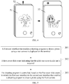
- the user holds the terminal with his or her hand, makes one side of the screen to face him or her, and the rear side of the terminal to face towards the opposite direction.
- the first user interface 51 When a first user interface 51 is displayed on the terminal, the rear camera performs view finding, the object of view finding is a subject opposite to the rear camera.
- the first user interface includes a switching button control.
- the front camera When the user slides out the slide rear cover 52 upwardly in accordance with the direction indicated by an arrow and the first user interface 51 is switched to a second user interface 53, the front camera performs view finding.
- the front camera is opposite to the user, and therefore, an image of view finding is a portrait of the user.
- FIG. 5 is a flowchart of a shooting interface switching method according to an aspect of the present disclosure. Using a scenario where the method is applied to the terminal as illustrated in FIG. 3 as an example, the method includes the following steps:
- Step 301 A first user interface is displayed on the terminal.
- a shooting program may shoot a photo by using a rear camera.
- the first user interface may display previews of real time image data obtained by the rear camera.
- the first user interface may also include other preset buttons or menus for the user to shoot photos using the rear camera. In other words, the first use interface enables the shooting program to shoot a photo using the rear camera.
- the terminal is provided with a slide rear cover. At least one front camera and at least one rear camera are arranged on the terminal. The at least one front camera and the at least one rear camera are disposed on a cover surface of the slide rear cover of the terminal.
- the terminal is equipped with an operating system and a shooting program.
- the operating system is configured to control the shooting program to switch the first user interface to a second user interface.
- a user starts a shooting program 61 on the terminal, and a first user interface 62 of the shooting program is displayed on the screen of the terminal by means of man-machine interaction.
- the first user interface 62 is a user interface for displaying an image for view finding when the shooting program shoots the photo by using the rear camera.
- Step 302 A first cover slide event indicating that the slide rear cover is slid out is acquired.
- the user slides out the slide rear cover, and the first cover slide event is generated on the terminal.
- the operating system acquires the first cover slide event indicating that the slide rear cover is slid out.
- Step 303 The shooting program is controlled, based on the first cover slide event, to switch the first user interface to the second user interface in which the shooting program shoots the photo by using the front camera.
- the display may show previews of real time image data obtained by the front camera.
- the second user interface may also include other preset buttons or menus for the user to shoot photos using the front camera. In other words, the second use interface enables the shooting program to shoot a photo using the front camera.
- the operating system processes the first cover slide event, and obtains an event that is identifiable by the shooting program.
- the shooting program receives the event, calls the front camera based on the event, and switches the first user interface to the second user interface in which the shooting program shoots the photo by using the front camera.
- the second user interface is a user interface for displaying an image for view finding when the shooting program shoots the photo by using the front camera.
- the shooting program acquires state information of the slide rear cover and operating state information of the front camera by a service interface of the slide rear cover.
- the front camera is in an open state.
- the shooting program calls the front camera, and switches the first user interface displayed on the screen to the second user interface.
- the shooting program acquires the state information of the slide rear cover and the operating state information of the front camera and the rear camera.
- the shooting interface switching method by displaying the first user interface in which the shooting program shoots the photo by using the rear camera on the terminal, acquiring the first cover slide event indicating that the slide rear cover is slid out, and controlling, based on the first cover slide event, the shooting program to switch the first user interface to the second user interface in which the shooting program shoots the photo by using the front camera, the step of manually switching the first user interface to the second user interface after the user slides out the slide rear cover is avoided, and man-machine interaction efficiency is improved.
- the event that is identifiable by the shooting program may be a click simulation event generated when the operating system simulates the user to click the switching button control. Detailed description is given in the embodiment illustrated in FIG. 7 hereinafter.
- FIG. 7 is a flowchart of a shooting interface switching method according to another aspect of the present disclosure. Based on FIG. 5 , step 303 is replaced by step 401 to step 403, and detailed description is given to a method of controlling the shooting program to switch the user interface by the operating system. The method includes the following steps: Step 401: Configuration information corresponding to a switching button control in the shooting program is acquired from a configuration file.
- the switching button control is a control for switchover between the front camera and the rear camera.
- the configuration file is a configuration file defined in the operating system.
- the configuration file includes the configuration information corresponding to the switching button control.
- the configuration information corresponding to the switching button control in the configuration file may be written into the configuration file after a programmer measures the configuration information corresponding to the switching button control in the shooting program by using a measurement tool, or may be written into the configuration file by the operating system and/or a background server by machine learning.
- a machine learning model is configured in the operating system.
- the operating system When the user clicks the switching button control to switch the user interface, the operating system records at least one of interface positional information, identifying information and a version number of the switching button control clicked by the user, and inputs the interface positional information, and/or the identifying information, and/or the version number of the switching button control to the machine learning model.
- the machine learning model outputs a simulation event for simulating click of the switching button control.
- the operating system controls the shooting program to switch the first user interface to the second user interface.
- the configuration information corresponding to the switching button control includes at least one of following parameters: the interface positional information of the switching button control, the identifying information of the switching button control, and the version number of the switching button control.
- the example configuration information includes interface positional information and identifying information of the switching button control, and different shooting programs correspond to different interface positional information and identifying information of the switching button control.
- a shooting program 1 corresponds to interface positional information 1 and identifying information 1
- a shooting program 2 corresponds to interface positional information 2 and identifying information 2.
- Table 1 Shooting program Interface positional information of switching button control Identifying information of switching button control Shooting program 1 Interface positional information 1 Identifying information 1 Shooting program 2 Interface positional information 2 Identifying information 2
- the example configuration information includes the interface positional information, identifying information and version number of the switching button control, and different shooting programs correspond to different interface positional information, identifying information and version numbers of the switching button control.
- a shooting program 3 corresponds to interface positional information 3, identifying information 3 and a version number 3
- a shooting program 4 corresponds to interface positional information 4, identifying information 4 and a version number 4.
- the same shooting program corresponds to different version numbers of the switching button control, and thus the interface positional information and identifying information of the switching button control may also be different.
- the shooting program 4 may correspond to the version number 4 or a version number 5; when the shooting program 4 corresponds to the version number 4, the interface positional information and identifying information of the switching button control are the interface positional information 4 and identifying information 4, respectively.
- the interface positional information and identifying information of the switching button control are interface positional information 5 and identifying information 5, respectively.
- Table 2 Shooting program Interface positional information of switching button control Identifying information of switching button control Version number of switching button control Shooting program 3 Interface positional information 3 Identifying information 3 Version number 3 Shooting program 4 Interface positional information 4 Identifying information 4 Version number 4 Shooting program 4 Interface positional information 5 Identifying information 5 Version number 5
- the operating system loads the configuration information stored in a configuration file.
- the operating system includes an interface switching control program.
- the interface switching control program Upon acquiring the first cover slide event, acquires the configuration information corresponding to the switching button control in the shooting program from the configuration file.
- Step 402 A first simulation event for simulating trigger of the switching button control is generated based on the configuration information of the switching button control.
- the interface switching control program simulates a trigger event for trigger of the switching button control based on the configuration information of the switching button control, and generates the first simulation event.
- the configuration information corresponding to the switching button control includes: interface positional information of the switching button control.
- the interface positional information is used for indicating positional coordinates of the switching button control on the first user interface.
- the interface switching control program generates, based on the interface positional information of the switching button control, a first simulation event for simulating click of the switching button control.
- the interface switching control program simulates a click event on the switching button control based on the interface positional information of the switching button control, and generates the first simulation event.
- the first simulation event is a click simulation event generated based on the configuration information of the switching button control and the first cover slide event.
- the click simulation event is a click event generated by the operating system when the user clicks a screen position corresponding to the interface position of the switching button control on a touch screen, and is not a click event generated by a real clicking action from the user.
- Step 403 The first simulation event is sent to the shooting program.
- the first simulation event is used for triggering the shooting program to switch the first user interface to the second user interface.
- the interface switching control program sends the first simulation event to the shooting program.
- the shooting program receives the first simulation event, that is, the shooting program receives the trigger event generated on the switching button control, and performs the subsequent processes based on the first simulation event. That is, the shooting program calls the front camera, and switches the first user interface to the second user interface.
- the shooting interface switching method by displaying the first user interface in which the shooting program shoots the photo by using the rear camera on the terminal, acquiring the first cover slide event indicating that the slide rear cover is slid out, generating the first simulation event based on the first cover slide event, controlling the shooting program to switch the first user interface to the second user interface by using the first simulation event, the step of manually switching the first user interface to the second user interface after the user slides out the slide rear cover is avoided, and man-machine interaction efficiency is improved.
- FIG. 8 is a flowchart of a shooting interface switching method according to another aspect of the present disclosure. Based on FIG. 7 , step 501 to step 504 are added after step 401 to judge whether the configuration information of the switching button control matches the shooting program. The judgment includes the following steps: Step 501: Identifying information of a target control corresponding to the interface positional information on the first user interface is acquired.
- the configuration information corresponding to the switching button control includes the interface positional information and identifying information of the switching button control.
- the interface positional information is used for indicating the positional coordinates of the switching button control on the first user interface.
- the interface switching control program acquires identifying information of the target control at the positional coordinates indicated by the interface positional information of the switching button control on the first user interface.
- Step 502 Whether the identifying information of the target control matches the identifying information of the switching button control is judged.
- the identifying information of a control is a unique identification of the control.
- the interface switching control program judges whether the identifying information of the target control matches the identifying information of the switching button control. When the identifying information of the target control matches the identifying information of the switching button control, step 503 is performed; and when the identifying information of the target control does not match the identifying information of the switching button control, step 504 is performed.
- Step 503 When the identifying information of the target control matches the identifying information of the switching button control, step 402 is performed.
- Step 504 When the identifying information of the target control does not match the identifying information of the switching button control, the configuration information is updated with a background server.
- the interface switching control program matches the identifying information of the target control with the identifying information of the switching button control.
- the identifying information of the target control does not match the identifying information of the switching button control
- it is determined that the version of the switching button control does not match the version of the configuration information and feedback information indicating that the version of the switching button control does not match the version of the configuration information is sent to the background server.
- the programmer updates the configuration information corresponding to the switching button control based on the feedback information, and delivers updated configuration information corresponding to the switching button control to the terminal.
- the shooting interface switching method by displaying the first user interface in which the shooting program shoots the photo by using the rear camera on the terminal, acquiring the first cover slide event indicating that the slide rear cover is slid out, generating the first simulation event based on the first cover slide event, controlling the shooting program to switch the first user interface to the second user interface by using the first simulation event, the step of manually switching the first user interface to the second user interface after the user slides out the slide rear cover is avoided, and man--machine interaction efficiency is improved.
- the shooting interface switching method by matching the identifying information of the target control with the identifying information of the switching button control, determining that the target control is the switching button control in the shooting program and generating the first simulation event, it is ensured that the shooting program is capable of identifying the first simulation event, such that the subsequent processes are performed, and execution efficiency of the program is improved.
- FIG. 9 is a flowchart of an update method of configuration information according to one aspect of the present disclosure. The method includes the following steps: Step 601: The second version number of the shooting program is acquired.
- the operating system updates the configuration information corresponding to the switching button control; or when the shooting program is started, the interface switching control program in the operating system updates the configuration information corresponding to the switching button control.
- the operating system acquires the second version number of the shooting program.
- the interface switching control program in the operating system acquires the second version number of the shooting program.
- Step 602 When the first version number is different from the second version number, the configuration information is updated with a background server.
- the configuration information corresponding to the switching button control includes the first version number.
- the programmer updates the configuration information corresponding to the switching button control based on the feedback information, and delivers updated configuration information of the switching button control to the terminal.
- the shooting interface switching method by displaying the first user interface in which the shooting program shoots the photo by using the rear camera on the terminal, acquiring the first cover slide event indicating that the slide rear cover is slid out, generating the first simulation event based on the first cover slide event, controlling the shooting program to switch the first user interface to the second user interface by using the first simulation event, the step of manually switching the first user interface to the second user interface after the user slides out the slide rear cover is avoided, and man-machine interaction efficiency is improved.
- the shooting interface switching method by determining that the identifying information of the target control does not match the identifying information of the switching button control and timely updating the configuration information, it is ensured that the shooting program is capable of identifying the first simulation event, such that the subsequent processes are performed, and execution efficiency of the program is improved.
- FIG. 10 is a flowchart of a shooting interface switching method according to another aspect of the present disclosure.
- the method includes the following steps: Step 701: A first user interface in which a shooting program shoots a photo by using a rear camera is displayed on the terminal.
- step 301 in FIG. 5 reference may be made to step 301 in FIG. 5 , which is not described herein any further.
- Step 702 An action at the stack top of an action stack is acquired, wherein the action is used for indicating a foreground display interface on the terminal.
- An interface switching control program acquires the action at the stack top of the action stack, and judges whether a foreground display interface on the terminal indicated by the action at the stack top of the action stack is the first user interface.
- Step 703 When the action indicates the front display interface is the first user interface, the step of acquiring a first cover slide event indicating that the slide rear cover is slid out is performed.
- Step 704 The first cover slide event indicating that the slide rear cover is slid out is monitored by a cover slide event controller.
- the operating system includes a cover slide event controller and an interface switching control program.
- a cover slide event controller When a user slides out the slide rear cover, the first cover slide event is generated on the terminal.
- the cover slide event controller monitors the cover slide event.
- Step 705 The first cover slide event is acquired from the cover slide event controller.
- the interface switching control program acquires the first cover slide event indicating that the slide rear cover is slid out from the cover slide event controller.
- Step 706 The shooting program is controlled, based on the first cover slide event, to switch the first user interface to the second user interface in which the shooting program shoots the photo by using the front camera.
- step 303 in FIG. 5 reference may be made to step 303 in FIG. 5 , which is not described herein any further.
- Step 707 A second cover slide event indicating that the slide rear cover is slid in is acquired.
- the operating system includes a cover slide event controller and the interface switching control program.
- the user slides in the slide rear cover, and the second cover slide event is generated on the terminal.
- the cover slide event controller monitors the cover slide event.
- the interface switching control program acquires the second cover slide event indicating that the slide rear cover is slid out from the cover slide event controller.
- Step 708 The shooting program is controlled, based on the second cover slide event, to switch the second user interface to the first user interface.
- the interface switching control program acquires the corresponding information of the switching button control in the shooting program from the configuration file; a second simulation event for simulating trigger of the switching button control is generated based on the configuration information of the switching button control; and the second simulation event is sent to the shooting program.
- the second simulation event is used for triggering the shooting program to switch the second user interface to the first user interface. After the shooting program receives the second simulation event, the second user interface is switched to the first user interface.
- the configuration information corresponding to the switching button control includes: interface positional information of the switching button control.
- the interface positional information is used for indicating positional coordinates of the switching button control on the second user interface.
- the method for generating the second simulation event includes: generating, by the interface switching control program based on the interface positional information of the switching button control, a second simulation event for simulating click of the switching button control.
- the shooting interface switching method by displaying the first user interface in which the shooting program shoots the photo by using the rear camera on the terminal, acquiring the first cover slide event indicating that the slide rear cover is slid out, and controlling, based on the first cover slide event, the shooting program to switch the first user interface to the second user interface in which the shooting program shoots the photo by using the front camera, the step of manually switching the first user interface to the second user interface after the user slides out the slide rear cover is avoided, and man-machine interaction efficiency is improved.
- the shooting interface switching method by monitoring the first cover slide event upon displaying the first user interface on the terminal and timely acquiring the first cover slide event, it is ensured execution efficiency of the shooting interface switching method according to the present disclosure.
- power consumption of the terminal is lowered relative to the scenario where the first cover slide event is monitored in the entire operation process of the terminal, and then the first cover slide event is monitored when the first user interface is displayed on the terminal and the sequent steps are performed.
- the shooting interface switching method by controlling the shooting program to switch the second user interface to the first user interface based on the second cover slide event indicating that the slide rear cover is slid in, the step of manually sliding in the slide rear cover after the user switches the first user interface to the second user interface is avoided, and man-machine interaction efficiency is improved.
- the terminal is equipped with a facial treatment camera; after the user starts the facial treatment camera, the user interface is a user interface in which the shooting program shoots the photo by using the rear camera; and if the user desires to shoots a photo thereof, the user needs to slide out the slide rear cover, click the switching button control and switch to a user interface in a self-portrait mode, that is, a user interface in which the photo is shot by using the front camera.
- the shooting interface switching method according to one or more embodiments, the user only needs to slide out the slide rear cover, and the user interface can be automatically switched to the user interface in the self-portrait mode. Therefore, the man-machine interaction efficiency is improved.
- FIG. 11 is a block diagram of a shooting interface switching apparatus according to one aspect of the present disclosure.
- the apparatus is implemented as a part or an entirety of the terminal by software or hardware or a combination of software and hardware.
- the apparatus includes:
- control module 803 includes:
- the configuration information includes: interface positional information of the switching button control, wherein the interface positional information is used for indicating positional coordinates of the switching button control on the first user interface; and the generating submodule 72 is further configured to generate, based on the interface positional information of the switching button control, a first simulation event for simulating click of the switching button control.
- the configuration information includes: interface positional information and identifying information of the switching button control; and the control module 803 includes:
- the configuration information includes interface positional information and identifying information of the switching button control; and the control module 703 includes:
- the configuration information includes: a first version number; and the control module 803 includes: the acquiring submodule 71, further configured to acquire a second version number of the shooting program; an updating submodule 74, further configured to, when the first version number is different from the second version number, update the configuration information with a background server.
- the acquiring module 802 is further configured to monitor the first cover slide event indicating that the slide rear cover is slid out by a cover slide event controller, and acquire the first cover slide event from the cover slide event controller.
- the apparatus further includes: the acquiring module 802, further configured to acquire an action at the stack top of an action stack, the action being used for indicating a foreground display interface on the terminal; and when the action indicates the foreground display interface is the first user interface, perform the step of acquiring a first cover slide event indicating that the slide rear cover is slid out.
- the apparatus further includes:
- the shooting interface switching apparatus by displaying the first user interface in which the shooting program shoots the photo by using the rear camera on the terminal, acquiring the first cover slide event indicating that the slide rear cover is slid out, and controlling, based on the first cover slide event, the shooting program to switch the first user interface to the second user interface in which the shooting program shoots the photo by using the front camera, the step of manually switching the first user interface to the second user interface after the user slides out the slide rear cover is avoided, and man-machine interaction efficiency is improved.
- the shooting interface switching apparatus by monitoring the first cover slide event upon displaying the first user interface on the terminal and timely acquiring the first cover slide event, it is ensured execution efficiency of the shooting interface switching method according to the present disclosure.
- power consumption of the terminal is lowered relative to the scenario where the first cover slide event is monitored in the entire process where the terminal is operating, and then the first cover slide event is monitored when the first user interface is displayed on the terminal and the sequent steps are performed.
- the configuration information can also be updated timely. This ensures that the shooting program is capable of identifying the first simulation event, and the subsequent processes are performed. Therefore, execution efficiency of the program is improved.
- An aspect of the present disclosure provides a shooting interface switching apparatus, which may implement the shooting interface switching method provided by the present disclosure, the shooting interface switching apparatus comprising: a processor and a memory arranged to store an instruction executable by the processor.
- the processor is arranged to: display a first user interface in which a shooting program shoots a photo by using the rear camera on the terminal; acquire a first cover slide event indicating that the slide rear cover is slid out; and control, based on the first cover slide event, the shooting program to switch the first user interface to a second user interface in which the shooting program shoots a photo by using the front camera.
- FIG. 12 is a block diagram of a shooting interface switching apparatus 1000 shown according to another aspect of the present disclosure.
- the apparatus 1000 may be a mobile phone, a computer, a digital broadcast terminal, a messaging device, a gaming console, a tablet device, a medical device, a fitness equipment, a personal digital assistant, and the like.
- the apparatus 1000 may include one or more of the following components: a processing component 1002, a memory 1004, a power component 1006, a multimedia component 1008, an audio component 1010, an input/output (I/O) interface 1012, a sensor component 1014, and a communication component 1016.
- the processing component 1002 typically controls the overall operations of the apparatus 1000, such as the operations associated with display, telephone calls, data communications, camera operations, and recording operations.
- the processing component 1002 may include one or more processors 1018 to execute instructions to perform all or part of the steps in the above described methods.
- the processing component 1002 may include one or more modules which facilitate the interaction between the processing component 1002 and other components.
- the processing component 1002 may include a multimedia module to facilitate the interaction between the multimedia component 1008 and the processing component 1002.
- the memory 1004 is configured to store various types of data to support the operation of the apparatus 1000. Examples of such data include instructions, contact data, phonebook data, messages, pictures, videos and the like for any programs or methods operated on the apparatus 1000.
- the memory 1004 may be implemented by using any type of volatile or non-volatile memory devices, or a combination thereof, such as a static random access memory (SRAM), an electrically erasable programmable read-only memory (EEPROM), an erasable programmable read-only memory (EPROM), a programmable read-only memory (PROM), a read-only memory (ROM), a magnetic memory, a flash memory, a magnetic or optical disk.
- SRAM static random access memory
- EEPROM electrically erasable programmable read-only memory
- EPROM erasable programmable read-only memory
- PROM programmable read-only memory
- ROM read-only memory
- magnetic memory a magnetic memory
- flash memory a flash memory
- magnetic or optical disk a magnetic
- the power component 1006 provides power to various components of the apparatus 1000.
- the power component 1006 may include a power management system, one or more power sources, and any other components associated with the generation, management, and distribution of power in the apparatus 1000.
- the multimedia component 1008 includes a screen providing an output interface between the apparatus 1000 and the user.
- the screen may include a liquid crystal display (LCD) and a touch panel (TP). If the screen includes the touch panel, the screen may be implemented as a touch screen to receive input signals from the user.
- the touch panel includes one or more touch sensors to sense touches, swipes, and gestures on the touch panel. The touch sensors may not only sense a boundary of a touch or swipe action, but also sense the duration and pressure associated with the touch or swipe action.
- the multimedia component 1008 includes a front camera and/or a rear camera. The front camera and the rear camera may receive external multimedia data while the apparatus 1000 is in an operation mode, such as a photographing mode or a video mode. Each of the front camera and the rear camera may be a fixed optical lens system or have focus and optical zoom capability.
- the audio component 1010 is configured to output and/or input audio signals.
- the audio component 1010 includes a microphone (MIC).
- the microphone configured to receive external audio signals when the apparatus 1000 is in an operation mode, such as a call mode, a recording mode and a voice recognition mode.
- the received audio signal may be further stored in the memory 1004 or transmitted via the communication component 1016.
- the audio component 1010 further includes a speaker for outputting audio signals.
- the I/O interface 1012 provides an interface between the processing component 1002 and peripheral interface modules, such as a keyboard, a click wheel, buttons, and the like.
- the buttons may include, but are not limited to, a home button, a volume button, a start button, and a lock button.
- the sensor component 1014 includes one or more sensors to provide status assessments of various aspects of the apparatus 1000. For instance, the sensor component 1014 may detect an on/off status of the apparatus 1000, relative positioning of components, e.g., the display device and the mini keyboard of the apparatus 1000. The sensor component 1014 may also detect a position change of the apparatus 1000 or a component of the apparatus 1000, presence or absence of user contact with the apparatus 1000, orientation or acceleration/deceleration of the apparatus 1000, and temperature change of the apparatus 1000. The sensor component 1014 may include a proximity sensor configured to detect the presence of nearby objects without any physical contact. The sensor component 1014 may also include a light sensor, such as a CMOS or CCD image sensor, used for imaging applications. In some embodiments, the sensor component 1014 may also include an accelerometer sensor, a gyroscope sensor, a magnetic sensor, a pressure sensor or a temperature sensor.
- the communication component 1016 is configured to facilitate communication, wired or wirelessly, between the apparatus 1000 and other devices.
- the apparatus 1000 can access a wireless network based on a communication standard, such as WiFi, 2G or 3G, or a combination thereof.
- the communication component 1016 receives broadcast signals or broadcast associated information from an external broadcast management system via a broadcast channel.
- the communication component 1016 further includes a near field communication (NFC) module to facilitate short-range communications.
- NFC near field communication
- the apparatus 1000 may be implemented with one or more application specific integrated circuits (ASICs), digital signal processors (DSPs), digital signal processing devices (DSPDs), programmable logic devices (PLDs), field programmable gate arrays (FPGAs), controllers, micro-controllers, microprocessors or other electronic components, for performing the above described method embodiments of the shooting interface switching methods.
- ASICs application specific integrated circuits
- DSPs digital signal processors
- DSPDs digital signal processing devices
- PLDs programmable logic devices
- FPGAs field programmable gate arrays
- controllers micro-controllers, microprocessors or other electronic components, for performing the above described method embodiments of the shooting interface switching methods.
- a non-transitory computer-readable storage medium including instructions is also provided, such as the memory 1004 including instructions, executable by the processor 1018 in the apparatus 1000, for performing the above described method embodiments of the shooting interface switching methods.
- the non-transitory computer-readable storage medium may be a ROM, a RAM, a CD-ROM, a magnetic tape, a floppy disc, an optical data storage device, and the like.
- the computer-readable storage medium is non-volatile computer-readable storage medium and stores therein computer programs that, when executed on a processing component, implement the shooting interface switching methods according to the embodiments of the present disclosure.
- An embodiment of the present disclosure further provides a computer program product.
- the computer program product stores instructions, which, when being executed on a computer, cause the computer to perform the shooting interface switching methods according to the embodiments of the present disclosure.
- An embodiment of the present disclosure further provides a chip.
- the chip includes a programmable logic circuit and/or a program instruction.
- the chip when being ran, performs the shooting interface switching methods according to the embodiments of the present disclosure.
Landscapes
- Engineering & Computer Science (AREA)
- Signal Processing (AREA)
- Multimedia (AREA)
- Theoretical Computer Science (AREA)
- Human Computer Interaction (AREA)
- General Engineering & Computer Science (AREA)
- Physics & Mathematics (AREA)
- General Physics & Mathematics (AREA)
- Computer Hardware Design (AREA)
- Computer Networks & Wireless Communication (AREA)
- Software Systems (AREA)
- Environmental & Geological Engineering (AREA)
- Mathematical Physics (AREA)
- User Interface Of Digital Computer (AREA)
- Studio Devices (AREA)
- Stored Programmes (AREA)
- Telephone Function (AREA)
Abstract
Description
- Embodiments of the present disclosure relate to the field of camera shooting technology, and in particular, to a shooting interface switching method and apparatus, and a device and storage medium thereof
- At present, most commercially available smart phones are equipped with a front camera and a rear camera. The front camera is arranged on the side with the screen, and the rear camera is arranged on a rear side of the smart phone.
- In the related art, after a user starts the camera on a smart phone, a user interface in which photos are shot by using the rear camera is generally displayed on the screen of the smart phone. In this case, the smart phone finds views and acquires images by using the rear camera. The user interface is further provided with a switching button control. If the user desires to shoot a photo by using the front camera, the user may switch the rear camera to the front camera only by clicking the switching button control on the user interface. In this case, the smart phone finds views and acquires images by using the front camera, and a user interface in which photos are shot by using the front camera is displayed on the screen of the smart phone.
- Embodiments of the present disclosure provide a shooting interface switching method and apparatus, and a device and a storage medium thereof. The technical solutions are as follows:
- According to the first aspect of the present disclosure, there is provided a shooting interface switching method, the method comprising: displaying a first user interface that enables a shooting program to shoot a photo using the rear camera on the terminal; acquiring a first cover slide event indicating that the slide rear cover is slid out; and controlling, based on the first cover slide event, the shooting program to switch the first user interface to a second user interface that enables the shooting program to shoot a photo by using the front camera.
- In some embodiments, the controlling the shooting program to switch the first user interface to a second user interface that enables a shooting program to shoot a photo using the front camera comprises:
- acquiring configuration information corresponding to a switching button control in the shooting program from a configuration file, the switching button control being a control for switching the front camera and the rear camera;
- generating, based on the configuration information of the switching button control, a first simulation event for simulating trigger of the switching button control; and
- sending the first simulation event to the shooting program, the first simulation event being used for triggering the shooting program to switch the first user interface to the second user interface.
- In some embodiments, the configuration information comprises: interface positional information of the switching button control, the interface positional information being used for indicating positional coordinates of the switching button control on the first user interface; and
the generating, based on the configuration information of the switching button control, a first simulation event for simulating trigger of the switching button control comprises:
generating, based on the interface positional information of the switching button control, a first simulation event for simulating click of the switching button control. - In some embodiments, the configuration information comprises: interface positional information and identifying information of the switching button control; and the method further comprises:
- acquiring identifying information of a target control corresponding to the interface positional information on the first user interface; and
- when the identifying information of the target control matches the identifying information of the switching button control, performing the step of generating, based on the configuration information of the switching button control, a first simulation event for simulating trigger of the switching button control.
- In some embodiments, the configuration information comprises: interface positional information and identifying information of the switching button control; and the method further comprises:
- acquiring identifying information of a target control corresponding to the interface positional information on the first user interface; and
- when the identifying information of the target control does not match the identifying information of the switching button control, updating the configuration information with a background server.
- In some embodiments, the configuration information comprises: a first version number; and the method further comprises:
- acquiring a second version number of the shooting program; and
- when the first version number is different from the second version number, updating the configuration information with a background server.
- In some embodiments, the acquiring a first cover slide event indicating that the slide rear cover is slid out comprises:
- monitoring the first cover slide event indicating that the slide rear cover is slid out by a cover slide event controller; and
- acquiring the first cover slide event from the cover slide event controller.
- In some embodiments, the method further comprising:
- acquiring an action at the stack top of an action stack, the action being used for indicating a foreground display interface on the terminal; and
- when the action indicates the foreground interface is the first user interface, performing the step of acquiring a first cover slide event indicating that the slide rear cover is slid out.
- In some embodiments, the method further comprising:
- acquiring a second cover slide event indicating that the slide rear cover is slid in; and
- controlling, based on the second cover slide event, the shooting program to switch the second user interface to the first user interface.
- According to the second aspect of the present disclosure, there is provided a shooting interface switching apparatus, the apparatus comprising:
- a display module, configured to display a first user interface that enables a shooting program to shoot a photo using a rear camera on a terminal;
- an acquiring module, configured to acquire a first cover slide event indicating that a slide rear cover is slid out in a first position; and
- a control module, configured to control, based on the first cover slide event, the shooting program to switch the first user interface to a second user interface that enables a shooting program to shoot a photo using a front camera.
- In some embodiments, the control module comprises:
- an acquiring submodule, configured to acquire configuration information corresponding to a switching button control in the shooting program from a configuration file, the switching button control being a control for switching the front camera and the rear camera;
- a generating submodule, configured to generate, based on the configuration information of the switching button control, a first simulation event for simulating trigger of the switching button control; and
- a sending submodule, configured to send the first simulation event to the shooting program, the first simulation event being used for triggering the shooting program to switch the first user interface to the second user interface.
- In some embodiments, the configuration information comprises: interface positional information of the switching button control, the interface positional information being used for indicating positional coordinates of the switching button control on the first user interface; and
the generating submodule, further configured to generate, based on the interface positional information of the switching button control, a first simulation event for simulating click of the switching button control. - In some embodiments, the configuration information comprises interface positional information and identifying information of the switching button control; and the control module comprises:
- the acquiring submodule, further configured to acquire identifying information of a target control corresponding to the interface positional information on the first user interface; and
- the generating submodule, further configured to, when the identifying information of the target control matches the identifying information of the switching button control, perform the step of generating, based on the configuration information of the switching button control, a first simulation event for simulating trigger of the switching button control.
- In some embodiments, the configuration information comprises interface positional information and identifying information of the switching button control; and the control module comprises:
- the acquiring submodule, further configured to acquire identifying information of a target control corresponding to the interface positional information on the first user interface; and
- a updating submodule, further configured to, when the identifying information of the target control does not match the identifying information of the switching button control, update the configuration information with a background server.
- In some embodiments, the configuration information comprises: a first version number; and the control module comprises:
- the acquiring submodule, further configured to acquire a second version number of the shooting program; and
- a updating submodule, further configured to, when the first version number is different from the second version number, update the configuration information with a background server.
- In some embodiments,
the acquiring module, further configured to monitor the first cover slide event indicating that the slide rear cover is slid out by a cover slide event controller, and acquire the first cover slide event from the cover slide event controller. - In some embodiments, the apparatus further comprises:
the acquiring module, further configured to acquire an action at the stack top of an action stack, the action being used for indicating a foreground display interface on the terminal; and when the action indicates the foreground display interface is the first user interface, perform the step of acquiring a first cover slide event indicating that the slide rear cover is slid out in the first position. - In some embodiments, the apparatus further comprises:
- the acquiring module, further configured to acquire a second cover slide event indicating that the slide rear cover is slid in in a second position; and
- the control module, further configured to control, based on the second cover slide event, the shooting program to switch the second user interface to the first user interface.
- According to the third aspect of the present disclosure, there is provided a terminal, comprising a processor and a memory; wherein the memory stores at least one instruction, at least one program, a code set or an instruction set, the at least one instruction, the at least one program, the code set or the instruction set being loaded and executed by the processor to perform the shooting interface switching method as defined in the first aspect.
- According to the fourth aspect of the present disclosure there is provided a terminal comprising a screen display preferably built as full screen display; a slight rear cover attached to the screen display inslidable relative to the screen display between a first position and a second position; a rear camera and front camera arranged on a rear surface and a front surface of the slide rear cover wherein in the first position the front camera is exposed an visible and; a display module configured to display a first user interface on the display screen in which a shooting program shots a photo using the rear camera of the terminal; an acquiring module configured to acquire the first cover slide event indicating that the slide rear cover is in the first position and slid out; and a control module configured to control based on the first cover slide event the shooting program to switch the first user interface to a second user interface in which the shooting program shots a photo by using the front camera.
- Further embodiments of the terminal comprise features along with the features of the shooting interface switching apparatus as previous described wherein the features of the shooting interface switching apparatus can be freely combined with the terminal.
- According to the fifth aspect of the present disclosure, there is provided a computer-readable storage medium, wherein the computer-readable storage medium stores at least one instruction, at least one program, a code set or an instruction set, the at least one instruction, the at least one program, the code set or the instruction set being loaded and executed by the processor to perform the shooting interface switching method as defined in the first aspect.
- The technical solutions provided by embodiments of the present disclosure may at least include the following beneficial effects:
By displaying the first user interface that enables a shooting program to shoot a photo using the rear camera on the terminal, acquiring the first cover slide event indicating that the slide rear cover is slid out, and controlling, based on the first cover slide event, the shooting program to switch the first user interface to the second user interface that enables a shooting program to shoot a photo using the front camera, the step of manually switching the first user interface to the second user interface after a user slides out the slide rear cover is avoided, and man-machine interaction efficiency is improved. - To describe the technical solutions in the embodiments of the present disclosure more clearly, the following briefly introduces the accompanying drawings required for describing the embodiments. Apparently, the accompanying drawings in the following description show merely some embodiments of the present disclosure, and a person of ordinary skill in the art may still derive other drawings from these accompanying drawings without creative efforts.
-
FIG. 1 is a structural diagram of a terminal according to one aspect of the present disclosure; -
FIG. 2 is a structural diagram of a terminal according to another aspect of the present disclosure; -
FIG. 3 is a structural diagram of a terminal according to another aspect of the present disclosure; -
FIG. 4 is a schematic interface diagram of a shooting interface switching method according to one aspect of the present disclosure; -
FIG. 5 is a flowchart of a shooting interface switching method according to one aspect of the present disclosure; -
FIG. 6 is a schematic interface diagram of a shooting interface switching method according to another aspect of the present disclosure; -
FIG. 7 is a flowchart of a shooting interface switching method according to another aspect of the present disclosure; -
FIG. 8 is a flowchart of a shooting interface switching method according to another aspect of the present disclosure; -
FIG. 9 is a flowchart of an update method of configuration information according to one aspect of the present disclosure; -
FIG. 10 is a flowchart of a shooting interface switching method according to another aspect of the present disclosure; -
FIG. 11 is a block diagram of a shooting interface switching apparatus according to one aspect of the present disclosure; and -
FIG. 12 is a block diagram of a shooting interface switching apparatus according to another aspect of the present disclosure. - The present disclosure will be described in further detail with reference to the accompanying drawings, to present the objects, technical solutions, and advantages of the present disclosure clearer.
- The employing of full screen display changes the position of the front camera of a terminal. Some front cameras are arranged inside the terminal, and the front camera may eject out from the edge when a related function is enabled.
- Another solution of employing the front camera of the terminal supporting full screen display is separating the front camera from the screen by a slide rear cover. In a cover type terminal, the front camera and the rear camera are respectively arranged on a front surface and a rear surface of the slide rear cover. Reference may be schematically made to a rear side view as illustrated in
FIG. 1 . The terminal is provided with a sliderear cover 101, wherein arear camera 11 is arranged on the rear surface of the sliderear cover 101. Referring to a front side view as illustrated inFIG. 2 , when the sliderear cover 101 is upwardly (or downwardly) slid out from a retraced position to an external position, the front surface of the sliderear cover 101 is provided with afront camera 12. - During the use of the slide-cover terminal, after a user starts a shooting program, generally a first user interface in which the shooting program shoots a photo by using the
rear camera 11 is displayed on the screen of the terminal. If the user desires to shoot and acquire an image by using thefront camera 12, the user needs to slide out the sliderear cover 101 firstly, and then click a switching button control on the first user interface to switch the first user interface to a second user interface in which the shooting program shoots a photo by using the front camera. The steps are as follows: - 1. starting the shooting program, and displaying the first user interface on the terminal;
- 2. sliding out the slide rear cover; and
- 3. clicking a switching button control, to switch from the first user interface to the second user interface.
- In the above process, switching of the user interface may be completed through at least three steps. However, switching of the user interface on a terminal where the front camera is arranged on the screen thereof may be completed through two steps:
- 1. starting the shooting program, and displaying the first user interface on the terminal; and
- 2. clicking the switching button control, to switch from the first user interface to the second user interface.
- As such, when the slide-cover terminal shoots the photo by using the front camera, the user interface switching steps are more complicated.
- To solve the technical problem that the above steps are complicated, the present disclosure provides a shooting interface switching method and apparatus, and a device and storage medium thereof. The shooting interface switching method and apparatus, and the device and the storage medium thereof are described with reference to the embodiments hereinafter.
-
FIG. 3 is a structural diagram of a terminal according to an aspect of the present disclosure. The terminal 200 includes: anapplication layer 201, anoperating system layer 202 and aphysical layer 203. - A
shooting program 21 is installed and ran on theapplication layer 201. Theshooting program 21 may be a photo shooting program configured to execute an operation instruction sent by theoperating system layer 202 and practice image shooting. For example, theshooting program 21 may be a shooting program originally equipped in the operating system, or a shooting program provided by a third party. - Optionally, the shooting program provided by the third party may be carried and installed in the operating system, or may be downloaded and installed by a user.
- The shooting program originally equipped in the operating system may refer to a shooting program provided by a service provider that provides the operating system. The shooting program provided by the third party may refer to a shooting program provided by a third party service provider besides the service provider that provides the operating system; and the third party refers to a service provider besides the service provider that provides the operating system.
- The
operating system layer 202 is provided with an interfaceswitching control program 31, anaction stack 32, aservice interface 33 of the slide rear cover and a cover slide event controller 24. - The interface
switching control program 31 is a program block configured to control theshooting program 21 to switch the first user interface to the second user interface, or switch the second user interface to the first user interface. The first user interface is a user interface in which the shooting program shoots the photo by using arear camera 43, and the second user interface is a user interface that enables the shooting program to shoot a photo by using afront camera 42. - The
action stack 32 is a return stack configured to manage actions. The action is a component including the user interface, and is configured to implement interactions with the user. Each application may include a plurality of actions. The actions may be superimposed. Each time a new action is started, the newly started action can be superimposed over an original action. In the operating system, started actions are stored in theaction stack 32. Theaction stack 32 is a last-in first-out data structure. By default, each time a new action is started, the new action can be pushed onto theaction stack 32, and placed at the stack top of the action stack. The action at the stack top is an action active at the foreground. The action active at the foreground is a component corresponding to a user interface that is located at an uppermost layer. The user interface located at the uppermost layer is a user interface that is visible on the screen by the user when using the terminal. Exemplarily, in the present disclosure, the first user interface is displayed on the terminal, the component corresponding to the first user interface is at the stack top of theaction stack 32; when the first user interface is switched to the second user interface, a new action is started in the operating system, that is, the component corresponding to the second user interface; the new action can be pushed onto the action stack, and the component corresponding to the second user interface is superimposed over the component corresponding to the first user interface. In this case, the component corresponding to the second user interface is at the stack top of theaction stack 32, and the second user interface is displayed on the screen of the terminal. - The
service interface 33 of the slide rear cover is a service interface arranged in theoperating system layer 202, and is used by theshooting program 21 to acquire state information of the slide rear cover. - The cover
slide event controller 34 is configured to monitor slide-out and slide-in events of a sliderear cover 41, and send the slide-out and slide-in events of the sliderear cover 41 to the interfaceswitching control program 31. - The
physical layer 303 includes a sliderear cover 41, afront camera 42 and arear camera 43. Thefront camera 42 and therear camera 43 are respectively arranged on the front surface and the rear surface of the sliderear cover 41. Reference may be made to the exemplary description inFIG. 1 and FIG. 2 , which is not described herein any further. The user slides the sliderear cover 41 to generate slide-out and slide-in events, and the coverslide event controller 34 monitors the generated slide-out and slide-in events and sends the slide-out and slide-in events to the interfaceswitching control program 31. Thefront camera 42 and therear camera 43 are configured to find views during image shooting. - Exemplarily, the first user interface in which the
shooting program 21 shoots the photo by using therear camera 43 is displayed on the terminal; the user slides out the sliderear cover 41 and generates the first cover slide event; upon monitoring the first cover slide event, the coverslide event controller 34 sends the first cover slide event to the interfaceswitching control program 31; and the interfaceswitching control program 31 controls, based on the first cover slide event, the first user interface to the second user interface in which theshooting program 21 shoots the photo by using thefront camera 42. Referring toFIG. 4 , the user holds the terminal with his or her hand, makes one side of the screen to face him or her, and the rear side of the terminal to face towards the opposite direction. When afirst user interface 51 is displayed on the terminal, the rear camera performs view finding, the object of view finding is a subject opposite to the rear camera. The first user interface includes a switching button control. When the user slides out the sliderear cover 52 upwardly in accordance with the direction indicated by an arrow and thefirst user interface 51 is switched to asecond user interface 53, the front camera performs view finding. The front camera is opposite to the user, and therefore, an image of view finding is a portrait of the user. -
FIG. 5 is a flowchart of a shooting interface switching method according to an aspect of the present disclosure. Using a scenario where the method is applied to the terminal as illustrated inFIG. 3 as an example, the method includes the following steps: - Step 301: A first user interface is displayed on the terminal. In the first user interface, a shooting program may shoot a photo by using a rear camera. The first user interface may display previews of real time image data obtained by the rear camera. The first user interface may also include other preset buttons or menus for the user to shoot photos using the rear camera. In other words, the first use interface enables the shooting program to shoot a photo using the rear camera.
- The terminal is provided with a slide rear cover. At least one front camera and at least one rear camera are arranged on the terminal. The at least one front camera and the at least one rear camera are disposed on a cover surface of the slide rear cover of the terminal.
- The terminal is equipped with an operating system and a shooting program. The operating system is configured to control the shooting program to switch the first user interface to a second user interface.
- Exemplarily, referring to
FIG. 6 , a user starts ashooting program 61 on the terminal, and afirst user interface 62 of the shooting program is displayed on the screen of the terminal by means of man-machine interaction. Thefirst user interface 62 is a user interface for displaying an image for view finding when the shooting program shoots the photo by using the rear camera. - Step 302: A first cover slide event indicating that the slide rear cover is slid out is acquired.
- The user slides out the slide rear cover, and the first cover slide event is generated on the terminal. The operating system acquires the first cover slide event indicating that the slide rear cover is slid out.
- Step 303: The shooting program is controlled, based on the first cover slide event, to switch the first user interface to the second user interface in which the shooting program shoots the photo by using the front camera. In the second user interface, the display may show previews of real time image data obtained by the front camera. The second user interface may also include other preset buttons or menus for the user to shoot photos using the front camera. In other words, the second use interface enables the shooting program to shoot a photo using the front camera.
- The operating system processes the first cover slide event, and obtains an event that is identifiable by the shooting program. The shooting program receives the event, calls the front camera based on the event, and switches the first user interface to the second user interface in which the shooting program shoots the photo by using the front camera. The second user interface is a user interface for displaying an image for view finding when the shooting program shoots the photo by using the front camera.
- Optionally, prior to calling the front camera, the shooting program acquires state information of the slide rear cover and operating state information of the front camera by a service interface of the slide rear cover. When the slide rear cover is in a slid-out state, the front camera is in an open state. Upon determining that the front camera is in an idle state based on the operating state information, the shooting program calls the front camera, and switches the first user interface displayed on the screen to the second user interface. By the service interface of the slide rear cover, the shooting program acquires the state information of the slide rear cover and the operating state information of the front camera and the rear camera.
- In summary, in the shooting interface switching method according to one or more embodiments, by displaying the first user interface in which the shooting program shoots the photo by using the rear camera on the terminal, acquiring the first cover slide event indicating that the slide rear cover is slid out, and controlling, based on the first cover slide event, the shooting program to switch the first user interface to the second user interface in which the shooting program shoots the photo by using the front camera, the step of manually switching the first user interface to the second user interface after the user slides out the slide rear cover is avoided, and man-machine interaction efficiency is improved.
- It should be noted that the event that is identifiable by the shooting program may be a click simulation event generated when the operating system simulates the user to click the switching button control. Detailed description is given in the embodiment illustrated in
FIG. 7 hereinafter. -
FIG. 7 is a flowchart of a shooting interface switching method according to another aspect of the present disclosure. Based onFIG. 5 ,step 303 is replaced bystep 401 to step 403, and detailed description is given to a method of controlling the shooting program to switch the user interface by the operating system. The method includes the following steps:
Step 401: Configuration information corresponding to a switching button control in the shooting program is acquired from a configuration file. - The switching button control is a control for switchover between the front camera and the rear camera.
- The configuration file is a configuration file defined in the operating system. The configuration file includes the configuration information corresponding to the switching button control. Optionally, the configuration information corresponding to the switching button control in the configuration file may be written into the configuration file after a programmer measures the configuration information corresponding to the switching button control in the shooting program by using a measurement tool, or may be written into the configuration file by the operating system and/or a background server by machine learning. Exemplarily, a machine learning model is configured in the operating system. When the user clicks the switching button control to switch the user interface, the operating system records at least one of interface positional information, identifying information and a version number of the switching button control clicked by the user, and inputs the interface positional information, and/or the identifying information, and/or the version number of the switching button control to the machine learning model. The machine learning model outputs a simulation event for simulating click of the switching button control. By the simulation event, the operating system controls the shooting program to switch the first user interface to the second user interface.
- Optionally, the configuration information corresponding to the switching button control includes at least one of following parameters: the interface positional information of the switching button control, the identifying information of the switching button control, and the version number of the switching button control.
- For example, referring to Table 1, the example configuration information includes interface positional information and identifying information of the switching button control, and different shooting programs correspond to different interface positional information and identifying information of the switching button control. For example, a shooting program 1 corresponds to interface positional information 1 and identifying information 1, and a shooting program 2 corresponds to interface positional information 2 and identifying information 2.
Table 1 Shooting program Interface positional information of switching button control Identifying information of switching button control Shooting program 1 Interface positional information 1 Identifying information 1 Shooting program 2 Interface positional information 2 Identifying information 2 - Referring to Table 2, the example configuration information includes the interface positional information, identifying information and version number of the switching button control, and different shooting programs correspond to different interface positional information, identifying information and version numbers of the switching button control. For example, a shooting program 3 corresponds to interface positional information 3, identifying information 3 and a version number 3, and a shooting program 4 corresponds to interface positional information 4, identifying information 4 and a version number 4. Alternatively, the same shooting program corresponds to different version numbers of the switching button control, and thus the interface positional information and identifying information of the switching button control may also be different. For example, the shooting program 4 may correspond to the version number 4 or a version number 5; when the shooting program 4 corresponds to the version number 4, the interface positional information and identifying information of the switching button control are the interface positional information 4 and identifying information 4, respectively. When the shooting program 4 corresponds to the version number 5, the interface positional information and identifying information of the switching button control are interface positional information 5 and identifying information 5, respectively.
Table 2 Shooting program Interface positional information of switching button control Identifying information of switching button control Version number of switching button control Shooting program 3 Interface positional information 3 Identifying information 3 Version number 3 Shooting program 4 Interface positional information 4 Identifying information 4 Version number 4 Shooting program 4 Interface positional information 5 Identifying information 5 Version number 5 - Optionally, when the terminal is powered on, the operating system loads the configuration information stored in a configuration file.
- The operating system includes an interface switching control program. Upon acquiring the first cover slide event, the interface switching control program acquires the configuration information corresponding to the switching button control in the shooting program from the configuration file.
- Step 402: A first simulation event for simulating trigger of the switching button control is generated based on the configuration information of the switching button control.
- The interface switching control program simulates a trigger event for trigger of the switching button control based on the configuration information of the switching button control, and generates the first simulation event.
- The configuration information corresponding to the switching button control includes: interface positional information of the switching button control. The interface positional information is used for indicating positional coordinates of the switching button control on the first user interface.
- Optionally, the interface switching control program generates, based on the interface positional information of the switching button control, a first simulation event for simulating click of the switching button control.
- Optionally, the interface switching control program simulates a click event on the switching button control based on the interface positional information of the switching button control, and generates the first simulation event.
- The first simulation event is a click simulation event generated based on the configuration information of the switching button control and the first cover slide event. The click simulation event is a click event generated by the operating system when the user clicks a screen position corresponding to the interface position of the switching button control on a touch screen, and is not a click event generated by a real clicking action from the user.
- Step 403: The first simulation event is sent to the shooting program.
- The first simulation event is used for triggering the shooting program to switch the first user interface to the second user interface.
- The interface switching control program sends the first simulation event to the shooting program. The shooting program receives the first simulation event, that is, the shooting program receives the trigger event generated on the switching button control, and performs the subsequent processes based on the first simulation event. That is, the shooting program calls the front camera, and switches the first user interface to the second user interface.
- In sum, in the shooting interface switching method according to one or more embodiments, by displaying the first user interface in which the shooting program shoots the photo by using the rear camera on the terminal, acquiring the first cover slide event indicating that the slide rear cover is slid out, generating the first simulation event based on the first cover slide event, controlling the shooting program to switch the first user interface to the second user interface by using the first simulation event, the step of manually switching the first user interface to the second user interface after the user slides out the slide rear cover is avoided, and man-machine interaction efficiency is improved.
-
FIG. 8 is a flowchart of a shooting interface switching method according to another aspect of the present disclosure. Based onFIG. 7 , step 501 to step 504 are added afterstep 401 to judge whether the configuration information of the switching button control matches the shooting program. The judgment includes the following steps:
Step 501: Identifying information of a target control corresponding to the interface positional information on the first user interface is acquired. - The configuration information corresponding to the switching button control includes the interface positional information and identifying information of the switching button control. The interface positional information is used for indicating the positional coordinates of the switching button control on the first user interface. The interface switching control program acquires identifying information of the target control at the positional coordinates indicated by the interface positional information of the switching button control on the first user interface.
- Step 502: Whether the identifying information of the target control matches the identifying information of the switching button control is judged.
- The identifying information of a control is a unique identification of the control. The interface switching control program judges whether the identifying information of the target control matches the identifying information of the switching button control. When the identifying information of the target control matches the identifying information of the switching button control,
step 503 is performed; and when the identifying information of the target control does not match the identifying information of the switching button control,step 504 is performed. - Step 503: When the identifying information of the target control matches the identifying information of the switching button control,
step 402 is performed. - Step 504: When the identifying information of the target control does not match the identifying information of the switching button control, the configuration information is updated with a background server.
- The interface switching control program matches the identifying information of the target control with the identifying information of the switching button control. When the identifying information of the target control does not match the identifying information of the switching button control, it is determined that the version of the switching button control does not match the version of the configuration information, and feedback information indicating that the version of the switching button control does not match the version of the configuration information is sent to the background server. In this case, the programmer updates the configuration information corresponding to the switching button control based on the feedback information, and delivers updated configuration information corresponding to the switching button control to the terminal.
- In summary, in the shooting interface switching method according to one or more embodiments, by displaying the first user interface in which the shooting program shoots the photo by using the rear camera on the terminal, acquiring the first cover slide event indicating that the slide rear cover is slid out, generating the first simulation event based on the first cover slide event, controlling the shooting program to switch the first user interface to the second user interface by using the first simulation event, the step of manually switching the first user interface to the second user interface after the user slides out the slide rear cover is avoided, and man--machine interaction efficiency is improved.
- In the shooting interface switching method according to one or more embodiments, by matching the identifying information of the target control with the identifying information of the switching button control, determining that the target control is the switching button control in the shooting program and generating the first simulation event, it is ensured that the shooting program is capable of identifying the first simulation event, such that the subsequent processes are performed, and execution efficiency of the program is improved.
- It should be noted that when a first version number in the configuration information does not match a second version number of the shooting program, the configuration information needs to be updated. Update of the configuration information may be completed when the terminal is powered on or when the shooting program is started. Referring to
FIG. 9, FIG. 9 is a flowchart of an update method of configuration information according to one aspect of the present disclosure. The method includes the following steps:
Step 601: The second version number of the shooting program is acquired. - Optionally, when the terminal is powered on, the operating system updates the configuration information corresponding to the switching button control; or when the shooting program is started, the interface switching control program in the operating system updates the configuration information corresponding to the switching button control.
- In an optional embodiment, when the terminal is powered on, the operating system acquires the second version number of the shooting program.
- In an optional embodiment, when the shooting program is started, the interface switching control program in the operating system acquires the second version number of the shooting program.
- Step 602: When the first version number is different from the second version number, the configuration information is updated with a background server.
- The configuration information corresponding to the switching button control includes the first version number.
- When the first version number is different from the second version number, it is determined that the version of the shooting program does not match the version of the configuration information; and feedback information indicating that the version of the shooting program does not match the version of the configuration information is sent to the background server. In this case, the programmer updates the configuration information corresponding to the switching button control based on the feedback information, and delivers updated configuration information of the switching button control to the terminal.
- In summary, in the shooting interface switching method according to one or more embodiments, by displaying the first user interface in which the shooting program shoots the photo by using the rear camera on the terminal, acquiring the first cover slide event indicating that the slide rear cover is slid out, generating the first simulation event based on the first cover slide event, controlling the shooting program to switch the first user interface to the second user interface by using the first simulation event, the step of manually switching the first user interface to the second user interface after the user slides out the slide rear cover is avoided, and man-machine interaction efficiency is improved.
- In the shooting interface switching method according to one or more embodiments, by determining that the identifying information of the target control does not match the identifying information of the switching button control and timely updating the configuration information, it is ensured that the shooting program is capable of identifying the first simulation event, such that the subsequent processes are performed, and execution efficiency of the program is improved.
-
FIG. 10 is a flowchart of a shooting interface switching method according to another aspect of the present disclosure. Using a scenario where the method is applied to the terminal as illustrated inFIG. 3 as an example, the method includes the following steps:
Step 701: A first user interface in which a shooting program shoots a photo by using a rear camera is displayed on the terminal. - With respect to this step, reference may be made to step 301 in
FIG. 5 , which is not described herein any further. - Step 702: An action at the stack top of an action stack is acquired, wherein the action is used for indicating a foreground display interface on the terminal.
- An interface switching control program acquires the action at the stack top of the action stack, and judges whether a foreground display interface on the terminal indicated by the action at the stack top of the action stack is the first user interface.
- Step 703: When the action indicates the front display interface is the first user interface, the step of acquiring a first cover slide event indicating that the slide rear cover is slid out is performed.
- Step 704: The first cover slide event indicating that the slide rear cover is slid out is monitored by a cover slide event controller.
- The operating system includes a cover slide event controller and an interface switching control program. When a user slides out the slide rear cover, the first cover slide event is generated on the terminal. The cover slide event controller monitors the cover slide event.
- Step 705: The first cover slide event is acquired from the cover slide event controller.
- When the cover slide event controller monitors the first cover slide event, the interface switching control program acquires the first cover slide event indicating that the slide rear cover is slid out from the cover slide event controller.
- Step 706: The shooting program is controlled, based on the first cover slide event, to switch the first user interface to the second user interface in which the shooting program shoots the photo by using the front camera.
- With respect to this step, reference may be made to step 303 in
FIG. 5 , which is not described herein any further. - Step 707: A second cover slide event indicating that the slide rear cover is slid in is acquired.
- The operating system includes a cover slide event controller and the interface switching control program. The user slides in the slide rear cover, and the second cover slide event is generated on the terminal. The cover slide event controller monitors the cover slide event. When the cover slide event controller monitors the second cover slide event, the interface switching control program acquires the second cover slide event indicating that the slide rear cover is slid out from the cover slide event controller.
- Step 708: The shooting program is controlled, based on the second cover slide event, to switch the second user interface to the first user interface.
- Optionally, the interface switching control program acquires the corresponding information of the switching button control in the shooting program from the configuration file; a second simulation event for simulating trigger of the switching button control is generated based on the configuration information of the switching button control; and the second simulation event is sent to the shooting program. The second simulation event is used for triggering the shooting program to switch the second user interface to the first user interface. After the shooting program receives the second simulation event, the second user interface is switched to the first user interface.
- The configuration information corresponding to the switching button control includes: interface positional information of the switching button control. The interface positional information is used for indicating positional coordinates of the switching button control on the second user interface. Optionally, the method for generating the second simulation event includes: generating, by the interface switching control program based on the interface positional information of the switching button control, a second simulation event for simulating click of the switching button control.
- In summary, in the shooting interface switching method according to one or more embodiments, by displaying the first user interface in which the shooting program shoots the photo by using the rear camera on the terminal, acquiring the first cover slide event indicating that the slide rear cover is slid out, and controlling, based on the first cover slide event, the shooting program to switch the first user interface to the second user interface in which the shooting program shoots the photo by using the front camera, the step of manually switching the first user interface to the second user interface after the user slides out the slide rear cover is avoided, and man-machine interaction efficiency is improved.
- In the shooting interface switching method according to one or more embodiments, by monitoring the first cover slide event upon displaying the first user interface on the terminal and timely acquiring the first cover slide event, it is ensured execution efficiency of the shooting interface switching method according to the present disclosure. In addition, power consumption of the terminal is lowered relative to the scenario where the first cover slide event is monitored in the entire operation process of the terminal, and then the first cover slide event is monitored when the first user interface is displayed on the terminal and the sequent steps are performed.
- In addition, in the shooting interface switching method according to one or more embodiments, by controlling the shooting program to switch the second user interface to the first user interface based on the second cover slide event indicating that the slide rear cover is slid in, the step of manually sliding in the slide rear cover after the user switches the first user interface to the second user interface is avoided, and man-machine interaction efficiency is improved.
- For example, the terminal is equipped with a facial treatment camera; after the user starts the facial treatment camera, the user interface is a user interface in which the shooting program shoots the photo by using the rear camera; and if the user desires to shoots a photo thereof, the user needs to slide out the slide rear cover, click the switching button control and switch to a user interface in a self-portrait mode, that is, a user interface in which the photo is shot by using the front camera. In the shooting interface switching method according to one or more embodiments, the user only needs to slide out the slide rear cover, and the user interface can be automatically switched to the user interface in the self-portrait mode. Therefore, the man-machine interaction efficiency is improved.
-
FIG. 11 is a block diagram of a shooting interface switching apparatus according to one aspect of the present disclosure. The apparatus is implemented as a part or an entirety of the terminal by software or hardware or a combination of software and hardware. The apparatus includes: - a
display module 801, configured to display a first user interface in which a shooting program shoots a photo by using a rear camera on a terminal; - an acquiring
module 802, configured to acquire a first cover slide event indicating that a slide rear cover is slid out; and - a
control module 803, configured to control, based on the first cover slide event, the shooting program to switch the first user interface to a second user interface in which the shooting program shoots a photo by using a front camera. - In some embodiments, the
control module 803 includes: - an acquiring
submodule 71, configured to acquire configuration information corresponding to a switching button control in the shooting program from a configuration file, the switching button control being a control for switching between controls of the front camera and the rear camera; - a generating
submodule 72, configured to generate, based on the configuration information of the switching button control, a first simulation event for simulating trigger of the switching button control; and - a sending
submodule 73, configured to send the first simulation event to the shooting program, the first simulation event being used for triggering the shooting program to switch the first user interface to the second user interface. - In some embodiments, the configuration information includes: interface positional information of the switching button control, wherein the interface positional information is used for indicating positional coordinates of the switching button control on the first user interface; and
the generatingsubmodule 72 is further configured to generate, based on the interface positional information of the switching button control, a first simulation event for simulating click of the switching button control. - In some embodiments, the configuration information includes: interface positional information and identifying information of the switching button control; and the
control module 803 includes: - the acquiring
submodule 71, further configured to acquire identifying information of a target control corresponding to the interface positional information on the first user interface; and - the generating
submodule 72, further configured to, when the identifying information of the target control matches the identifying information of the switching button control, perform the step of generating, based on the configuration information of the switching button control, a first simulation event for simulating trigger of the switching button control. - In some embodiments, the configuration information includes interface positional information and identifying information of the switching button control; and the
control module 703 includes: - the acquiring
submodule 71, further configured to acquire identifying information of a target control corresponding to the interface positional information on the first user interface; and - a updating
submodule 74, further configured to, when the identifying information of the target control does not match the identifying information of the switching button control, update the configuration information with a background server. - In some embodiments, the configuration information includes: a first version number; and the
control module 803 includes:
the acquiringsubmodule 71, further configured to acquire a second version number of the shooting program; an updatingsubmodule 74, further configured to, when the first version number is different from the second version number, update the configuration information with a background server. - In some embodiments, the acquiring
module 802 is further configured to monitor the first cover slide event indicating that the slide rear cover is slid out by a cover slide event controller, and acquire the first cover slide event from the cover slide event controller. - In some embodiments, the apparatus further includes:
the acquiringmodule 802, further configured to acquire an action at the stack top of an action stack, the action being used for indicating a foreground display interface on the terminal; and when the action indicates the foreground display interface is the first user interface, perform the step of acquiring a first cover slide event indicating that the slide rear cover is slid out. - In some embodiments, the apparatus further includes:
- the acquiring
module 802, further configured to acquire a second cover slide event indicating that the slide rear cover is slid in; and - the
control module 803, further configured to control, based on the second cover slide event, the shooting program to switch the second user interface to the first user interface. - In summary, in the shooting interface switching apparatus according to one or more embodiments, by displaying the first user interface in which the shooting program shoots the photo by using the rear camera on the terminal, acquiring the first cover slide event indicating that the slide rear cover is slid out, and controlling, based on the first cover slide event, the shooting program to switch the first user interface to the second user interface in which the shooting program shoots the photo by using the front camera, the step of manually switching the first user interface to the second user interface after the user slides out the slide rear cover is avoided, and man-machine interaction efficiency is improved.
- In the shooting interface switching apparatus according to one or more embodiments, by monitoring the first cover slide event upon displaying the first user interface on the terminal and timely acquiring the first cover slide event, it is ensured execution efficiency of the shooting interface switching method according to the present disclosure. In addition, power consumption of the terminal is lowered relative to the scenario where the first cover slide event is monitored in the entire process where the terminal is operating, and then the first cover slide event is monitored when the first user interface is displayed on the terminal and the sequent steps are performed.
- In addition, in the shooting interface switching apparatus according to one or more embodiments, the configuration information can also be updated timely. This ensures that the shooting program is capable of identifying the first simulation event, and the subsequent processes are performed. Therefore, execution efficiency of the program is improved.
- An aspect of the present disclosure provides a shooting interface switching apparatus, which may implement the shooting interface switching method provided by the present disclosure, the shooting interface switching apparatus comprising: a processor and a memory arranged to store an instruction executable by the processor.
- The processor is arranged to: display a first user interface in which a shooting program shoots a photo by using the rear camera on the terminal; acquire a first cover slide event indicating that the slide rear cover is slid out; and control, based on the first cover slide event, the shooting program to switch the first user interface to a second user interface in which the shooting program shoots a photo by using the front camera.
-
FIG. 12 is a block diagram of a shootinginterface switching apparatus 1000 shown according to another aspect of the present disclosure. For example, theapparatus 1000 may be a mobile phone, a computer, a digital broadcast terminal, a messaging device, a gaming console, a tablet device, a medical device, a fitness equipment, a personal digital assistant, and the like. - Referring to
FIG. 12 , theapparatus 1000 may include one or more of the following components: aprocessing component 1002, amemory 1004, apower component 1006, amultimedia component 1008, anaudio component 1010, an input/output (I/O)interface 1012, asensor component 1014, and acommunication component 1016. - The
processing component 1002 typically controls the overall operations of theapparatus 1000, such as the operations associated with display, telephone calls, data communications, camera operations, and recording operations. Theprocessing component 1002 may include one ormore processors 1018 to execute instructions to perform all or part of the steps in the above described methods. Moreover, theprocessing component 1002 may include one or more modules which facilitate the interaction between theprocessing component 1002 and other components. For instance, theprocessing component 1002 may include a multimedia module to facilitate the interaction between themultimedia component 1008 and theprocessing component 1002. - The
memory 1004 is configured to store various types of data to support the operation of theapparatus 1000. Examples of such data include instructions, contact data, phonebook data, messages, pictures, videos and the like for any programs or methods operated on theapparatus 1000. Thememory 1004 may be implemented by using any type of volatile or non-volatile memory devices, or a combination thereof, such as a static random access memory (SRAM), an electrically erasable programmable read-only memory (EEPROM), an erasable programmable read-only memory (EPROM), a programmable read-only memory (PROM), a read-only memory (ROM), a magnetic memory, a flash memory, a magnetic or optical disk. - The
power component 1006 provides power to various components of theapparatus 1000. Thepower component 1006 may include a power management system, one or more power sources, and any other components associated with the generation, management, and distribution of power in theapparatus 1000. - The
multimedia component 1008 includes a screen providing an output interface between theapparatus 1000 and the user. In some embodiments, the screen may include a liquid crystal display (LCD) and a touch panel (TP). If the screen includes the touch panel, the screen may be implemented as a touch screen to receive input signals from the user. The touch panel includes one or more touch sensors to sense touches, swipes, and gestures on the touch panel. The touch sensors may not only sense a boundary of a touch or swipe action, but also sense the duration and pressure associated with the touch or swipe action. In some embodiments, themultimedia component 1008 includes a front camera and/or a rear camera. The front camera and the rear camera may receive external multimedia data while theapparatus 1000 is in an operation mode, such as a photographing mode or a video mode. Each of the front camera and the rear camera may be a fixed optical lens system or have focus and optical zoom capability. - The
audio component 1010 is configured to output and/or input audio signals. For example, theaudio component 1010 includes a microphone (MIC). The microphone configured to receive external audio signals when theapparatus 1000 is in an operation mode, such as a call mode, a recording mode and a voice recognition mode. The received audio signal may be further stored in thememory 1004 or transmitted via thecommunication component 1016. In some embodiments, theaudio component 1010 further includes a speaker for outputting audio signals. - The I/
O interface 1012 provides an interface between theprocessing component 1002 and peripheral interface modules, such as a keyboard, a click wheel, buttons, and the like. The buttons may include, but are not limited to, a home button, a volume button, a start button, and a lock button. - The
sensor component 1014 includes one or more sensors to provide status assessments of various aspects of theapparatus 1000. For instance, thesensor component 1014 may detect an on/off status of theapparatus 1000, relative positioning of components, e.g., the display device and the mini keyboard of theapparatus 1000. Thesensor component 1014 may also detect a position change of theapparatus 1000 or a component of theapparatus 1000, presence or absence of user contact with theapparatus 1000, orientation or acceleration/deceleration of theapparatus 1000, and temperature change of theapparatus 1000. Thesensor component 1014 may include a proximity sensor configured to detect the presence of nearby objects without any physical contact. Thesensor component 1014 may also include a light sensor, such as a CMOS or CCD image sensor, used for imaging applications. In some embodiments, thesensor component 1014 may also include an accelerometer sensor, a gyroscope sensor, a magnetic sensor, a pressure sensor or a temperature sensor. - The
communication component 1016 is configured to facilitate communication, wired or wirelessly, between theapparatus 1000 and other devices. Theapparatus 1000 can access a wireless network based on a communication standard, such as WiFi, 2G or 3G, or a combination thereof. In an aspect, thecommunication component 1016 receives broadcast signals or broadcast associated information from an external broadcast management system via a broadcast channel. In an aspect, thecommunication component 1016 further includes a near field communication (NFC) module to facilitate short-range communications. - In aspects, the
apparatus 1000 may be implemented with one or more application specific integrated circuits (ASICs), digital signal processors (DSPs), digital signal processing devices (DSPDs), programmable logic devices (PLDs), field programmable gate arrays (FPGAs), controllers, micro-controllers, microprocessors or other electronic components, for performing the above described method embodiments of the shooting interface switching methods. - In aspects, a non-transitory computer-readable storage medium including instructions is also provided, such as the
memory 1004 including instructions, executable by theprocessor 1018 in theapparatus 1000, for performing the above described method embodiments of the shooting interface switching methods. For example, the non-transitory computer-readable storage medium may be a ROM, a RAM, a CD-ROM, a magnetic tape, a floppy disc, an optical data storage device, and the like. - In aspects, there is further provided a computer-readable storage medium. The computer-readable storage medium is non-volatile computer-readable storage medium and stores therein computer programs that, when executed on a processing component, implement the shooting interface switching methods according to the embodiments of the present disclosure.
- An embodiment of the present disclosure further provides a computer program product. The computer program product stores instructions, which, when being executed on a computer, cause the computer to perform the shooting interface switching methods according to the embodiments of the present disclosure.
- An embodiment of the present disclosure further provides a chip. The chip includes a programmable logic circuit and/or a program instruction. The chip, when being ran, performs the shooting interface switching methods according to the embodiments of the present disclosure.
- Other embodiments of the present disclosure can be available to those skilled in the art upon consideration of the specification and practice of the invention disclosed herein. The present application is intended to cover any variations, uses or adaptations of the present disclosure following general principles of the present disclosure and include the common general knowledge or conventional technical means in the art without departing from the present disclosure. The specification and examples can be shown as illustrative only, and the true scope of the disclosure are indicated by the following claims.
- It should be understood that this disclosure is not limited to the precise constructions described above and shown in the enclosed drawings, and various modifications and changes may be made without departing from the scope thereof. The scope of the present disclosure can be limited only by the appended claims.
Claims (12)
- A method for switching photo shooting interface, the method being applied to a terminal with a front camera and a rear camera being respectively arranged on a front surface and a rear surface of a slide rear cover, and the method comprising:displaying (301, 701) a first user interface that enables a shooting program to shoot a photo using the rear camera on the terminal;acquiring (302) a first cover slide event indicating that the slide rear cover is slid out; andcontrolling (303, 706), based on the first cover slide event, the shooting program to switch the first user interface to a second user interface that enables the shooting program to shoot a photo using the front camera.
- The method according to claim 1, wherein the controlling (303, 706) the shooting program to switch the first user interface to a second user interface that enables the shooting program to shoots a photo using the front camera comprises:acquiring (401) configuration information corresponding to a switching button control in the shooting program from a configuration file, the switching button control being a control for switching the front camera and the rear camera;generating (402), based on the configuration information of the switching button control, a first simulation event for simulating trigger of the switching button control; andsending (403) the first simulation event to the shooting program, the first simulation event being used for triggering the shooting program to switch the first user interface to the second user interface.
- The method according to claim 2, wherein the configuration information comprises: interface positional information of the switching button control, the interface positional information being used for indicating positional coordinates of the switching button control on the first user interface; and
the generating (402), based on the configuration information of the switching button control, a first simulation event for simulating trigger of the switching button control comprises:
generating, based on the interface positional information of the switching button control, a first simulation event for simulating click of the switching button control. - The method according to claim 2 or 3, wherein the configuration information comprises: interface positional information and identifying information of the switching button control; and the method further comprises:acquiring (501) identifying information of a target control corresponding to the interface positional information on the first user interface; andwhen the identifying information of the target control matches the identifying information of the switching button control, performing (503) the step of generating, based on the configuration information of the switching button control, a first simulation event for simulating trigger of the switching button control.
- The method according to any one of claims 2 to 4, wherein the configuration information comprises: interface positional information and identifying information of the switching button control; and the method further comprises:acquiring (502) identifying information of a target control corresponding to the interface positional information on the first user interface; andwhen the identifying information of the target control does not match the identifying information of the switching button control, updating (504) the configuration information with a background server.
- The method according to any one of claims 2 to 5, wherein the configuration information comprises: a first version number; and the method further comprises:acquiring (601) a second version number of the shooting program; andwhen the first version number is different from the second version number, updating (602) the configuration information with a background server.
- The method according to any one of claims 2 to 6, wherein the acquiring (301, 701) a first cover slide event indicating that the slide rear cover is slid out comprises:monitoring (704) the first cover slide event indicating that the slide rear cover is slid out by a cover slide event controller; andacquiring (705) the first cover slide event from the cover slide event controller.
- The method according to any one of claims 1 to 7, further comprising:acquiring (702) an action at the stack top of an action stack, the action being used for indicating a foreground display interface on the terminal; andwhen the action indicates the foreground interface is the first user interface, performing (703) the step of acquiring a first cover slide event indicating that the slide rear cover is slid out.
- The method according to claim 8, further comprising:acquiring (707) a second cover slide event indicating that the slide rear cover is slid in; andcontrolling (708), based on the second cover slide event, the shooting program to switch the second user interface to the first user interface.
- A shooting interface switching apparatus (1000), comprising:a processor (1018); anda memory (1004) arranged to store an instruction executable by the processor (1018),wherein the processor (1018) is arranged to perform the method for switching photo shooting interface as defined in any one of claims 1 to 9.
- A terminal comprising a screen display, preferably a full screen display;
a slide rear cover (101) attached to the screen display and slidable relative to the screen display between an extended first position and a retracted second position;
a rear camera (11) and a front camera arranged on a rear surface and a front surface of the slide rear cover (101), wherein in the first position the front camera is exposed; and
a display module (801), configured to display on the display screen a first user interface in which a shooting program shoots a photo by using the rear camera (11) on the terminal;
an acquiring module (802), configured to acquire the first cover slide event indicating that the slide rear cover (101) is in the first position; and
a control module (803), configured to control, based on the first cover slide event, the shooting program to switch the first user interface to a second user interface in which the shooting program shots a photo by using the front camera. - A non-transitory computer-readable storage medium having stored therein instructions that, when executed by a processor, causes the processor to perform the method for switching photo shooting interface as defined in any one of claims 1 to 9.
Applications Claiming Priority (1)
| Application Number | Priority Date | Filing Date | Title |
|---|---|---|---|
| CN201811224780.2A CN108965611B (en) | 2018-10-19 | 2018-10-19 | Shooting interface switching method, device, device and storage medium |
Publications (2)
| Publication Number | Publication Date |
|---|---|
| EP3641295A1 true EP3641295A1 (en) | 2020-04-22 |
| EP3641295B1 EP3641295B1 (en) | 2021-09-22 |
Family
ID=64481046
Family Applications (1)
| Application Number | Title | Priority Date | Filing Date |
|---|---|---|---|
| EP19204103.6A Active EP3641295B1 (en) | 2018-10-19 | 2019-10-18 | Shooting interface switching method and apparatus, and device and storage medium thereof |
Country Status (3)
| Country | Link |
|---|---|
| US (1) | US11159703B2 (en) |
| EP (1) | EP3641295B1 (en) |
| CN (1) | CN108965611B (en) |
Cited By (1)
| Publication number | Priority date | Publication date | Assignee | Title |
|---|---|---|---|---|
| EP3754967A1 (en) * | 2019-06-17 | 2020-12-23 | Beijing Xiaomi Mobile Software Co., Ltd. | Method and device for controlling front camera, and mobile terminal |
Families Citing this family (5)
| Publication number | Priority date | Publication date | Assignee | Title |
|---|---|---|---|---|
| CN109788133B (en) * | 2018-12-30 | 2022-03-15 | 联想(北京)有限公司 | Control method of electronic equipment and electronic equipment |
| CN110113461B (en) * | 2019-06-15 | 2021-06-01 | 宁波团团工业设计有限公司 | Screen lifting structure capable of displaying and hiding mobile phone lens |
| CN112738402B (en) * | 2020-12-30 | 2022-03-15 | 维沃移动通信(杭州)有限公司 | Shooting method, shooting device, electronic equipment and medium |
| CN115883956B (en) * | 2021-09-24 | 2024-11-26 | 上海擎感智能科技有限公司 | Shooting control method, shooting device, interactive physical object production device and vehicle |
| CN114816634A (en) * | 2022-04-26 | 2022-07-29 | 歌尔股份有限公司 | Interaction method of electronic equipment and electronic equipment |
Citations (8)
| Publication number | Priority date | Publication date | Assignee | Title |
|---|---|---|---|---|
| US20080176605A1 (en) * | 2007-01-18 | 2008-07-24 | Lg Electronics Inc. | Mobile terminal |
| AU2014100583B4 (en) * | 2013-06-09 | 2015-02-19 | Apple Inc. | Device, method, and graphical user interface for switching between camera interfaces |
| EP3163845A1 (en) * | 2014-07-23 | 2017-05-03 | Huawei Technologies Co., Ltd. | Terminal device |
| CN107193453A (en) * | 2017-05-18 | 2017-09-22 | 上海银天下科技有限公司 | Contact person's mask method and device |
| CN107819988A (en) * | 2017-11-07 | 2018-03-20 | 广东欧珀移动通信有限公司 | Mobile terminal |
| CN108304105A (en) * | 2017-12-20 | 2018-07-20 | 维沃移动通信有限公司 | A kind of application interface starts method, mobile terminal |
| CN108566455A (en) * | 2018-03-23 | 2018-09-21 | 北京小米移动软件有限公司 | The control method of mobile terminal and mobile terminal, storage medium |
| WO2019059895A1 (en) * | 2017-09-08 | 2019-03-28 | Maalouf Ramzi Khalil | Systems and methods for achieving true full screen display in handheld terminals |
Family Cites Families (9)
| Publication number | Priority date | Publication date | Assignee | Title |
|---|---|---|---|---|
| CN100416505C (en) * | 2005-08-25 | 2008-09-03 | 中兴通讯股份有限公司 | A Program Flow Control Method Based on Configuration File |
| US8417297B2 (en) * | 2009-05-22 | 2013-04-09 | Lg Electronics Inc. | Mobile terminal and method of providing graphic user interface using the same |
| KR101591524B1 (en) * | 2009-08-25 | 2016-02-03 | 엘지전자 주식회사 | Method for displaying menu of mobile communication terminal and mobile communication terminal |
| KR101873408B1 (en) * | 2011-07-20 | 2018-07-02 | 엘지전자 주식회사 | Mobile terminal |
| US10846672B2 (en) * | 2015-05-12 | 2020-11-24 | A La Carte Media, Inc. | Kiosks for remote collection of electronic devices for value, and associated mobile application for enhanced diagnostics and services |
| CN106547467A (en) * | 2016-11-04 | 2017-03-29 | 上海传英信息技术有限公司 | The method and mobile terminal of switching front camera and rear camera |
| KR20180116574A (en) * | 2017-04-17 | 2018-10-25 | 엘지전자 주식회사 | Mobile terminal |
| CN207150658U (en) * | 2017-09-19 | 2018-03-27 | 广东欧珀移动通信有限公司 | Mobile terminal |
| CN207910858U (en) * | 2018-02-09 | 2018-09-25 | 广东欧珀移动通信有限公司 | Mobile phone |
-
2018
- 2018-10-19 CN CN201811224780.2A patent/CN108965611B/en active Active
-
2019
- 2019-08-30 US US16/557,418 patent/US11159703B2/en active Active
- 2019-10-18 EP EP19204103.6A patent/EP3641295B1/en active Active
Patent Citations (8)
| Publication number | Priority date | Publication date | Assignee | Title |
|---|---|---|---|---|
| US20080176605A1 (en) * | 2007-01-18 | 2008-07-24 | Lg Electronics Inc. | Mobile terminal |
| AU2014100583B4 (en) * | 2013-06-09 | 2015-02-19 | Apple Inc. | Device, method, and graphical user interface for switching between camera interfaces |
| EP3163845A1 (en) * | 2014-07-23 | 2017-05-03 | Huawei Technologies Co., Ltd. | Terminal device |
| CN107193453A (en) * | 2017-05-18 | 2017-09-22 | 上海银天下科技有限公司 | Contact person's mask method and device |
| WO2019059895A1 (en) * | 2017-09-08 | 2019-03-28 | Maalouf Ramzi Khalil | Systems and methods for achieving true full screen display in handheld terminals |
| CN107819988A (en) * | 2017-11-07 | 2018-03-20 | 广东欧珀移动通信有限公司 | Mobile terminal |
| CN108304105A (en) * | 2017-12-20 | 2018-07-20 | 维沃移动通信有限公司 | A kind of application interface starts method, mobile terminal |
| CN108566455A (en) * | 2018-03-23 | 2018-09-21 | 北京小米移动软件有限公司 | The control method of mobile terminal and mobile terminal, storage medium |
Non-Patent Citations (2)
| Title |
|---|
| NGUYEN LANH: "Xiaomi Mi Mix 3 review: The classic slider phone returns", 24 February 2018 (2018-02-24), XP055667929, Retrieved from the Internet <URL:https://www.androidauthority.com/xiaomi-mi-mix-3-review-918218/> [retrieved on 20200212] * |
| WILLIAMS PELEGIN: "The Doogee Mix 4 features minimal bezels - Android Authority", 5 April 2018 (2018-04-05), XP055667930, Retrieved from the Internet <URL:https://www.androidauthority.com/doogee-mix-4-852607/> [retrieved on 20200212] * |
Cited By (2)
| Publication number | Priority date | Publication date | Assignee | Title |
|---|---|---|---|---|
| EP3754967A1 (en) * | 2019-06-17 | 2020-12-23 | Beijing Xiaomi Mobile Software Co., Ltd. | Method and device for controlling front camera, and mobile terminal |
| US11064130B2 (en) | 2019-06-17 | 2021-07-13 | Beijing Xiaomi Mobile Software Co., Ltd. | Method and device for controlling front camera, mobile terminal and storage medium |
Also Published As
| Publication number | Publication date |
|---|---|
| CN108965611B (en) | 2021-06-25 |
| US20200128159A1 (en) | 2020-04-23 |
| US11159703B2 (en) | 2021-10-26 |
| CN108965611A (en) | 2018-12-07 |
| EP3641295B1 (en) | 2021-09-22 |
Similar Documents
| Publication | Publication Date | Title |
|---|---|---|
| EP3641295B1 (en) | Shooting interface switching method and apparatus, and device and storage medium thereof | |
| EP3099042B1 (en) | Methods and devices for sending cloud card | |
| EP3032821B1 (en) | Method and device for shooting a picture | |
| EP3098701B1 (en) | Method and apparatus for managing terminal application | |
| EP3182716A1 (en) | Method and device for video display | |
| US10292004B2 (en) | Method, device and medium for acquiring location information | |
| EP3163411A1 (en) | Method, device and apparatus for application switching | |
| RU2643461C2 (en) | Method and device for interaction with application | |
| EP3136709A1 (en) | Method and device for camera shooting control | |
| EP3163884A1 (en) | Image acquiring method and apparatus, computer program and recording medium | |
| CN107102772B (en) | Touch control method and device | |
| EP3128417A1 (en) | Method, device and system for starting target function | |
| EP3040912A1 (en) | Method and device for classifying pictures | |
| CN105516586A (en) | Picture shooting method, device and system | |
| EP3905660A1 (en) | Method and device for shooting image, and storage medium | |
| EP3211546A1 (en) | Picture acquiring method and apparatus, computer program and recording medium | |
| CN104065883B (en) | Image pickup method and device | |
| EP2988458B1 (en) | Method and device for sending message | |
| CN109862169B (en) | Electronic equipment control method, device and storage medium | |
| CN105094539B (en) | Reference information display methods and device | |
| CN114268802B (en) | Virtual space display method and device, electronic equipment and storage medium | |
| CN108111751B (en) | Shooting angle adjustment method and device | |
| CN110597443B (en) | Calendar display method, device and medium | |
| CN103973883B (en) | A kind of method and device controlling voice-input device | |
| CN105786561B (en) | Method and device for calling process |
Legal Events
| Date | Code | Title | Description |
|---|---|---|---|
| PUAI | Public reference made under article 153(3) epc to a published international application that has entered the european phase |
Free format text: ORIGINAL CODE: 0009012 |
|
| STAA | Information on the status of an ep patent application or granted ep patent |
Free format text: STATUS: THE APPLICATION HAS BEEN PUBLISHED |
|
| AK | Designated contracting states |
Kind code of ref document: A1 Designated state(s): AL AT BE BG CH CY CZ DE DK EE ES FI FR GB GR HR HU IE IS IT LI LT LU LV MC MK MT NL NO PL PT RO RS SE SI SK SM TR |
|
| AX | Request for extension of the european patent |
Extension state: BA ME |
|
| STAA | Information on the status of an ep patent application or granted ep patent |
Free format text: STATUS: REQUEST FOR EXAMINATION WAS MADE |
|
| 17P | Request for examination filed |
Effective date: 20201015 |
|
| RBV | Designated contracting states (corrected) |
Designated state(s): AL AT BE BG CH CY CZ DE DK EE ES FI FR GB GR HR HU IE IS IT LI LT LU LV MC MK MT NL NO PL PT RO RS SE SI SK SM TR |
|
| REG | Reference to a national code |
Ref country code: DE Ref legal event code: R079 Ref document number: 602019007827 Country of ref document: DE Free format text: PREVIOUS MAIN CLASS: H04N0005225000 Ipc: H04N0005232000 |
|
| GRAP | Despatch of communication of intention to grant a patent |
Free format text: ORIGINAL CODE: EPIDOSNIGR1 |
|
| RIC1 | Information provided on ipc code assigned before grant |
Ipc: G06F 3/0488 20130101ALI20210413BHEP Ipc: G06F 3/0487 20130101ALI20210413BHEP Ipc: G06F 3/048 20130101ALI20210413BHEP Ipc: H04M 1/72403 20210101ALI20210413BHEP Ipc: H04M 1/725 20210101ALI20210413BHEP Ipc: H04M 1/02 20060101ALI20210413BHEP Ipc: G06F 1/16 20060101ALI20210413BHEP Ipc: H04N 5/247 20060101ALI20210413BHEP Ipc: H04N 5/225 20060101ALI20210413BHEP Ipc: H04N 5/232 20060101AFI20210413BHEP |
|
| STAA | Information on the status of an ep patent application or granted ep patent |
Free format text: STATUS: GRANT OF PATENT IS INTENDED |
|
| INTG | Intention to grant announced |
Effective date: 20210520 |
|
| RIN1 | Information on inventor provided before grant (corrected) |
Inventor name: LONG, HAI Inventor name: YU, LIFANG Inventor name: GENG, RUYUE Inventor name: GAO, SHANG Inventor name: CHANG, QUN Inventor name: XIAO, CHUNMING |
|
| GRAS | Grant fee paid |
Free format text: ORIGINAL CODE: EPIDOSNIGR3 |
|
| GRAA | (expected) grant |
Free format text: ORIGINAL CODE: 0009210 |
|
| STAA | Information on the status of an ep patent application or granted ep patent |
Free format text: STATUS: THE PATENT HAS BEEN GRANTED |
|
| AK | Designated contracting states |
Kind code of ref document: B1 Designated state(s): AL AT BE BG CH CY CZ DE DK EE ES FI FR GB GR HR HU IE IS IT LI LT LU LV MC MK MT NL NO PL PT RO RS SE SI SK SM TR |
|
| REG | Reference to a national code |
Ref country code: GB Ref legal event code: FG4D |
|
| REG | Reference to a national code |
Ref country code: DE Ref legal event code: R096 Ref document number: 602019007827 Country of ref document: DE |
|
| REG | Reference to a national code |
Ref country code: IE Ref legal event code: FG4D |
|
| REG | Reference to a national code |
Ref country code: CH Ref legal event code: EP Ref country code: AT Ref legal event code: REF Ref document number: 1433252 Country of ref document: AT Kind code of ref document: T Effective date: 20211015 |
|
| REG | Reference to a national code |
Ref country code: LT Ref legal event code: MG9D |
|
| REG | Reference to a national code |
Ref country code: NL Ref legal event code: MP Effective date: 20210922 |
|
| PG25 | Lapsed in a contracting state [announced via postgrant information from national office to epo] |
Ref country code: RS Free format text: LAPSE BECAUSE OF FAILURE TO SUBMIT A TRANSLATION OF THE DESCRIPTION OR TO PAY THE FEE WITHIN THE PRESCRIBED TIME-LIMIT Effective date: 20210922 Ref country code: SE Free format text: LAPSE BECAUSE OF FAILURE TO SUBMIT A TRANSLATION OF THE DESCRIPTION OR TO PAY THE FEE WITHIN THE PRESCRIBED TIME-LIMIT Effective date: 20210922 Ref country code: BG Free format text: LAPSE BECAUSE OF FAILURE TO SUBMIT A TRANSLATION OF THE DESCRIPTION OR TO PAY THE FEE WITHIN THE PRESCRIBED TIME-LIMIT Effective date: 20211222 Ref country code: LT Free format text: LAPSE BECAUSE OF FAILURE TO SUBMIT A TRANSLATION OF THE DESCRIPTION OR TO PAY THE FEE WITHIN THE PRESCRIBED TIME-LIMIT Effective date: 20210922 Ref country code: NO Free format text: LAPSE BECAUSE OF FAILURE TO SUBMIT A TRANSLATION OF THE DESCRIPTION OR TO PAY THE FEE WITHIN THE PRESCRIBED TIME-LIMIT Effective date: 20211222 Ref country code: HR Free format text: LAPSE BECAUSE OF FAILURE TO SUBMIT A TRANSLATION OF THE DESCRIPTION OR TO PAY THE FEE WITHIN THE PRESCRIBED TIME-LIMIT Effective date: 20210922 Ref country code: FI Free format text: LAPSE BECAUSE OF FAILURE TO SUBMIT A TRANSLATION OF THE DESCRIPTION OR TO PAY THE FEE WITHIN THE PRESCRIBED TIME-LIMIT Effective date: 20210922 |
|
| REG | Reference to a national code |
Ref country code: AT Ref legal event code: MK05 Ref document number: 1433252 Country of ref document: AT Kind code of ref document: T Effective date: 20210922 |
|
| PG25 | Lapsed in a contracting state [announced via postgrant information from national office to epo] |
Ref country code: LV Free format text: LAPSE BECAUSE OF FAILURE TO SUBMIT A TRANSLATION OF THE DESCRIPTION OR TO PAY THE FEE WITHIN THE PRESCRIBED TIME-LIMIT Effective date: 20210922 Ref country code: GR Free format text: LAPSE BECAUSE OF FAILURE TO SUBMIT A TRANSLATION OF THE DESCRIPTION OR TO PAY THE FEE WITHIN THE PRESCRIBED TIME-LIMIT Effective date: 20211223 |
|
| PG25 | Lapsed in a contracting state [announced via postgrant information from national office to epo] |
Ref country code: AT Free format text: LAPSE BECAUSE OF FAILURE TO SUBMIT A TRANSLATION OF THE DESCRIPTION OR TO PAY THE FEE WITHIN THE PRESCRIBED TIME-LIMIT Effective date: 20210922 |
|
| PG25 | Lapsed in a contracting state [announced via postgrant information from national office to epo] |
Ref country code: IS Free format text: LAPSE BECAUSE OF FAILURE TO SUBMIT A TRANSLATION OF THE DESCRIPTION OR TO PAY THE FEE WITHIN THE PRESCRIBED TIME-LIMIT Effective date: 20220122 Ref country code: SK Free format text: LAPSE BECAUSE OF FAILURE TO SUBMIT A TRANSLATION OF THE DESCRIPTION OR TO PAY THE FEE WITHIN THE PRESCRIBED TIME-LIMIT Effective date: 20210922 Ref country code: RO Free format text: LAPSE BECAUSE OF FAILURE TO SUBMIT A TRANSLATION OF THE DESCRIPTION OR TO PAY THE FEE WITHIN THE PRESCRIBED TIME-LIMIT Effective date: 20210922 Ref country code: PT Free format text: LAPSE BECAUSE OF FAILURE TO SUBMIT A TRANSLATION OF THE DESCRIPTION OR TO PAY THE FEE WITHIN THE PRESCRIBED TIME-LIMIT Effective date: 20220124 Ref country code: PL Free format text: LAPSE BECAUSE OF FAILURE TO SUBMIT A TRANSLATION OF THE DESCRIPTION OR TO PAY THE FEE WITHIN THE PRESCRIBED TIME-LIMIT Effective date: 20210922 Ref country code: NL Free format text: LAPSE BECAUSE OF FAILURE TO SUBMIT A TRANSLATION OF THE DESCRIPTION OR TO PAY THE FEE WITHIN THE PRESCRIBED TIME-LIMIT Effective date: 20210922 Ref country code: ES Free format text: LAPSE BECAUSE OF FAILURE TO SUBMIT A TRANSLATION OF THE DESCRIPTION OR TO PAY THE FEE WITHIN THE PRESCRIBED TIME-LIMIT Effective date: 20210922 Ref country code: EE Free format text: LAPSE BECAUSE OF FAILURE TO SUBMIT A TRANSLATION OF THE DESCRIPTION OR TO PAY THE FEE WITHIN THE PRESCRIBED TIME-LIMIT Effective date: 20210922 Ref country code: CZ Free format text: LAPSE BECAUSE OF FAILURE TO SUBMIT A TRANSLATION OF THE DESCRIPTION OR TO PAY THE FEE WITHIN THE PRESCRIBED TIME-LIMIT Effective date: 20210922 Ref country code: AL Free format text: LAPSE BECAUSE OF FAILURE TO SUBMIT A TRANSLATION OF THE DESCRIPTION OR TO PAY THE FEE WITHIN THE PRESCRIBED TIME-LIMIT Effective date: 20210922 |
|
| REG | Reference to a national code |
Ref country code: DE Ref legal event code: R097 Ref document number: 602019007827 Country of ref document: DE Ref country code: BE Ref legal event code: MM Effective date: 20211031 |
|
| PG25 | Lapsed in a contracting state [announced via postgrant information from national office to epo] |
Ref country code: MC Free format text: LAPSE BECAUSE OF FAILURE TO SUBMIT A TRANSLATION OF THE DESCRIPTION OR TO PAY THE FEE WITHIN THE PRESCRIBED TIME-LIMIT Effective date: 20210922 |
|
| PG25 | Lapsed in a contracting state [announced via postgrant information from national office to epo] |
Ref country code: LU Free format text: LAPSE BECAUSE OF NON-PAYMENT OF DUE FEES Effective date: 20211018 Ref country code: DK Free format text: LAPSE BECAUSE OF FAILURE TO SUBMIT A TRANSLATION OF THE DESCRIPTION OR TO PAY THE FEE WITHIN THE PRESCRIBED TIME-LIMIT Effective date: 20210922 Ref country code: BE Free format text: LAPSE BECAUSE OF NON-PAYMENT OF DUE FEES Effective date: 20211031 |
|
| PLBE | No opposition filed within time limit |
Free format text: ORIGINAL CODE: 0009261 |
|
| STAA | Information on the status of an ep patent application or granted ep patent |
Free format text: STATUS: NO OPPOSITION FILED WITHIN TIME LIMIT |
|
| 26N | No opposition filed |
Effective date: 20220623 |
|
| PG25 | Lapsed in a contracting state [announced via postgrant information from national office to epo] |
Ref country code: IE Free format text: LAPSE BECAUSE OF NON-PAYMENT OF DUE FEES Effective date: 20211018 |
|
| REG | Reference to a national code |
Ref country code: DE Ref legal event code: R079 Ref document number: 602019007827 Country of ref document: DE Free format text: PREVIOUS MAIN CLASS: H04N0005232000 Ipc: H04N0023600000 |
|
| PG25 | Lapsed in a contracting state [announced via postgrant information from national office to epo] |
Ref country code: SI Free format text: LAPSE BECAUSE OF FAILURE TO SUBMIT A TRANSLATION OF THE DESCRIPTION OR TO PAY THE FEE WITHIN THE PRESCRIBED TIME-LIMIT Effective date: 20210922 |
|
| PG25 | Lapsed in a contracting state [announced via postgrant information from national office to epo] |
Ref country code: IT Free format text: LAPSE BECAUSE OF FAILURE TO SUBMIT A TRANSLATION OF THE DESCRIPTION OR TO PAY THE FEE WITHIN THE PRESCRIBED TIME-LIMIT Effective date: 20210922 |
|
| REG | Reference to a national code |
Ref country code: CH Ref legal event code: PL |
|
| P01 | Opt-out of the competence of the unified patent court (upc) registered |
Effective date: 20230523 |
|
| PG25 | Lapsed in a contracting state [announced via postgrant information from national office to epo] |
Ref country code: CY Free format text: LAPSE BECAUSE OF FAILURE TO SUBMIT A TRANSLATION OF THE DESCRIPTION OR TO PAY THE FEE WITHIN THE PRESCRIBED TIME-LIMIT Effective date: 20210922 |
|
| PG25 | Lapsed in a contracting state [announced via postgrant information from national office to epo] |
Ref country code: SM Free format text: LAPSE BECAUSE OF FAILURE TO SUBMIT A TRANSLATION OF THE DESCRIPTION OR TO PAY THE FEE WITHIN THE PRESCRIBED TIME-LIMIT Effective date: 20210922 Ref country code: LI Free format text: LAPSE BECAUSE OF NON-PAYMENT OF DUE FEES Effective date: 20221031 Ref country code: HU Free format text: LAPSE BECAUSE OF FAILURE TO SUBMIT A TRANSLATION OF THE DESCRIPTION OR TO PAY THE FEE WITHIN THE PRESCRIBED TIME-LIMIT; INVALID AB INITIO Effective date: 20191018 Ref country code: CH Free format text: LAPSE BECAUSE OF NON-PAYMENT OF DUE FEES Effective date: 20221031 |
|
| PG25 | Lapsed in a contracting state [announced via postgrant information from national office to epo] |
Ref country code: MK Free format text: LAPSE BECAUSE OF FAILURE TO SUBMIT A TRANSLATION OF THE DESCRIPTION OR TO PAY THE FEE WITHIN THE PRESCRIBED TIME-LIMIT Effective date: 20210922 |
|
| PG25 | Lapsed in a contracting state [announced via postgrant information from national office to epo] |
Ref country code: TR Free format text: LAPSE BECAUSE OF FAILURE TO SUBMIT A TRANSLATION OF THE DESCRIPTION OR TO PAY THE FEE WITHIN THE PRESCRIBED TIME-LIMIT Effective date: 20210922 |
|
| PG25 | Lapsed in a contracting state [announced via postgrant information from national office to epo] |
Ref country code: MT Free format text: LAPSE BECAUSE OF FAILURE TO SUBMIT A TRANSLATION OF THE DESCRIPTION OR TO PAY THE FEE WITHIN THE PRESCRIBED TIME-LIMIT Effective date: 20210922 |
|
| PGFP | Annual fee paid to national office [announced via postgrant information from national office to epo] |
Ref country code: DE Payment date: 20251021 Year of fee payment: 7 |
|
| PGFP | Annual fee paid to national office [announced via postgrant information from national office to epo] |
Ref country code: GB Payment date: 20251022 Year of fee payment: 7 |
|
| PGFP | Annual fee paid to national office [announced via postgrant information from national office to epo] |
Ref country code: FR Payment date: 20251030 Year of fee payment: 7 |