EP3641204A1 - Indication method and apparatus and determination method and apparatus for synchronization signal block, and base station, terminal and storage medium - Google Patents
Indication method and apparatus and determination method and apparatus for synchronization signal block, and base station, terminal and storage medium Download PDFInfo
- Publication number
- EP3641204A1 EP3641204A1 EP18818402.2A EP18818402A EP3641204A1 EP 3641204 A1 EP3641204 A1 EP 3641204A1 EP 18818402 A EP18818402 A EP 18818402A EP 3641204 A1 EP3641204 A1 EP 3641204A1
- Authority
- EP
- European Patent Office
- Prior art keywords
- ssb
- serial number
- indication information
- pattern
- information
- Prior art date
- Legal status (The legal status is an assumption and is not a legal conclusion. Google has not performed a legal analysis and makes no representation as to the accuracy of the status listed.)
- Granted
Links
Images



Classifications
-
- H—ELECTRICITY
- H04—ELECTRIC COMMUNICATION TECHNIQUE
- H04L—TRANSMISSION OF DIGITAL INFORMATION, e.g. TELEGRAPHIC COMMUNICATION
- H04L5/00—Arrangements affording multiple use of the transmission path
- H04L5/0091—Signalling for the administration of the divided path, e.g. signalling of configuration information
- H04L5/0094—Indication of how sub-channels of the path are allocated
-
- H—ELECTRICITY
- H04—ELECTRIC COMMUNICATION TECHNIQUE
- H04L—TRANSMISSION OF DIGITAL INFORMATION, e.g. TELEGRAPHIC COMMUNICATION
- H04L27/00—Modulated-carrier systems
- H04L27/26—Systems using multi-frequency codes
- H04L27/2601—Multicarrier modulation systems
- H04L27/2602—Signal structure
- H04L27/261—Details of reference signals
- H04L27/2613—Structure of the reference signals
-
- H—ELECTRICITY
- H04—ELECTRIC COMMUNICATION TECHNIQUE
- H04L—TRANSMISSION OF DIGITAL INFORMATION, e.g. TELEGRAPHIC COMMUNICATION
- H04L27/00—Modulated-carrier systems
- H04L27/26—Systems using multi-frequency codes
- H04L27/2601—Multicarrier modulation systems
- H04L27/2647—Arrangements specific to the receiver only
- H04L27/2655—Synchronisation arrangements
- H04L27/2666—Acquisition of further OFDM parameters, e.g. bandwidth, subcarrier spacing, or guard interval length
-
- H—ELECTRICITY
- H04—ELECTRIC COMMUNICATION TECHNIQUE
- H04L—TRANSMISSION OF DIGITAL INFORMATION, e.g. TELEGRAPHIC COMMUNICATION
- H04L5/00—Arrangements affording multiple use of the transmission path
- H04L5/003—Arrangements for allocating sub-channels of the transmission path
- H04L5/0048—Allocation of pilot signals, i.e. of signals known to the receiver
-
- H—ELECTRICITY
- H04—ELECTRIC COMMUNICATION TECHNIQUE
- H04L—TRANSMISSION OF DIGITAL INFORMATION, e.g. TELEGRAPHIC COMMUNICATION
- H04L5/00—Arrangements affording multiple use of the transmission path
- H04L5/003—Arrangements for allocating sub-channels of the transmission path
- H04L5/0048—Allocation of pilot signals, i.e. of signals known to the receiver
- H04L5/0051—Allocation of pilot signals, i.e. of signals known to the receiver of dedicated pilots, i.e. pilots destined for a single user or terminal
-
- H—ELECTRICITY
- H04—ELECTRIC COMMUNICATION TECHNIQUE
- H04L—TRANSMISSION OF DIGITAL INFORMATION, e.g. TELEGRAPHIC COMMUNICATION
- H04L5/00—Arrangements affording multiple use of the transmission path
- H04L5/02—Channels characterised by the type of signal
- H04L5/06—Channels characterised by the type of signal the signals being represented by different frequencies
- H04L5/10—Channels characterised by the type of signal the signals being represented by different frequencies with dynamo-electric generation of carriers; with mechanical filters or demodulators
-
- H—ELECTRICITY
- H04—ELECTRIC COMMUNICATION TECHNIQUE
- H04W—WIRELESS COMMUNICATION NETWORKS
- H04W56/00—Synchronisation arrangements
- H04W56/001—Synchronization between nodes
-
- H—ELECTRICITY
- H04—ELECTRIC COMMUNICATION TECHNIQUE
- H04W—WIRELESS COMMUNICATION NETWORKS
- H04W72/00—Local resource management
- H04W72/04—Wireless resource allocation
-
- H—ELECTRICITY
- H04—ELECTRIC COMMUNICATION TECHNIQUE
- H04W—WIRELESS COMMUNICATION NETWORKS
- H04W72/00—Local resource management
- H04W72/04—Wireless resource allocation
- H04W72/044—Wireless resource allocation based on the type of the allocated resource
- H04W72/0446—Resources in time domain, e.g. slots or frames
-
- H—ELECTRICITY
- H04—ELECTRIC COMMUNICATION TECHNIQUE
- H04W—WIRELESS COMMUNICATION NETWORKS
- H04W72/00—Local resource management
- H04W72/20—Control channels or signalling for resource management
- H04W72/23—Control channels or signalling for resource management in the downlink direction of a wireless link, i.e. towards a terminal
Definitions
- the present disclosure relates to the field of communication technology, in particular to a method of indicating a synchronization signal block (SS Block or SSB), a method of determining an SSB, an apparatus of indicating an SSB, an apparatus of determining an SSB, a base station, user equipment (UE) and a computer readable storage medium.
- SS Block synchronization signal block
- UE user equipment
- a system transmits synchronization signals in different directions in a time division manner.
- the mode of transmitting synchronization signals is referred to as beam scanning mode.
- synchronization signals are transmitted in various directions according to a predetermined pattern.
- an SSB includes three parts: a primary synchronization signal (PSS) occupying one symbol, a secondary synchronization signal (SSS) occupying one symbol and a physical broadcast channel (PBCH) occupying two symbols.
- PSS primary synchronization signal
- SSS secondary synchronization signal
- PBCH physical broadcast channel
- a synchronization sequence may be detected.
- a relative position of the synchronization sequence is obtained and the UE is still unaware of serial numbers of a slot and a symbol in which the synchronization sequence is located.
- information regarding an SSB pattern and an SSB serial number should be provided to the UE.
- an indication signaling for the SSB serial number includes only information regarding an SSB serial number in a current period, and an SSB indication scheme involving multiple patterns cannot be supported.
- the present disclosure provides a method of indicating an SSB, a method of determining an SSB, an apparatus of indicating an SSB, an apparatus of determining an SSB, a base station, UE and a computer readable storage medium are provided, so as to address the issue in the related art that determination and indication schemes for SSB cannot support a situation involving multiple patterns.
- some embodiments of the present disclosure provide a method of indicating an SSB, including: determining a target pattern from a plurality of patterns and acquiring serial number information corresponding to the SSB based on the target pattern; determining, according to the serial number information corresponding to the SSB, position indication information in an indication signaling for indicating a corresponding position of the SSB; and transmitting the position indication information to UE.
- determining, according to the serial number information corresponding to the SSB, the position indication information in the indication signaling for indicating the corresponding position of the SSB includes: determining the position indication information in the indication signaling for indicating the corresponding position of the SSB according to a position of the SSB in a pattern and an identifier of the pattern.
- determining the position indication information in the indication signaling for indicating the corresponding position of the SSB according to the position of the SSB in the pattern and the identifier of the pattern includes: determining a corresponding serial number of the SSB in the indication signaling according to a serial number of the SSB in the pattern and a serial number of the pattern.
- transmitting the position indication information to the UE includes: mapping a part of the position indication information onto a predetermined demodulation reference signal (DMRS) sequence according to the identifier of the pattern and transmitting the DMRS sequence.
- DMRS demodulation reference signal
- the method before determining, according to the serial number information corresponding to the SSB, the position indication information in the indication signaling for indicating the corresponding position of the SSB, the method further includes: establishing a mapping relationship between the plurality of patterns and position indication information in the indication signaling according to priority information of the plurality of patterns.
- first SSBs always start from first symbols of respective slots, or always start from a second symbol of a corresponding slot, or some of the first SSBs start from first symbols of respective slots and the other start from second symbols of respective slots.
- some embodiments of the present disclosure further provide a method of determining an SSB, including: receiving position indication information in an indication signaling for indicating a corresponding position of the SSB, and the position indication information being transmitted by a base station; and determining, according to the position indication information, a slot and a position in the slot where an initial symbol of the SSB is located; where the position indication information is acquired by the base station based on a target pattern.
- determining, according to the position indication information, the slot and the position in the slot where the initial symbol of the SSB is located includes: determining serial number information corresponding to the SSB according to the position indication information; and determining the slot and the position in the slot where the initial symbol of the SSB is located according to the serial number information.
- determining the serial number information corresponding to the SSB according to the position indication information includes: determining an identifier of a pattern corresponding to the SSB and a position of the SSB in the pattern according to the position indication information.
- determining the slot and the position in the slot where the initial symbol of the SSB is located according to the serial number information includes: determining the slot and the position in the slot where the initial symbol of the SSB is located according to the identifier of the pattern corresponding to the SSB and the position of the SSB in the pattern.
- the position indication information in the indication signaling for indicating the corresponding position of the SSB includes a serial number of the SSB in the indication signaling
- the identifier of the pattern corresponding to the SSB includes a serial number of the pattern corresponding to the SSB
- the position of the SSB in the pattern includes a serial number of the SSB in the pattern.
- some embodiments of the present disclosure further provide a method of indicating an SSB, including: determining, according to an SSB serial number of the SSB in a current period and slot structure information corresponding to the SSB, position indication information in an indication signaling for indicating a corresponding position of the SSB; and transmitting the position indication information to UE.
- the slot structure information indicates that a slot structure currently used by a base station is a 7-symbol slot structure or a 14-symbol slot structure.
- some embodiments of the present disclosure further provide a method of determining an SSB, including: receiving position indication information in an indication signaling for indicating a corresponding position of the SSB, and the position indication information being transmitted by a base station; and determining, according to the position indication information, an SSB serial number of the SSB in a current period and slot structure information corresponding to the SSB.
- determining, according to the position indication information, the slot structure information corresponding to the SSB includes: determining the slot structure information corresponding to the SSB according to the position indication information and a mapping relationship between a slot structure and position indication information for indicating a position in the indication signaling.
- the position indication information in the indication signaling for indicating the corresponding position of the SSB includes a serial number of the SSB in the indication signaling, and the slot structure information corresponding to the SSB indicates that a slot structure currently used by the base station is a 7-symbol slot structure or a 14-symbol slot structure.
- some embodiments of the present disclosure further provide an apparatus of indicating an SSB, including: a first processing module, configured to determine a target pattern from a plurality of patterns and acquire serial number information corresponding to the SSB based on the target pattern; a first determination module, configured to determine, according to the serial number information corresponding to the SSB, position indication information in an indication signaling for indicating a corresponding position of the SSB; and a first transmission module, configured to transmit the position indication information to UE.
- the first determination module includes: a first determination sub-module, configured to determine the position indication information in the indication signaling for indicating the corresponding position of the SSB according to a position of the SSB in a pattern and an identifier of the pattern.
- the first determination sub-module includes: a first determination unit, configured to determine a corresponding serial number of the SSB in the indication signaling according to a serial number of the SSB in the pattern and a serial number of the pattern.
- the first transmission module includes: a first transmission sub-module, configured to map a part of the position indication information onto a predetermined DMRS sequence according to the identifier of the pattern and transmit the DMRS sequence.
- the apparatus further includes: a first establishment module, configured to, before the position indication information in the indication signaling for indicating the corresponding position of the SSB is determined according to the serial number information corresponding to the SSB, establish a mapping relationship between the plurality of patterns and position indication information in the indication signaling according to priority information of the plurality of patterns.
- a first establishment module configured to, before the position indication information in the indication signaling for indicating the corresponding position of the SSB is determined according to the serial number information corresponding to the SSB, establish a mapping relationship between the plurality of patterns and position indication information in the indication signaling according to priority information of the plurality of patterns.
- first SSBs always start from first symbols of respective slots, or always start from second symbols of respective slots, or some of the first SSBs start from first symbols of respective slots and the other start from second symbols of respective slots.
- some embodiments of the present disclosure further provide an apparatus of determining an SSB, including: a first reception module, configured to receive position indication information in an indication signaling for indicating a corresponding position of the SSB, and the position indication information being transmitted by a base station; and a second determination module, configured to determine, according to the position indication information, a slot and a position in the slot where an initial symbol of the SSB is located; where the position indication information is acquired by the base station based on a target pattern.
- the second determination module includes: a second determination sub-module, configured to determine serial number information corresponding to the SSB according to the position indication information; and a third determination sub-module, configured to determine the slot and the position in the slot where the initial symbol of the SSB is located according to the serial number information.
- the second determination sub-module includes: a second determination unit, configured to determine an identifier of a pattern corresponding to the SSB and a position of the SSB in the pattern according to the position indication information.
- the third determination sub-module includes: a third determination unit, configured to determine the slot and the position in the slot where the initial symbol of the SSB is located according to the identifier of the pattern corresponding to the SSB and the position of the SSB in the pattern.
- the position indication information in the indication signaling for indicating the corresponding position of the SSB includes a serial number of the SSB in the indication signaling
- the identifier of the pattern corresponding to the SSB includes a serial number of the pattern corresponding to the SSB
- the position of the SSB in the pattern includes a serial number of the SSB in the pattern.
- some embodiments of the present disclosure further provide an apparatus of indicating an SSB, including: a third determination module, configured to determine, according to an SSB serial number of the SSB in a current period and slot structure information corresponding to the SSB, position indication information in an indication signaling for indicating a corresponding position of the SSB; and a second transmission module, configured to transmit the position indication information to UE.
- the slot structure information indicates that a slot structure currently used by a base station is a 7-symbol slot structure or a 14-symbol slot structure.
- some embodiments of the present disclosure further provide an apparatus of determining an SSB, including: a second reception module, configured to receive position indication information in an indication signaling for indicating a corresponding position of the SSB, and the position indication information being transmitted by a base station; and a fourth determination module, configured to determine, according to the position indication information, an SSB serial number of the SSB in a current period and slot structure information corresponding to the SSB.
- the fourth determination module includes: a fourth determination sub-module, configured to determine the slot structure information corresponding to the SSB according to the position indication information and a mapping relationship between a slot structure and position indication information for indicating a position in the indication signaling.
- the position indication information in the indication signaling for indicating the corresponding position of the SSB includes a serial number of the SSB in the indication signaling, and the slot structure information corresponding to the SSB indicates that a slot structure currently used by the base station is a 7-symbol slot structure or a 14-symbol slot structure.
- some embodiments of the present disclosure further provide a base station, including: a storage, a processor and a computer program stored on the storage and executable by the processor, where when executing the program, the processor is configured to perform the method according to the first aspect.
- some embodiments of the present disclosure further provide UE, including: a storage, a processor and a computer program stored on the storage and executable by the processor, where when executing the program, the processor is configured to perform the method according to the second aspect.
- some embodiments of the present disclosure further provide a base station, including: a storage, a processor and a computer program stored on the storage and executable by the processor, where when executing the program, the processor is configured to perform the method according to the third aspect.
- some embodiments of the present disclosure further provide UE, including: a storage, a processor and a computer program stored on the storage and executable by the processor, where when executing the program, the processor is configured to perform the method according to the fourth aspect.
- some embodiments of the present disclosure further provide a non-volatile computer readable storage medium storing thereon a computer program, where the computer program is configured to be executed by a processor to implement the method according to the first aspect.
- some embodiments of the present disclosure further provide a non-volatile computer readable storage medium storing thereon a computer program, where the computer program is configured to be executed by a processor to implement the method according to the second aspect.
- some embodiments of the present disclosure further provide a non-volatile computer readable storage medium storing thereon a computer program, where the computer program is configured to be executed by a processor to implement the method according to the third aspect.
- some embodiments of the present disclosure further provide a non-volatile computer readable storage medium storing thereon a computer program, where the computer program is configured to be executed by a processor to implement the method according to the fourth aspect.
- the foregoing technical solutions of the present disclosure have advantageous effects as follows: according to aforementioned solutions, by determining a target pattern from a plurality of patterns and acquiring serial number information corresponding to the SSB based on the target pattern, determining, according to the serial number information corresponding to the SSB, position indication information in an indication signaling for indicating a corresponding position of the SSB and transmitting the position indication information to UE, the method of indicating an SSB enables UE to acquire the serial number information from the position indication information and determine the identifier of the pattern corresponding to the SSB and the position of the SSB in the pattern, thereby resolving the synchronization signal correctly for a subsequent operation, and, as a result, solving the problem in the related art that the determination and indication schemes for SSB cannot support a situation involving multiple patterns.
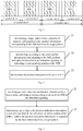
- the present disclosure provides a method of indicating an SSB, which is applicable to a base station side. As shown in Fig. 2 , the indicating method includes following step 21 to step 23.
- Step 21 determining a target pattern from a plurality of patterns and acquiring serial number information corresponding to the SSB based on the target pattern.
- Step 22 determining, according to the serial number information corresponding to the SSB, position indication information in an indication signaling for indicating a corresponding position of the SSB.
- Step 23 transmitting the position indication information to UE.
- the method of indicating an SSB By determining a target pattern from a plurality of patterns and acquiring serial number information corresponding to the SSB based on the target pattern, determining, according to the serial number information corresponding to the SSB, position indication information in an indication signaling for indicating a corresponding position of the SSB and transmitting the position indication information to a UE, the method of indicating an SSB provided by some embodiments of the present disclosure enables the UE to acquire the serial number information from the position indication information and determine the identifier of the pattern corresponding to the SSB and the position of the SSB in the pattern, thereby resolving the synchronization signal correctly for a subsequent operation, and, as a result, solving the problem in the related art that the determination and indication schemes for SSB cannot support a situation involving multiple patterns.
- the position indication information may be transmitted with six predetermined bits in the indication signaling.
- a step of determining, according to the serial number information corresponding to the SSB, the position indication information in the indication signaling for indicating the corresponding position of the SSB includes: determining the position indication information in the indication signaling for indicating the corresponding position of the SSB according to a position of the SSB in a pattern and an identifier of the pattern.
- a step of determining the position indication information in the indication signaling and for indicating the corresponding position of the SSB according to the position of the SSB in the pattern and the identifier of the pattern includes: determining a corresponding serial number of the SSB in the indication signaling according to a serial number of the SSB in the corresponding pattern and a serial number of the pattern.
- the identifier of the pattern may be the serial number of the pattern, or may be other information capable of characterizing the identity of the pattern, which is not limited herein.
- a step of transmitting the position indication information to the UE includes: transmitting the position indication information to the UE by means of PBCH and DMRS.
- the step of transmitting the position indication information to the UE includes: mapping a part of the position indication information onto a predetermined DMRS sequence according to the identifier of the pattern and transmitting the DMRS sequence.
- the part of the position indication information includes the serial number of a frequently used pattern, and the predetermined DMRS sequence may be an initially detected DMRS sequence.
- the method further includes: establishing a mapping relationship between the plurality of patterns and position indication information in the indication signaling according to priority information of the plurality of patterns.
- mapping relationship may be configured in advance, which is not limited herein.
- first SSBs always start from first symbols of respective slots, or always start from second symbols of respective slots, or some of the first SSBs start from first symbols of respective slots and the other of the first SSBs start from second symbols of respective slots.
- the abovementioned solutions may be applicable to base stations operating at sub-6 GHz.
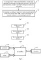
- some embodiments of the present disclosure further provide a method of determining an SSB, which is applicable to a UE side and includes following step 31 to step 32.
- Step 31 receiving position indication information in an indication signaling for indicating a corresponding position of the SSB, and the position indication information being transmitted by a base station.
- Step 32 determining, according to the position indication information, a slot and a position in the slot where an initial symbol of the SSB is located.
- the position indication information is acquired by the base station based on a target pattern.
- the method of determining an SSB By receiving position indication information in an indication signaling for indicating a corresponding position of the SSB, and the position indication information being transmitted by a base station; and determining, according to the position indication information, a slot and a position in the slot where an initial symbol of the SSB is located, the method of determining an SSB provided by some embodiments of the present disclosure analyzes the synchronization signal correctly for a subsequent operation, and, as a result, solves the problem in the related art that the determination and indication schemes for SSB cannot support a situation involving multiple patterns.
- a step of determining, according to the position indication information, the slot and the position in the slot where the initial symbol of the SSB is located includes: determining serial number information corresponding to the SSB according to the position indication information; and determining the slot and the position in the slot where the initial symbol of the SSB is located according to the serial number information.
- a step of receiving position indication information in an indication signaling for indicating a corresponding position of the SSB, and the position indication information being transmitted by a base station includes: receiving position indication information, transmitted by the base station, indicating a corresponding position of the SSB in an indication signaling by means of a synchronization detection and a PBCH detection.
- a step of determining the serial number information corresponding to the SSB according to the position indication information includes: determining an identifier of a pattern corresponding to the SSB and a position of the SSB in the pattern according to the position indication information.
- the identifier of the pattern may be the serial number of the pattern, or may be other information capable of characterizing the identity of the pattern, which is not limited herein.
- a step of determining the slot and the position in the slot where the initial symbol of the SSB is located according to the serial number information includes: determining the slot and the position in the slot where the initial symbol of the SSB is located according to the identifier of the pattern corresponding to the SSB and the position of the SSB in the pattern.
- a step of determining the identifier of the pattern corresponding to the SSB according to the position indication information includes: determining the identifier of the pattern corresponding to the SSB according to the position indication information and a mapping relationship between a pattern and position indication information for indicating a position in the indication signaling.
- mapping relationship may be configured in advance, which is not limited herein.
- the position indication information in the indication signaling for indicating the corresponding position of the SSB refers to a serial number of the SSB in the indication signaling
- the identifier of the pattern corresponding to the SSB refers to a serial number of the pattern corresponding to the SSB
- the position of the SSB in the pattern refers to a serial number of the SSB in the pattern.
- the abovementioned solutions may be applicable to UEs operating at a frequency smaller than 6 GHz.
- the solution provided by some embodiments of the present disclosure is mainly directed to the configuration and indication of a synchronization signal pattern in a beam scanning mode.
- each slot may consist of 14 symbols or 7 symbols.
- the SSB may start from symbol 1 of the slot, as shown in Fig. 4a , or start from symbol 2, as shown in Fig. 4b .
- the SSB pattern needs to be prescribed by a standard.
- UE should be informed of information about patterns employed.
- SSB When an NR system operates at sub-3 GHz, there are 4 SSBs in each synchronization period; when an NR system operates at a frequency from 3 GHz to 6 GHz, there are 8 SSBs in each synchronization period; and when a system operates at a frequency over 6 GHz, there are 64 SSBs in each synchronization period.
- the maximum serial number of SSB is 64, and the system should be able to indicate 64 SSBs.
- the serial number of SSB is indicated by PBCH and DMRS.
- the SSB serial number information is partially or totally indicated by bit-mapping, which is called explicit indication.
- the serial number of SSB is indicated by using DMRS
- DMRS sequences corresponding to different SSB serial numbers are different from each other
- the 8 DMRS sequences require three bits of indicated information, which is called implicit indication.
- the explicit and implicit indication may jointly indicate 6 bits of information.
- an SSB serial number indication capability of a system is 6-bit.
- the following description is mainly directed to methods for indicating an SSB pattern and determining an SSB pattern, and the content carried by the indication signaling/reference signal with respect to SSB serial number.
- the NR system When an NR system operates at sub-6 GHz, the NR system supports a slot of 14 symbols or a slot of 7 symbols.
- the symbol 0 is reserved for a downlink (DL) control symbol
- the symbol 5 and symbol 6 are reserved for a gap and uplink (UL) transmission, in this way, only the middle 4 symbols may be used for SSB transmission.
- the system may reserve multiple symbols at an initial position of a slot for DL control, which may enhance the flexibility in scheduling of a self-contained subframe.
- the self-contained subframe is a frame structure proposed to reduce latency, and a detailed description thereof is omitted.
- the system has a 6-bit indication capability for SSB serial numbers.
- one synchronization period has only 8 SSBs, which requires only an indication capacity of 3 bits, as a result, the system has an additional available capacity of 3 bits; and when the system operates at a frequency from 0 GHz to 3 GHz, one synchronization period has only 4 SSBs, which requires only an indication capacity of 2 bits, as a result, the system has an additional available capacity of 4 bits.
- the solutions provided by some embodiments of the present disclosure mainly use the additional available capacity to indicate serial numbers of SSBs in the pattern.
- the M SSBs of pattern 1 correspond to 0 to M-1 of the explicit and implicit SSB indication signaling
- the M SSBs of pattern 2 correspond to M to 2M-1 of the explicit and implicit SSB indication signaling, and so on.
- DMRS is used for the indication, a serial number of frequently used pattern is mapped to initially detected DMRS sequence to reduce the occurrence of blind detection.
- SSB is transmitted according to following operations. (1) determining a serial number of each SSB in the indication signaling.
- the serial number of SSB in the indication signaling includes two portions: one is the SSB serial number of the SSB in a current period, and the other is the serial number of the pattern to which the SSB belongs.
- 8 SSBs of pattern 1 correspond to 0 to 7 of the explicit and implicit SSB indication signaling
- 8 SSBs of pattern 2 correspond to 8 to 15 of the explicit and implicit SSB indication signaling.
- pattern 1 is as shown in Fig. 5
- pattern 2 is as shown in Fig. 4b .
- 8 SSBs of pattern 1 correspond to 0 to 7 of the explicit and implicit SSB indication signaling
- 8 SSBs of pattern 2 correspond to 8 to 15 of the explicit and implicit SSB indication signaling
- ... and 8 SSBs of pattern N correspond to 8N-8 to 8N-1 of the explicit and implicit SSB indication signaling, where N>2.
- 4 SSBs of pattern 1 correspond to 0 to 3 of the explicit and implicit SSB indication signaling
- 4 SSBs of pattern 2 correspond to 4 to 7 of the explicit and implicit SSB indication signaling
- SSB is detected according to following operations.
- the pattern serial number of SSB is y, the serial number of SSB is x, then the location of an initial symbol of the z-th SSB in the y-th pattern is a desired value (absolute position of SSB).
- an SSB pattern is indicated by using existing bits in the system, thereby enhancing the flexibility of system without incurring additional overhead.
- some embodiments of the present disclosure further provide a method of indicating an SSB.
- the method is applicable to a base station side and includes step 61 and step 62.
- Step 61 determining, according to an SSB serial number of the SSB in a current period and slot structure information corresponding to the SSB, position indication information in an indication signaling for indicating a corresponding position of the SSB.
- Step 62 transmitting the position indication information to a user equipment.
- the method of indicating an SSB By determining, according to an SSB serial number of the SSB in a current period and slot structure information corresponding to the SSB, position indication information in an indication signaling for indicating a corresponding position of the SSB, and transmitting the position indication information to UE, the method of indicating an SSB provided by some embodiments of the present disclosure achieves the objective of utilizing the surplus bits of the indication signaling of SSB serial number to indicate frame structure information of the system, such that the UE may be provided with the frame structure information without adding a signaling specialized in indicating the frame structure, thereby conserving resources.
- a step of transmitting the position indication information to UE includes: transmitting the position indication information to the UE by means of PBCH and DMRS.
- the slot structure information indicates that a slot structure currently used by a base station is a 7-symbol slot structure or a 14-symbol slot structure.
- the method before determining, according to an SSB serial number of the SSB in a current period and slot structure information corresponding to the SSB, position indication information in an indication signaling for indicating a corresponding position of the SSB, the method further includes: establishing a mapping relationship between slot structures and position indication information for indicating a position in the indication signaling.
- the mapping relationship may be configured in advance, which is not limited herein.
- the abovementioned solution may be applicable to a base station operating at sub-6 GHz.
- the solution provided by some embodiments of the present disclosure effectively solves the problem of a waste of resources caused by that a specialized signaling is needed to indicate a system frame structure.
- some embodiments of the present disclosure further provide a method of determining an SSB.
- the determining method may be applicable to a UE side and includes step 71 and step 72.
- Step 71 receiving position indication information in an indication signaling for indicating a corresponding position of the SSB, and the position indication information being transmitted by a base station.
- Step 72 determining, according to the position indication information, an SSB serial number of the SSB in a current period and slot structure information corresponding to the SSB.
- the method of determining an SSB is capable of acquiring the SSB serial number of the SSB in a current period and the slot structure information corresponding to the SSB simultaneously without acquiring the frame structure information by means of a specialized signaling, thus achieving the objective of utilizing the surplus bits of the indication signaling of SSB serial number to indicate frame structure information of the system and thereby conserving resources.
- a step of receiving position indication information in an indication signaling for indicating a corresponding position of the SSB, and the position indication information being transmitted by a base station includes: receiving position indication information, transmitted by the base station, indicating a corresponding position of the SSB in an indication signaling by means of a synchronization detection and a PBCH detection.
- a step of determining, according to the position indication information, slot structure information corresponding to the SSB includes: determining the slot structure information corresponding to the SSB according to the position indication information and a mapping relationship between a slot structure and position indication information for indicating a position in the indication signaling.
- the method further includes: configuring the mapping relationship in advance.
- the position indication information in the indication signaling for indicating the corresponding position of the SSB includes a serial number of the SSB in the indication signaling, and the slot structure information corresponding to the SSB indicates that a slot structure currently used by the base station is a 7-symbol slot structure or a 14-symbol slot structure.
- the abovementioned solution is applicable to UE operating at sub-6 GHz.
- a second method of indicating an SSB applicable to a base station side and a second method of determining an SSB applicable to a UE side are described in detail hereinafter.
- SSB is transmitted according to following operations. (1) determining a serial number of each SSB in the indication signaling.
- the serial number of SSB in the indication signaling includes two portions: one is the SSB serial number of the SSB in a current period, and the other is the system slot structure is 7-symbol slot or 14-symbol slot.
- 8 SSBs of a 14-symbol slot structure correspond to 0 to 7 of the explicit and implicit SSB indication signaling
- 8 SSBs of a 7-symbol slot structure correspond to 8 to 15 of the explicit and implicit SSB indication signaling.
- SSB is detected according to following operations.
- the serial number of SSB in the indication signaling that is detected by UE is x
- the solution provided by some embodiments of the present disclosure dispenses with the need for an additional specialized signaling to indicate frame structure, thereby conserving resources.
- some embodiments of the present disclosure further provide an apparatus of indicating an SSB.
- the apparatus may be applied to a base station side and include: a first processing module 81, configured to determine a target pattern from a plurality of patterns and acquire serial number information corresponding to the SSB based on the target pattern; a first determination module 82, configured to determine, according to the serial number information corresponding to the SSB, position indication information in an indication signaling for indicating a corresponding position of the SSB; and a first transmission module 83, configured to transmit the position indication information to UE.
- the apparatus of indicating an SSB By determining a target pattern from a plurality of patterns and acquiring serial number information corresponding to the SSB based on the target pattern, determining, according to the serial number information corresponding to the SSB, position indication information in an indication signaling for indicating a corresponding position of the SSB and transmitting the position indication information to UE, the apparatus of indicating an SSB provided by some embodiments of the present disclosure enables UE to acquire the serial number information from the position indication information and determine the identifier of the pattern corresponding to the SSB and the position of the SSB in the pattern, thereby resolving the synchronization signal correctly for a subsequent operation, and, as a result, solving the problem in the related art that the determination and indication schemes for SSB cannot support a situation involving multiple patterns.
- the first determination module includes: a first determination sub-module, configured to determine the position indication information in the indication signaling for indicating the corresponding position of the SSB according to a position of the SSB in a pattern and an identifier of the pattern.
- the first determination sub-module includes: a first determination unit, configured to determine a corresponding serial number of the SSB in the indication signaling according to a serial number of the SSB in the pattern and a serial number of the pattern.
- the first transmission module includes: a first transmission sub-module, configured to map a part of the position indication information onto a predetermined DMRS sequence according to the identifier of the pattern and transmit the DMRS sequence.
- the apparatus further includes: a first establishment module, configured to, before the position indication information in the indication signaling for indicating the corresponding position of the SSB is determined according to the serial number information corresponding to the SSB, establish a mapping relationship between the plurality of patterns and position indication information in the indication signaling according to priority information of the plurality of patterns.
- a first establishment module configured to, before the position indication information in the indication signaling for indicating the corresponding position of the SSB is determined according to the serial number information corresponding to the SSB, establish a mapping relationship between the plurality of patterns and position indication information in the indication signaling according to priority information of the plurality of patterns.
- first SSBs always start from first symbols of respective slots, or always start from second symbols of respective slots, or some of the first SSBs start from first symbols of respective slots and the other of the first SSBs start from second symbols of respective slots.
- the abovementioned solution may be applied to a base station operating at sub-6 GHz.
- the embodiments of the first method of indicating an SSB applied to a base station side are all applicable to the embodiments of the apparatus of indicating an SSB and may achieve the same technical effects.
- Some embodiments of the present disclosure further provide a base station, including: a storage, a processor and a computer program stored on the storage and executable by the processor, where when executing the program, the processor is configured to perform following steps: determining a target pattern from a plurality of patterns and acquiring serial number information corresponding to the SSB based on the target pattern; determining, according to the serial number information corresponding to the SSB, position indication information in an indication signaling for indicating a corresponding position of the SSB; and transmitting the position indication information to UE by means of a transceiver.
- the base station By determining a target pattern from a plurality of patterns and acquiring serial number information corresponding to the SSB based on the target pattern, determining, according to the serial number information corresponding to the SSB, position indication information in an indication signaling for indicating a corresponding position of the SSB and transmitting the position indication information to UE, the base station provided by some embodiments of the present disclosure enables UE to acquire the serial number information from the position indication information and determine the identifier of the pattern corresponding to the SSB and the position of the SSB in the pattern, thereby resolving the synchronization signal correctly for a subsequent operation, and, as a result, solving the problem in the related art that the determination and indication schemes for SSB cannot support a situation involving multiple patterns.
- the base station provided by some embodiments of the present disclosure includes: a processor 91, and a storage 93 connected to the processor 91 via a bus interface 92, the storage 93 is configured to store program and data used by the processor 91 in operation, the processor 91 is configured to call and execute the program and data stored in the storage 93 to implement the following process: determining a target pattern from a plurality of patterns and acquiring serial number information corresponding to the SSB based on the target pattern; and transmitting the position indication information to UE by means of a transceiver 94.
- the transceiver 94 is connected to the bus interface 92 and configured to receive and transmit data under the control of the processor 91.
- a bus architecture may include any quantity of interconnected buses and bridges, such that various circuits including one or more processors represented by the processor 91 and storages represented by the storage 93 are connected to each other.
- the bus architecture may also connect various other circuits such as peripherals, voltage regulators and power management circuits, which is well known in the art. Therefore, a detailed description thereof is omitted herein.
- Bus interface provides an interface.
- the transceiver 94 may include multiple elements, such as a receiver and a transmitter, to allow for communication with various other apparatuses on the transmission medium.
- the processor 91 is responsible for supervising the bus architecture and normal operation and the storage 93 may store the data currently used by the processor 91 during operation.
- all or a part of steps of the foregoing embodiments may be implemented by hardware, or implemented by associated hardware under the control of a computer program.
- the computer program includes instructions configured to perform a part or all of the steps of the foregoing method, and may be stored in a readable storage medium, which may be any form of storage medium, such as a volatile or non-volatile computer readable storage medium, a transient or non-transient computer readable storage medium.
- the processor is configured to: determine the position indication information in the indication signaling for indicating the corresponding position of the SSB according to a position of the SSB in a pattern and an identifier of the pattern. More specifically, the processor is configured to: determine a corresponding serial number of the SSB in the indication signaling according to a serial number of the SSB in the pattern and a serial number of the pattern.
- the processor is configured to: transmit the position indication information to the UE by means of PBCH and DMRS.
- the processor is configured to: map a part of the position indication information onto a predetermined DMRS sequence according to the identifier of the pattern and transmit the DMRS sequence.
- the processor is configured to: before determining, according to the serial number information corresponding to the SSB, the position indication information in the indication signaling for indicating the corresponding position of the SSB, establish a mapping relationship between the plurality of patterns and position indication information in the indication signaling according to priority information of the plurality of patterns.
- first SSBs always start from first symbols of respective slots, or always start from second symbols of respective slots, or some of the first SSBs start from first symbols of respective slots and the other of the first SSBs start from second symbols of respective slots.
- the foregoing base station may be a base station operating at sub-6 GHz.
- the embodiments of the first method of indicating an SSB applied to a base station side are all applicable to the embodiments of the base station and may achieve the same technical effects.
- Some embodiments of the present disclosure further provide a computer readable storage medium storing thereon a computer program, where the computer program is configured to be executed by a processor to implement following steps: determining a target pattern from a plurality of patterns and acquiring serial number information corresponding to the SSB based on the target pattern; determining, according to the serial number information corresponding to the SSB, position indication information indicating a corresponding position of the SSB in an indication signaling; transmitting the position indication information to UE.
- the computer readable storage medium By determining a target pattern from a plurality of patterns and acquiring serial number information corresponding to the SSB based on the target pattern, determining, according to the serial number information corresponding to the SSB, position indication information in an indication signaling for indicating a corresponding position of the SSB and transmitting the position indication information to UE, the computer readable storage medium provided by some embodiments of the present disclosure enables UE to acquire the serial number information from the position indication information and determine the identifier of the pattern corresponding to the SSB and the position of the SSB in the pattern, thereby resolving the synchronization signal correctly for a subsequent operation, and, as a result, solving the problem in the related art that the determination and indication schemes for SSB cannot support a situation involving multiple patterns.
- determining, according to the serial number information corresponding to the SSB, the position indication information in the indication signaling for indicating the corresponding position of the SSB includes: determining the position indication information in the indication signaling for indicating the corresponding position of the SSB according to a position of the SSB in a pattern and an identifier of the pattern. More specifically, determining the position indication information in the indication signaling for indicating the corresponding position of the SSB according to the position of the SSB in the pattern and the identifier of the pattern includes: determining a corresponding serial number of the SSB in the indication signaling according to a serial number of the SSB in the pattern and a serial number of the pattern.
- a step of transmitting the position indication information to the UE includes: transmitting the position indication information to the UE by means of PBCH and DMRS.
- the step of transmitting the position indication information to the UE includes: mapping a part of the position indication information onto a predetermined DMRS sequence according to the identifier of the pattern and transmitting the DMRS sequence.
- the computer program is configured to be executed by a processor to implement following step: before determining, according to the serial number information corresponding to the SSB, the position indication information in the indication signaling for indicating the corresponding position of the SSB, establishing a mapping relationship between the plurality of patterns and position indication information in the indication signaling according to priority information of the plurality of patterns.
- first SSBs always start from first symbols of respective slots, or always start from second symbols of respective slots, or some of the first SSBs start from first symbols of respective slots and the other start from second symbols of respective slots.
- the abovementioned solution is applicable to a base station operating at sub-6 GHz.
- the embodiments of the first method of indicating an SSB applied to a base station side are all applicable to the embodiments of the computer readable storage medium and may achieve the same technical effects.
- some embodiments of the present disclosure further provide an apparatus of determining an SSB.
- the apparatus is applicable to a UE side and includes: a first reception module 101, configured to receive position indication information in an indication signaling for indicating a corresponding position of the SSB, and the position indication information being transmitted by a base station; and a second determination module 102, configured to determine, according to the position indication information, a slot and a position in the slot where an initial symbol of the SSB is located; where the position indication information is acquired by the base station based on a target pattern.
- the apparatus of determining an SSB By receiving position indication information in an indication signaling for indicating a corresponding position of the SSB, and the position indication information being transmitted by a base station; and determining, according to the position indication information, a slot and a position in the slot where an initial symbol of the SSB is located, the apparatus of determining an SSB provided by some embodiments of the present disclosure resolves the synchronization signal correctly for a subsequent operation, and, as a result, solves the problem in the related art that the determination and indication schemes for SSB cannot support a situation involving multiple patterns.
- the second determination module includes: a second determination sub-module, configured to determine serial number information corresponding to the SSB according to the position indication information; and a third determination sub-module, configured to determine the slot and the position in the slot where the initial symbol of the SSB is located according to the serial number information.
- the second determination sub-module includes: a second determination unit, configured to determine an identifier of a pattern corresponding to the SSB and a position of the SSB in the pattern according to the position indication information.
- the third determination sub-module includes: a third determination unit, configured to determine the slot and the position in the slot where the initial symbol of the SSB is located according to the identifier of the pattern corresponding to the SSB and the position of the SSB in the pattern.
- the position indication information in the indication signaling for indicating the corresponding position of the SSB includes a serial number of the SSB in the indication signaling
- the identifier of the pattern corresponding to the SSB includes a serial number of the pattern corresponding to the SSB
- the position of the SSB in the pattern includes a serial number of the SSB in the pattern.
- the abovementioned solution is applicable to UE operating at sub-6 GHz.
- the embodiments of the first method of determining an SSB applied to a UE side are all applicable to the embodiments of the apparatus of determining an SSB and may achieve the same technical effects.
- Some embodiments of the present disclosure further provide UE, including: a storage, a processor and a computer program stored on the storage and executable by the processor, where when executing the program, the processor is configured to perform following steps: receiving, by a transceiver, position indication information in an indication signaling for indicating a corresponding position of the SSB, and the position indication information being transmitted by a base station; and determining, according to the position indication information, a slot and a position in the slot where an initial symbol of the SSB is located; where the position indication information is acquired by the base station based on a target pattern.
- the UE By receiving position indication information in an indication signaling for indicating a corresponding position of the SSB, and the position indication information being transmitted by a base station; and determining, according to the position indication information, a slot and a position in the slot where an initial symbol of the SSB is located, the UE provided by some embodiments of the present disclosure resolves the synchronization signal correctly for a subsequent operation, and, as a result, solves the problem in the related art that the determination and indication schemes for SSB cannot support a situation involving multiple patterns.
- the UE provided by some embodiments of the present disclosure includes: a processor 111, and a storage 113 connected to the processor 111 via a bus interface 112, the storage 113 is configured to store program and data used by the processor 111 in operation, the processor 111 is configured to call and execute the program and data stored in the storage 113 to implement the following process: receiving, by a transceiver 114, position indication information in an indication signaling for indicating a corresponding position of the SSB, and the position indication information being transmitted by a base station; and determining, according to the position indication information, a slot and a position in the slot where an initial symbol of the SSB is located.
- the transceiver 114 is connected to the bus interface 112 and configured to receive and transmit data under the control of the processor 111.
- a bus architecture may include any quantity of interconnected buses and bridges, such that various circuits including one or more processors represented by the processor 111 and storages represented by the storage 113 are connected to each other.
- the bus architecture may also connect various other circuits such as peripherals, voltage regulators and power management circuits, which is well known in the art. Therefore, a detailed description thereof is omitted herein.
- Bus interface provides an interface.
- the transceiver 114 may include multiple elements, such as a receiver and a transmitter, to allow for communication with various other apparatuses on the transmission medium.
- user interface 115 may be an interface configured to connect to a requisite device externally or internally, and the connected device includes, but not limited to: a keypad, display, speaker, microphone, joystick, etc.
- the processor 111 is responsible for supervising the bus architecture and normal operation and the storage 113 may store the data currently used by the processor 111 during operation.
- all or a part of steps of the foregoing embodiments may be implemented by hardware, or implemented by associated hardware under the control of a computer program.
- the computer program includes instructions configured to perform a part or all of the steps of the foregoing method, and may be stored in a readable storage medium, which may be any form of storage medium, such as a volatile or non-volatile computer readable storage medium, a transient or non-transient computer readable storage medium.
- the processor is configured to: determine serial number information corresponding to the SSB according to the position indication information; and determine the slot and the position in the slot where the initial symbol of the SSB is located according to the serial number information.
- the processor is specifically configured to: receive position indication information in an indication signaling, transmitted by the base station, indicating a corresponding position of the SSB by means of a synchronization detection and a PBCH detection.
- the processor is specifically configured to: determine an identifier of a pattern corresponding to the SSB and a position of the SSB in the pattern according to the position indication information.
- the processor is specifically configured to: determine the slot and the position in the slot where the initial symbol of the SSB is located according to the identifier of the pattern corresponding to the SSB and the position of the SSB in the pattern.
- the processor is specifically configured to: determine the identifier of the pattern corresponding to the SSB according to the position indication information and a mapping relationship between a pattern and position indication information for indicating a position in the indication signaling.
- the position indication information in the indication signaling for indicating the corresponding position of the SSB includes a serial number of the SSB in the indication signaling
- the identifier of the pattern corresponding to the SSB includes a serial number of the pattern corresponding to the SSB
- the position of the SSB in the pattern includes a serial number of the SSB in the pattern.
- the abovementioned UE may be UE operating at sub-6 GHz.
- the embodiments of the first method of determining an SSB applied to a UE side are all applicable to the embodiments of the UE and may achieve the same technical effects. It can be seen from above, the foregoing solution provided by some embodiments of the present disclosure solves the problem in the related art that the determination and indication schemes for SSB cannot support a situation involving multiple patterns.
- Some embodiments of the present disclosure further provide a computer readable storage medium storing thereon a computer program, where the computer program is configured to be executed by a processor to implement following steps: receiving position indication information in an indication signaling, transmitted by a base station, indicating a corresponding position of the SSB; determining, according to the position indication information, a slot and a position in the slot where an initial symbol of the SSB is located.
- the position indication information is acquired by the base station based on a target pattern.
- the computer readable storage medium By receiving position indication information in an indication signaling, transmitted by a base station, indicating a corresponding position of the SSB; and determining, according to the position indication information, a slot and a position in the slot where an initial symbol of the SSB is located, the computer readable storage medium provided by some embodiments of the present disclosure resolves the synchronization signal correctly for a subsequent operation, and, as a result, solves the problem in the related art that the determination and indication schemes for SSB cannot support a situation involving multiple patterns.
- a step of determining, according to the position indication information, the slot and the position in the slot where the initial symbol of the SSB is located includes: determining serial number information corresponding to the SSB according to the position indication information; and determining the slot and the position in the slot where the initial symbol of the SSB is located according to the serial number information.
- a step of receiving position indication information in an indication signaling, transmitted by the base station, indicating a corresponding position of the SSB includes: receiving position indication information, transmitted by the base station, indicating a corresponding position of the SSB in an indication signaling by means of a synchronization detection and a PBCH detection.
- a step of determining the serial number information corresponding to the SSB according to the position indication information includes: determining an identifier of a pattern corresponding to the SSB and a position of the SSB in the pattern according to the position indication information.
- a step of determining the slot and the position in the slot where the initial symbol of the SSB is located according to the serial number information includes: determining the slot and the position in the slot where the initial symbol of the SSB is located according to the identifier of the pattern corresponding to the SSB and the position of the SSB in the pattern.
- determining the identifier of the pattern corresponding to the SSB according to the position indication information includes: determining the identifier of the pattern corresponding to the SSB according to the position indication information and a mapping relationship between a pattern and position indication information for indicating a position in the indication signaling.
- the position indication information in the indication signaling for indicating the corresponding position of the SSB includes a serial number of the SSB in the indication signaling
- the identifier of the pattern corresponding to the SSB includes a serial number of the pattern corresponding to the SSB
- the position of the SSB in the pattern comprises a serial number of the SSB in the pattern.
- the abovementioned solution is applicable to UE operating at sub-6 GHz.
- the embodiments of the first method of determining an SSB applied to a UE side are all applicable to the embodiments of the computer readable storage medium and may achieve the same technical effects.
- some embodiments of the present disclosure further provide an apparatus of indicating an SSB.
- the apparatus is applicable to a base station side and includes: a third determination module 121, configured to determine, according to an SSB serial number of the SSB in a current period and slot structure information corresponding to the SSB, position indication information in an indication signaling for indicating a corresponding position of the SSB; and a second transmission module 122, configured to transmit the position indication information to UE.
- the apparatus of indicating an SSB By determining, according to an SSB serial number of the SSB in a current period and slot structure information corresponding to the SSB, position indication information in an indication signaling for indicating a corresponding position of the SSB and transmitting the position indication information to UE, the apparatus of indicating an SSB provided by some embodiments of the present disclosure achieves the objective of utilizing the surplus bits of the indication signaling of SSB serial number to indicate frame structure information of the system, such that the UE may be provided with the frame structure information without adding a signaling specialized in indicating the frame structure, thereby conserving resources.
- the slot structure information indicates that a slot structure currently used by a base station is a 7-symbol slot structure or a 14-symbol slot structure.
- the abovementioned solution is applicable to a base station operating at sub-6 GHz.
- the embodiments of the second method of indicating an SSB applied to a base station side are all applicable to the embodiments of the apparatus of indicating an SSB and may achieve the same technical effects.
- the solution provided by some embodiments of the present disclosure solves the problem that a specialized signaling is needed to indicate system frame structure, thereby wasting resources.
- Some embodiments of the present disclosure further provide a base station, including: a storage, a processor and a computer program stored on the storage and executable by the processor, where when executing the program, the processor is configured to perform following steps: determining, according to an SSB serial number of the SSB in a current period and slot structure information corresponding to the SSB, position indication information in an indication signaling for indicating a corresponding position of the SSB; and transmitting the position indication information to UE by means of a transceiver.
- the base station By determining, according to an SSB serial number of the SSB in a current period and slot structure information corresponding to the SSB, position indication information in an indication signaling for indicating a corresponding position of the SSB and transmitting the position indication information to UE, the base station provided by some embodiments of the present disclosure achieves the objective of utilizing the surplus bits of the indication signaling of SSB serial number to indicate frame structure information of the system, such that the UE may be provided with the frame structure information without adding a signaling specialized in indicating the frame structure, thereby conserving resources.
- the base station provided by some embodiments of the present disclosure includes: a processor 131, and a storage 133 connected to the processor 131 via a bus interface 132, the storage 133 is configured to store program and data used by the processor 131 in operation, the processor 131 is configured to call and execute the program and data stored in the storage 133 to implement the following process: determining, according to an SSB serial number of the SSB in a current period and slot structure information corresponding to the SSB, position indication information in an indication signaling for indicating a corresponding position of the SSB; and transmitting the position indication information to UE by means of a transceiver 134.
- the transceiver 134 is connected to the bus interface 132 and configured to receive and transmit data under the control of the processor 131.
- a bus architecture may include any quantity of interconnected buses and bridges, such that various circuits including one or more processors represented by the processor 131 and storages represented by the storage 133 are connected to each other.
- the bus architecture may also connect various other circuits such as peripherals, voltage regulators and power management circuits, which is well known in the art. Therefore, a detailed description thereof is omitted herein.
- Bus interface provides an interface.
- the transceiver 134 may include multiple elements, such as a receiver and a transmitter, to allow for communication with various other apparatuses on the transmission medium.
- the processor 131 is responsible for supervising the bus architecture and normal operation and the storage 133 may store the data currently used by the processor 131 during operation.
- all or a part of steps of the foregoing embodiments may be implemented by hardware, or implemented by associated hardware under the control of a computer program.
- the computer program includes instructions configured to perform a part or all of the steps of the foregoing method, and may be stored in a readable storage medium, which may be any form of storage medium, such as a volatile or non-volatile computer readable storage medium, a transient or non-transient computer readable storage medium.
- the processor is specifically configured to: transmit the position indication information to the UE by means of PBCH and DMRS.
- the slot structure information indicates that a slot structure currently used by a base station is a 7-symbol slot structure or a 14-symbol slot structure.
- the abovementioned base station may be a base station operating at sub-6 GHz.
- the embodiments of the second method of indicating an SSB applied to a base station side are all applicable to the embodiments of the base station and may achieve the same technical effects.
- the solution provided by some embodiments of the present disclosure effectively solves the problem of a waste of resources caused by that a specialized signaling is needed to indicate a system frame structure.
- Some embodiments of the present disclosure further provide a computer readable storage medium storing thereon a computer program, where the computer program is configured to be executed by a processor to implement following steps: determining, according to an SSB serial number of the SSB in a current period and slot structure information corresponding to the SSB, position indication information in an indication signaling for indicating a corresponding position of the SSB; and transmitting the position indication information to UE.
- the computer readable storage medium By determining, according to an SSB serial number of the SSB in a current period and slot structure information corresponding to the SSB, position indication information in an indication signaling for indicating a corresponding position of the SSB and transmitting the position indication information to UE, the computer readable storage medium provided by some embodiments of the present disclosure achieves the objective of utilizing the surplus bits of the indication signaling of SSB serial number to indicate frame structure information of the system, such that the UE may be provided with the frame structure information without adding a signaling specialized in indicating the frame structure, thereby conserving resources.
- a step of transmitting the position indication information to UE includes: transmitting the position indication information to the UE by means of PBCH and DMRS.
- the slot structure information indicates that a slot structure currently used by a base station is a 7-symbol slot structure or a 14-symbol slot structure.
- the abovementioned solution is applicable to a base station operating at sub-6 GHz.
- the embodiments of the second method of indicating an SSB applied to a base station side are all applicable to the embodiments of the computer readable storage medium and may achieve the same technical effects.
- the solution provided by some embodiments of the present disclosure solves the problem that a specialized signaling is needed to indicate system frame structure, thereby wasting resources.
- some embodiments of the present disclosure further provide an apparatus of determining an SSB.
- the apparatus is applicable to a UE side and includes: a second reception module 141, configured to receive position indication information in an indication signaling, transmitted by a base station, indicating a corresponding position of the SSB; and a fourth determination module 142, configured to determine, according to the position indication information, an SSB serial number of the SSB in a current period and slot structure information corresponding to the SSB.
- the apparatus of determining an SSB is capable of acquiring the SSB serial number of the SSB in a current period and the slot structure information corresponding to the SSB simultaneously without acquiring the frame structure information by means of a specialized signaling, thus achieving the objective of utilizing the surplus bits of the indication signaling of SSB serial number to indicate frame structure information of the system and thereby conserving resources.
- the fourth determination module includes: a fourth determination sub-module, configured to determine the slot structure information corresponding to the SSB according to the position indication information and a mapping relationship between a slot structure and position indication information for indicating a position in the indication signaling.
- the position indication information in the indication signaling for indicating the corresponding position of the SSB includes a serial number of the SSB in the indication signaling, and the slot structure information corresponding to the SSB indicates that a slot structure currently used by the base station is a 7-symbol slot structure or a 14-symbol slot structure.
- the abovementioned solution is applicable to UE operating at sub-6 GHz.
- the embodiments of the second method of determining an SSB applied to a UE side are all applicable to the embodiments of the apparatus of determining an SSB and may achieve the same technical effects.
- the solution provided by some embodiments of the present disclosure solves the problem that a specialized signaling is needed to indicate system frame structure, thereby wasting resources.
- Some embodiments of the present disclosure further provide UE, including: a storage, a processor and a computer program stored on the storage and executable by the processor, where when executing the program, the processor is configured to perform following steps: receiving position indication information in an indication signaling, transmitted by a base station, indicating a corresponding position of the SSB by means of a transceiver; and determining, according to the position indication information, an SSB serial number of the SSB in a current period and slot structure information corresponding to the SSB.
- the UE By receiving position indication information in an indication signaling, transmitted by a base station, indicating a corresponding position of the SSB; and determining, according to the position indication information, an SSB serial number of the SSB in a current period and slot structure information corresponding to the SSB, the UE provided by some embodiments of the present disclosure is capable of acquiring the SSB serial number of the SSB in a current period and the slot structure information corresponding to the SSB simultaneously without acquiring the frame structure information by means of a specialized signaling, thus achieving the objective of utilizing the surplus bits of the indication signaling of SSB serial number to indicate frame structure information of the system and thereby conserving resources.
- the UE provided by some embodiments of the present disclosure includes: a processor 151, and a storage 153 connected to the processor 151 via a bus interface 152, the storage 153 is configured to store program and data used by the processor 151 in operation, the processor 151 is configured to call and execute the program and data stored in the storage 153 to implement the following process: receiving position indication information in an indication signaling, transmitted by a base station, indicating a corresponding position of the SSB by means of a transceiver 154; and determining, according to the position indication information, an SSB serial number of the SSB in a current period and slot structure information corresponding to the SSB.
- the transceiver 154 is connected to the bus interface 152 and configured to receive and transmit data under the control of the processor 151.
- a bus architecture may include any quantity of interconnected buses and bridges, such that various circuits including one or more processors represented by the processor 151 and storages represented by the storage 153 are connected to each other.
- the bus architecture may also connect various other circuits such as peripherals, voltage regulators and power management circuits, which is well known in the art. Therefore, a detailed description thereof is omitted herein.
- Bus interface provides an interface.
- the transceiver 154 may include multiple elements, such as a receiver and a transmitter, to allow for communication with various other apparatuses on the transmission medium.
- user interface 155 may be an interface configured to connect to a requisite device externally or internally, and the connected device includes, but not limited to: a keypad, display, speaker, microphone, joystick, etc.
- the processor 151 is responsible for supervising the bus architecture and normal operation and the storage 153 may store the data currently used by the processor 151 during operation.
- all or a part of steps of the foregoing embodiments may be implemented by hardware, or implemented by associated hardware under the control of a computer program.
- the computer program includes instructions configured to perform a part or all of the steps of the foregoing method, and may be stored in a readable storage medium, which may be any form of storage medium, such as a volatile or non-volatile computer readable storage medium, a transient or non-transient computer readable storage medium.
- the processor is specifically configured to: receive position indication information in an indication signaling, transmitted by the base station, indicating a corresponding position of the SSB by means of a synchronization detection and a PBCH detection.
- the processor is configured to: determine the slot structure information corresponding to the SSB according to the position indication information and a mapping relationship between a slot structure and position indication information for indicating a position in the indication signaling.
- the position indication information in the indication signaling for indicating the corresponding position of the SSB includes a serial number of the SSB in the indication signaling, and the slot structure information corresponding to the SSB indicates that a slot structure currently used by the base station is a 7-symbol slot structure or a 14-symbol slot structure.
- the abovementioned UE may be UE operating at sub-6 GHz.
- the embodiments of the second method of determining an SSB applied to a UE side are all applicable to the embodiments of the UE and may achieve the same technical effects.
- the solution provided by some embodiments of the present disclosure solves the problem that a specialized signaling is needed to indicate system frame structure, thereby wasting resources.
- Some embodiments of the present disclosure further provide a computer readable storage medium storing thereon a computer program, where the computer program is configured to be executed by a processor to implement following steps: receiving position indication information in an indication signaling, transmitted by a base station, indicating a corresponding position of the SSB; and determining, according to the position indication information, an SSB serial number of the SSB in a current period and slot structure information corresponding to the SSB.
- the computer readable storage medium By receiving position indication information in an indication signaling, transmitted by a base station, indicating a corresponding position of the SSB; and determining, according to the position indication information, an SSB serial number of the SSB in a current period and slot structure information corresponding to the SSB, the computer readable storage medium provided by some embodiments of the present disclosure is capable of acquiring the SSB serial number of the SSB in a current period and the slot structure information corresponding to the SSB simultaneously without acquiring the frame structure information by means of a specialized signaling, thus achieving the objective of utilizing the surplus bits of the indication signaling of SSB serial number to indicate frame structure information of the system and thereby conserving resources.
- a step of receiving position indication information in an indication signaling, transmitted by a base station, indicating a corresponding position of the SSB includes: receiving position indication information, transmitted by the base station, indicating a corresponding position of the SSB in an indication signaling by means of a synchronization detection and a PBCH detection.
- a step of determining, according to the position indication information, a slot structure information corresponding to the SSB includes: determining the slot structure information corresponding to the SSB according to the position indication information and a mapping relationship between a slot structure and position indication information for indicating a position in the indication signaling.
- the position indication information in the indication signaling for indicating the corresponding position of the SSB includes a serial number of the SSB in the indication signaling, and the slot structure information corresponding to the SSB indicates that a slot structure currently used by the base station is a 7-symbol slot structure or a 14-symbol slot structure.
- the abovementioned solution is applicable to UE operating at sub-6 GHz.
- the embodiments of the second method of determining an SSB applied to a UE side are all applicable to the embodiments of the computer readable storage medium and may achieve the same technical effects.
- the solution provided by some embodiments of the present disclosure solves the problem that a specialized signaling is needed to indicate system frame structure, thereby wasting resources.
- module/sub-module/unit many functional components described in this specification are referred to as module/sub-module/unit, so as to emphasize the independence of its implementation more expressly.
- the module/sub-module/unit may be implemented in software, so as to be executed by various types of processors.
- an identified executable code module may include one or more physical or logical blocks of computer instructions, e.g., implemented as an object, process or function. Nevertheless, it is unnecessary for executable codes of the identified module to be located at the same place physically, instead, the identified module may include different instructions stored at different positions. When the instructions are combined logically, the instructions constitute a module and achieve the stipulated purpose of the module.
- the executable code module may include one or more instructions, may even be distributed over a plurality of different code segments, may be distributed in different programs, or may be distributed over a plurality of storage devices.
- operation data may be identified in module, and may be implemented in any appropriate form and organized in any appropriate type of data structure. The operation data may be collected as a single data set or may be distributed over different positions (including on different storage devices), and the operation data may at least in part reside in a system or network as electronic signals only.
- a module may be implemented in software, considering the level of related hardware process, the corresponding functions of each module which may be implemented in software may be achieved by building a corresponding hardware circuit by a person skilled in the art despite of the cost.
- the hardware circuit includes a common very large scale integration (VLSI) circuit or gate array, related semiconductor element such as logical chip and transistor, or other discrete element.
- VLSI very large scale integration
- the module may also be implemented with a programmable hardware device, such as a field programmable gate array, programmable logic array, or programmable logic device.
Landscapes
- Engineering & Computer Science (AREA)
- Signal Processing (AREA)
- Computer Networks & Wireless Communication (AREA)
- Mobile Radio Communication Systems (AREA)
Abstract
Description
- This application claims a priority to the Chinese patent application No.
201710459755.1 - The present disclosure relates to the field of communication technology, in particular to a method of indicating a synchronization signal block (SS Block or SSB), a method of determining an SSB, an apparatus of indicating an SSB, an apparatus of determining an SSB, a base station, user equipment (UE) and a computer readable storage medium.
- In New Radio (NR) mobile communications, a system transmits synchronization signals in different directions in a time division manner. The mode of transmitting synchronization signals is referred to as beam scanning mode. In an NR system, synchronization signals are transmitted in various directions according to a predetermined pattern.
- In the NR system, an SSB includes three parts: a primary synchronization signal (PSS) occupying one symbol, a secondary synchronization signal (SSS) occupying one symbol and a physical broadcast channel (PBCH) occupying two symbols. When the SSBs are transmitted by using the beam scanning mode, one SSB is transmitted in each direction, and the SSBs in different directions are transmitted in different time instances, as shown in
Fig. 1 . - When UE performs a synchronization detection, a synchronization sequence may be detected. However, in so doing, only a relative position of the synchronization sequence is obtained and the UE is still unaware of serial numbers of a slot and a symbol in which the synchronization sequence is located. To derive such information, information regarding an SSB pattern and an SSB serial number should be provided to the UE. However, in the related art, an indication signaling for the SSB serial number includes only information regarding an SSB serial number in a current period, and an SSB indication scheme involving multiple patterns cannot be supported.
- The present disclosure provides a method of indicating an SSB, a method of determining an SSB, an apparatus of indicating an SSB, an apparatus of determining an SSB, a base station, UE and a computer readable storage medium are provided, so as to address the issue in the related art that determination and indication schemes for SSB cannot support a situation involving multiple patterns.
- In a first aspect, some embodiments of the present disclosure provide a method of indicating an SSB, including: determining a target pattern from a plurality of patterns and acquiring serial number information corresponding to the SSB based on the target pattern; determining, according to the serial number information corresponding to the SSB, position indication information in an indication signaling for indicating a corresponding position of the SSB; and transmitting the position indication information to UE.
- Optionally, determining, according to the serial number information corresponding to the SSB, the position indication information in the indication signaling for indicating the corresponding position of the SSB includes: determining the position indication information in the indication signaling for indicating the corresponding position of the SSB according to a position of the SSB in a pattern and an identifier of the pattern. Optionally, determining the position indication information in the indication signaling for indicating the corresponding position of the SSB according to the position of the SSB in the pattern and the identifier of the pattern includes: determining a corresponding serial number of the SSB in the indication signaling according to a serial number of the SSB in the pattern and a serial number of the pattern.
- Optionally, transmitting the position indication information to the UE includes: mapping a part of the position indication information onto a predetermined demodulation reference signal (DMRS) sequence according to the identifier of the pattern and transmitting the DMRS sequence.
- Optionally, before determining, according to the serial number information corresponding to the SSB, the position indication information in the indication signaling for indicating the corresponding position of the SSB, the method further includes: establishing a mapping relationship between the plurality of patterns and position indication information in the indication signaling according to priority information of the plurality of patterns.
- Optionally, in the plurality of patterns, first SSBs always start from first symbols of respective slots, or always start from a second symbol of a corresponding slot, or some of the first SSBs start from first symbols of respective slots and the other start from second symbols of respective slots.
- In a second aspect, some embodiments of the present disclosure further provide a method of determining an SSB, including: receiving position indication information in an indication signaling for indicating a corresponding position of the SSB, and the position indication information being transmitted by a base station; and determining, according to the position indication information, a slot and a position in the slot where an initial symbol of the SSB is located; where the position indication information is acquired by the base station based on a target pattern.
- Optionally, determining, according to the position indication information, the slot and the position in the slot where the initial symbol of the SSB is located includes: determining serial number information corresponding to the SSB according to the position indication information; and determining the slot and the position in the slot where the initial symbol of the SSB is located according to the serial number information.
- Optionally, determining the serial number information corresponding to the SSB according to the position indication information includes: determining an identifier of a pattern corresponding to the SSB and a position of the SSB in the pattern according to the position indication information.
- Optionally, determining the slot and the position in the slot where the initial symbol of the SSB is located according to the serial number information includes: determining the slot and the position in the slot where the initial symbol of the SSB is located according to the identifier of the pattern corresponding to the SSB and the position of the SSB in the pattern.
- Optionally, the position indication information in the indication signaling for indicating the corresponding position of the SSB includes a serial number of the SSB in the indication signaling, the identifier of the pattern corresponding to the SSB includes a serial number of the pattern corresponding to the SSB, and the position of the SSB in the pattern includes a serial number of the SSB in the pattern.
- Optionally, determining the identifier of the pattern corresponding to the SSB and the position of the SSB in the pattern according to the position indication information is implemented by using following formula:


- In a third aspect, some embodiments of the present disclosure further provide a method of indicating an SSB, including: determining, according to an SSB serial number of the SSB in a current period and slot structure information corresponding to the SSB, position indication information in an indication signaling for indicating a corresponding position of the SSB; and transmitting the position indication information to UE. Optionally, the slot structure information indicates that a slot structure currently used by a base station is a 7-symbol slot structure or a 14-symbol slot structure.
- In a fourth aspect, some embodiments of the present disclosure further provide a method of determining an SSB, including: receiving position indication information in an indication signaling for indicating a corresponding position of the SSB, and the position indication information being transmitted by a base station; and determining, according to the position indication information, an SSB serial number of the SSB in a current period and slot structure information corresponding to the SSB.
- Optionally, determining, according to the position indication information, the slot structure information corresponding to the SSB includes: determining the slot structure information corresponding to the SSB according to the position indication information and a mapping relationship between a slot structure and position indication information for indicating a position in the indication signaling.
- Optionally, the position indication information in the indication signaling for indicating the corresponding position of the SSB includes a serial number of the SSB in the indication signaling, and the slot structure information corresponding to the SSB indicates that a slot structure currently used by the base station is a 7-symbol slot structure or a 14-symbol slot structure.
- Optionally, determining, according to the position indication information, the SSB serial number of the SSB in a current period and the slot structure information corresponding to the SSB is implemented by using following formula:


- where y denotes an indicated value of the slot structure information, x denotes the serial number of the SSB in the indication signaling, z denotes the SSB serial number of the SSB in the current period, and a denotes the quantity of SSBs in each synchronization period;
- in case that the base station operates at a frequency from 0 GHz to 3 GHz, a is equal to 4, and in case that the base station operates at a frequency from 3 GHz to 6 GHz, a is equal to 8; and
- y being equal to 0 represents that the slot structure currently used by the base station is a 14-symbol slot structure; and y being equal to 1 represents that the slot structure currently used by the base station is a 7-symbol slot structure.
- In a fifth aspect, some embodiments of the present disclosure further provide an apparatus of indicating an SSB, including: a first processing module, configured to determine a target pattern from a plurality of patterns and acquire serial number information corresponding to the SSB based on the target pattern; a first determination module, configured to determine, according to the serial number information corresponding to the SSB, position indication information in an indication signaling for indicating a corresponding position of the SSB; and a first transmission module, configured to transmit the position indication information to UE.
- Optionally, the first determination module includes: a first determination sub-module, configured to determine the position indication information in the indication signaling for indicating the corresponding position of the SSB according to a position of the SSB in a pattern and an identifier of the pattern.
- Optionally, the first determination sub-module includes: a first determination unit, configured to determine a corresponding serial number of the SSB in the indication signaling according to a serial number of the SSB in the pattern and a serial number of the pattern.
- Optionally, the first transmission module includes: a first transmission sub-module, configured to map a part of the position indication information onto a predetermined DMRS sequence according to the identifier of the pattern and transmit the DMRS sequence.
- Optionally, the apparatus further includes: a first establishment module, configured to, before the position indication information in the indication signaling for indicating the corresponding position of the SSB is determined according to the serial number information corresponding to the SSB, establish a mapping relationship between the plurality of patterns and position indication information in the indication signaling according to priority information of the plurality of patterns.
- Optionally, in the plurality of patterns, first SSBs always start from first symbols of respective slots, or always start from second symbols of respective slots, or some of the first SSBs start from first symbols of respective slots and the other start from second symbols of respective slots.
- In a sixth aspect, some embodiments of the present disclosure further provide an apparatus of determining an SSB, including: a first reception module, configured to receive position indication information in an indication signaling for indicating a corresponding position of the SSB, and the position indication information being transmitted by a base station; and a second determination module, configured to determine, according to the position indication information, a slot and a position in the slot where an initial symbol of the SSB is located; where the position indication information is acquired by the base station based on a target pattern.
- Optionally, the second determination module includes: a second determination sub-module, configured to determine serial number information corresponding to the SSB according to the position indication information; and a third determination sub-module, configured to determine the slot and the position in the slot where the initial symbol of the SSB is located according to the serial number information.
- Optionally, the second determination sub-module includes: a second determination unit, configured to determine an identifier of a pattern corresponding to the SSB and a position of the SSB in the pattern according to the position indication information. Optionally, the third determination sub-module includes: a third determination unit, configured to determine the slot and the position in the slot where the initial symbol of the SSB is located according to the identifier of the pattern corresponding to the SSB and the position of the SSB in the pattern.
- Optionally, the position indication information in the indication signaling for indicating the corresponding position of the SSB includes a serial number of the SSB in the indication signaling, the identifier of the pattern corresponding to the SSB includes a serial number of the pattern corresponding to the SSB, and the position of the SSB in the pattern includes a serial number of the SSB in the pattern.
- Optionally, the second determination unit performs operation by using following formula:


- where y denotes the serial number of the pattern corresponding to the SSB, x denotes the serial number of the SSB in the indication signaling, z denotes the serial number of the SSB in the pattern, and a denotes the quantity of SSBs in each synchronization period; and
- in case that the base station operates at a frequency from 0 GHz to 3 GHz, a is equal to 4, and in case that the base station operates at a frequency from 3 GHz to 6 GHz, a is equal to 8.
- In a seventh aspect, some embodiments of the present disclosure further provide an apparatus of indicating an SSB, including: a third determination module, configured to determine, according to an SSB serial number of the SSB in a current period and slot structure information corresponding to the SSB, position indication information in an indication signaling for indicating a corresponding position of the SSB; and a second transmission module, configured to transmit the position indication information to UE. Optionally, the slot structure information indicates that a slot structure currently used by a base station is a 7-symbol slot structure or a 14-symbol slot structure.
- In an eighth aspect, some embodiments of the present disclosure further provide an apparatus of determining an SSB, including: a second reception module, configured to receive position indication information in an indication signaling for indicating a corresponding position of the SSB, and the position indication information being transmitted by a base station; and a fourth determination module, configured to determine, according to the position indication information, an SSB serial number of the SSB in a current period and slot structure information corresponding to the SSB. Optionally, the fourth determination module includes: a fourth determination sub-module, configured to determine the slot structure information corresponding to the SSB according to the position indication information and a mapping relationship between a slot structure and position indication information for indicating a position in the indication signaling.
- Optionally, the position indication information in the indication signaling for indicating the corresponding position of the SSB includes a serial number of the SSB in the indication signaling, and the slot structure information corresponding to the SSB indicates that a slot structure currently used by the base station is a 7-symbol slot structure or a 14-symbol slot structure.
- Optionally, the fourth determination module performs operation by using following formula:


- where y denotes an indicated value of the slot structure information, x denotes the serial number of the SSB in the indication signaling, z denotes the SSB serial number of the SSB in the current period, and a denotes the quantity of SSBs in each synchronization period;
- in case that the base station operates at a frequency from 0 GHz to 3 GHz, a is equal to 4, and in case that the base station operates at a frequency from 3 GHz to 6 GHz, a is equal to 8; and
- y being equal to 0 represents that the slot structure currently used by the base station is a 14-symbol slot structure; and y being equal to 1 represents that the slot structure currently used by the base station is a 7-symbol slot structure.
- In a tenth aspect, some embodiments of the present disclosure further provide a base station, including: a storage, a processor and a computer program stored on the storage and executable by the processor, where when executing the program, the processor is configured to perform the method according to the first aspect.
- In an eleventh aspect, some embodiments of the present disclosure further provide UE, including: a storage, a processor and a computer program stored on the storage and executable by the processor, where when executing the program, the processor is configured to perform the method according to the second aspect.
- In a twelfth aspect, some embodiments of the present disclosure further provide a base station, including: a storage, a processor and a computer program stored on the storage and executable by the processor, where when executing the program, the processor is configured to perform the method according to the third aspect.
- In a fourteenth aspect, some embodiments of the present disclosure further provide UE, including: a storage, a processor and a computer program stored on the storage and executable by the processor, where when executing the program, the processor is configured to perform the method according to the fourth aspect.
- In a fifteenth aspect, some embodiments of the present disclosure further provide a non-volatile computer readable storage medium storing thereon a computer program, where the computer program is configured to be executed by a processor to implement the method according to the first aspect.
- In a sixteenth aspect, some embodiments of the present disclosure further provide a non-volatile computer readable storage medium storing thereon a computer program, where the computer program is configured to be executed by a processor to implement the method according to the second aspect.
- In a seventeenth aspect, some embodiments of the present disclosure further provide a non-volatile computer readable storage medium storing thereon a computer program, where the computer program is configured to be executed by a processor to implement the method according to the third aspect.
- In an eighteenth aspect, some embodiments of the present disclosure further provide a non-volatile computer readable storage medium storing thereon a computer program, where the computer program is configured to be executed by a processor to implement the method according to the fourth aspect.
- The foregoing technical solutions of the present disclosure have advantageous effects as follows: according to aforementioned solutions, by determining a target pattern from a plurality of patterns and acquiring serial number information corresponding to the SSB based on the target pattern, determining, according to the serial number information corresponding to the SSB, position indication information in an indication signaling for indicating a corresponding position of the SSB and transmitting the position indication information to UE, the method of indicating an SSB enables UE to acquire the serial number information from the position indication information and determine the identifier of the pattern corresponding to the SSB and the position of the SSB in the pattern, thereby resolving the synchronization signal correctly for a subsequent operation, and, as a result, solving the problem in the related art that the determination and indication schemes for SSB cannot support a situation involving multiple patterns.
-
-
Fig. 1 is a schematic diagram of transmission of SSBs in the related art; -
Fig. 2 is a schematic flow chart of a method of indicating an SSB according to some embodiments of the present disclosure; -
Fig. 3 is a schematic flow chart of a method of determining an SSB according to some embodiments of the present disclosure; -
Fig. 4a is a schematic diagram of a correspondence between SSBs and slot symbols according to some embodiments of the present disclosure; -
Fig. 4b is a schematic diagram of a correspondence between SSBs and slot symbols according to some embodiments of the present disclosure; -
Fig. 5 is a schematic diagram of a correspondence between patterns and indication signaling according to some embodiments of the present disclosure; -
Fig. 6 is a schematic flow chart of a method of indicating an SSB according to some embodiments of the present disclosure; -
Fig. 7 is a schematic flow chart of a method of determining an SSB according to some embodiments of the present disclosure; -
Fig. 8 is a schematic structural diagram of an apparatus of indicating an SSB according to some embodiments of the present disclosure; -
Fig. 9 is a schematic structural diagram of a base station according to some embodiments of the present disclosure; -
Fig. 10 is a schematic structural diagram of an apparatus of determining an SSB according to some embodiments of the present disclosure; -
Fig. 11 is a schematic structural diagram of UE according to some embodiments of the present disclosure; -
Fig. 12 is a schematic structural diagram of an apparatus of indicating an SSB according to some embodiments of the present disclosure; -
Fig. 13 is a schematic structural diagram of a base station according to some embodiments of the present disclosure; -
Fig. 14 is a schematic structural diagram of an apparatus of determining an SSB according to some embodiments of the present disclosure; and -
Fig. 15 is a schematic structural diagram of UE according to some embodiments of the present disclosure. - To describe the technical problem to be solved, the technical solutions and the advantages of the present disclosure more clearly, specific embodiments are described in detail hereinafter with reference to the accompanying drawings.
- In view of the problem in the related art that the determination and indication schemes for SSB cannot support a situation involving multiple patterns, the present disclosure provides a method of indicating an SSB, which is applicable to a base station side. As shown in
Fig. 2 , the indicating method includes followingstep 21 to step 23. - Step 21: determining a target pattern from a plurality of patterns and acquiring serial number information corresponding to the SSB based on the target pattern.
- Step 22: determining, according to the serial number information corresponding to the SSB, position indication information in an indication signaling for indicating a corresponding position of the SSB.
- Step 23: transmitting the position indication information to UE.
- By determining a target pattern from a plurality of patterns and acquiring serial number information corresponding to the SSB based on the target pattern, determining, according to the serial number information corresponding to the SSB, position indication information in an indication signaling for indicating a corresponding position of the SSB and transmitting the position indication information to a UE, the method of indicating an SSB provided by some embodiments of the present disclosure enables the UE to acquire the serial number information from the position indication information and determine the identifier of the pattern corresponding to the SSB and the position of the SSB in the pattern, thereby resolving the synchronization signal correctly for a subsequent operation, and, as a result, solving the problem in the related art that the determination and indication schemes for SSB cannot support a situation involving multiple patterns.
- The position indication information may be transmitted with six predetermined bits in the indication signaling.
- Specifically, a step of determining, according to the serial number information corresponding to the SSB, the position indication information in the indication signaling for indicating the corresponding position of the SSB includes: determining the position indication information in the indication signaling for indicating the corresponding position of the SSB according to a position of the SSB in a pattern and an identifier of the pattern.
- More specifically, a step of determining the position indication information in the indication signaling and for indicating the corresponding position of the SSB according to the position of the SSB in the pattern and the identifier of the pattern includes: determining a corresponding serial number of the SSB in the indication signaling according to a serial number of the SSB in the corresponding pattern and a serial number of the pattern.
- The identifier of the pattern may be the serial number of the pattern, or may be other information capable of characterizing the identity of the pattern, which is not limited herein.
- Optionally, a step of transmitting the position indication information to the UE includes: transmitting the position indication information to the UE by means of PBCH and DMRS.
- In this embodiment, in order to reduce the occurrence of blind detection and improve processing efficiency, the step of transmitting the position indication information to the UE includes: mapping a part of the position indication information onto a predetermined DMRS sequence according to the identifier of the pattern and transmitting the DMRS sequence.
- The part of the position indication information includes the serial number of a frequently used pattern, and the predetermined DMRS sequence may be an initially detected DMRS sequence.
- Further, before determining, according to the serial number information corresponding to the SSB, the position indication information in the indication signaling for indicating the corresponding position of the SSB, the method further includes: establishing a mapping relationship between the plurality of patterns and position indication information in the indication signaling according to priority information of the plurality of patterns.
- Optionally, in this embodiment, the mapping relationship may be configured in advance, which is not limited herein.
- In this embodiment, for ease of usage, in the plurality of patterns, first SSBs always start from first symbols of respective slots, or always start from second symbols of respective slots, or some of the first SSBs start from first symbols of respective slots and the other of the first SSBs start from second symbols of respective slots.
- The abovementioned solutions may be applicable to base stations operating at sub-6 GHz.
- It can be seen from above, the foregoing solutions provided by some embodiments of the present disclosure solves the problem in the related art that the determination and indication schemes for SSB cannot support a situation involving multiple patterns.
- As shown in
Fig. 3 , some embodiments of the present disclosure further provide a method of determining an SSB, which is applicable to a UE side and includes followingstep 31 to step 32. - Step 31: receiving position indication information in an indication signaling for indicating a corresponding position of the SSB, and the position indication information being transmitted by a base station.
- Step 32: determining, according to the position indication information, a slot and a position in the slot where an initial symbol of the SSB is located.
- The position indication information is acquired by the base station based on a target pattern.
- By receiving position indication information in an indication signaling for indicating a corresponding position of the SSB, and the position indication information being transmitted by a base station; and determining, according to the position indication information, a slot and a position in the slot where an initial symbol of the SSB is located, the method of determining an SSB provided by some embodiments of the present disclosure analyzes the synchronization signal correctly for a subsequent operation, and, as a result, solves the problem in the related art that the determination and indication schemes for SSB cannot support a situation involving multiple patterns. Specifically, a step of determining, according to the position indication information, the slot and the position in the slot where the initial symbol of the SSB is located includes: determining serial number information corresponding to the SSB according to the position indication information; and determining the slot and the position in the slot where the initial symbol of the SSB is located according to the serial number information.
- Optionally, a step of receiving position indication information in an indication signaling for indicating a corresponding position of the SSB, and the position indication information being transmitted by a base station includes: receiving position indication information, transmitted by the base station, indicating a corresponding position of the SSB in an indication signaling by means of a synchronization detection and a PBCH detection.
- More specifically, a step of determining the serial number information corresponding to the SSB according to the position indication information includes: determining an identifier of a pattern corresponding to the SSB and a position of the SSB in the pattern according to the position indication information.
- The identifier of the pattern may be the serial number of the pattern, or may be other information capable of characterizing the identity of the pattern, which is not limited herein.
- Accordingly, a step of determining the slot and the position in the slot where the initial symbol of the SSB is located according to the serial number information includes: determining the slot and the position in the slot where the initial symbol of the SSB is located according to the identifier of the pattern corresponding to the SSB and the position of the SSB in the pattern.
- To expedite the processing, a step of determining the identifier of the pattern corresponding to the SSB according to the position indication information includes: determining the identifier of the pattern corresponding to the SSB according to the position indication information and a mapping relationship between a pattern and position indication information for indicating a position in the indication signaling.
- The mapping relationship may be configured in advance, which is not limited herein.
- Optionally, the position indication information in the indication signaling for indicating the corresponding position of the SSB refers to a serial number of the SSB in the indication signaling, the identifier of the pattern corresponding to the SSB refers to a serial number of the pattern corresponding to the SSB, and the position of the SSB in the pattern refers to a serial number of the SSB in the pattern.
- Specifically, a step of determining the identifier of the pattern corresponding to the SSB and the position of the SSB in the pattern according to the position indication information is implemented by using the following formula:


- The abovementioned solutions may be applicable to UEs operating at a frequency smaller than 6 GHz.
- It can be seen from above, the foregoing solutions provided by some embodiments of the present disclosure solve the problem in the related art that the determination and indication schemes for SSB cannot support a situation involving multiple patterns. The method of indicating an SSB and the method of determining an SSB provided by some embodiments of the present disclosure are further described hereinafter.
- The solution provided by some embodiments of the present disclosure is mainly directed to the configuration and indication of a synchronization signal pattern in a beam scanning mode.
- When an NR system operates at sub-6 GHz, each slot may consist of 14 symbols or 7 symbols. In case that a slot consists of 14 symbols, which are
symbol 0,symbol 1,symbol 2, ... , symbol 13, the SSB may start fromsymbol 1 of the slot, as shown inFig. 4a , or start fromsymbol 2, as shown inFig. 4b . - The SSB pattern needs to be prescribed by a standard. When a system supports the configuration of multiple patterns, UE should be informed of information about patterns employed.
- When an NR system operates at sub-3 GHz, there are 4 SSBs in each synchronization period; when an NR system operates at a frequency from 3 GHz to 6 GHz, there are 8 SSBs in each synchronization period; and when a system operates at a frequency over 6 GHz, there are 64 SSBs in each synchronization period. The maximum serial number of SSB is 64, and the system should be able to indicate 64 SSBs. The serial number of SSB is indicated by PBCH and DMRS.
- In case that the serial number of SSB is indicated by PBCH, the SSB serial number information is partially or totally indicated by bit-mapping, which is called explicit indication. In case that the serial number of SSB is indicated by using DMRS, DMRS sequences corresponding to different SSB serial numbers are different from each other, if 8 DMRS sequences are used to indicate the SSB serial number, the 8 DMRS sequences require three bits of indicated information, which is called implicit indication. In NR, the explicit and implicit indication may jointly indicate 6 bits of information. Hereinafter, an SSB serial number indication capability of a system is 6-bit.
- The following description is mainly directed to methods for indicating an SSB pattern and determining an SSB pattern, and the content carried by the indication signaling/reference signal with respect to SSB serial number.
- When an NR system operates at sub-6 GHz, the NR system supports a slot of 14 symbols or a slot of 7 symbols. When the system employs the slot of 7 symbols, the
symbol 0 is reserved for a downlink (DL) control symbol, the symbol 5 and symbol 6 are reserved for a gap and uplink (UL) transmission, in this way, only the middle 4 symbols may be used for SSB transmission. When the system employs the slot of 14 symbols, the system may reserve multiple symbols at an initial position of a slot for DL control, which may enhance the flexibility in scheduling of a self-contained subframe. The self-contained subframe is a frame structure proposed to reduce latency, and a detailed description thereof is omitted. - As such, there may be demand for different patterns in the NR system. For different patterns, symbols where synchronization signals are located are different. UE needs to know the symbol position at which each of the synchronization signals is detected, therefore the serial number of pattern should be informed to UE.
- As described above, the system has a 6-bit indication capability for SSB serial numbers. When the system operates at a frequency from 3 GHz to 6 GHz, one synchronization period has only 8 SSBs, which requires only an indication capacity of 3 bits, as a result, the system has an additional available capacity of 3 bits; and when the system operates at a frequency from 0 GHz to 3 GHz, one synchronization period has only 4 SSBs, which requires only an indication capacity of 2 bits, as a result, the system has an additional available capacity of 4 bits. The solutions provided by some embodiments of the present disclosure mainly use the additional available capacity to indicate serial numbers of SSBs in the pattern.
- For example, suppose a system is to support N patterns each having M blocks, the M SSBs of
pattern 1 correspond to 0 to M-1 of the explicit and implicit SSB indication signaling, the M SSBs ofpattern 2 correspond to M to 2M-1 of the explicit and implicit SSB indication signaling, and so on. If DMRS is used for the indication, a serial number of frequently used pattern is mapped to initially detected DMRS sequence to reduce the occurrence of blind detection. - The solution is illustrated as follows.
- At the base station side, SSB is transmitted according to following operations. (1) determining a serial number of each SSB in the indication signaling. The serial number of SSB in the indication signaling includes two portions: one is the SSB serial number of the SSB in a current period, and the other is the serial number of the pattern to which the SSB belongs.
- When the system operates at a frequency from 3 GHz to 6 GHz, 8 SSBs of
pattern 1 correspond to 0 to 7 of the explicit and implicit SSB indication signaling, and 8 SSBs ofpattern 2 correspond to 8 to 15 of the explicit and implicit SSB indication signaling. In specific,pattern 1 is as shown inFig. 5 ; andpattern 2 is as shown inFig. 4b . Optionally, when the system operates at a frequency from 3 GHz to 6 GHz, 8 SSBs ofpattern 1 correspond to 0 to 7 of the explicit and implicit SSB indication signaling, 8 SSBs ofpattern 2 correspond to 8 to 15 of the explicit and implicit SSB indication signaling, ..., and 8 SSBs of pattern N correspond to 8N-8 to 8N-1 of the explicit and implicit SSB indication signaling, where N>2. - Optionally, when the system operates at a frequency from 0 GHz to 3 GHz, 4 SSBs of
pattern 1 correspond to 0 to 3 of the explicit and implicit SSB indication signaling, 4 SSBs ofpattern 2 correspond to 4 to 7 of the explicit and implicit SSB indication signaling, ..., and 4 SSBs of pattern N correspond to 4N-4 to 4N-1 of the explicit and implicit SSB indication signaling, where N>=2. (2) transmitting the serial number of SSB in the indication signaling by means of PBCH and DMRS. - At the UE side, SSB is detected according to following operations.
- (1) receiving, by the UE, signals transmitted by the base station, and performing a synchronization detection and a PBCH detection.
- (2) determining, by the UE, the pattern serial number of SSB and the SSB serial number of the SSB in a current synchronization signal period according to the serial number of SSB in the indication signaling derived from the PBCH detection.
If the serial number of SSB in the indication signaling that is detected by UE is x, when the UE operates at sub-3 GHz, the pattern serial number of SSB is └x/4┘, and the serial number of SSB is mod(x, 4); and when the UE operates at a frequency from 3 GHz to 6 GHz, the pattern serial number of SSB is └x/8┘, and the serial number of SSB is mod(x, 8). - (3) determining the serial numbers of the slot and the symbol in the slot where an initial symbol of the SSB is located according to the pattern serial number of SSB and the SSB serial number of the SSB in the current synchronization signal period.
- If the pattern serial number of SSB is y, the serial number of SSB is x, then the location of an initial symbol of the z-th SSB in the y-th pattern is a desired value (absolute position of SSB).
- In the solution provided by some embodiments of the present disclosure, an SSB pattern is indicated by using existing bits in the system, thereby enhancing the flexibility of system without incurring additional overhead.
- As shown in
Fig. 6 , some embodiments of the present disclosure further provide a method of indicating an SSB. The method is applicable to a base station side and includesstep 61 andstep 62. - Step 61: determining, according to an SSB serial number of the SSB in a current period and slot structure information corresponding to the SSB, position indication information in an indication signaling for indicating a corresponding position of the SSB.
- Step 62: transmitting the position indication information to a user equipment.
- By determining, according to an SSB serial number of the SSB in a current period and slot structure information corresponding to the SSB, position indication information in an indication signaling for indicating a corresponding position of the SSB, and transmitting the position indication information to UE, the method of indicating an SSB provided by some embodiments of the present disclosure achieves the objective of utilizing the surplus bits of the indication signaling of SSB serial number to indicate frame structure information of the system, such that the UE may be provided with the frame structure information without adding a signaling specialized in indicating the frame structure, thereby conserving resources.
- Optionally, a step of transmitting the position indication information to UE includes: transmitting the position indication information to the UE by means of PBCH and DMRS.
- Specifically, the slot structure information indicates that a slot structure currently used by a base station is a 7-symbol slot structure or a 14-symbol slot structure.
- Further, before determining, according to an SSB serial number of the SSB in a current period and slot structure information corresponding to the SSB, position indication information in an indication signaling for indicating a corresponding position of the SSB, the method further includes: establishing a mapping relationship between slot structures and position indication information for indicating a position in the indication signaling.
- The mapping relationship may be configured in advance, which is not limited herein. The abovementioned solution may be applicable to a base station operating at sub-6 GHz.
- It can be seen from above, the solution provided by some embodiments of the present disclosure effectively solves the problem of a waste of resources caused by that a specialized signaling is needed to indicate a system frame structure.
- As shown in
Fig. 7 , some embodiments of the present disclosure further provide a method of determining an SSB. The determining method may be applicable to a UE side and includesstep 71 andstep 72. - Step 71: receiving position indication information in an indication signaling for indicating a corresponding position of the SSB, and the position indication information being transmitted by a base station.
- Step 72: determining, according to the position indication information, an SSB serial number of the SSB in a current period and slot structure information corresponding to the SSB.
- By receiving position indication information in an indication signaling, transmitted by a base station, indicating a corresponding position of the SSB; and determining, according to the position indication information, an SSB serial number of the SSB in a current period and slot structure information corresponding to the SSB, the method of determining an SSB provided by some embodiments of the present disclosure is capable of acquiring the SSB serial number of the SSB in a current period and the slot structure information corresponding to the SSB simultaneously without acquiring the frame structure information by means of a specialized signaling, thus achieving the objective of utilizing the surplus bits of the indication signaling of SSB serial number to indicate frame structure information of the system and thereby conserving resources. Optionally, a step of receiving position indication information in an indication signaling for indicating a corresponding position of the SSB, and the position indication information being transmitted by a base station includes: receiving position indication information, transmitted by the base station, indicating a corresponding position of the SSB in an indication signaling by means of a synchronization detection and a PBCH detection.
- Specifically, a step of determining, according to the position indication information, slot structure information corresponding to the SSB includes: determining the slot structure information corresponding to the SSB according to the position indication information and a mapping relationship between a slot structure and position indication information for indicating a position in the indication signaling.
- Further, before determining the slot structure information corresponding to the SSB, the method further includes: configuring the mapping relationship in advance.
- Optionally, the position indication information in the indication signaling for indicating the corresponding position of the SSB includes a serial number of the SSB in the indication signaling, and the slot structure information corresponding to the SSB indicates that a slot structure currently used by the base station is a 7-symbol slot structure or a 14-symbol slot structure.
- Accordingly, a step of determining, according to the position indication information, the SSB serial number of the SSB in a current period and the slot structure information corresponding to the SSB is implemented by using following formula:


- where y denotes an indicated value of the slot structure information, x denotes the serial number of the SSB in the indication signaling, z denotes the SSB serial number of the SSB in the current period, and a denotes the quantity of SSBs in each synchronization period;
- in case that the base station operates at a frequency from 0 GHz to 3 GHz, a is equal to 4, and in case that the base station operates at a frequency from 3 GHz to 6 GHz, a is equal to 8; and y being equal to 0 represents that the slot structure currently used by the base station is a 14-symbol slot structure; and y being equal to 1 represents that the slot structure currently used by the base station is a 7-symbol slot structure.
- The abovementioned solution is applicable to UE operating at sub-6 GHz.
- It can be seen from above, the solutions provided by some embodiments of the present disclosure effectively solve the problem of resource waste caused by that a specialized signaling is needed to indicate a system frame structure.
- A second method of indicating an SSB applicable to a base station side and a second method of determining an SSB applicable to a UE side provided by some embodiments of the present disclosure are described in detail hereinafter.
- A specific example is given below.
- At the base station side, SSB is transmitted according to following operations. (1) determining a serial number of each SSB in the indication signaling. Herein, the serial number of SSB in the indication signaling includes two portions: one is the SSB serial number of the SSB in a current period, and the other is the system slot structure is 7-symbol slot or 14-symbol slot.
- When the system operates at a frequency from 3 GHz to 6 GHz, it may be the case that 8 SSBs of a 14-symbol slot structure correspond to 0 to 7 of the explicit and implicit SSB indication signaling, and 8 SSBs of a 7-symbol slot structure correspond to 8 to 15 of the explicit and implicit SSB indication signaling.
- When the system operates at a frequency from 0 GHz to 3 GHz, it may be the case that 4 SSBs of a 14-symbol slot structure correspond to 0 to 3 of the explicit and implicit
- SSB indication signaling, and 4 SSBs of a 7-symbol slot structure correspond to 4 to 7 of the explicit and implicit SSB indication signaling. (2) transmitting the serial number of SSB in the indication signaling by means of PBCH and DMRS.
- At the UE side, SSB is detected according to following operations.
- (1) receiving, by the UE, signals transmitted by the base station, and performing a synchronization detection and a PBCH detection.
- (2) determining, by the UE, the serial number of slot structure and the SSB serial number of the SSB in current synchronization signal period according to the serial number of SSB in the indication signaling derived from the PBCH detection.
- It is assumed that the serial number of SSB in the indication signaling that is detected by UE is x, when the UE operates at sub-3 GHz, if └x/4┘ = 0, the system employs a 14-symbol slot structure, if └x/4┘ = 1, the system employs a 7-symbol slot structure, and the serial number of SSB is mod(x, 4); and when the UE operates at a frequency from 3 GHz to 6 GHz, if └x/8┘ = 0, the system employs a 14-symbol slot structure, if └x/8┘ = 1, the system employs a 7-symbol slot structure, and the serial number of SSB is mod(x, 8).
- It can be seen that, by utilizing the surplus bits of the indication signaling of SSB serial number to indicate frame structure information of the system, the solution provided by some embodiments of the present disclosure dispenses with the need for an additional specialized signaling to indicate frame structure, thereby conserving resources.
- As shown in
Fig. 8 , some embodiments of the present disclosure further provide an apparatus of indicating an SSB. The apparatus may be applied to a base station side and include: afirst processing module 81, configured to determine a target pattern from a plurality of patterns and acquire serial number information corresponding to the SSB based on the target pattern; afirst determination module 82, configured to determine, according to the serial number information corresponding to the SSB, position indication information in an indication signaling for indicating a corresponding position of the SSB; and afirst transmission module 83, configured to transmit the position indication information to UE. - By determining a target pattern from a plurality of patterns and acquiring serial number information corresponding to the SSB based on the target pattern, determining, according to the serial number information corresponding to the SSB, position indication information in an indication signaling for indicating a corresponding position of the SSB and transmitting the position indication information to UE, the apparatus of indicating an SSB provided by some embodiments of the present disclosure enables UE to acquire the serial number information from the position indication information and determine the identifier of the pattern corresponding to the SSB and the position of the SSB in the pattern, thereby resolving the synchronization signal correctly for a subsequent operation, and, as a result, solving the problem in the related art that the determination and indication schemes for SSB cannot support a situation involving multiple patterns.
- Specifically, the first determination module includes: a first determination sub-module, configured to determine the position indication information in the indication signaling for indicating the corresponding position of the SSB according to a position of the SSB in a pattern and an identifier of the pattern.
- More specifically, the first determination sub-module includes: a first determination unit, configured to determine a corresponding serial number of the SSB in the indication signaling according to a serial number of the SSB in the pattern and a serial number of the pattern.
- In order to reduce the number of occurrences of blind detection and improve processing efficiency, in this embodiment, the first transmission module includes: a first transmission sub-module, configured to map a part of the position indication information onto a predetermined DMRS sequence according to the identifier of the pattern and transmit the DMRS sequence.
- Further, the apparatus further includes: a first establishment module, configured to, before the position indication information in the indication signaling for indicating the corresponding position of the SSB is determined according to the serial number information corresponding to the SSB, establish a mapping relationship between the plurality of patterns and position indication information in the indication signaling according to priority information of the plurality of patterns.
- In this embodiment, for ease of usage, in the plurality of patterns, first SSBs always start from first symbols of respective slots, or always start from second symbols of respective slots, or some of the first SSBs start from first symbols of respective slots and the other of the first SSBs start from second symbols of respective slots.
- The abovementioned solution may be applied to a base station operating at sub-6 GHz. The embodiments of the first method of indicating an SSB applied to a base station side are all applicable to the embodiments of the apparatus of indicating an SSB and may achieve the same technical effects.
- It can be seen from above, the foregoing solution provided by some embodiments of the present disclosure solves the problem in the related art that the determination and indication schemes for SSB cannot support a situation involving multiple patterns.
- Some embodiments of the present disclosure further provide a base station, including: a storage, a processor and a computer program stored on the storage and executable by the processor, where when executing the program, the processor is configured to perform following steps: determining a target pattern from a plurality of patterns and acquiring serial number information corresponding to the SSB based on the target pattern; determining, according to the serial number information corresponding to the SSB, position indication information in an indication signaling for indicating a corresponding position of the SSB; and transmitting the position indication information to UE by means of a transceiver.
- By determining a target pattern from a plurality of patterns and acquiring serial number information corresponding to the SSB based on the target pattern, determining, according to the serial number information corresponding to the SSB, position indication information in an indication signaling for indicating a corresponding position of the SSB and transmitting the position indication information to UE, the base station provided by some embodiments of the present disclosure enables UE to acquire the serial number information from the position indication information and determine the identifier of the pattern corresponding to the SSB and the position of the SSB in the pattern, thereby resolving the synchronization signal correctly for a subsequent operation, and, as a result, solving the problem in the related art that the determination and indication schemes for SSB cannot support a situation involving multiple patterns. As shown specifically in
Fig. 9 , the base station provided by some embodiments of the present disclosure includes: aprocessor 91, and astorage 93 connected to theprocessor 91 via abus interface 92, thestorage 93 is configured to store program and data used by theprocessor 91 in operation, theprocessor 91 is configured to call and execute the program and data stored in thestorage 93 to implement the following process: determining a target pattern from a plurality of patterns and acquiring serial number information corresponding to the SSB based on the target pattern; and transmitting the position indication information to UE by means of atransceiver 94. - The
transceiver 94 is connected to thebus interface 92 and configured to receive and transmit data under the control of theprocessor 91. - It is noted, in
Fig. 9 , a bus architecture may include any quantity of interconnected buses and bridges, such that various circuits including one or more processors represented by theprocessor 91 and storages represented by thestorage 93 are connected to each other. The bus architecture may also connect various other circuits such as peripherals, voltage regulators and power management circuits, which is well known in the art. Therefore, a detailed description thereof is omitted herein. Bus interface provides an interface. Thetransceiver 94 may include multiple elements, such as a receiver and a transmitter, to allow for communication with various other apparatuses on the transmission medium. Theprocessor 91 is responsible for supervising the bus architecture and normal operation and thestorage 93 may store the data currently used by theprocessor 91 during operation. - It is to be appreciated by a person skilled in the art, all or a part of steps of the foregoing embodiments may be implemented by hardware, or implemented by associated hardware under the control of a computer program. The computer program includes instructions configured to perform a part or all of the steps of the foregoing method, and may be stored in a readable storage medium, which may be any form of storage medium, such as a volatile or non-volatile computer readable storage medium, a transient or non-transient computer readable storage medium.
- Specifically, the processor is configured to: determine the position indication information in the indication signaling for indicating the corresponding position of the SSB according to a position of the SSB in a pattern and an identifier of the pattern. More specifically, the processor is configured to: determine a corresponding serial number of the SSB in the indication signaling according to a serial number of the SSB in the pattern and a serial number of the pattern.
- Optionally, the processor is configured to: transmit the position indication information to the UE by means of PBCH and DMRS.
- In this embodiment, in order to reduce the occurrence of blind detection and improve processing efficiency, the processor is configured to: map a part of the position indication information onto a predetermined DMRS sequence according to the identifier of the pattern and transmit the DMRS sequence.
- Further, the processor is configured to: before determining, according to the serial number information corresponding to the SSB, the position indication information in the indication signaling for indicating the corresponding position of the SSB, establish a mapping relationship between the plurality of patterns and position indication information in the indication signaling according to priority information of the plurality of patterns.
- In this embodiment, for ease of usage, in the plurality of patterns, first SSBs always start from first symbols of respective slots, or always start from second symbols of respective slots, or some of the first SSBs start from first symbols of respective slots and the other of the first SSBs start from second symbols of respective slots.
- The foregoing base station may be a base station operating at sub-6 GHz.
- The embodiments of the first method of indicating an SSB applied to a base station side are all applicable to the embodiments of the base station and may achieve the same technical effects.
- It can be seen from above, the foregoing solution provided by some embodiments of the present disclosure solves the problem in the related art that the determination and indication schemes for SSB cannot support a situation involving multiple patterns.
- Some embodiments of the present disclosure further provide a computer readable storage medium storing thereon a computer program, where the computer program is configured to be executed by a processor to implement following steps: determining a target pattern from a plurality of patterns and acquiring serial number information corresponding to the SSB based on the target pattern; determining, according to the serial number information corresponding to the SSB, position indication information indicating a corresponding position of the SSB in an indication signaling; transmitting the position indication information to UE.
- By determining a target pattern from a plurality of patterns and acquiring serial number information corresponding to the SSB based on the target pattern, determining, according to the serial number information corresponding to the SSB, position indication information in an indication signaling for indicating a corresponding position of the SSB and transmitting the position indication information to UE, the computer readable storage medium provided by some embodiments of the present disclosure enables UE to acquire the serial number information from the position indication information and determine the identifier of the pattern corresponding to the SSB and the position of the SSB in the pattern, thereby resolving the synchronization signal correctly for a subsequent operation, and, as a result, solving the problem in the related art that the determination and indication schemes for SSB cannot support a situation involving multiple patterns.
- Specifically, determining, according to the serial number information corresponding to the SSB, the position indication information in the indication signaling for indicating the corresponding position of the SSB includes: determining the position indication information in the indication signaling for indicating the corresponding position of the SSB according to a position of the SSB in a pattern and an identifier of the pattern. More specifically, determining the position indication information in the indication signaling for indicating the corresponding position of the SSB according to the position of the SSB in the pattern and the identifier of the pattern includes: determining a corresponding serial number of the SSB in the indication signaling according to a serial number of the SSB in the pattern and a serial number of the pattern.
- Optionally, a step of transmitting the position indication information to the UE includes: transmitting the position indication information to the UE by means of PBCH and DMRS.
- In this embodiment, in order to reduce the occurrence of blind detection and improve processing efficiency, the step of transmitting the position indication information to the UE includes: mapping a part of the position indication information onto a predetermined DMRS sequence according to the identifier of the pattern and transmitting the DMRS sequence.
- Further, the computer program is configured to be executed by a processor to implement following step: before determining, according to the serial number information corresponding to the SSB, the position indication information in the indication signaling for indicating the corresponding position of the SSB, establishing a mapping relationship between the plurality of patterns and position indication information in the indication signaling according to priority information of the plurality of patterns.
- In this embodiment, for ease of usage, in the plurality of patterns, first SSBs always start from first symbols of respective slots, or always start from second symbols of respective slots, or some of the first SSBs start from first symbols of respective slots and the other start from second symbols of respective slots.
- The abovementioned solution is applicable to a base station operating at sub-6 GHz. The embodiments of the first method of indicating an SSB applied to a base station side are all applicable to the embodiments of the computer readable storage medium and may achieve the same technical effects.
- It can be seen from above, the foregoing solution provided by some embodiments of the present disclosure solves the problem in the related art that the determination and indication schemes for SSB cannot support a situation involving multiple patterns.
- As shown in
Fig. 10 , some embodiments of the present disclosure further provide an apparatus of determining an SSB. The apparatus is applicable to a UE side and includes: afirst reception module 101, configured to receive position indication information in an indication signaling for indicating a corresponding position of the SSB, and the position indication information being transmitted by a base station; and asecond determination module 102, configured to determine, according to the position indication information, a slot and a position in the slot where an initial symbol of the SSB is located; where the position indication information is acquired by the base station based on a target pattern. - By receiving position indication information in an indication signaling for indicating a corresponding position of the SSB, and the position indication information being transmitted by a base station; and determining, according to the position indication information, a slot and a position in the slot where an initial symbol of the SSB is located, the apparatus of determining an SSB provided by some embodiments of the present disclosure resolves the synchronization signal correctly for a subsequent operation, and, as a result, solves the problem in the related art that the determination and indication schemes for SSB cannot support a situation involving multiple patterns. Specifically, the second determination module includes: a second determination sub-module, configured to determine serial number information corresponding to the SSB according to the position indication information; and a third determination sub-module, configured to determine the slot and the position in the slot where the initial symbol of the SSB is located according to the serial number information.
- More specifically, the second determination sub-module includes: a second determination unit, configured to determine an identifier of a pattern corresponding to the SSB and a position of the SSB in the pattern according to the position indication information.
- Accordingly, the third determination sub-module includes: a third determination unit, configured to determine the slot and the position in the slot where the initial symbol of the SSB is located according to the identifier of the pattern corresponding to the SSB and the position of the SSB in the pattern.
- Optionally, the position indication information in the indication signaling for indicating the corresponding position of the SSB includes a serial number of the SSB in the indication signaling, the identifier of the pattern corresponding to the SSB includes a serial number of the pattern corresponding to the SSB, and the position of the SSB in the pattern includes a serial number of the SSB in the pattern.
- Specifically, the second determination unit performs operation by using following formula:


- where y denotes the serial number of the pattern corresponding to the SSB, x denotes the serial number of the SSB in the indication signaling, z denotes the serial number of the SSB in the pattern, and a denotes the quantity of SSBs in each synchronization period; and
- in case that the base station operates at a frequency from 0 GHz to 3 GHz, a is equal to 4, and in case that the base station operates at a frequency from 3 GHz to 6 GHz, a is equal to 8.
- The abovementioned solution is applicable to UE operating at sub-6 GHz.
- The embodiments of the first method of determining an SSB applied to a UE side are all applicable to the embodiments of the apparatus of determining an SSB and may achieve the same technical effects.
- It can be seen from above, the foregoing solution provided by some embodiments of the present disclosure solves the problem in the related art that the determination and indication schemes for SSB cannot support a situation involving multiple patterns.
- Some embodiments of the present disclosure further provide UE, including: a storage, a processor and a computer program stored on the storage and executable by the processor, where when executing the program, the processor is configured to perform following steps: receiving, by a transceiver, position indication information in an indication signaling for indicating a corresponding position of the SSB, and the position indication information being transmitted by a base station; and determining, according to the position indication information, a slot and a position in the slot where an initial symbol of the SSB is located; where the position indication information is acquired by the base station based on a target pattern.
- By receiving position indication information in an indication signaling for indicating a corresponding position of the SSB, and the position indication information being transmitted by a base station; and determining, according to the position indication information, a slot and a position in the slot where an initial symbol of the SSB is located, the UE provided by some embodiments of the present disclosure resolves the synchronization signal correctly for a subsequent operation, and, as a result, solves the problem in the related art that the determination and indication schemes for SSB cannot support a situation involving multiple patterns.
- As shown specifically in
Fig. 11 , the UE provided by some embodiments of the present disclosure includes: a processor 111, and astorage 113 connected to the processor 111 via abus interface 112, thestorage 113 is configured to store program and data used by the processor 111 in operation, the processor 111 is configured to call and execute the program and data stored in thestorage 113 to implement the following process: receiving, by atransceiver 114, position indication information in an indication signaling for indicating a corresponding position of the SSB, and the position indication information being transmitted by a base station; and determining, according to the position indication information, a slot and a position in the slot where an initial symbol of the SSB is located. - The
transceiver 114 is connected to thebus interface 112 and configured to receive and transmit data under the control of the processor 111. - It is noted, in
Fig. 11 , a bus architecture may include any quantity of interconnected buses and bridges, such that various circuits including one or more processors represented by the processor 111 and storages represented by thestorage 113 are connected to each other. The bus architecture may also connect various other circuits such as peripherals, voltage regulators and power management circuits, which is well known in the art. Therefore, a detailed description thereof is omitted herein. Bus interface provides an interface. Thetransceiver 114 may include multiple elements, such as a receiver and a transmitter, to allow for communication with various other apparatuses on the transmission medium. For different UE,user interface 115 may be an interface configured to connect to a requisite device externally or internally, and the connected device includes, but not limited to: a keypad, display, speaker, microphone, joystick, etc. The processor 111 is responsible for supervising the bus architecture and normal operation and thestorage 113 may store the data currently used by the processor 111 during operation. - It is to be appreciated by a person skilled in the art, all or a part of steps of the foregoing embodiments may be implemented by hardware, or implemented by associated hardware under the control of a computer program. The computer program includes instructions configured to perform a part or all of the steps of the foregoing method, and may be stored in a readable storage medium, which may be any form of storage medium, such as a volatile or non-volatile computer readable storage medium, a transient or non-transient computer readable storage medium.
- Specifically, the processor is configured to: determine serial number information corresponding to the SSB according to the position indication information; and determine the slot and the position in the slot where the initial symbol of the SSB is located according to the serial number information.
- Optionally, the processor is specifically configured to: receive position indication information in an indication signaling, transmitted by the base station, indicating a corresponding position of the SSB by means of a synchronization detection and a PBCH detection.
- More specifically, the processor is specifically configured to: determine an identifier of a pattern corresponding to the SSB and a position of the SSB in the pattern according to the position indication information.
- Accordingly, the processor is specifically configured to: determine the slot and the position in the slot where the initial symbol of the SSB is located according to the identifier of the pattern corresponding to the SSB and the position of the SSB in the pattern.
- To expedite the processing, the processor is specifically configured to: determine the identifier of the pattern corresponding to the SSB according to the position indication information and a mapping relationship between a pattern and position indication information for indicating a position in the indication signaling.
- Optionally, the position indication information in the indication signaling for indicating the corresponding position of the SSB includes a serial number of the SSB in the indication signaling, the identifier of the pattern corresponding to the SSB includes a serial number of the pattern corresponding to the SSB, and the position of the SSB in the pattern includes a serial number of the SSB in the pattern.
- Specifically, the processor is configured to determine the identifier of the pattern corresponding to the SSB and the position of the SSB in the pattern according to the position indication information by using following formula:


- where y denotes the serial number of the pattern corresponding to the SSB, x denotes the serial number of the SSB in the indication signaling, z denotes the serial number of the SSB in the pattern, and a denotes the quantity of SSBs in each synchronization period; and
- in case that the base station operates at a frequency from 0 GHz to 3 GHz, a is equal to 4, and in case that the base station operates at a frequency from 3 GHz to 6 GHz, a is equal to 8.
- The abovementioned UE may be UE operating at sub-6 GHz.
- The embodiments of the first method of determining an SSB applied to a UE side are all applicable to the embodiments of the UE and may achieve the same technical effects. It can be seen from above, the foregoing solution provided by some embodiments of the present disclosure solves the problem in the related art that the determination and indication schemes for SSB cannot support a situation involving multiple patterns. Some embodiments of the present disclosure further provide a computer readable storage medium storing thereon a computer program, where the computer program is configured to be executed by a processor to implement following steps: receiving position indication information in an indication signaling, transmitted by a base station, indicating a corresponding position of the SSB; determining, according to the position indication information, a slot and a position in the slot where an initial symbol of the SSB is located. The position indication information is acquired by the base station based on a target pattern.
- By receiving position indication information in an indication signaling, transmitted by a base station, indicating a corresponding position of the SSB; and determining, according to the position indication information, a slot and a position in the slot where an initial symbol of the SSB is located, the computer readable storage medium provided by some embodiments of the present disclosure resolves the synchronization signal correctly for a subsequent operation, and, as a result, solves the problem in the related art that the determination and indication schemes for SSB cannot support a situation involving multiple patterns.
- Specifically, a step of determining, according to the position indication information, the slot and the position in the slot where the initial symbol of the SSB is located includes: determining serial number information corresponding to the SSB according to the position indication information; and determining the slot and the position in the slot where the initial symbol of the SSB is located according to the serial number information.
- Optionally, a step of receiving position indication information in an indication signaling, transmitted by the base station, indicating a corresponding position of the SSB includes: receiving position indication information, transmitted by the base station, indicating a corresponding position of the SSB in an indication signaling by means of a synchronization detection and a PBCH detection.
- More specifically, a step of determining the serial number information corresponding to the SSB according to the position indication information includes: determining an identifier of a pattern corresponding to the SSB and a position of the SSB in the pattern according to the position indication information.
- Accordingly, a step of determining the slot and the position in the slot where the initial symbol of the SSB is located according to the serial number information includes: determining the slot and the position in the slot where the initial symbol of the SSB is located according to the identifier of the pattern corresponding to the SSB and the position of the SSB in the pattern.
- To expedite the processing, determining the identifier of the pattern corresponding to the SSB according to the position indication information includes: determining the identifier of the pattern corresponding to the SSB according to the position indication information and a mapping relationship between a pattern and position indication information for indicating a position in the indication signaling.
- Optionally, the position indication information in the indication signaling for indicating the corresponding position of the SSB includes a serial number of the SSB in the indication signaling, the identifier of the pattern corresponding to the SSB includes a serial number of the pattern corresponding to the SSB, and the position of the SSB in the pattern comprises a serial number of the SSB in the pattern.
- Specifically, a step of determining the identifier of the pattern corresponding to the SSB and the position of the SSB in the pattern according to the position indication information is implemented by using following formula:


- The abovementioned solution is applicable to UE operating at sub-6 GHz.
- The embodiments of the first method of determining an SSB applied to a UE side are all applicable to the embodiments of the computer readable storage medium and may achieve the same technical effects.
- It can be seen from above, the foregoing solution provided by some embodiments of the present disclosure solves the problem in the related art that the determination and indication schemes for SSB cannot support a situation involving multiple patterns.
- As shown in
Fig. 12 , some embodiments of the present disclosure further provide an apparatus of indicating an SSB. The apparatus is applicable to a base station side and includes: athird determination module 121, configured to determine, according to an SSB serial number of the SSB in a current period and slot structure information corresponding to the SSB, position indication information in an indication signaling for indicating a corresponding position of the SSB; and asecond transmission module 122, configured to transmit the position indication information to UE. - By determining, according to an SSB serial number of the SSB in a current period and slot structure information corresponding to the SSB, position indication information in an indication signaling for indicating a corresponding position of the SSB and transmitting the position indication information to UE, the apparatus of indicating an SSB provided by some embodiments of the present disclosure achieves the objective of utilizing the surplus bits of the indication signaling of SSB serial number to indicate frame structure information of the system, such that the UE may be provided with the frame structure information without adding a signaling specialized in indicating the frame structure, thereby conserving resources.
- Specifically, the slot structure information indicates that a slot structure currently used by a base station is a 7-symbol slot structure or a 14-symbol slot structure.
- The abovementioned solution is applicable to a base station operating at sub-6 GHz. The embodiments of the second method of indicating an SSB applied to a base station side are all applicable to the embodiments of the apparatus of indicating an SSB and may achieve the same technical effects.
- It can be seen from above, the solution provided by some embodiments of the present disclosure solves the problem that a specialized signaling is needed to indicate system frame structure, thereby wasting resources.
- Some embodiments of the present disclosure further provide a base station, including: a storage, a processor and a computer program stored on the storage and executable by the processor, where when executing the program, the processor is configured to perform following steps: determining, according to an SSB serial number of the SSB in a current period and slot structure information corresponding to the SSB, position indication information in an indication signaling for indicating a corresponding position of the SSB; and transmitting the position indication information to UE by means of a transceiver.
- By determining, according to an SSB serial number of the SSB in a current period and slot structure information corresponding to the SSB, position indication information in an indication signaling for indicating a corresponding position of the SSB and transmitting the position indication information to UE, the base station provided by some embodiments of the present disclosure achieves the objective of utilizing the surplus bits of the indication signaling of SSB serial number to indicate frame structure information of the system, such that the UE may be provided with the frame structure information without adding a signaling specialized in indicating the frame structure, thereby conserving resources.
- As shown specifically in
Fig. 13 , the base station provided by some embodiments of the present disclosure includes: aprocessor 131, and astorage 133 connected to theprocessor 131 via abus interface 132, thestorage 133 is configured to store program and data used by theprocessor 131 in operation, theprocessor 131 is configured to call and execute the program and data stored in thestorage 133 to implement the following process: determining, according to an SSB serial number of the SSB in a current period and slot structure information corresponding to the SSB, position indication information in an indication signaling for indicating a corresponding position of the SSB; and transmitting the position indication information to UE by means of a transceiver 134. The transceiver 134 is connected to thebus interface 132 and configured to receive and transmit data under the control of theprocessor 131. - It is noted, in
Fig. 13 , a bus architecture may include any quantity of interconnected buses and bridges, such that various circuits including one or more processors represented by theprocessor 131 and storages represented by thestorage 133 are connected to each other. The bus architecture may also connect various other circuits such as peripherals, voltage regulators and power management circuits, which is well known in the art. Therefore, a detailed description thereof is omitted herein. Bus interface provides an interface. The transceiver 134 may include multiple elements, such as a receiver and a transmitter, to allow for communication with various other apparatuses on the transmission medium. Theprocessor 131 is responsible for supervising the bus architecture and normal operation and thestorage 133 may store the data currently used by theprocessor 131 during operation. - It is to be appreciated by a person skilled in the art, all or a part of steps of the foregoing embodiments may be implemented by hardware, or implemented by associated hardware under the control of a computer program. The computer program includes instructions configured to perform a part or all of the steps of the foregoing method, and may be stored in a readable storage medium, which may be any form of storage medium, such as a volatile or non-volatile computer readable storage medium, a transient or non-transient computer readable storage medium.
- Optionally, the processor is specifically configured to: transmit the position indication information to the UE by means of PBCH and DMRS.
- Specifically, the slot structure information indicates that a slot structure currently used by a base station is a 7-symbol slot structure or a 14-symbol slot structure.
- The abovementioned base station may be a base station operating at sub-6 GHz.
- The embodiments of the second method of indicating an SSB applied to a base station side are all applicable to the embodiments of the base station and may achieve the same technical effects.
- It can be seen from above, the solution provided by some embodiments of the present disclosure effectively solves the problem of a waste of resources caused by that a specialized signaling is needed to indicate a system frame structure.
- Some embodiments of the present disclosure further provide a computer readable storage medium storing thereon a computer program, where the computer program is configured to be executed by a processor to implement following steps: determining, according to an SSB serial number of the SSB in a current period and slot structure information corresponding to the SSB, position indication information in an indication signaling for indicating a corresponding position of the SSB; and transmitting the position indication information to UE.
- By determining, according to an SSB serial number of the SSB in a current period and slot structure information corresponding to the SSB, position indication information in an indication signaling for indicating a corresponding position of the SSB and transmitting the position indication information to UE, the computer readable storage medium provided by some embodiments of the present disclosure achieves the objective of utilizing the surplus bits of the indication signaling of SSB serial number to indicate frame structure information of the system, such that the UE may be provided with the frame structure information without adding a signaling specialized in indicating the frame structure, thereby conserving resources.
- Optionally, a step of transmitting the position indication information to UE includes: transmitting the position indication information to the UE by means of PBCH and DMRS.
- Specifically, the slot structure information indicates that a slot structure currently used by a base station is a 7-symbol slot structure or a 14-symbol slot structure.
- The abovementioned solution is applicable to a base station operating at sub-6 GHz. The embodiments of the second method of indicating an SSB applied to a base station side are all applicable to the embodiments of the computer readable storage medium and may achieve the same technical effects.
- It can be seen from above, the solution provided by some embodiments of the present disclosure solves the problem that a specialized signaling is needed to indicate system frame structure, thereby wasting resources.
- As shown in
Fig. 14 , some embodiments of the present disclosure further provide an apparatus of determining an SSB. The apparatus is applicable to a UE side and includes: asecond reception module 141, configured to receive position indication information in an indication signaling, transmitted by a base station, indicating a corresponding position of the SSB; and afourth determination module 142, configured to determine, according to the position indication information, an SSB serial number of the SSB in a current period and slot structure information corresponding to the SSB. - By receiving position indication information in an indication signaling, transmitted by a base station, indicating a corresponding position of the SSB; and determining, according to the position indication information, an SSB serial number of the SSB in a current period and slot structure information corresponding to the SSB, the apparatus of determining an SSB provided by some embodiments of the present disclosure is capable of acquiring the SSB serial number of the SSB in a current period and the slot structure information corresponding to the SSB simultaneously without acquiring the frame structure information by means of a specialized signaling, thus achieving the objective of utilizing the surplus bits of the indication signaling of SSB serial number to indicate frame structure information of the system and thereby conserving resources. Specifically, the fourth determination module includes: a fourth determination sub-module, configured to determine the slot structure information corresponding to the SSB according to the position indication information and a mapping relationship between a slot structure and position indication information for indicating a position in the indication signaling.
- Optionally, the position indication information in the indication signaling for indicating the corresponding position of the SSB includes a serial number of the SSB in the indication signaling, and the slot structure information corresponding to the SSB indicates that a slot structure currently used by the base station is a 7-symbol slot structure or a 14-symbol slot structure.
- Accordingly, the fourth determination module performs operation by using following formula:


- where y denotes an indicated value of the slot structure information, x denotes the serial number of the SSB in the indication signaling, z denotes the SSB serial number of the SSB in the current period, and a denotes the quantity of SSBs in each synchronization period;
- in case that the base station operates at a frequency from 0 GHz to 3 GHz, a is equal to 4, and in case that the base station operates at a frequency from 3 GHz to 6 GHz, a is equal to 8; and y being equal to 0 represents that the slot structure currently used by the base station is a 14-symbol slot structure; and y being equal to 1 represents that the slot structure currently used by the base station is a 7-symbol slot structure.
- The abovementioned solution is applicable to UE operating at sub-6 GHz.
- The embodiments of the second method of determining an SSB applied to a UE side are all applicable to the embodiments of the apparatus of determining an SSB and may achieve the same technical effects.
- It can be seen from above, the solution provided by some embodiments of the present disclosure solves the problem that a specialized signaling is needed to indicate system frame structure, thereby wasting resources.
- Some embodiments of the present disclosure further provide UE, including: a storage, a processor and a computer program stored on the storage and executable by the processor, where when executing the program, the processor is configured to perform following steps: receiving position indication information in an indication signaling, transmitted by a base station, indicating a corresponding position of the SSB by means of a transceiver; and determining, according to the position indication information, an SSB serial number of the SSB in a current period and slot structure information corresponding to the SSB.
- By receiving position indication information in an indication signaling, transmitted by a base station, indicating a corresponding position of the SSB; and determining, according to the position indication information, an SSB serial number of the SSB in a current period and slot structure information corresponding to the SSB, the UE provided by some embodiments of the present disclosure is capable of acquiring the SSB serial number of the SSB in a current period and the slot structure information corresponding to the SSB simultaneously without acquiring the frame structure information by means of a specialized signaling, thus achieving the objective of utilizing the surplus bits of the indication signaling of SSB serial number to indicate frame structure information of the system and thereby conserving resources.
- As shown specifically in
Fig. 15 , the UE provided by some embodiments of the present disclosure includes: aprocessor 151, and astorage 153 connected to theprocessor 151 via abus interface 152, thestorage 153 is configured to store program and data used by theprocessor 151 in operation, theprocessor 151 is configured to call and execute the program and data stored in thestorage 153 to implement the following process: receiving position indication information in an indication signaling, transmitted by a base station, indicating a corresponding position of the SSB by means of atransceiver 154; and determining, according to the position indication information, an SSB serial number of the SSB in a current period and slot structure information corresponding to the SSB. - The
transceiver 154 is connected to thebus interface 152 and configured to receive and transmit data under the control of theprocessor 151. - It is noted, in
Fig. 15 , a bus architecture may include any quantity of interconnected buses and bridges, such that various circuits including one or more processors represented by theprocessor 151 and storages represented by thestorage 153 are connected to each other. The bus architecture may also connect various other circuits such as peripherals, voltage regulators and power management circuits, which is well known in the art. Therefore, a detailed description thereof is omitted herein. Bus interface provides an interface. Thetransceiver 154 may include multiple elements, such as a receiver and a transmitter, to allow for communication with various other apparatuses on the transmission medium. For different UE,user interface 155 may be an interface configured to connect to a requisite device externally or internally, and the connected device includes, but not limited to: a keypad, display, speaker, microphone, joystick, etc. Theprocessor 151 is responsible for supervising the bus architecture and normal operation and thestorage 153 may store the data currently used by theprocessor 151 during operation. - It is to be appreciated by a person skilled in the art, all or a part of steps of the foregoing embodiments may be implemented by hardware, or implemented by associated hardware under the control of a computer program. The computer program includes instructions configured to perform a part or all of the steps of the foregoing method, and may be stored in a readable storage medium, which may be any form of storage medium, such as a volatile or non-volatile computer readable storage medium, a transient or non-transient computer readable storage medium.
- Optionally, the processor is specifically configured to: receive position indication information in an indication signaling, transmitted by the base station, indicating a corresponding position of the SSB by means of a synchronization detection and a PBCH detection.
- Specifically, the processor is configured to: determine the slot structure information corresponding to the SSB according to the position indication information and a mapping relationship between a slot structure and position indication information for indicating a position in the indication signaling.
- Optionally, the position indication information in the indication signaling for indicating the corresponding position of the SSB includes a serial number of the SSB in the indication signaling, and the slot structure information corresponding to the SSB indicates that a slot structure currently used by the base station is a 7-symbol slot structure or a 14-symbol slot structure.
- Accordingly, the processor is configured to determine, according to the position indication information, the SSB serial number of the SSB in a current period and the slot structure information corresponding to the SSB by using following formula:


- The abovementioned UE may be UE operating at sub-6 GHz.
- The embodiments of the second method of determining an SSB applied to a UE side are all applicable to the embodiments of the UE and may achieve the same technical effects.
- It can be seen from above, the solution provided by some embodiments of the present disclosure solves the problem that a specialized signaling is needed to indicate system frame structure, thereby wasting resources.
- Some embodiments of the present disclosure further provide a computer readable storage medium storing thereon a computer program, where the computer program is configured to be executed by a processor to implement following steps: receiving position indication information in an indication signaling, transmitted by a base station, indicating a corresponding position of the SSB; and determining, according to the position indication information, an SSB serial number of the SSB in a current period and slot structure information corresponding to the SSB.
- By receiving position indication information in an indication signaling, transmitted by a base station, indicating a corresponding position of the SSB; and determining, according to the position indication information, an SSB serial number of the SSB in a current period and slot structure information corresponding to the SSB, the computer readable storage medium provided by some embodiments of the present disclosure is capable of acquiring the SSB serial number of the SSB in a current period and the slot structure information corresponding to the SSB simultaneously without acquiring the frame structure information by means of a specialized signaling, thus achieving the objective of utilizing the surplus bits of the indication signaling of SSB serial number to indicate frame structure information of the system and thereby conserving resources. Optionally, a step of receiving position indication information in an indication signaling, transmitted by a base station, indicating a corresponding position of the SSB includes: receiving position indication information, transmitted by the base station, indicating a corresponding position of the SSB in an indication signaling by means of a synchronization detection and a PBCH detection.
- Specifically, a step of determining, according to the position indication information, a slot structure information corresponding to the SSB includes: determining the slot structure information corresponding to the SSB according to the position indication information and a mapping relationship between a slot structure and position indication information for indicating a position in the indication signaling.
- Optionally, the position indication information in the indication signaling for indicating the corresponding position of the SSB includes a serial number of the SSB in the indication signaling, and the slot structure information corresponding to the SSB indicates that a slot structure currently used by the base station is a 7-symbol slot structure or a 14-symbol slot structure.
- Accordingly, a step of determining, according to the position indication information, an SSB serial number of the SSB in a current period and slot structure information corresponding to the SSB may be implemented by using following formula:


- The abovementioned solution is applicable to UE operating at sub-6 GHz.
- The embodiments of the second method of determining an SSB applied to a UE side are all applicable to the embodiments of the computer readable storage medium and may achieve the same technical effects.
- It can be seen from above, the solution provided by some embodiments of the present disclosure solves the problem that a specialized signaling is needed to indicate system frame structure, thereby wasting resources.
- It is noted, many functional components described in this specification are referred to as module/sub-module/unit, so as to emphasize the independence of its implementation more expressly.
- In some embodiments of the present disclosure, the module/sub-module/unit may be implemented in software, so as to be executed by various types of processors. For example, an identified executable code module may include one or more physical or logical blocks of computer instructions, e.g., implemented as an object, process or function. Nevertheless, it is unnecessary for executable codes of the identified module to be located at the same place physically, instead, the identified module may include different instructions stored at different positions. When the instructions are combined logically, the instructions constitute a module and achieve the stipulated purpose of the module.
- In practice, the executable code module may include one or more instructions, may even be distributed over a plurality of different code segments, may be distributed in different programs, or may be distributed over a plurality of storage devices. Likewise, operation data may be identified in module, and may be implemented in any appropriate form and organized in any appropriate type of data structure. The operation data may be collected as a single data set or may be distributed over different positions (including on different storage devices), and the operation data may at least in part reside in a system or network as electronic signals only.
- In case that a module may be implemented in software, considering the level of related hardware process, the corresponding functions of each module which may be implemented in software may be achieved by building a corresponding hardware circuit by a person skilled in the art despite of the cost. The hardware circuit includes a common very large scale integration (VLSI) circuit or gate array, related semiconductor element such as logical chip and transistor, or other discrete element. The module may also be implemented with a programmable hardware device, such as a field programmable gate array, programmable logic array, or programmable logic device. The above descriptions merely describe optional implementations of the present disclosure. It should be noted that modifications and improvements may be made by a person of ordinary skill in the art without departing from the principle of the present disclosure, and these modifications and improvements shall fall within the scope of the present disclosure.
Claims (44)
- A method of indicating a synchronization signal block (SSB), comprising:determining a target pattern from a plurality of patterns and acquiring serial number information corresponding to the SSB based on the target pattern;determining, according to the serial number information corresponding to the SSB, position indication information in an indication signaling for indicating a corresponding position of the SSB; andtransmitting the position indication information to a user equipment (UE).
- The method according to claim 1, wherein determining, according to the serial number information corresponding to the SSB, the position indication information in the indication signaling for indicating the corresponding position of the SSB comprises:
determining the position indication information in the indication signaling for indicating the corresponding position of the SSB according to a position of the SSB in a pattern and an identifier of the pattern. - The method according to claim 2, wherein determining the position indication information in the indication signaling for indicating the corresponding position of the SSB according to the position of the SSB in the pattern and the identifier of the pattern comprises:
determining a corresponding serial number of the SSB in the indication signaling according to a serial number of the SSB in the pattern and a serial number of the pattern. - The method according to claim 2, wherein transmitting the position indication information to the UE comprises:
mapping a part of the position indication information onto a predetermined demodulation reference signal (DMRS) sequence according to the identifier of the pattern and transmitting the DMRS sequence. - The method according to claim 1, wherein, before determining, according to the serial number information corresponding to the SSB, the position indication information in the indication signaling for indicating the corresponding position of the SSB, the method further comprises:
establishing a mapping relationship between the plurality of patterns and position indication information in the indication signaling according to priority information of the plurality of patterns. - The method according to claim 1, wherein, in the plurality of patterns, first SSBs start from first symbols of respective slots, or start from second symbols of respective slots, or some of the first SSBs start from first symbols of respective slots and the other of the first SSBs start from second symbols of respective slots.
- A method of determining a synchronization signal block (SSB), comprising:receiving position indication information in an indication signaling for indicating a corresponding position of the SSB, and the position indication information being transmitted by a base station; anddetermining, according to the position indication information, a slot and a position in the slot where an initial symbol of the SSB is located;wherein the position indication information is acquired by the base station based on a target pattern.
- The method according to claim 7, wherein determining, according to the position indication information, the slot and the position in the slot where the initial symbol of the SSB is located comprises:determining serial number information corresponding to the SSB according to the position indication information; anddetermining the slot and the position in the slot where the initial symbol of the SSB is located according to the serial number information.
- The method according to claim 8, wherein determining the serial number information corresponding to the SSB according to the position indication information comprises:
determining an identifier of a pattern corresponding to the SSB and a position of the SSB in the pattern according to the position indication information. - The method according to claim 9, wherein determining the slot and the position in the slot where the initial symbol of the SSB is located according to the serial number information comprises:
determining the slot and the position in the slot where the initial symbol of the SSB is located according to the identifier of the pattern corresponding to the SSB and the position of the SSB in the pattern. - The method according to claim 9, wherein the position indication information in the indication signaling for indicating the corresponding position of the SSB comprises a serial number of the SSB in the indication signaling, the identifier of the pattern corresponding to the SSB comprises a serial number of the pattern corresponding to the SSB, and the position of the SSB in the pattern refers to a serial number of the SSB in the pattern.
- The method according to claim 11, wherein determining the identifier of the pattern corresponding to the SSB and the position of the SSB in the pattern according to the position indication information is implemented by using following formula:


wherein y denotes the serial number of the pattern corresponding to the SSB, x denotes the serial number of the SSB in the indication signaling, z denotes the serial number of the SSB in the pattern, and a denotes the quantity of SSBs in each synchronization period; and
in case that the base station operates at a frequency from 0 GHz to 3 GHz, a is equal to 4, and in case that the base station operates at a frequency from 3 GHz to 6 GHz, a is equal to 8. - A method of indicating a synchronization signal block (SSB), comprising:determining, according to an SSB serial number of the SSB in a current period and slot structure information corresponding to the SSB, position indication information in an indication signaling for indicating a corresponding position of the SSB; andtransmitting the position indication information to a user equipment.
- The method according to claim 13, wherein the slot structure information indicates that a slot structure currently used by a base station is a 7-symbol slot structure or a 14-symbol slot structure.
- A method of determining a synchronization signal block (SSB), comprising:receiving position indication information in an indication signaling for indicating a corresponding position of the SSB, and the position indication information being transmitted by a base station; anddetermining, according to the position indication information, an SSB serial number of the SSB in a current period and slot structure information corresponding to the SSB.
- The method according to claim 15, wherein determining, according to the position indication information, the slot structure information corresponding to the SSB comprises:
determining the slot structure information corresponding to the SSB according to the position indication information and a mapping relationship between a slot structure and position indication information for indicating a position in the indication signaling. - The method according to claim 15, wherein the position indication information in the indication signaling for indicating the corresponding position of the SSB comprises a serial number of the SSB in the indication signaling, and the slot structure information corresponding to the SSB indicates that a slot structure currently used by the base station is a 7-symbol slot structure or a 14-symbol slot structure.
- The method according to claim 17, wherein determining, according to the position indication information, the SSB serial number of the SSB in the current period and the slot structure information corresponding to the SSB is implemented by using following formula:

 wherein y denotes an indicated value of the slot structure information, x denotes the serial number of the SSB in the indication signaling, z denotes the SSB serial number of the SSB in the current period, and a denotes the quantity of SSBs in each synchronization period;in case that the base station operates at a frequency from 0 GHz to 3 GHz, a is equal to 4, and in case that the base station operates at a frequency from 3 GHz to 6 GHz, a is equal to 8; andy being equal to 0 represents that the slot structure currently used by the base station is a 14-symbol slot structure; and y being equal to 1 represents that the slot structure currently used by the base station is a 7-symbol slot structure.
 - An apparatus of indicating a synchronization signal block (SSB), comprising:a first processing module, configured to determine a target pattern from a plurality of patterns and acquire serial number information corresponding to the SSB based on the target pattern;a first determination module, configured to determine, according to the serial number information corresponding to the SSB, position indication information in an indication signaling for indicating a corresponding position of the SSB; anda first transmission module, configured to transmit the position indication information to a user equipment (UE).
- The apparatus according to claim 19, wherein the first determination module comprises:
a first determination sub-module, configured to determine the position indication information in the indication signaling for indicating the corresponding position of the SSB according to a position of the SSB in a pattern and an identifier of the pattern. - The apparatus according to claim 20, wherein the first determination sub-module comprises:
a first determination unit, configured to determine a corresponding serial number of the SSB in the indication signaling according to a serial number of the SSB in the pattern and a serial number of the pattern. - The apparatus according to claim 20, wherein the first transmission module comprises:
a first transmission sub-module, configured to map a part of the position indication information onto a predetermined demodulation reference signal (DMRS) sequence according to the identifier of the pattern and transmit the DMRS sequence. - The apparatus according to claim 19, further comprising:
a first establishment module, configured to, before the position indication information in the indication signaling for indicating the corresponding position of the SSB is determined according to the serial number information corresponding to the SSB, establish a mapping relationship between the plurality of patterns and position indication information in the indication signaling according to priority information of the plurality of patterns. - The apparatus according to claim 19, wherein, in the plurality of patterns, first SSBs start from first symbols of respective slots, or start from second symbols of respective slots, or some of the first SSBs start from first symbols of respective slots and the other of the first SSBs start from second symbols of respective slots.
- An apparatus of determining a synchronization signal block (SSB), comprising:a first reception module, configured to receive position indication information in an indication signaling for indicating a corresponding position of the SSB, and the position indication information being transmitted by a base station; anda second determination module, configured to determine, according to the position indication information, a slot and a position in the slot where an initial symbol of the SSB is located;wherein the position indication information is acquired by the base station based on a target pattern.
- The apparatus according to claim 25, wherein the second determination module comprises:a second determination sub-module, configured to determine serial number information corresponding to the SSB according to the position indication information; anda third determination sub-module, configured to determine the slot and the position in the slot where the initial symbol of the SSB is located according to the serial number information.
- The apparatus according to claim 26, wherein the second determination sub-module comprises:
a second determination unit, configured to determine an identifier of a pattern corresponding to the SSB and a position of the SSB in the pattern according to the position indication information. - The apparatus according to claim 27, wherein the third determination sub-module comprises:
a third determination unit, configured to determine the slot and the position in the slot where the initial symbol of the SSB is located according to the identifier of the pattern corresponding to the SSB and the position of the SSB in the pattern. - The apparatus according to claim 27, wherein the position indication information in the indication signaling for indicating the corresponding position of the SSB comprises a serial number of the SSB in the indication signaling, the identifier of the pattern corresponding to the SSB comprises a serial number of the pattern corresponding to the SSB, and the position of the SSB in the pattern refers to a serial number of the SSB in the pattern.
- The apparatus according to claim 29, wherein the second determination unit performs operation by using following formula:

 wherein y denotes the serial number of the pattern corresponding to the SSB, x denotes the serial number of the SSB in the indication signaling, z denotes the serial number of the SSB in the pattern, and a denotes the quantity of SSBs in each synchronization period; andin case that the base station operates at a frequency from 0 GHz to 3 GHz, a is equal to 4, and in case that the base station operates at a frequency from 3 GHz to 6 GHz, a is equal to 8.
 - An apparatus of indicating a synchronization signal block (SSB), comprising:a third determination module, configured to determine, according to an SSB serial number of the SSB in a current period and slot structure information corresponding to the SSB, position indication information in an indication signaling for indicating a corresponding position of the SSB; anda second transmission module, configured to transmit the position indication information to UE.
- The indicating apparatus according to claim 31, wherein the slot structure information indicates that a slot structure currently used by a base station is a 7-symbol slot structure or a 14-symbol slot structure.
- An apparatus of determining a synchronization signal block (SSB), comprising:a second reception module, configured to receive position indication information in an indication signaling for indicating a corresponding position of the SSB, and the position indication information being transmitted by a base station; anda fourth determination module, configured to determine, according to the position indication information, an SSB serial number of the SSB in a current period and slot structure information corresponding to the SSB.
- The apparatus according to claim 33, wherein the fourth determination module comprises:
a fourth determination sub-module, configured to determine the slot structure information corresponding to the SSB according to the position indication information and a mapping relationship between a slot structure and position indication information for indicating a position in the indication signaling. - The apparatus according to claim 33, wherein the position indication information in the indication signaling for indicating the corresponding position of the SSB comprises a serial number of the SSB in the indication signaling, and the slot structure information corresponding to the SSB indicates that a slot structure currently used by the base station is a 7-symbol slot structure or a 14-symbol slot structure.
- The apparatus according to claim 35, wherein the fourth determination module performs operation by using following formula:

 wherein y denotes an indicated value of the slot structure information, x denotes the serial number of the SSB in the indication signaling, z denotes the SSB serial number of the SSB in the current period, and a denotes the quantity of SSBs in each synchronization period;in case that the base station operates at a frequency from 0 GHz to 3 GHz, a is equal to 4, and in case that the base station operates at a frequency from 3 GHz to 6 GHz, a is equal to 8; andy being equal to 0 represents that the slot structure currently used by the base station is a 14-symbol slot structure; and y being equal to 1 represents that the slot structure currently used by the base station is a 7-symbol slot structure.
 - Abase station, comprising:
a storage, a processor and a computer program stored on the storage and executable by the processor, wherein when executing the program, the processor is configured to perform the method according to any one of claims 1 to 6. - A user equipment, comprising:
a storage, a processor and a computer program stored on the storage and executable by the processor, wherein when executing the program, the processor is configured to perform the method according to any one of claims 7 to 12. - Abase station, comprising:
a storage, a processor and a computer program stored on the storage and executable by the processor, wherein when executing the program, the processor is configured to perform the method according to claim 13 or 14. - A user equipment, comprising:
a storage, a processor and a computer program stored on the storage and executable by the processor, wherein when executing the program, the processor is configured to perform the method according to any one of claims 15 to 18. - A non-volatile computer readable storage medium, storing thereon a computer program, wherein the computer program is configured to be executed by a processor to implement the method according to any one of claims 1 to 6.
- A non-volatile computer readable storage medium, storing thereon a computer program, wherein the computer program is configured to be executed by a processor to implement the method according to any one of claims 7 to 12.
- A non-volatile computer readable storage medium, storing thereon a computer program, wherein the computer program is configured to be executed by a processor to implement the method according to claim 13 or 14.
- A non-volatile computer readable storage medium, storing thereon a computer program, wherein the computer program is configured to be executed by a processor to implement the method according to any one of claims 15 to 18.
Applications Claiming Priority (2)
| Application Number | Priority Date | Filing Date | Title |
|---|---|---|---|
| CN201710459755.1A CN109150465B (en) | 2017-06-16 | 2017-06-16 | Synchronization signal block indication determining method, device, base station, terminal and storage medium |
| PCT/CN2018/089025 WO2018228196A1 (en) | 2017-06-16 | 2018-05-30 | Indication method and apparatus and determination method and apparatus for synchronization signal block, and base station, terminal and storage medium |
Publications (3)
| Publication Number | Publication Date |
|---|---|
| EP3641204A1 true EP3641204A1 (en) | 2020-04-22 |
| EP3641204A4 EP3641204A4 (en) | 2020-06-03 |
| EP3641204B1 EP3641204B1 (en) | 2023-07-05 |
Family
ID=64660090
Family Applications (1)
| Application Number | Title | Priority Date | Filing Date |
|---|---|---|---|
| EP18818402.2A Active EP3641204B1 (en) | 2017-06-16 | 2018-05-30 | Indication method and apparatus and determination method and apparatus for synchronization signal block, and base station, terminal and storage medium |
Country Status (4)
| Country | Link |
|---|---|
| US (1) | US11502809B2 (en) |
| EP (1) | EP3641204B1 (en) |
| CN (1) | CN109150465B (en) |
| WO (1) | WO2018228196A1 (en) |
Families Citing this family (7)
| Publication number | Priority date | Publication date | Assignee | Title |
|---|---|---|---|---|
| WO2018227617A1 (en) * | 2017-06-16 | 2018-12-20 | 富士通株式会社 | Signal sending method, detection method, apparatus, and communication system |
| WO2019157725A1 (en) * | 2018-02-14 | 2019-08-22 | Oppo广东移动通信有限公司 | Method and apparatus for determining resource of control channel, and computer storage medium |
| KR102834753B1 (en) * | 2019-01-10 | 2025-07-16 | 삼성전자 주식회사 | Method and apparatus for transmitting synchronization signal in a wireless communication system |
| CN114868440B (en) * | 2020-12-03 | 2025-07-25 | 北京小米移动软件有限公司 | SSB position determining method and device and communication equipment |
| EP4161131B1 (en) | 2021-10-04 | 2024-07-10 | EXFO Oy | Ad hoc radio base station, method and computer program |
| CN117156536A (en) * | 2022-05-23 | 2023-12-01 | 北京佰才邦技术股份有限公司 | Method and device for transmitting synchronous signal block, network side equipment and terminal |
| WO2024053358A1 (en) * | 2022-09-09 | 2024-03-14 | ソニーグループ株式会社 | Communication device, communication method, and communication system |
Family Cites Families (9)
| Publication number | Priority date | Publication date | Assignee | Title |
|---|---|---|---|---|
| JP6336728B2 (en) * | 2013-08-20 | 2018-06-06 | 株式会社Nttドコモ | Synchronization signal transmission method and base station apparatus |
| US9363072B2 (en) * | 2014-05-22 | 2016-06-07 | Samsung Electronics Co., Ltd. | Computing system with synchronization mechanism and method of operation thereof |
| EP3210328B1 (en) | 2014-10-24 | 2018-12-05 | Telefonaktiebolaget LM Ericsson (publ) | Hopping pattern for synchronization signals |
| EP3273634A1 (en) * | 2016-07-18 | 2018-01-24 | Panasonic Intellectual Property Corporation of America | Improved support of quality of service for v2x transmissions |
| CN107734683B (en) * | 2016-08-12 | 2021-02-12 | 中兴通讯股份有限公司 | Information transmission method, electronic equipment and computer readable storage medium |
| CN106712883B (en) * | 2016-11-04 | 2018-10-09 | 北京展讯高科通信技术有限公司 | Realize method, apparatus, base station and the user equipment of time synchronization |
| CN106793058B (en) * | 2016-12-30 | 2019-03-05 | 展讯通信(上海)有限公司 | Method, base station and user equipment for processing synchronization signal blocks |
| CN110603863B (en) * | 2017-05-02 | 2023-03-21 | 株式会社Ntt都科摩 | Terminal, base station device, and communication method |
| KR102288629B1 (en) * | 2017-05-04 | 2021-08-11 | 삼성전자 주식회사 | Method and apparatus for transmitting of uplink control channel in a wireless communication system |
-
2017
- 2017-06-16 CN CN201710459755.1A patent/CN109150465B/en active Active
-
2018
- 2018-05-30 EP EP18818402.2A patent/EP3641204B1/en active Active
- 2018-05-30 WO PCT/CN2018/089025 patent/WO2018228196A1/en not_active Ceased
- 2018-05-30 US US16/623,376 patent/US11502809B2/en active Active
Also Published As
| Publication number | Publication date |
|---|---|
| CN109150465B (en) | 2020-10-09 |
| US11502809B2 (en) | 2022-11-15 |
| CN109150465A (en) | 2019-01-04 |
| US20200178188A1 (en) | 2020-06-04 |
| EP3641204A4 (en) | 2020-06-03 |
| EP3641204B1 (en) | 2023-07-05 |
| WO2018228196A1 (en) | 2018-12-20 |
Similar Documents
| Publication | Publication Date | Title |
|---|---|---|
| US11502809B2 (en) | Method and apparatus of indicating synchronization signal block, method and apparatus of determining synchronization signal block, base station, user equipment and storage medium | |
| EP4358455A1 (en) | Sidelink positioning reference signal sending method and apparatus, and sidelink positioning reference signal receiving method and apparatus | |
| CN111416684B (en) | Information transmission method, base station and terminal | |
| EP4187834A1 (en) | Resource indication method, mobile terminal and base station | |
| US10506593B2 (en) | Data transmission method and device in unlicensed frequency band | |
| JP7177798B2 (en) | Methods and devices for synchronization | |
| CN105898872A (en) | Uplink transmission method and device | |
| US11375532B2 (en) | Resource allocation method and apparatus, base station, and user equipment | |
| CN112564868A (en) | Signal sending and receiving method and terminal | |
| CN112042143B (en) | Monitoring method, device, equipment and system of PDCCH (physical Downlink control channel) | |
| EP3648390A1 (en) | Communication method and device | |
| JP7589362B2 (en) | PHYSICAL DOWNLINK CONTROL CHANNEL TRANSMISSION METHOD AND RELATED APPARATUS - Patent application | |
| CN114585060B (en) | Data processing method and equipment thereof | |
| CN112583527B (en) | Method for determining hybrid automatic repeat request process number, terminal and network side equipment | |
| US11381355B2 (en) | Information determination method, apparatus and device | |
| CN106612546A (en) | CSI-RS transmission resource determining method and device | |
| US12245236B2 (en) | Method and apparatus of determining cap of transmission resources available for control information and communication apparatus | |
| CN111769859B (en) | Method and equipment for reporting Channel State Information (CSI) | |
| US20220150920A1 (en) | Data channel transmission bandwidth determination method and apparatus, network side device and terminal | |
| CN110035513B (en) | CORESET distribution method, user terminal and network side equipment | |
| CN110754131B (en) | A method and device for indicating a channel resource set, and a computer storage medium | |
| EP3337078B1 (en) | Pilot frequency configuration method and device | |
| US20240098726A1 (en) | Signal transmission method | |
| CN113225800B (en) | Method, device and terminal for sending and receiving synchronous resource indication information | |
| CN114070512A (en) | Information receiving and sending method, equipment and storage medium |
Legal Events
| Date | Code | Title | Description |
|---|---|---|---|
| STAA | Information on the status of an ep patent application or granted ep patent |
Free format text: STATUS: THE INTERNATIONAL PUBLICATION HAS BEEN MADE |
|
| PUAI | Public reference made under article 153(3) epc to a published international application that has entered the european phase |
Free format text: ORIGINAL CODE: 0009012 |
|
| STAA | Information on the status of an ep patent application or granted ep patent |
Free format text: STATUS: REQUEST FOR EXAMINATION WAS MADE |
|
| 17P | Request for examination filed |
Effective date: 20191223 |
|
| AK | Designated contracting states |
Kind code of ref document: A1 Designated state(s): AL AT BE BG CH CY CZ DE DK EE ES FI FR GB GR HR HU IE IS IT LI LT LU LV MC MK MT NL NO PL PT RO RS SE SI SK SM TR |
|
| AX | Request for extension of the european patent |
Extension state: BA ME |
|
| A4 | Supplementary search report drawn up and despatched |
Effective date: 20200504 |
|
| RIC1 | Information provided on ipc code assigned before grant |
Ipc: H04L 5/00 20060101AFI20200424BHEP Ipc: H04L 27/26 20060101ALI20200424BHEP Ipc: H04W 72/04 20090101ALI20200424BHEP Ipc: H04W 56/00 20090101ALI20200424BHEP |
|
| DAV | Request for validation of the european patent (deleted) | ||
| DAX | Request for extension of the european patent (deleted) | ||
| RAP1 | Party data changed (applicant data changed or rights of an application transferred) |
Owner name: DATANG MOBILE COMMUNICATIONS EQUIPMENT CO., LTD. |
|
| STAA | Information on the status of an ep patent application or granted ep patent |
Free format text: STATUS: EXAMINATION IS IN PROGRESS |
|
| 17Q | First examination report despatched |
Effective date: 20211014 |
|
| GRAP | Despatch of communication of intention to grant a patent |
Free format text: ORIGINAL CODE: EPIDOSNIGR1 |
|
| STAA | Information on the status of an ep patent application or granted ep patent |
Free format text: STATUS: GRANT OF PATENT IS INTENDED |
|
| INTG | Intention to grant announced |
Effective date: 20230228 |
|
| GRAS | Grant fee paid |
Free format text: ORIGINAL CODE: EPIDOSNIGR3 |
|
| GRAA | (expected) grant |
Free format text: ORIGINAL CODE: 0009210 |
|
| STAA | Information on the status of an ep patent application or granted ep patent |
Free format text: STATUS: THE PATENT HAS BEEN GRANTED |
|
| AK | Designated contracting states |
Kind code of ref document: B1 Designated state(s): AL AT BE BG CH CY CZ DE DK EE ES FI FR GB GR HR HU IE IS IT LI LT LU LV MC MK MT NL NO PL PT RO RS SE SI SK SM TR |
|
| REG | Reference to a national code |
Ref country code: CH Ref legal event code: EP |
|
| REG | Reference to a national code |
Ref country code: AT Ref legal event code: REF Ref document number: 1585811 Country of ref document: AT Kind code of ref document: T Effective date: 20230715 |
|
| REG | Reference to a national code |
Ref country code: DE Ref legal event code: R096 Ref document number: 602018052944 Country of ref document: DE |
|
| REG | Reference to a national code |
Ref country code: IE Ref legal event code: FG4D |
|
| REG | Reference to a national code |
Ref country code: LT Ref legal event code: MG9D |
|
| REG | Reference to a national code |
Ref country code: NL Ref legal event code: MP Effective date: 20230705 |
|
| REG | Reference to a national code |
Ref country code: AT Ref legal event code: MK05 Ref document number: 1585811 Country of ref document: AT Kind code of ref document: T Effective date: 20230705 |
|
| PG25 | Lapsed in a contracting state [announced via postgrant information from national office to epo] |
Ref country code: NL Free format text: LAPSE BECAUSE OF FAILURE TO SUBMIT A TRANSLATION OF THE DESCRIPTION OR TO PAY THE FEE WITHIN THE PRESCRIBED TIME-LIMIT Effective date: 20230705 |
|
| PG25 | Lapsed in a contracting state [announced via postgrant information from national office to epo] |
Ref country code: GR Free format text: LAPSE BECAUSE OF FAILURE TO SUBMIT A TRANSLATION OF THE DESCRIPTION OR TO PAY THE FEE WITHIN THE PRESCRIBED TIME-LIMIT Effective date: 20231006 |
|
| PG25 | Lapsed in a contracting state [announced via postgrant information from national office to epo] |
Ref country code: ES Free format text: LAPSE BECAUSE OF FAILURE TO SUBMIT A TRANSLATION OF THE DESCRIPTION OR TO PAY THE FEE WITHIN THE PRESCRIBED TIME-LIMIT Effective date: 20230705 |
|
| PG25 | Lapsed in a contracting state [announced via postgrant information from national office to epo] |
Ref country code: IS Free format text: LAPSE BECAUSE OF FAILURE TO SUBMIT A TRANSLATION OF THE DESCRIPTION OR TO PAY THE FEE WITHIN THE PRESCRIBED TIME-LIMIT Effective date: 20231105 |
|
| PG25 | Lapsed in a contracting state [announced via postgrant information from national office to epo] |
Ref country code: SE Free format text: LAPSE BECAUSE OF FAILURE TO SUBMIT A TRANSLATION OF THE DESCRIPTION OR TO PAY THE FEE WITHIN THE PRESCRIBED TIME-LIMIT Effective date: 20230705 Ref country code: RS Free format text: LAPSE BECAUSE OF FAILURE TO SUBMIT A TRANSLATION OF THE DESCRIPTION OR TO PAY THE FEE WITHIN THE PRESCRIBED TIME-LIMIT Effective date: 20230705 Ref country code: PT Free format text: LAPSE BECAUSE OF FAILURE TO SUBMIT A TRANSLATION OF THE DESCRIPTION OR TO PAY THE FEE WITHIN THE PRESCRIBED TIME-LIMIT Effective date: 20231106 Ref country code: NO Free format text: LAPSE BECAUSE OF FAILURE TO SUBMIT A TRANSLATION OF THE DESCRIPTION OR TO PAY THE FEE WITHIN THE PRESCRIBED TIME-LIMIT Effective date: 20231005 Ref country code: LV Free format text: LAPSE BECAUSE OF FAILURE TO SUBMIT A TRANSLATION OF THE DESCRIPTION OR TO PAY THE FEE WITHIN THE PRESCRIBED TIME-LIMIT Effective date: 20230705 Ref country code: LT Free format text: LAPSE BECAUSE OF FAILURE TO SUBMIT A TRANSLATION OF THE DESCRIPTION OR TO PAY THE FEE WITHIN THE PRESCRIBED TIME-LIMIT Effective date: 20230705 Ref country code: IS Free format text: LAPSE BECAUSE OF FAILURE TO SUBMIT A TRANSLATION OF THE DESCRIPTION OR TO PAY THE FEE WITHIN THE PRESCRIBED TIME-LIMIT Effective date: 20231105 Ref country code: HR Free format text: LAPSE BECAUSE OF FAILURE TO SUBMIT A TRANSLATION OF THE DESCRIPTION OR TO PAY THE FEE WITHIN THE PRESCRIBED TIME-LIMIT Effective date: 20230705 Ref country code: GR Free format text: LAPSE BECAUSE OF FAILURE TO SUBMIT A TRANSLATION OF THE DESCRIPTION OR TO PAY THE FEE WITHIN THE PRESCRIBED TIME-LIMIT Effective date: 20231006 Ref country code: FI Free format text: LAPSE BECAUSE OF FAILURE TO SUBMIT A TRANSLATION OF THE DESCRIPTION OR TO PAY THE FEE WITHIN THE PRESCRIBED TIME-LIMIT Effective date: 20230705 Ref country code: ES Free format text: LAPSE BECAUSE OF FAILURE TO SUBMIT A TRANSLATION OF THE DESCRIPTION OR TO PAY THE FEE WITHIN THE PRESCRIBED TIME-LIMIT Effective date: 20230705 Ref country code: AT Free format text: LAPSE BECAUSE OF FAILURE TO SUBMIT A TRANSLATION OF THE DESCRIPTION OR TO PAY THE FEE WITHIN THE PRESCRIBED TIME-LIMIT Effective date: 20230705 |
|
| PG25 | Lapsed in a contracting state [announced via postgrant information from national office to epo] |
Ref country code: PL Free format text: LAPSE BECAUSE OF FAILURE TO SUBMIT A TRANSLATION OF THE DESCRIPTION OR TO PAY THE FEE WITHIN THE PRESCRIBED TIME-LIMIT Effective date: 20230705 |
|
| REG | Reference to a national code |
Ref country code: DE Ref legal event code: R097 Ref document number: 602018052944 Country of ref document: DE |
|
| PG25 | Lapsed in a contracting state [announced via postgrant information from national office to epo] |
Ref country code: SM Free format text: LAPSE BECAUSE OF FAILURE TO SUBMIT A TRANSLATION OF THE DESCRIPTION OR TO PAY THE FEE WITHIN THE PRESCRIBED TIME-LIMIT Effective date: 20230705 Ref country code: RO Free format text: LAPSE BECAUSE OF FAILURE TO SUBMIT A TRANSLATION OF THE DESCRIPTION OR TO PAY THE FEE WITHIN THE PRESCRIBED TIME-LIMIT Effective date: 20230705 Ref country code: EE Free format text: LAPSE BECAUSE OF FAILURE TO SUBMIT A TRANSLATION OF THE DESCRIPTION OR TO PAY THE FEE WITHIN THE PRESCRIBED TIME-LIMIT Effective date: 20230705 Ref country code: DK Free format text: LAPSE BECAUSE OF FAILURE TO SUBMIT A TRANSLATION OF THE DESCRIPTION OR TO PAY THE FEE WITHIN THE PRESCRIBED TIME-LIMIT Effective date: 20230705 Ref country code: CZ Free format text: LAPSE BECAUSE OF FAILURE TO SUBMIT A TRANSLATION OF THE DESCRIPTION OR TO PAY THE FEE WITHIN THE PRESCRIBED TIME-LIMIT Effective date: 20230705 Ref country code: SK Free format text: LAPSE BECAUSE OF FAILURE TO SUBMIT A TRANSLATION OF THE DESCRIPTION OR TO PAY THE FEE WITHIN THE PRESCRIBED TIME-LIMIT Effective date: 20230705 |
|
| PLBE | No opposition filed within time limit |
Free format text: ORIGINAL CODE: 0009261 |
|
| STAA | Information on the status of an ep patent application or granted ep patent |
Free format text: STATUS: NO OPPOSITION FILED WITHIN TIME LIMIT |
|
| PG25 | Lapsed in a contracting state [announced via postgrant information from national office to epo] |
Ref country code: IT Free format text: LAPSE BECAUSE OF FAILURE TO SUBMIT A TRANSLATION OF THE DESCRIPTION OR TO PAY THE FEE WITHIN THE PRESCRIBED TIME-LIMIT Effective date: 20230705 |
|
| 26N | No opposition filed |
Effective date: 20240408 |
|
| PG25 | Lapsed in a contracting state [announced via postgrant information from national office to epo] |
Ref country code: SI Free format text: LAPSE BECAUSE OF FAILURE TO SUBMIT A TRANSLATION OF THE DESCRIPTION OR TO PAY THE FEE WITHIN THE PRESCRIBED TIME-LIMIT Effective date: 20230705 |
|
| PG25 | Lapsed in a contracting state [announced via postgrant information from national office to epo] |
Ref country code: BG Free format text: LAPSE BECAUSE OF FAILURE TO SUBMIT A TRANSLATION OF THE DESCRIPTION OR TO PAY THE FEE WITHIN THE PRESCRIBED TIME-LIMIT Effective date: 20230705 |
|
| PG25 | Lapsed in a contracting state [announced via postgrant information from national office to epo] |
Ref country code: BG Free format text: LAPSE BECAUSE OF FAILURE TO SUBMIT A TRANSLATION OF THE DESCRIPTION OR TO PAY THE FEE WITHIN THE PRESCRIBED TIME-LIMIT Effective date: 20230705 |
|
| REG | Reference to a national code |
Ref country code: CH Ref legal event code: PL |
|
| PG25 | Lapsed in a contracting state [announced via postgrant information from national office to epo] |
Ref country code: MC Free format text: LAPSE BECAUSE OF FAILURE TO SUBMIT A TRANSLATION OF THE DESCRIPTION OR TO PAY THE FEE WITHIN THE PRESCRIBED TIME-LIMIT Effective date: 20230705 |
|
| PG25 | Lapsed in a contracting state [announced via postgrant information from national office to epo] |
Ref country code: LU Free format text: LAPSE BECAUSE OF NON-PAYMENT OF DUE FEES Effective date: 20240530 |
|
| PG25 | Lapsed in a contracting state [announced via postgrant information from national office to epo] |
Ref country code: MC Free format text: LAPSE BECAUSE OF FAILURE TO SUBMIT A TRANSLATION OF THE DESCRIPTION OR TO PAY THE FEE WITHIN THE PRESCRIBED TIME-LIMIT Effective date: 20230705 Ref country code: LU Free format text: LAPSE BECAUSE OF NON-PAYMENT OF DUE FEES Effective date: 20240530 Ref country code: CH Free format text: LAPSE BECAUSE OF NON-PAYMENT OF DUE FEES Effective date: 20240531 |
|
| REG | Reference to a national code |
Ref country code: BE Ref legal event code: MM Effective date: 20240531 |
|
| PG25 | Lapsed in a contracting state [announced via postgrant information from national office to epo] |
Ref country code: IE Free format text: LAPSE BECAUSE OF NON-PAYMENT OF DUE FEES Effective date: 20240530 |
|
| PG25 | Lapsed in a contracting state [announced via postgrant information from national office to epo] |
Ref country code: BE Free format text: LAPSE BECAUSE OF NON-PAYMENT OF DUE FEES Effective date: 20240531 |
|
| PGFP | Annual fee paid to national office [announced via postgrant information from national office to epo] |
Ref country code: DE Payment date: 20250521 Year of fee payment: 8 |
|
| PGFP | Annual fee paid to national office [announced via postgrant information from national office to epo] |
Ref country code: GB Payment date: 20250527 Year of fee payment: 8 |
|
| PGFP | Annual fee paid to national office [announced via postgrant information from national office to epo] |
Ref country code: FR Payment date: 20250528 Year of fee payment: 8 |
|
| PG25 | Lapsed in a contracting state [announced via postgrant information from national office to epo] |
Ref country code: CY Free format text: LAPSE BECAUSE OF FAILURE TO SUBMIT A TRANSLATION OF THE DESCRIPTION OR TO PAY THE FEE WITHIN THE PRESCRIBED TIME-LIMIT; INVALID AB INITIO Effective date: 20180530 |
|
| PG25 | Lapsed in a contracting state [announced via postgrant information from national office to epo] |
Ref country code: HU Free format text: LAPSE BECAUSE OF FAILURE TO SUBMIT A TRANSLATION OF THE DESCRIPTION OR TO PAY THE FEE WITHIN THE PRESCRIBED TIME-LIMIT; INVALID AB INITIO Effective date: 20180530 |