EP3641130A1 - Amplifier systems for driving a wide range of loads - Google Patents
Amplifier systems for driving a wide range of loads Download PDFInfo
- Publication number
- EP3641130A1 EP3641130A1 EP19202858.7A EP19202858A EP3641130A1 EP 3641130 A1 EP3641130 A1 EP 3641130A1 EP 19202858 A EP19202858 A EP 19202858A EP 3641130 A1 EP3641130 A1 EP 3641130A1
- Authority
- EP
- European Patent Office
- Prior art keywords
- amplifier
- output
- input
- switch
- mode
- Prior art date
- Legal status (The legal status is an assumption and is not a legal conclusion. Google has not performed a legal analysis and makes no representation as to the accuracy of the status listed.)
- Granted
Links
Images



Classifications
-
- H—ELECTRICITY
- H03—ELECTRONIC CIRCUITRY
- H03F—AMPLIFIERS
- H03F3/00—Amplifiers with only discharge tubes or only semiconductor devices as amplifying elements
- H03F3/45—Differential amplifiers
- H03F3/45071—Differential amplifiers with semiconductor devices only
- H03F3/45076—Differential amplifiers with semiconductor devices only characterised by the way of implementation of the active amplifying circuit in the differential amplifier
- H03F3/45475—Differential amplifiers with semiconductor devices only characterised by the way of implementation of the active amplifying circuit in the differential amplifier using IC blocks as the active amplifying circuit
-
- H—ELECTRICITY
- H03—ELECTRONIC CIRCUITRY
- H03F—AMPLIFIERS
- H03F1/00—Details of amplifiers with only discharge tubes, only semiconductor devices or only unspecified devices as amplifying elements
- H03F1/02—Modifications of amplifiers to raise the efficiency, e.g. gliding Class A stages, use of an auxiliary oscillation
- H03F1/0205—Modifications of amplifiers to raise the efficiency, e.g. gliding Class A stages, use of an auxiliary oscillation in transistor amplifiers
- H03F1/0211—Modifications of amplifiers to raise the efficiency, e.g. gliding Class A stages, use of an auxiliary oscillation in transistor amplifiers with control of the supply voltage or current
- H03F1/0216—Continuous control
- H03F1/0233—Continuous control by using a signal derived from the output signal, e.g. bootstrapping the voltage supply
-
- H—ELECTRICITY
- H03—ELECTRONIC CIRCUITRY
- H03F—AMPLIFIERS
- H03F1/00—Details of amplifiers with only discharge tubes, only semiconductor devices or only unspecified devices as amplifying elements
- H03F1/02—Modifications of amplifiers to raise the efficiency, e.g. gliding Class A stages, use of an auxiliary oscillation
- H03F1/0205—Modifications of amplifiers to raise the efficiency, e.g. gliding Class A stages, use of an auxiliary oscillation in transistor amplifiers
- H03F1/0211—Modifications of amplifiers to raise the efficiency, e.g. gliding Class A stages, use of an auxiliary oscillation in transistor amplifiers with control of the supply voltage or current
-
- H—ELECTRICITY
- H03—ELECTRONIC CIRCUITRY
- H03F—AMPLIFIERS
- H03F1/00—Details of amplifiers with only discharge tubes, only semiconductor devices or only unspecified devices as amplifying elements
- H03F1/56—Modifications of input or output impedances, not otherwise provided for
-
- H—ELECTRICITY
- H03—ELECTRONIC CIRCUITRY
- H03F—AMPLIFIERS
- H03F3/00—Amplifiers with only discharge tubes or only semiconductor devices as amplifying elements
- H03F3/20—Power amplifiers, e.g. Class B amplifiers, Class C amplifiers
- H03F3/21—Power amplifiers, e.g. Class B amplifiers, Class C amplifiers with semiconductor devices only
-
- H—ELECTRICITY
- H03—ELECTRONIC CIRCUITRY
- H03F—AMPLIFIERS
- H03F3/00—Amplifiers with only discharge tubes or only semiconductor devices as amplifying elements
- H03F3/45—Differential amplifiers
- H03F3/45071—Differential amplifiers with semiconductor devices only
-
- H—ELECTRICITY
- H03—ELECTRONIC CIRCUITRY
- H03F—AMPLIFIERS
- H03F3/00—Amplifiers with only discharge tubes or only semiconductor devices as amplifying elements
- H03F3/45—Differential amplifiers
- H03F3/45071—Differential amplifiers with semiconductor devices only
- H03F3/45479—Differential amplifiers with semiconductor devices only characterised by the way of common mode signal rejection
- H03F3/45484—Differential amplifiers with semiconductor devices only characterised by the way of common mode signal rejection in differential amplifiers with bipolar transistors as the active amplifying circuit
- H03F3/45488—Differential amplifiers with semiconductor devices only characterised by the way of common mode signal rejection in differential amplifiers with bipolar transistors as the active amplifying circuit by using feedback means
-
- H—ELECTRICITY
- H03—ELECTRONIC CIRCUITRY
- H03G—CONTROL OF AMPLIFICATION
- H03G3/00—Gain control in amplifiers or frequency changers
- H03G3/20—Automatic control
- H03G3/30—Automatic control in amplifiers having semiconductor devices
-
- H—ELECTRICITY
- H03—ELECTRONIC CIRCUITRY
- H03F—AMPLIFIERS
- H03F1/00—Details of amplifiers with only discharge tubes, only semiconductor devices or only unspecified devices as amplifying elements
- H03F1/02—Modifications of amplifiers to raise the efficiency, e.g. gliding Class A stages, use of an auxiliary oscillation
- H03F1/0205—Modifications of amplifiers to raise the efficiency, e.g. gliding Class A stages, use of an auxiliary oscillation in transistor amplifiers
- H03F1/0288—Modifications of amplifiers to raise the efficiency, e.g. gliding Class A stages, use of an auxiliary oscillation in transistor amplifiers using a main and one or several auxiliary peaking amplifiers whereby the load is connected to the main amplifier using an impedance inverter, e.g. Doherty amplifiers
-
- H—ELECTRICITY
- H03—ELECTRONIC CIRCUITRY
- H03F—AMPLIFIERS
- H03F2200/00—Indexing scheme relating to amplifiers
- H03F2200/129—Indexing scheme relating to amplifiers there being a feedback over the complete amplifier
-
- H—ELECTRICITY
- H03—ELECTRONIC CIRCUITRY
- H03F—AMPLIFIERS
- H03F2200/00—Indexing scheme relating to amplifiers
- H03F2200/135—Indexing scheme relating to amplifiers there being a feedback over one or more internal stages in the global amplifier
-
- H—ELECTRICITY
- H03—ELECTRONIC CIRCUITRY
- H03F—AMPLIFIERS
- H03F2200/00—Indexing scheme relating to amplifiers
- H03F2200/156—One or more switches are realised in the feedback circuit of the amplifier stage
-
- H—ELECTRICITY
- H03—ELECTRONIC CIRCUITRY
- H03F—AMPLIFIERS
- H03F2200/00—Indexing scheme relating to amplifiers
- H03F2200/159—Indexing scheme relating to amplifiers the feedback circuit being closed during a switching time
-
- H—ELECTRICITY
- H03—ELECTRONIC CIRCUITRY
- H03F—AMPLIFIERS
- H03F2200/00—Indexing scheme relating to amplifiers
- H03F2200/231—Indexing scheme relating to amplifiers the input of an amplifier can be switched on or off by a switch to amplify or not an input signal
-
- H—ELECTRICITY
- H03—ELECTRONIC CIRCUITRY
- H03F—AMPLIFIERS
- H03F2200/00—Indexing scheme relating to amplifiers
- H03F2200/312—Indexing scheme relating to amplifiers the loading circuit of an amplifying stage comprising one or more switches
-
- H—ELECTRICITY
- H03—ELECTRONIC CIRCUITRY
- H03F—AMPLIFIERS
- H03F2200/00—Indexing scheme relating to amplifiers
- H03F2200/396—Indexing scheme relating to amplifiers the output of an amplifier can be switched on or off by a switch to couple the output signal to a load
-
- H—ELECTRICITY
- H03—ELECTRONIC CIRCUITRY
- H03F—AMPLIFIERS
- H03F2200/00—Indexing scheme relating to amplifiers
- H03F2200/414—A switch being coupled in the output circuit of an amplifier to switch the output on/off
-
- H—ELECTRICITY
- H03—ELECTRONIC CIRCUITRY
- H03F—AMPLIFIERS
- H03F2200/00—Indexing scheme relating to amplifiers
- H03F2200/417—A switch coupled in the output circuit of an amplifier being controlled by a circuit
-
- H—ELECTRICITY
- H03—ELECTRONIC CIRCUITRY
- H03F—AMPLIFIERS
- H03F2200/00—Indexing scheme relating to amplifiers
- H03F2200/432—Two or more amplifiers of different type are coupled in parallel at the input or output, e.g. a class D and a linear amplifier, a class B and a class A amplifier
-
- H—ELECTRICITY
- H03—ELECTRONIC CIRCUITRY
- H03F—AMPLIFIERS
- H03F2200/00—Indexing scheme relating to amplifiers
- H03F2200/462—Indexing scheme relating to amplifiers the current being sensed
-
- H—ELECTRICITY
- H03—ELECTRONIC CIRCUITRY
- H03F—AMPLIFIERS
- H03F2200/00—Indexing scheme relating to amplifiers
- H03F2200/481—A resistor being used as sensor
-
- H—ELECTRICITY
- H03—ELECTRONIC CIRCUITRY
- H03F—AMPLIFIERS
- H03F3/00—Amplifiers with only discharge tubes or only semiconductor devices as amplifying elements
- H03F3/60—Amplifiers in which coupling networks have distributed constants, e.g. with waveguide resonators
- H03F3/602—Combinations of several amplifiers
-
- H—ELECTRICITY
- H03—ELECTRONIC CIRCUITRY
- H03F—AMPLIFIERS
- H03F3/00—Amplifiers with only discharge tubes or only semiconductor devices as amplifying elements
- H03F3/72—Gated amplifiers, i.e. amplifiers which are rendered operative or inoperative by means of a control signal
Definitions
- Embodiments of the invention relate to electronic systems, and more particularly, to amplifiers.
- Certain electronic devices employ amplifiers for processing signals. When operating open loop, such amplifiers receive an input signal and generate an output signal having a gain in comparison to the input signal.
- Examples of amplifiers include, but are not limited to, operational amplifiers, transimpedance amplifiers, and transconductance amplifiers.
- Certain amplifiers are implemented in a multi-stage configuration to enhance gain and/or performance thereof.
- an amplifier system includes a voltage output amplifier and a current output amplifier that are electrically coupled in parallel with one another between an input terminal and an output terminal.
- the amplifier system further includes a control circuit operable to control whether or not the voltage output amplifier and/or current output amplifier drive the output terminal.
- the voltage output amplifier can be suitable for driving a resistive load
- the current output amplifier can be suitable for driving a capacitive load.
- both the voltage output amplifier and the current output amplifier can be enabled to drive the load.
- the amplifier systems herein can be incorporated on a semiconductor chip suitable for driving loads of a range of different impedances.
- the amplifier systems herein can be used in a wide range of applications, including, but not limited to, impedance measurement.
- an amplifier system can be used to bias and/or measure a sensor's voltage and/or current, thereby providing precision control of sensors used to detect various changes in environmental quantities or conditions.
- an amplifier system with controllable load driving characteristics includes an output terminal configured to connect to a load, a first output switch and a second output switch, a voltage output amplifier having a voltage output electrically connected to the output terminal through the first output switch, a current output amplifier having a current output electrically connected to the output terminal through the second output switch, and a control circuit configured to control the first output switch to selectively connect the voltage output of the voltage output amplifier to the output terminal, and to control the second output switch to selectively connect the current output of the current output amplifier to the output terminal.
- an electronic module with controllable load driving characteristics includes a module substrate and an amplifier die attached to the module substrate.
- the amplifier die includes an output pin configured to provide an output signal to a load, a voltage output amplifier, a current output amplifier electrically connected in parallel with the voltage output amplifier, and a control circuit configured to control the amplifier die to selectively drive the output pin with the voltage output amplifier and to selectively drive the output pin with the current output amplifier.
- a method of electronic amplification with controllable load driving characteristics includes receiving a control signal as an input to an amplifier system, the control signal indicating a selected mode of the amplifier system chosen from a plurality of modes including a first mode, a second mode, and a third mode.
- the method further includes controlling an output terminal of the amplifier system with a voltage output amplifier in response to the control signal indicating the selected mode is the first mode, controlling the output terminal with a current output amplifier in response to the control signal indicating the selected mode is the second mode, and controlling the output terminal with both the voltage output amplifier and the current output amplifier in response to the control signal indicating the selected mode is the third mode.
- an amplifier system for driving a wide range of loads.
- an amplifier system includes a voltage output amplifier and a current output amplifier that are electrically coupled in parallel with one another between an input terminal and an output terminal.
- the amplifier system further includes a control circuit operable to control whether or not the voltage output amplifier and/or current output amplifier drive the output terminal.
- the voltage output amplifier can be suitable for driving a resistive load, and thus the voltage output amplifier can be enabled and the current output amplifier disabled when a resistor or other resistive load is coupled to the output terminal.
- the current output amplifier can be suitable for driving a capacitive load, and thus the current output amplifier can be enabled and the voltage output amplifier disabled when a capacitor or other capacitive load is coupled to the output terminal.
- both the voltage output amplifier and the current output amplifier can be enabled to drive the load.
- the amplifier systems herein can be incorporated on a semiconductor chip suitable for driving loads of a range of different impedances.
- the voltage output amplifier is implemented as an operational amplifier including two or more stages arranged in a cascade.
- a multi-stage operational amplifier includes an output stage that provides buffering to aid in driving a resistive load.
- the current output amplifier can be implemented in a wide variety of ways.
- the current output amplifier is implemented as a transconductance amplifier having a single stage and a current output suitable for driving a capacitive load.
- the amplifier systems herein operate stably when connected with negative feedback.
- the voltage output amplifier can be enabled to drive the resistive load without oscillation or other instability.
- the current output amplifier can be enabled to drive the capacitive load without stability problems.
- an amplifier system with only a voltage output amplifier or only a current output amplifier can exhibit unstable behavior under certain load conditions.
- an operational amplifier can suffer from instability when driving a capacitive load and/or a transconductance amplifier can suffer from instability when driving a resistive load.
- the amplifier system includes input switches for selectively providing an input signal (for instance, an input voltage) received from the input terminal to an input of the voltage output amplifier and/or to an input of the current output amplifier. Furthermore, the amplifier system can include output switches for selectively connecting the output terminal to the voltage output of the voltage output amplifier and/or to the current output of the current output amplifier.
- input switches for selectively providing an input signal (for instance, an input voltage) received from the input terminal to an input of the voltage output amplifier and/or to an input of the current output amplifier.
- the amplifier system can include output switches for selectively connecting the output terminal to the voltage output of the voltage output amplifier and/or to the current output of the current output amplifier.
- the amplifier system can be implemented with switches for selectively providing local feedback to the voltage output amplifier and/or to the current output amplifier. Additionally or alternatively, switches can be included for selectively inputting other signals to the voltage output amplifier and/or current output amplifier, including, but not limited to, input reference signals used for differential amplification.
- an unused amplifier is powered off to reduce power dissipation and/or heat generation. For example, when the voltage output amplifier is driving the output terminal, the current output amplifier can be powered down. Likewise, when the current output amplifier is driving the output terminal, the voltage output amplifier can be powered down.
- the voltage output amplifier and/or the current output amplifier has a power level (for instance, an amount of gain) that can be incrementally adjusted, for instance, between a lowest power level associated with disabled operation to a highest power level associated with high gain operation.
- a power level for instance, an amount of gain
- the power level of an amplifier can be controlled in a wide variety of ways, including, but not limited to, by adjustment of the amplifier's bias current.
- the amplifier system is coupled to an interface or bus, such as an inter-Integrated Circuit (I 2 C) bus, a General Purpose Input Output (GPIO) bus, and/or other suitable interface.
- I 2 C inter-Integrated Circuit
- GPIO General Purpose Input Output
- the amplifier system's control circuit receives digital data from the bus used to control switch connectivity and/or state of the amplifiers.
- the amplifier system can be fabricated on a semiconductor die or chip, and a user can digitally program a desired configuration or mode of the amplifier system using the bus. Implementing the amplifier system in this manner provides a convenient and flexible mechanism for user configurability.
- an amplifier system can be used in a wide range of applications, including, but not limited to, impedance measurement.
- an amplifier system can be used to bias and/or measure a sensor's voltage and/or current, thereby providing precision control of sensors used to detect various changes in environmental quantities or conditions.
- a feedback system for controlling feedback provided from the output terminal to the input terminal of the amplifier system.
- the feedback system includes a feedback amplifier for coupling to the output terminal, an analog-to-digital converter (ADC) for generating digital input data based on an analog feedback signal from the feedback amplifier, a digital processing circuit for processing the digital input data to generate digital output data, and a digital-to-analog converter (DAC) for generating an analog feedback signal for the amplifier system based on the digital output data.
- ADC analog-to-digital converter
- DAC digital-to-analog converter
- the digital processing circuit can provide digital integration, digital gain, and/or other desired digital processing to provide a type of feedback desirable for a particular configuration of the amplifier system chosen for a given application and/or type of load.
- a processing chip such as a field-programmable gate array (FPGA) and/or microprocessor, is commonly packaged with an amplifier chip in a multi-chip module.
- the amplifier chip can include the configurable amplifier system thereon and at least one feedback amplifier for generating an analog feedback signal based on monitoring signaling conditions of an external load, such as a sensor external to the multi-chip module. Additionally, the analog feedback signal is processed by the processing chip to generate an input signal for the amplifier chip.
- FPGA field-programmable gate array
- microprocessor is commonly packaged with an amplifier chip in a multi-chip module.
- the amplifier chip can include the configurable amplifier system thereon and at least one feedback amplifier for generating an analog feedback signal based on monitoring signaling conditions of an external load, such as a sensor external to the multi-chip module. Additionally, the analog feedback signal is processed by the processing chip to generate an input signal for the amplifier chip.
- Such multi-chip modules are suitable for deployment in a wide range of applications.
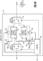
- Figure 1A is a schematic diagram of an amplifier system 1 according to one embodiment.
- the amplifier system 1 includes a voltage output amplifier 11, a current output amplifier 12, input switches 13, output switches 14, and a control circuit 19. Although one embodiment of an amplifier system is shown in Figure 1A , the teachings herein are applicable to amplifier systems implemented in a wide variety of ways.
- the amplifier system 1 includes an input terminal (IN) for receiving an input signal, such as input voltage.
- the amplifier system 1 further includes an output terminal (OUT) for driving a load 2.
- the amplifier system 1 also includes a control terminal (CTL) for receiving a control signal for selecting a particular configuration or mode of the amplifier system 1.
- the control terminal corresponds to a serial interface or bus that receives digital data indicating the desired configuration.
- the voltage output amplifier 11 and the current output amplifier 12 are electrically coupled in parallel with one another between the input terminal and the output terminal. Additionally, the input switches 13 are used to selectively provide the input signal to the voltage output amplifier 11 and/or the current output amplifier 12 for amplification. Furthermore, the output switches 14 are used to selectively connect the voltage output amplifier's voltage output to the output terminal and/or the current output amplifier's current output to the output terminal.
- the control circuit 19 controls a state of the output switches 14 to control whether or not the voltage output amplifier 11 and/or the current output amplifier 12 drive the output terminal.
- the selection of active amplifier(s) that drive the output terminal is chosen based on the control signal received by the control circuit 19. Accordingly, amplifier circuitry suitable for a particular type of load 2 can be selected.
- the selection of active amplifier(s) can be chosen based on a number of factors, such as the type of load and/or to maintain stability when operated with feedback. For instance, the selection can be based on the amount of resistance, capacitance, and/or inductance of the load 2.
- control circuit 19 also controls a state of the input switches 13 to control whether or not the voltage output amplifier 11 and/or the current output amplifier 12 receives the input signal for amplification.
- Implementing the amplifier system 1 in this manner can enhance performance, for instance, by reducing power dissipation and/or preventing an inactive amplifier from parasitically loading the input terminal and impacting input matching.
- the control circuit 19 provides a first enable signal (EN1) to the voltage output amplifier 11 and a second enable signal (EN2) to the current output amplifier 12.
- EN1 first enable signal
- EN2 second enable signal
- the control circuit 19 can advantageously power down the voltage output amplifier 11 and/or the current output amplifier 12 when a particular amplifier is not in use.
- Figure 1B is a schematic diagram of an amplifier system 21 according to another embodiment.
- the amplifier system 21 of Figure 1B includes input switches 13, output switches 14, a voltage output amplifier 31, a current output amplifier 32, a first feedback switch 33, a second feedback switch 34, a first auxiliary input switch 35, a second auxiliary input switch 36, and a control circuit 39.
- FIG. 1B shows another embodiment of an amplifier system is shown in Figure 1B , the teachings herein are applicable to amplifier systems implemented in a wide variety of ways.
- the amplifier system 21 of Figure 1B is similar to the amplifier system 1 of Figure 1A , except the amplifier system 21 of Figure 1B illustrates an implementation with additional switches and in which the voltage output amplifier 31 and the current output amplifier 32 each have a differential input with a positive or non-inverting input (+) and a negative or inverting (-) input.
- the input switches 13 are used to selectively connect the input terminal (IN) to the non-inverting input of the voltage output amplifier 31 and/or to the non-inverting input of current output amplifier 32.
- the amplifier system 21 has also been implemented with switches for controlling connectivity of the inverting inputs to the voltage output amplifier 31 and the current output amplifier 32.
- the first feedback switch 33 has been included for selectively connecting the voltage output of the voltage output amplifier 31 to the inverting input of the voltage output amplifier 31.
- the first auxiliary input switch 35 has been included for selectively connecting the inverting input of the voltage output amplifier 31 to a first input reference (REF A ), which can be, for example, an input reference voltage such as ground.
- the second feedback switch 34 has been included for selectively connecting the current output of the current output amplifier 32 to the inverting input of the current output amplifier 32.
- the second auxiliary input switch 36 has been included for selectively connecting the inverting input of the current output amplifier 32 to a second input reference (REF B ).
- control circuit 39 receives a control signal used to control the state of the amplifier system's switches, including the input switches 13, the output switches 14, the first feedback switch 33, the second feedback switch 34, the first auxiliary input switch 35, and the second auxiliary input switch 36. Additionally, the control circuit 39 processes the control signal to selectively turn on or off the voltage output amplifier 31 and to selectively turn on or off the current output amplifier 32.
- a feedback impedance (for instance, a controllable resistor and/or controllable capacitor) is included in series with the first feedback switch 33 and/or a feedback impedance is included in series with the second feedback switch 34 to provide enhanced configurability over feedback. Additionally or alternatively, a feedback impedance is included in series with the first auxiliary input switch 35 and/or a feedback impedance is included in series with the second auxiliary input switch 36 to provide enhanced configurability.
- FIG. 2 is a schematic diagram of an amplifier system 100 according to another embodiment.
- the amplifier system 100 includes an operational amplifier 101, a transconductance amplifier 102, a first input switch 111, a second input switch 112, a first output switch 113, a second output switch 114, a first feedback switch 115, a second feedback switch 116, an auxiliary input switch 117, and a control circuit 119.
- the amplifier system 100 also includes an input terminal (IN) for receiving an input signal, an output terminal (OUT) for driving a load, and a control terminal (CTL) for receiving a control signal for configuring the amplifier system 100 in a selected mode.
- INL input terminal
- CTL control terminal
- Figure 2 illustrates another embodiment of a configurable amplifier system for driving a variety of loads
- teachings herein are applicable to amplifier systems implemented in a wide variety of ways.
- the first input switch 111 selectively connects a non-inverting input of the operational amplifier 101 to the input terminal, while the second input switch selectively connects the non-inverting input of the transconductance amplifier 102 to the input terminal.
- the first output switch 113 selectively connects a voltage output of the operational amplifier 101 to the output terminal, while the second output switch 114 selectively connects the current output of the transconductance circuit 102 to the output terminal.
- the first feedback switch 115 selectively connects the voltage output and the inverting input of the operational amplifier 101 to one another, while the second feedback switch 116 selectively connects the current output and inverting input of the transconductance amplifier 102 to one another.
- the auxiliary input switch 117 selectively connects the inverting input of the transconductance amplifier 102 to a reference voltage (ground, in this example).
- the control circuit 119 controls a state of each of the switches 111-117.
- the control circuit 119 opens or closes the switches 111-117 to achieve a desired connectivity of the amplifier system 100 for a particular application.
- the selected configuration of the switches can be controlled based on the type of load coupled to the output terminal.
- the control circuit 119 provides a first power control signal (PWR1) to the operational amplifier 101, and provides a second power control signal (PWR2) to the transconductance amplifier 102.
- the power controls signals operate to select a particular power level or setting of the amplifiers. For instance, the power level can be incrementally adjusted between a low power level and a high power level. In certain implementations, the low power level is associated with disabled operation. Any number of power levels can be included. In one example, four or more power settings or modes are provided.
- power control signals are multi-bit digital signals.
- other implementations of power level control are possible, including, but not limited to, configurations using analog adjustment or tuning.
- control circuit 119 controls the power levels of the operational amplifier 101 and the transconductance amplifier 102 by controlling the amount of bias current used by each amplifier.
- other schemes of power control including, but not limited to, implementations adjusting a number of active transistors, an internal load of an amplifier, and/or transistor geometry (for instance, transistor width used for amplification).
- control circuit 119 includes a memory circuit 120, which includes digital data indicating a particular configuration of the amplifier system 100. Additionally, the memory circuit 120 receives the digital data from the control terminal CTL, which in certain implementations corresponds to a chip interface or bus.
- the memory circuit 120 includes a volatile memory that is programmed with the desired configuration of the amplifier system 100 using the control signal after power-up. For instance, a user of the amplifier system 100 can program the memory circuit 120 with data indicating the desired configuration of the amplifier system 100.
- the memory circuit 120 includes a non-volatile memory (for instance, a flash memory, a read-only memory (ROM), fuses, anti-fuses, and/or a magnetic storage device) programmed with the configuration data.
- the memory circuit 120 can be programmed after manufacture with data associated with a particular target application or load.
- Figures 3A-3C illustrate various example configurations or modes of operation of the amplifier system 100 of Figure 2 .
- the control circuit 119 of Figure 2 and associated control signaling is not depicted.
- the amplifier system 100 can be configured in a wide variety of ways and/or operate with a wide variety of types of loads. Accordingly, other implementations are possible.
- Figure 3A is a schematic diagram illustrating a first example configuration 130 of operation of the amplifier system 100 of Figure 2 .
- a resistor 131 is coupled to the output terminal (OUT). Additionally, the first input switch 111, the first output switch 113, and the first feedback switch 115 are closed, while the second input switch 112, the second output switch 114, the second feedback switch 116, and the auxiliary input switch 117 are opened. Furthermore, the operational amplifier 101 is enabled with a desired power setting using the first power control signal (PWR1) of Figure 2 . Additionally, the transconductance amplifier 102 is disabled by setting the second power control signal (PWR2) of Figure 2 to a disabled setting (indicated by a dashed outline of the transconductance amplifier 102).
- the operational amplifier 101 is enabled and configured as a unity-gain buffer, in this example. Additionally, the transconductance amplifier 102 is powered down and disconnected. The voltage output of the operational amplifier 101 drives the resistor 131, and thus the voltage at the output terminal tracks the voltage of the input terminal (IN) with relatively high precision.
- the operational amplifier 101 can include multiple stages for driving the resistor 131 with high DC gain and low DC error.
- Figure 3B is a schematic diagram illustrating a second example configuration 140 of operation of the amplifier system 100 of Figure 2 .
- a capacitor 132 is coupled to the output terminal (OUT). Additionally, the first input switch 111, the first output switch 113, the first feedback switch 115, and the auxiliary input switch 117 are opened, while the second input switch 112, the second output switch 114, and the second feedback switch 116 are closed. Furthermore, the operational amplifier 101 is disabled (indicated by a dashed outline of the operational amplifier 101) using the first power control signal (PWR1) of Figure 2 . Additionally, the transconductance amplifier 102 is enabled with a desired power setting using the second power control signal (PWR2) of Figure 2 .
- the transconductance amplifier 102 is enabled and configured as a unity-gain buffer, while the operational amplifier 101 is powered-down and disconnected. Additionally, the current output of the transconductance amplifier 102 drives the capacitor 132, and thus the voltage at the output terminal tracks the voltage of the input terminal (IN) with relatively high precision and with stability.
- the transconductance amplifier 102 can include a single gain stage for driving the capacitor 121 with robust stability performance due to only one dominant pole at the output terminal.
- Figure 3C is a schematic diagram illustrating a third example configuration 150 of operation of the amplifier system of Figure 2 .
- a resistor 131 and a capacitor 132 are coupled to the output terminal (OUT). Additionally, the first input switch 111, the second input switch 112, the first output switch 113, the second output switch 114, the first feedback switch 115, and the second feedback switch 116 are closed, while the auxiliary input switch 117 is opened.
- the operational amplifier 101 is enabled with a desired power setting using the first power control signal (PWR1) of Figure 2 .
- the transconductance amplifier 102 is also enabled with a desired power setting using the second power control signal (PWR2) of Figure 2 .
- the power settings of the operational amplifier and the transconductance amplifier 102 can be set to desired levels based on a wide variety of considerations, including, but not limited to, values of the resistor 131 and/or capacitor 132.
- a drive strength of the operational amplifier 101 can be controlled relative to that of the transconductance amplifier 102 to provide flexibility in suitably driving a particular load.
- both the operational amplifier 101 and the transconductance amplifier 102 drive the load. Additionally, the operational amplifier 101 operates to reduce or eliminate DC error arising from driving the resistor 131, while the transconductance amplifier 102 operates to maintain stability. Additionally, the power level of each amplifier is set to achieve a desired response for a given load.
- Figure 4A is a schematic diagram of one embodiment of an electronic system 200 including an amplifier system connected with feedback.
- the electronic system 200 includes an amplifier system 201, a feedback system 202, and a load 203.
- the amplifier system 201 includes an input terminal (IN) that receives an input signal from the feedback system 202. Additionally, the amplifier system 201 includes an output terminal (OUT) that drives the load 203, and a control terminal (CTL) for receiving a control signal for configuring the amplifier system 201.
- the amplifier system 201 can be implemented in accordance with any of the embodiments herein.
- the feedback system 202 receives one or more signals indicating a signaling condition of the load 203. Additionally, the feedback system 202 processes the signal(s) to control the input signal to the amplifier system 201.
- Figure 4A illustrates one embodiment of an amplifier system with feedback
- teachings herein are applicable to amplifier systems implemented in a wide variety of ways.
- Figure 4B is a schematic diagram of another embodiment of an electronic system 230 including an amplifier system connected with feedback.
- the electronic system 230 of Figure 4B is similar to the electronic system 200 of Figure 4A , except that the electronic system 230 includes a specific implementation of a feedback system 212.
- the feedback system 212 of Figure 4B includes a digital processing circuit 221, a DAC 222, an ADC 223, and a feedback amplifier 224.
- the feedback amplifier 224 processes a sensed signal from the load 203 to generate an analog feedback signal.
- the feedback amplifier 224 is a voltage gain amplifier.
- the feedback amplifier 224 is an instrumentation amplifier.
- the analog feedback signal is digitized by the ADC 223 to generate digital input data, which is processed by the digital processing circuit 221 to generate digital output data.
- the digital output data is also generated based on a digital input signal (DIN) to the digital processing circuit 221.
- the DAC 222 processes the digital output data to generate an analog input signal for the amplifier system 201.
- the digital processing circuit 221 receives the digital input signal (DIN) for enhancing the range of available processing of the feedback system 212.
- an analog input signal is provided, and an ADC digitizes the analog input signal to generate a digital representation suitable for processing by the digital processing circuit 221.
- Including the feedback system 212 provides a number of advantages, including, but not limited to, enhanced flexibility in control of feedback over a range of different configurations of the amplifier system 201 and/or different types of the load 203.
- the digital processing circuit 221 can provide digital integration, digital gain, and/or other desired digital processing to provide a type and/or an amount of feedback desirable for a particular configuration of the amplifier system 201 selected for a particular usage scenario.
- the digital processing circuit 221 can be implemented in a wide variety of ways.
- the digital processing circuit 221 includes at least one of an FPGA and/or microprocessor for providing a wide variety of types of digital processing.
- FIG. 5 is a schematic diagram of another embodiment of an electronic system 240 including an amplifier system connected with feedback.
- the electronic system 240 of Figure 5 is similar to the electronic system 230 of Figure 4B , except that the electronic system 240 includes a specific implementation of an amplifier system.
- the electronic system 240 includes the amplifier system 100 of Figure 2 .
- Figure 6A is a schematic diagram illustrating a first example configuration 280 of operation of the electronic system 240 of Figure 5 .
- a resistor 271 is coupled to the output terminal (OUT). Additionally, the first input switch 111, the first output switch 113, and the first feedback switch 115 are closed, while the second input switch 112, the second output switch 114, the second feedback switch 116, and the auxiliary input switch 117 are opened. Furthermore, the operational amplifier 101 is enabled with a desired power setting using the first power control signal (PWR1) of Figure 5 . Additionally, the transconductance amplifier 102 is disabled by setting the second power control signal (PWR2) of Figure 5 to a disabled setting (indicated by a dashed outline of the transconductance amplifier 102).
- the configuration 280 operates with example digital processing 273 including a digital integrator 274 and a digital adder 275.
- the digital adder 275 receives digital load set data, and computes the difference between the digital load set data and digital data from the ADC 223 to generate digital difference data indicating an error between the desired set point and the actual set point at the output terminal.
- the digital integrator 274 integrates the digital difference data to generate digital integration data.
- the DAC 222 controls the input signal of the operational amplifier 101 based on the digital integration data.
- the overall feedback loop of the operational amplifier 101 has high DC gain such that the voltage across the load resistor 271 is accurately set by a voltage level indicated by the digital load set data. Additionally, the digital integrator 274 provides the dominant pole in the electronic system's transfer function to thereby maintain the overall feedback loop stable.
- Figure 6B is a schematic diagram illustrating a second example configuration 290 of operation of the electronic system 240 of Figure 5 .
- a capacitor 281 is coupled to the output terminal (OUT). Additionally, the first input switch 111, the first output switch 113, the first feedback switch 115, and the second feedback switch 116 are opened, while the second input switch 112, the second output switch 114, and the auxiliary input switch 117 are closed. Furthermore, the operational amplifier 101 is disabled (indicated by a dashed outline of the operational amplifier 101) using the first power control signal (PWR1) of Figure 5 . Additionally, the transconductance amplifier 102 is enabled with a desired power setting using the second power control signal (PWR2) of Figure 5 .
- the configuration 290 operates with example digital processing 283 including a digital gain block 284 and a digital adder 275.
- the digital gain block 284 generates digital amplified data by performing digital computations representing amplification of the digital data from the ADC 223.
- the digital adder 275 also receives digital load set data, and computes the difference between the digital load set data and the digital amplified data to generate digital output data.
- the DAC 222 controls the input signal of the transconductance amplifier 102 based on the digital output data.
- FIG. 7 is a schematic diagram of a multi-chip module 310 according to one embodiment.
- the multi-chip module 310 includes a processing chip 303 and an amplifier chip 304 connected to a module substrate 301.
- a chip is also referred to herein as a semiconductor die or integrated circuit (IC).
- IC integrated circuit
- the multi-chip module 310 can also include adhesives, solder, encapsulation, surface mount components, additional pins or pads, and/or a wide variety of other structures that have been omitted for clarity of the figures.
- the multi-chip module 310 illustrates one example of an electronic module implemented in accordance with the teachings herein.
- the processing chip 303 includes the digital processing circuit 221, the DAC 222, and the ADC 223 fabricated thereon.
- the amplifier chip 304 includes the amplifier system 201 and the feedback amplifier 224 fabricated thereon.
- the amplifier chip 304 includes an input pin for receiving an input signal from the processing chip 303, and an output pin for coupling to the sensor 302 through an output pin of the multi-chip module 310.
- the amplifier chip 304 also includes a feedback input pin and a ground pin for receiving a differential feedback signal, which in this example corresponds to a voltage across the sensor 302.
- the multi-chip module 310 includes an interface or bus (BUS) that is coupled through pins of the dies to the digital processing circuit 221 and amplifier system 201.
- the bus can be used to program digital data to the processing chip 303 and amplifier chip 304 to achieve a desired configuration of the multi-chip module 310 for a given sensor 302.
- the processing IC 303 corresponds to an FPGA and/or microprocessor operable to receive digital data from the bus to control the type of feedback computations performed.
- the output pin (OUT) of the multi-chip module 310 couples to a first terminal of the sensor 302.
- the feedback input pin (FBIN) of the multi-chip module 310 also couples to the first terminal of the sensor 302.
- FBIN feedback input pin
- the multi-chip module 310 also includes a ground pin (GND) coupled to a second terminal of the sensor 302.
- GND ground pin
- the multi-chip module 310 of Figure 7 is suitable for deployment in a wide range of applications.
- the multi-chip module 310 can operate in combination with a wide variety of types of sensors, including sensors with varying impedances and/or biasing conditions.
- a multi-chip module is shown, the teachings herein are applicable to a wide variety of types of electronic systems and modules. Accordingly, other implementations are possible.
Landscapes
- Engineering & Computer Science (AREA)
- Power Engineering (AREA)
- Amplifiers (AREA)
Abstract
Description
- Embodiments of the invention relate to electronic systems, and more particularly, to amplifiers.
- Certain electronic devices employ amplifiers for processing signals. When operating open loop, such amplifiers receive an input signal and generate an output signal having a gain in comparison to the input signal. Examples of amplifiers include, but are not limited to, operational amplifiers, transimpedance amplifiers, and transconductance amplifiers. Certain amplifiers are implemented in a multi-stage configuration to enhance gain and/or performance thereof.
- Amplifier systems for driving a wide range of loads are provided herein. In certain embodiments, an amplifier system includes a voltage output amplifier and a current output amplifier that are electrically coupled in parallel with one another between an input terminal and an output terminal. The amplifier system further includes a control circuit operable to control whether or not the voltage output amplifier and/or current output amplifier drive the output terminal. Implementing the amplifier system in this manner allows the amplifier system to drive a wide range of loads. For instance, the voltage output amplifier can be suitable for driving a resistive load, while the current output amplifier can be suitable for driving a capacitive load. Moreover, for certain types of loads, such as those including a combination of resistance and capacitance, both the voltage output amplifier and the current output amplifier can be enabled to drive the load.
- Thus, including the parallel combination of the voltage output amplifier and the current output amplifier enhances flexibility of the amplifier system in driving a wide range of possible types of load. Thus, rather than needing a dedicated part (for instance, a particular chip design) for a particular type of load, the amplifier systems herein can be incorporated on a semiconductor chip suitable for driving loads of a range of different impedances. The amplifier systems herein can be used in a wide range of applications, including, but not limited to, impedance measurement. For example, an amplifier system can be used to bias and/or measure a sensor's voltage and/or current, thereby providing precision control of sensors used to detect various changes in environmental quantities or conditions.
- In one aspect, an amplifier system with controllable load driving characteristics is provided. The amplifier system includes an output terminal configured to connect to a load, a first output switch and a second output switch, a voltage output amplifier having a voltage output electrically connected to the output terminal through the first output switch, a current output amplifier having a current output electrically connected to the output terminal through the second output switch, and a control circuit configured to control the first output switch to selectively connect the voltage output of the voltage output amplifier to the output terminal, and to control the second output switch to selectively connect the current output of the current output amplifier to the output terminal.
- In another aspect, an electronic module with controllable load driving characteristics is provided. The electronic module includes a module substrate and an amplifier die attached to the module substrate. The amplifier die includes an output pin configured to provide an output signal to a load, a voltage output amplifier, a current output amplifier electrically connected in parallel with the voltage output amplifier, and a control circuit configured to control the amplifier die to selectively drive the output pin with the voltage output amplifier and to selectively drive the output pin with the current output amplifier.
- In another aspect, a method of electronic amplification with controllable load driving characteristics is provided. The method includes receiving a control signal as an input to an amplifier system, the control signal indicating a selected mode of the amplifier system chosen from a plurality of modes including a first mode, a second mode, and a third mode. The method further includes controlling an output terminal of the amplifier system with a voltage output amplifier in response to the control signal indicating the selected mode is the first mode, controlling the output terminal with a current output amplifier in response to the control signal indicating the selected mode is the second mode, and controlling the output terminal with both the voltage output amplifier and the current output amplifier in response to the control signal indicating the selected mode is the third mode.
-
-
Figure 1A is a schematic diagram of an amplifier system according to one embodiment. -
Figure 1B is a schematic diagram of an amplifier system according to another embodiment. -
Figure 2 is a schematic diagram of an amplifier system according to another embodiment. -
Figure 3A is a schematic diagram illustrating a first example configuration of operation of the amplifier system ofFigure 2 . -
Figure 3B is a schematic diagram illustrating a second example configuration of operation of the amplifier system ofFigure 2 . -
Figure 3C is a schematic diagram illustrating a third example configuration of operation of the amplifier system ofFigure 2 . -
Figure 4A is a schematic diagram of one embodiment of an electronic system including an amplifier system connected with feedback. -
Figure 4B is a schematic diagram of another embodiment of an electronic system including an amplifier system connected with feedback. -
Figure 5 is a schematic diagram of another embodiment of an electronic system including an amplifier system connected with feedback. -
Figure 6A is a schematic diagram illustrating a first example configuration of operation of the electronic system ofFigure 5 . -
Figure 6B is a schematic diagram illustrating a second example configuration of operation of the electronic system ofFigure 5 . -
Figure 7 is a schematic diagram of a multi-chip module according to one embodiment. - The following detailed description of embodiments presents various descriptions of specific embodiments of the invention. However, the invention can be embodied in a multitude of different ways. In this description, reference is made to the drawings where like reference numerals may indicate identical or functionally similar elements. It will be understood that elements illustrated in the figures are not necessarily drawn to scale. Moreover, it will be understood that certain embodiments can include more elements than illustrated in a drawing and/or a subset of the elements illustrated in a drawing. Further, some embodiments can incorporate any suitable combination of features from two or more drawings.
- Amplifier systems for driving a wide range of loads are provided herein. In certain embodiments, an amplifier system includes a voltage output amplifier and a current output amplifier that are electrically coupled in parallel with one another between an input terminal and an output terminal. The amplifier system further includes a control circuit operable to control whether or not the voltage output amplifier and/or current output amplifier drive the output terminal.
- Implementing the amplifier system in this manner allows the amplifier system to drive a wide range of loads. For instance, the voltage output amplifier can be suitable for driving a resistive load, and thus the voltage output amplifier can be enabled and the current output amplifier disabled when a resistor or other resistive load is coupled to the output terminal. Additionally, the current output amplifier can be suitable for driving a capacitive load, and thus the current output amplifier can be enabled and the voltage output amplifier disabled when a capacitor or other capacitive load is coupled to the output terminal. Moreover, for certain types of loads, such as those including a combination of resistance and capacitance, both the voltage output amplifier and the current output amplifier can be enabled to drive the load.
- Thus, including the parallel combination of the voltage output amplifier and the current output amplifier enhances flexibility of the amplifier system in driving a wide range of possible types of load. Thus, rather than needing a dedicated part (for instance, a particular chip design) for a particular type of load, the amplifier systems herein can be incorporated on a semiconductor chip suitable for driving loads of a range of different impedances.
- In certain implementations, the voltage output amplifier is implemented as an operational amplifier including two or more stages arranged in a cascade. For example, such a multi-stage operational amplifier includes an output stage that provides buffering to aid in driving a resistive load. The current output amplifier can be implemented in a wide variety of ways. In certain implementations, the current output amplifier is implemented as a transconductance amplifier having a single stage and a current output suitable for driving a capacitive load.
- The amplifier systems herein operate stably when connected with negative feedback. For example, when driving a resistive load, the voltage output amplifier can be enabled to drive the resistive load without oscillation or other instability. Additionally, when driving a capacitive load, the current output amplifier can be enabled to drive the capacitive load without stability problems.
- In contrast, an amplifier system with only a voltage output amplifier or only a current output amplifier can exhibit unstable behavior under certain load conditions. For instance, an operational amplifier can suffer from instability when driving a capacitive load and/or a transconductance amplifier can suffer from instability when driving a resistive load.
- In certain implementations, the amplifier system includes input switches for selectively providing an input signal (for instance, an input voltage) received from the input terminal to an input of the voltage output amplifier and/or to an input of the current output amplifier. Furthermore, the amplifier system can include output switches for selectively connecting the output terminal to the voltage output of the voltage output amplifier and/or to the current output of the current output amplifier.
- Implementing the amplifier system in this manner aids in decoupling an inactive amplifier from the input terminal and/or output terminal of the amplifier system. This in turn provides a number of advantages, including, but not limited to, inhibiting an inactive amplifier from impacting signaling, impedance matching, and/or other performance characteristics of the amplifier system.
- To further enhance configurability, the amplifier system can be implemented with switches for selectively providing local feedback to the voltage output amplifier and/or to the current output amplifier. Additionally or alternatively, switches can be included for selectively inputting other signals to the voltage output amplifier and/or current output amplifier, including, but not limited to, input reference signals used for differential amplification.
- In certain implementations, an unused amplifier is powered off to reduce power dissipation and/or heat generation. For example, when the voltage output amplifier is driving the output terminal, the current output amplifier can be powered down. Likewise, when the current output amplifier is driving the output terminal, the voltage output amplifier can be powered down.
- In certain implementations, the voltage output amplifier and/or the current output amplifier has a power level (for instance, an amount of gain) that can be incrementally adjusted, for instance, between a lowest power level associated with disabled operation to a highest power level associated with high gain operation. By implementing the amplifier system in this manner, enhanced configurability is provided, thereby expanding a range of applications that the amplifier system can be deployed in. The power level of an amplifier can be controlled in a wide variety of ways, including, but not limited to, by adjustment of the amplifier's bias current.
- In certain implementations, the amplifier system is coupled to an interface or bus, such as an inter-Integrated Circuit (I2C) bus, a General Purpose Input Output (GPIO) bus, and/or other suitable interface. Additionally, the amplifier system's control circuit receives digital data from the bus used to control switch connectivity and/or state of the amplifiers. For example, the amplifier system can be fabricated on a semiconductor die or chip, and a user can digitally program a desired configuration or mode of the amplifier system using the bus. Implementing the amplifier system in this manner provides a convenient and flexible mechanism for user configurability.
- The amplifier systems herein can be used in a wide range of applications, including, but not limited to, impedance measurement. For example, an amplifier system can be used to bias and/or measure a sensor's voltage and/or current, thereby providing precision control of sensors used to detect various changes in environmental quantities or conditions.
- In certain implementations, a feedback system is included for controlling feedback provided from the output terminal to the input terminal of the amplifier system. In one example, the feedback system includes a feedback amplifier for coupling to the output terminal, an analog-to-digital converter (ADC) for generating digital input data based on an analog feedback signal from the feedback amplifier, a digital processing circuit for processing the digital input data to generate digital output data, and a digital-to-analog converter (DAC) for generating an analog feedback signal for the amplifier system based on the digital output data.
- Implementing the feedback system in this manner can provide a number of advantages, including, but not limited to, enhanced flexibility in control of feedback over a range of different configurations of the amplifier system. For example, the digital processing circuit can provide digital integration, digital gain, and/or other desired digital processing to provide a type of feedback desirable for a particular configuration of the amplifier system chosen for a given application and/or type of load.
- In certain implementations, a processing chip, such as a field-programmable gate array (FPGA) and/or microprocessor, is commonly packaged with an amplifier chip in a multi-chip module. The amplifier chip can include the configurable amplifier system thereon and at least one feedback amplifier for generating an analog feedback signal based on monitoring signaling conditions of an external load, such as a sensor external to the multi-chip module. Additionally, the analog feedback signal is processed by the processing chip to generate an input signal for the amplifier chip. Such multi-chip modules are suitable for deployment in a wide range of applications.
-
Figure 1A is a schematic diagram of anamplifier system 1 according to one embodiment. Theamplifier system 1 includes avoltage output amplifier 11, acurrent output amplifier 12, input switches 13, output switches 14, and acontrol circuit 19. Although one embodiment of an amplifier system is shown inFigure 1A , the teachings herein are applicable to amplifier systems implemented in a wide variety of ways. - With continuing reference to
Figure 1A , theamplifier system 1 includes an input terminal (IN) for receiving an input signal, such as input voltage. Theamplifier system 1 further includes an output terminal (OUT) for driving aload 2. Theamplifier system 1 also includes a control terminal (CTL) for receiving a control signal for selecting a particular configuration or mode of theamplifier system 1. In certain implementations, the control terminal corresponds to a serial interface or bus that receives digital data indicating the desired configuration. - The
voltage output amplifier 11 and thecurrent output amplifier 12 are electrically coupled in parallel with one another between the input terminal and the output terminal. Additionally, the input switches 13 are used to selectively provide the input signal to thevoltage output amplifier 11 and/or thecurrent output amplifier 12 for amplification. Furthermore, the output switches 14 are used to selectively connect the voltage output amplifier's voltage output to the output terminal and/or the current output amplifier's current output to the output terminal. - As shown in
Figure 1A , thecontrol circuit 19 controls a state of the output switches 14 to control whether or not thevoltage output amplifier 11 and/or thecurrent output amplifier 12 drive the output terminal. The selection of active amplifier(s) that drive the output terminal is chosen based on the control signal received by thecontrol circuit 19. Accordingly, amplifier circuitry suitable for a particular type ofload 2 can be selected. The selection of active amplifier(s) can be chosen based on a number of factors, such as the type of load and/or to maintain stability when operated with feedback. For instance, the selection can be based on the amount of resistance, capacitance, and/or inductance of theload 2. - In the illustrated embodiment, the
control circuit 19 also controls a state of the input switches 13 to control whether or not thevoltage output amplifier 11 and/or thecurrent output amplifier 12 receives the input signal for amplification. Implementing theamplifier system 1 in this manner can enhance performance, for instance, by reducing power dissipation and/or preventing an inactive amplifier from parasitically loading the input terminal and impacting input matching. - With continuing reference to
Figure 1A , thecontrol circuit 19 provides a first enable signal (EN1) to thevoltage output amplifier 11 and a second enable signal (EN2) to thecurrent output amplifier 12. By implementing thecontrol circuit 19 in this manner, thecontrol circuit 19 can advantageously power down thevoltage output amplifier 11 and/or thecurrent output amplifier 12 when a particular amplifier is not in use. -
Figure 1B is a schematic diagram of anamplifier system 21 according to another embodiment. Theamplifier system 21 ofFigure 1B includes input switches 13, output switches 14, avoltage output amplifier 31, acurrent output amplifier 32, a first feedback switch 33, asecond feedback switch 34, a firstauxiliary input switch 35, a secondauxiliary input switch 36, and acontrol circuit 39. Although another embodiment of an amplifier system is shown inFigure 1B , the teachings herein are applicable to amplifier systems implemented in a wide variety of ways. - The
amplifier system 21 ofFigure 1B is similar to theamplifier system 1 ofFigure 1A , except theamplifier system 21 ofFigure 1B illustrates an implementation with additional switches and in which thevoltage output amplifier 31 and thecurrent output amplifier 32 each have a differential input with a positive or non-inverting input (+) and a negative or inverting (-) input. - In the illustrated embodiment, the input switches 13 are used to selectively connect the input terminal (IN) to the non-inverting input of the
voltage output amplifier 31 and/or to the non-inverting input ofcurrent output amplifier 32. - With continuing reference to
Figure 1B , theamplifier system 21 has also been implemented with switches for controlling connectivity of the inverting inputs to thevoltage output amplifier 31 and thecurrent output amplifier 32. - For example, as shown in
Figure 1B , the first feedback switch 33 has been included for selectively connecting the voltage output of thevoltage output amplifier 31 to the inverting input of thevoltage output amplifier 31. Additionally, the firstauxiliary input switch 35 has been included for selectively connecting the inverting input of thevoltage output amplifier 31 to a first input reference (REFA), which can be, for example, an input reference voltage such as ground. Furthermore, thesecond feedback switch 34 has been included for selectively connecting the current output of thecurrent output amplifier 32 to the inverting input of thecurrent output amplifier 32. Additionally, the secondauxiliary input switch 36 has been included for selectively connecting the inverting input of thecurrent output amplifier 32 to a second input reference (REFB). - In the illustrated embodiment, the
control circuit 39 receives a control signal used to control the state of the amplifier system's switches, including the input switches 13, the output switches 14, the first feedback switch 33, thesecond feedback switch 34, the firstauxiliary input switch 35, and the secondauxiliary input switch 36. Additionally, thecontrol circuit 39 processes the control signal to selectively turn on or off thevoltage output amplifier 31 and to selectively turn on or off thecurrent output amplifier 32. - In certain implementations, a feedback impedance (for instance, a controllable resistor and/or controllable capacitor) is included in series with the first feedback switch 33 and/or a feedback impedance is included in series with the
second feedback switch 34 to provide enhanced configurability over feedback. Additionally or alternatively, a feedback impedance is included in series with the firstauxiliary input switch 35 and/or a feedback impedance is included in series with the secondauxiliary input switch 36 to provide enhanced configurability. -
Figure 2 is a schematic diagram of anamplifier system 100 according to another embodiment. Theamplifier system 100 includes anoperational amplifier 101, atransconductance amplifier 102, afirst input switch 111, asecond input switch 112, afirst output switch 113, asecond output switch 114, afirst feedback switch 115, asecond feedback switch 116, anauxiliary input switch 117, and acontrol circuit 119. As shown inFigure 2 , theamplifier system 100 also includes an input terminal (IN) for receiving an input signal, an output terminal (OUT) for driving a load, and a control terminal (CTL) for receiving a control signal for configuring theamplifier system 100 in a selected mode. - Although
Figure 2 illustrates another embodiment of a configurable amplifier system for driving a variety of loads, the teachings herein are applicable to amplifier systems implemented in a wide variety of ways. - The
first input switch 111 selectively connects a non-inverting input of theoperational amplifier 101 to the input terminal, while the second input switch selectively connects the non-inverting input of thetransconductance amplifier 102 to the input terminal. Additionally, thefirst output switch 113 selectively connects a voltage output of theoperational amplifier 101 to the output terminal, while thesecond output switch 114 selectively connects the current output of thetransconductance circuit 102 to the output terminal. - With continuing reference to
Figure 2 , thefirst feedback switch 115 selectively connects the voltage output and the inverting input of theoperational amplifier 101 to one another, while thesecond feedback switch 116 selectively connects the current output and inverting input of thetransconductance amplifier 102 to one another. In this embodiment, theauxiliary input switch 117 selectively connects the inverting input of thetransconductance amplifier 102 to a reference voltage (ground, in this example). - As shown in
Figure 2 , thecontrol circuit 119 controls a state of each of the switches 111-117. Thus, thecontrol circuit 119 opens or closes the switches 111-117 to achieve a desired connectivity of theamplifier system 100 for a particular application. For instance, the selected configuration of the switches can be controlled based on the type of load coupled to the output terminal. - As shown in
Figure 2 , thecontrol circuit 119 provides a first power control signal (PWR1) to theoperational amplifier 101, and provides a second power control signal (PWR2) to thetransconductance amplifier 102. The power controls signals operate to select a particular power level or setting of the amplifiers. For instance, the power level can be incrementally adjusted between a low power level and a high power level. In certain implementations, the low power level is associated with disabled operation. Any number of power levels can be included. In one example, four or more power settings or modes are provided. - By providing control over power setting, enhanced configurability is provided. In certain implementations, power control signals are multi-bit digital signals. However, other implementations of power level control are possible, including, but not limited to, configurations using analog adjustment or tuning.
- In certain implementations, the
control circuit 119 controls the power levels of theoperational amplifier 101 and thetransconductance amplifier 102 by controlling the amount of bias current used by each amplifier. However, other schemes of power control are possible, including, but not limited to, implementations adjusting a number of active transistors, an internal load of an amplifier, and/or transistor geometry (for instance, transistor width used for amplification). - In the illustrated embodiment, the
control circuit 119 includes amemory circuit 120, which includes digital data indicating a particular configuration of theamplifier system 100. Additionally, thememory circuit 120 receives the digital data from the control terminal CTL, which in certain implementations corresponds to a chip interface or bus. - In certain implementations, the
memory circuit 120 includes a volatile memory that is programmed with the desired configuration of theamplifier system 100 using the control signal after power-up. For instance, a user of theamplifier system 100 can program thememory circuit 120 with data indicating the desired configuration of theamplifier system 100. However, other configurations are possible, such as implementations in which thememory circuit 120 includes a non-volatile memory (for instance, a flash memory, a read-only memory (ROM), fuses, anti-fuses, and/or a magnetic storage device) programmed with the configuration data. In such implementations, thememory circuit 120 can be programmed after manufacture with data associated with a particular target application or load. -
Figures 3A-3C illustrate various example configurations or modes of operation of theamplifier system 100 ofFigure 2 . For clarity of the figures, thecontrol circuit 119 ofFigure 2 and associated control signaling is not depicted. Although three example configurations of operation are shown, theamplifier system 100 can be configured in a wide variety of ways and/or operate with a wide variety of types of loads. Accordingly, other implementations are possible. -
Figure 3A is a schematic diagram illustrating afirst example configuration 130 of operation of theamplifier system 100 ofFigure 2 . - In this example, a
resistor 131 is coupled to the output terminal (OUT). Additionally, thefirst input switch 111, thefirst output switch 113, and thefirst feedback switch 115 are closed, while thesecond input switch 112, thesecond output switch 114, thesecond feedback switch 116, and theauxiliary input switch 117 are opened. Furthermore, theoperational amplifier 101 is enabled with a desired power setting using the first power control signal (PWR1) ofFigure 2 . Additionally, thetransconductance amplifier 102 is disabled by setting the second power control signal (PWR2) ofFigure 2 to a disabled setting (indicated by a dashed outline of the transconductance amplifier 102). - With continuing reference to
Figure 3A , theoperational amplifier 101 is enabled and configured as a unity-gain buffer, in this example. Additionally, thetransconductance amplifier 102 is powered down and disconnected. The voltage output of theoperational amplifier 101 drives theresistor 131, and thus the voltage at the output terminal tracks the voltage of the input terminal (IN) with relatively high precision. For example, theoperational amplifier 101 can include multiple stages for driving theresistor 131 with high DC gain and low DC error. -
Figure 3B is a schematic diagram illustrating asecond example configuration 140 of operation of theamplifier system 100 ofFigure 2 . - In this example, a
capacitor 132 is coupled to the output terminal (OUT). Additionally, thefirst input switch 111, thefirst output switch 113, thefirst feedback switch 115, and theauxiliary input switch 117 are opened, while thesecond input switch 112, thesecond output switch 114, and thesecond feedback switch 116 are closed. Furthermore, theoperational amplifier 101 is disabled (indicated by a dashed outline of the operational amplifier 101) using the first power control signal (PWR1) ofFigure 2 . Additionally, thetransconductance amplifier 102 is enabled with a desired power setting using the second power control signal (PWR2) ofFigure 2 . - In the
configuration 140 ofFigure 3B , thetransconductance amplifier 102 is enabled and configured as a unity-gain buffer, while theoperational amplifier 101 is powered-down and disconnected. Additionally, the current output of thetransconductance amplifier 102 drives thecapacitor 132, and thus the voltage at the output terminal tracks the voltage of the input terminal (IN) with relatively high precision and with stability. For example, thetransconductance amplifier 102 can include a single gain stage for driving the capacitor 121 with robust stability performance due to only one dominant pole at the output terminal. -
Figure 3C is a schematic diagram illustrating athird example configuration 150 of operation of the amplifier system ofFigure 2 . - In this example, a
resistor 131 and acapacitor 132 are coupled to the output terminal (OUT). Additionally, thefirst input switch 111, thesecond input switch 112, thefirst output switch 113, thesecond output switch 114, thefirst feedback switch 115, and thesecond feedback switch 116 are closed, while theauxiliary input switch 117 is opened. - Furthermore, the
operational amplifier 101 is enabled with a desired power setting using the first power control signal (PWR1) ofFigure 2 . Additionally, thetransconductance amplifier 102 is also enabled with a desired power setting using the second power control signal (PWR2) ofFigure 2 . The power settings of the operational amplifier and thetransconductance amplifier 102 can be set to desired levels based on a wide variety of considerations, including, but not limited to, values of theresistor 131 and/orcapacitor 132. Thus, a drive strength of theoperational amplifier 101 can be controlled relative to that of thetransconductance amplifier 102 to provide flexibility in suitably driving a particular load. - In the
configuration 150 ofFigure 3C , both theoperational amplifier 101 and thetransconductance amplifier 102 drive the load. Additionally, theoperational amplifier 101 operates to reduce or eliminate DC error arising from driving theresistor 131, while thetransconductance amplifier 102 operates to maintain stability. Additionally, the power level of each amplifier is set to achieve a desired response for a given load. -
Figure 4A is a schematic diagram of one embodiment of anelectronic system 200 including an amplifier system connected with feedback. Theelectronic system 200 includes anamplifier system 201, afeedback system 202, and aload 203. - As shown in
Figure 4A , theamplifier system 201 includes an input terminal (IN) that receives an input signal from thefeedback system 202. Additionally, theamplifier system 201 includes an output terminal (OUT) that drives theload 203, and a control terminal (CTL) for receiving a control signal for configuring theamplifier system 201. Theamplifier system 201 can be implemented in accordance with any of the embodiments herein. - In the illustrated embodiment, the
feedback system 202 receives one or more signals indicating a signaling condition of theload 203. Additionally, thefeedback system 202 processes the signal(s) to control the input signal to theamplifier system 201. - Although
Figure 4A illustrates one embodiment of an amplifier system with feedback, the teachings herein are applicable to amplifier systems implemented in a wide variety of ways. -
Figure 4B is a schematic diagram of another embodiment of anelectronic system 230 including an amplifier system connected with feedback. Theelectronic system 230 ofFigure 4B is similar to theelectronic system 200 ofFigure 4A , except that theelectronic system 230 includes a specific implementation of afeedback system 212. - The
feedback system 212 ofFigure 4B includes adigital processing circuit 221, aDAC 222, anADC 223, and afeedback amplifier 224. Thefeedback amplifier 224 processes a sensed signal from theload 203 to generate an analog feedback signal. In certain implementations, thefeedback amplifier 224 is a voltage gain amplifier. In certain implementations, thefeedback amplifier 224 is an instrumentation amplifier. - With continuing reference to
Figure 4B , the analog feedback signal is digitized by theADC 223 to generate digital input data, which is processed by thedigital processing circuit 221 to generate digital output data. In certain implementations, the digital output data is also generated based on a digital input signal (DIN) to thedigital processing circuit 221. TheDAC 222 processes the digital output data to generate an analog input signal for theamplifier system 201. In this example, thedigital processing circuit 221 receives the digital input signal (DIN) for enhancing the range of available processing of thefeedback system 212. Additionally or alternatively, an analog input signal is provided, and an ADC digitizes the analog input signal to generate a digital representation suitable for processing by thedigital processing circuit 221. - Including the
feedback system 212 provides a number of advantages, including, but not limited to, enhanced flexibility in control of feedback over a range of different configurations of theamplifier system 201 and/or different types of theload 203. For example, thedigital processing circuit 221 can provide digital integration, digital gain, and/or other desired digital processing to provide a type and/or an amount of feedback desirable for a particular configuration of theamplifier system 201 selected for a particular usage scenario. - The
digital processing circuit 221 can be implemented in a wide variety of ways. In certain implementations, thedigital processing circuit 221 includes at least one of an FPGA and/or microprocessor for providing a wide variety of types of digital processing. -
Figure 5 is a schematic diagram of another embodiment of anelectronic system 240 including an amplifier system connected with feedback. Theelectronic system 240 ofFigure 5 is similar to theelectronic system 230 ofFigure 4B , except that theelectronic system 240 includes a specific implementation of an amplifier system. In particular, theelectronic system 240 includes theamplifier system 100 ofFigure 2 . -
Figure 6A is a schematic diagram illustrating afirst example configuration 280 of operation of theelectronic system 240 ofFigure 5 . - In this example, a
resistor 271 is coupled to the output terminal (OUT). Additionally, thefirst input switch 111, thefirst output switch 113, and thefirst feedback switch 115 are closed, while thesecond input switch 112, thesecond output switch 114, thesecond feedback switch 116, and theauxiliary input switch 117 are opened. Furthermore, theoperational amplifier 101 is enabled with a desired power setting using the first power control signal (PWR1) ofFigure 5 . Additionally, thetransconductance amplifier 102 is disabled by setting the second power control signal (PWR2) ofFigure 5 to a disabled setting (indicated by a dashed outline of the transconductance amplifier 102). - With continuing reference to
Figure 6A , theconfiguration 280 operates with exampledigital processing 273 including adigital integrator 274 and adigital adder 275. Thedigital adder 275 receives digital load set data, and computes the difference between the digital load set data and digital data from theADC 223 to generate digital difference data indicating an error between the desired set point and the actual set point at the output terminal. Thedigital integrator 274 integrates the digital difference data to generate digital integration data. TheDAC 222 controls the input signal of theoperational amplifier 101 based on the digital integration data. - By configuring the electronic system in this manner, the overall feedback loop of the
operational amplifier 101 has high DC gain such that the voltage across theload resistor 271 is accurately set by a voltage level indicated by the digital load set data. Additionally, thedigital integrator 274 provides the dominant pole in the electronic system's transfer function to thereby maintain the overall feedback loop stable. -
Figure 6B is a schematic diagram illustrating asecond example configuration 290 of operation of theelectronic system 240 ofFigure 5 . - In this example, a
capacitor 281 is coupled to the output terminal (OUT). Additionally, thefirst input switch 111, thefirst output switch 113, thefirst feedback switch 115, and thesecond feedback switch 116 are opened, while thesecond input switch 112, thesecond output switch 114, and theauxiliary input switch 117 are closed. Furthermore, theoperational amplifier 101 is disabled (indicated by a dashed outline of the operational amplifier 101) using the first power control signal (PWR1) ofFigure 5 . Additionally, thetransconductance amplifier 102 is enabled with a desired power setting using the second power control signal (PWR2) ofFigure 5 . - With continuing reference to
Figure 6B , theconfiguration 290 operates with exampledigital processing 283 including adigital gain block 284 and adigital adder 275. Thedigital gain block 284 generates digital amplified data by performing digital computations representing amplification of the digital data from theADC 223. Thedigital adder 275 also receives digital load set data, and computes the difference between the digital load set data and the digital amplified data to generate digital output data. TheDAC 222 controls the input signal of thetransconductance amplifier 102 based on the digital output data. - By configuring the electronic system in this manner, constant digital gain over frequency is provided. Additionally, high DC gain and a dominant pole are provided by the
transconductance amplifier 102 driving theload capacitor 281. -
Figure 7 is a schematic diagram of amulti-chip module 310 according to one embodiment. Themulti-chip module 310 includes a processing chip 303 and anamplifier chip 304 connected to amodule substrate 301. A chip is also referred to herein as a semiconductor die or integrated circuit (IC). Although depicted schematically, themulti-chip module 310 can also include adhesives, solder, encapsulation, surface mount components, additional pins or pads, and/or a wide variety of other structures that have been omitted for clarity of the figures. - The
multi-chip module 310 illustrates one example of an electronic module implemented in accordance with the teachings herein. In the illustrated embodiment, the processing chip 303 includes thedigital processing circuit 221, theDAC 222, and theADC 223 fabricated thereon. Additionally, theamplifier chip 304 includes theamplifier system 201 and thefeedback amplifier 224 fabricated thereon. Theamplifier chip 304 includes an input pin for receiving an input signal from the processing chip 303, and an output pin for coupling to thesensor 302 through an output pin of themulti-chip module 310. Theamplifier chip 304 also includes a feedback input pin and a ground pin for receiving a differential feedback signal, which in this example corresponds to a voltage across thesensor 302. - In the illustrated embodiment, the
multi-chip module 310 includes an interface or bus (BUS) that is coupled through pins of the dies to thedigital processing circuit 221 andamplifier system 201. The bus can be used to program digital data to the processing chip 303 andamplifier chip 304 to achieve a desired configuration of themulti-chip module 310 for a givensensor 302. In certain implementations, the processing IC 303 corresponds to an FPGA and/or microprocessor operable to receive digital data from the bus to control the type of feedback computations performed. - As shown in
Figure 7 , the output pin (OUT) of themulti-chip module 310 couples to a first terminal of thesensor 302. In this example, the feedback input pin (FBIN) of themulti-chip module 310 also couples to the first terminal of thesensor 302. However, other implementations are possible, such as implementations using different configurations of feedback. Including an output pin and a separate feedback input pin enhances the flexibility of themulti-chip module 310. In this example, themulti-chip module 310 also includes a ground pin (GND) coupled to a second terminal of thesensor 302. Thus, a voltage across thesensor 302 is provided to thefeedback amplifier 224 to thereby monitor signaling conditions of thesensor 302. - The
multi-chip module 310 ofFigure 7 is suitable for deployment in a wide range of applications. For example, themulti-chip module 310 can operate in combination with a wide variety of types of sensors, including sensors with varying impedances and/or biasing conditions. Although one example of a multi-chip module is shown, the teachings herein are applicable to a wide variety of types of electronic systems and modules. Accordingly, other implementations are possible. - The foregoing description may refer to elements or features as being "connected" or "coupled" together. As used herein, unless expressly stated otherwise, "connected" means that one element/feature is directly or indirectly connected to another element/feature, and not necessarily mechanically. Likewise, unless expressly stated otherwise, "coupled" means that one element/feature is directly or indirectly coupled to another element/feature, and not necessarily mechanically. Thus, although the various schematics shown in the figures depict example arrangements of elements and components, additional intervening elements, devices, features, or components may be present in an actual embodiment (assuming that the functionality of the depicted circuits is not adversely affected).
- While certain embodiments have been described, these embodiments have been presented by way of example only, and are not intended to limit the scope of the disclosure. Indeed, the novel apparatus, methods, and systems described herein may be embodied in a variety of other forms; furthermore, various omissions, substitutions and changes in the form of the methods and systems described herein may be made without departing from the spirit of the disclosure. For example, while the disclosed embodiments are presented in a given arrangement, alternative embodiments may perform similar functionalities with different components and/or circuit topologies, and some elements may be deleted, moved, added, subdivided, combined, and/or modified. Each of these elements may be implemented in a variety of different ways. Any suitable combination of the elements and acts of the various embodiments described above can be combined to provide further embodiments. Accordingly, the scope of the present invention is defined only by reference to the appended claims.
- Although the claims presented here are in single dependency format for filing at the USPTO, it is to be understood that any claim may depend on any preceding claim of the same type except when that is clearly not technically feasible.
Claims (15)
- An amplifier system with controllable load driving characteristics, the amplifier system comprising:an output terminal configured to connect to a load;a first output switch and a second output switch;a voltage output amplifier having a voltage output electrically connected to the output terminal through the first output switch;a current output amplifier having a current output electrically connected to the output terminal through the second output switch; anda control circuit configured to control the first output switch to selectively connect the voltage output of the voltage output amplifier to the output terminal, and to control the second output switch to selectively connect the current output of the current output amplifier to the output terminal.
- The amplifier system of Claim 1, wherein the voltage output amplifier is an operational amplifier and the current output amplifier is a transconductance amplifier.
- The amplifier system of Claim 2, wherein the control circuit is operable in a first mode in which the operational amplifier drives the output terminal and the transconductance amplifier is disabled, a second mode in which the transconductance amplifier drives the output terminal and the operational amplifier is disabled, and a third mode in which both the operational amplifier and the transconductance amplifier drive the output terminal.
- The amplifier system of Claims 2 or 3, further comprising a first feedback switch controlled by the control circuit and electrically connected between the voltage output and an inverting input of the operational amplifier, and a second feedback switch controlled by the control circuit and electrically connected between the current output and an inverting input of the transconductance amplifier.
- The amplifier system of Claims 2, 3 or 4, further comprising an auxiliary input switch controlled by the control circuit and electrically connected between a reference voltage and an inverting input of the transconductance amplifier.
- The amplifier system of any preceding Claim, wherein the control circuit is further configured to disable the voltage output amplifier when the first output switch is opened, and to disable the current output amplifier when the second output switch is opened.
- The amplifier system of any preceding Claim, further comprising a first input switch controlled by the control circuit and coupled between an input terminal and an input of the voltage output amplifier, and a second input switch controlled by the control circuit and coupled between the input terminal and an input to the current output amplifier; and optionally further comprising a feedback amplifier including an input coupled to the output terminal and an output configured to generate a feedback signal for controlling the input terminal.
- The amplifier system of any preceding Claim, wherein at least one of the voltage output amplifier or the current output amplifier has an adjustable power level controlled by the control circuit.
- The amplifier system of any preceding Claim, wherein the control circuit is further configured to receive digital data over an interface, and to control the first output switch and the second output switch based on the digital data.
- An electronic module with controllable load driving characteristics, the electronic module comprising:a module substrate; andan amplifier die attached to the module substrate, the amplifier die comprising:an output pin configured to provide an output signal to a load;a voltage output amplifier;a current output amplifier electrically connected in parallel with the voltage output amplifier; anda control circuit configured to control the amplifier die to selectively drive the output pin with the voltage output amplifier and to selectively drive the output pin with the current output amplifier.
- The electronic module of Claim 10, wherein the control circuit is operable in a first mode in which the voltage output amplifier drives the output pin and the current output amplifier is disabled, a second mode in which the current output amplifier drives the output pin and the voltage output amplifier is disabled, and a third mode in which both the voltage output amplifier and the current output amplifier drive the output pin.
- The electronic module of Claims 10 or 11, further comprising a processing die attached to the module substrate and configured to provide an input signal to an input pin of the amplifier die; and optionally wherein the amplifier die further comprises a feedback amplifier including an input coupled to the output pin and an output that generates an analog feedback signal.
- The electronic module of Claim 12, wherein the processing die includes an ADC configured to generate digital input data based on the analog feedback signal, a digital processing circuit configured to process the digital input data to generate digital output data, and a DAC configured to generate the input signal based on the digital output data.
- A method of electronic amplification with controllable load driving characteristics, the method comprising:receiving a control signal as an input to an amplifier system, the control signal indicating a selected mode of the amplifier system chosen from a plurality of modes including a first mode, a second mode, and a third mode;controlling an output terminal of the amplifier system with a voltage output amplifier in response to the control signal indicating the selected mode is the first mode;controlling the output terminal with a current output amplifier in response to the control signal indicating the selected mode is the second mode; andcontrolling the output terminal with both the voltage output amplifier and the current output amplifier in response to the control signal indicating the selected mode is the third mode.
- The method of Claim 14, further comprising one or more of:disabling the current output amplifier in the first mode, and disabling the voltage output amplifier in the second mode;controlling an adjustable power level of at least one of the voltage output amplifier or the current output amplifier based on the control signal;receiving the control signal as digital data over an interface; andcontrolling an amount of local feedback to at least one of the voltage output amplifier or the current output amplifier based on the control signal.
Applications Claiming Priority (1)
| Application Number | Priority Date | Filing Date | Title |
|---|---|---|---|
| US16/162,858 US10756676B2 (en) | 2018-10-17 | 2018-10-17 | Amplifier systems for driving a wide range of loads |
Publications (2)
| Publication Number | Publication Date |
|---|---|
| EP3641130A1 true EP3641130A1 (en) | 2020-04-22 |
| EP3641130B1 EP3641130B1 (en) | 2022-03-09 |
Family
ID=68280906
Family Applications (1)
| Application Number | Title | Priority Date | Filing Date |
|---|---|---|---|
| EP19202858.7A Active EP3641130B1 (en) | 2018-10-17 | 2019-10-11 | Amplifier systems for driving a wide range of loads |
Country Status (3)
| Country | Link |
|---|---|
| US (1) | US10756676B2 (en) |
| EP (1) | EP3641130B1 (en) |
| CN (1) | CN111064435B (en) |
Families Citing this family (7)
| Publication number | Priority date | Publication date | Assignee | Title |
|---|---|---|---|---|
| TWI710209B (en) * | 2019-07-02 | 2020-11-11 | 立積電子股份有限公司 | Amplifying apparatus |
| US11151150B2 (en) * | 2019-09-13 | 2021-10-19 | Salesforce.Com, Inc. | Adjustable connection pool mechanism |
| US11636067B2 (en) | 2019-10-04 | 2023-04-25 | Salesforce.Com, Inc. | Performance measurement mechanism |
| US11165857B2 (en) | 2019-10-23 | 2021-11-02 | Salesforce.Com, Inc. | Connection pool anomaly detection mechanism |
| US11757750B2 (en) * | 2020-04-15 | 2023-09-12 | Level 3 Communications, Llc | Traffic amplification for testing of a networking device |
| WO2022090477A1 (en) * | 2020-10-30 | 2022-05-05 | Analog Devices International Unlimited Company | Configurable dac channels |
| EP4238218A1 (en) * | 2020-10-30 | 2023-09-06 | Analog Devices International Unlimited Company | Dac with configurable output stage |
Citations (3)
| Publication number | Priority date | Publication date | Assignee | Title |
|---|---|---|---|---|
| WO2002063761A2 (en) * | 2001-02-05 | 2002-08-15 | Em Microelectronic-Marin Sa | Photodetector preamplifier circuit having a rotating input stage |
| US20170093339A1 (en) * | 2015-09-29 | 2017-03-30 | Skyworks Solutions, Inc. | Apparatus and methods for multi-mode power amplifiers |
| US9614481B2 (en) * | 2015-03-31 | 2017-04-04 | Analog Devices, Inc. | Apparatus and methods for chopping ripple reduction in amplifiers |
Family Cites Families (24)
| Publication number | Priority date | Publication date | Assignee | Title |
|---|---|---|---|---|
| US4396986A (en) * | 1981-04-24 | 1983-08-02 | Hewlett-Packard Company | Digital DC power supply with current and voltage measurement |
| US5006817A (en) | 1989-10-13 | 1991-04-09 | Sierra Semiconductor | Rail-to-rail CMOS operational amplifier |
| US5631598A (en) | 1995-06-07 | 1997-05-20 | Analog Devices, Inc. | Frequency compensation for a low drop-out regulator |
| US5686821A (en) | 1996-05-09 | 1997-11-11 | Analog Devices, Inc. | Stable low dropout voltage regulator controller |
| US6298466B1 (en) | 1998-12-07 | 2001-10-02 | Tritech Microelectronics, Ltd. | Method and system for synthesizing operational amplifiers for amplifying systems with minimal total harmonic distortion |
| US6259238B1 (en) | 1999-12-23 | 2001-07-10 | Texas Instruments Incorporated | Brokaw transconductance operational transconductance amplifier-based micropower low drop out voltage regulator having counterphase compensation |
| JP4574813B2 (en) | 2000-08-09 | 2010-11-04 | 旭化成エレクトロニクス株式会社 | Amplifier circuit |
| US6556083B2 (en) | 2000-12-15 | 2003-04-29 | Semiconductor Components Industries Llc | Method and apparatus for maintaining stability in a circuit under variable load conditions |
| US6366070B1 (en) | 2001-07-12 | 2002-04-02 | Analog Devices, Inc. | Switching voltage regulator with dual modulation control scheme |
| US6518737B1 (en) | 2001-09-28 | 2003-02-11 | Catalyst Semiconductor, Inc. | Low dropout voltage regulator with non-miller frequency compensation |
| US7091785B2 (en) | 2003-06-09 | 2006-08-15 | Microchip Technology Inc. | Load and line regulation using operational transconductance amplifier and operational amplifier in tandem |
| JP4156573B2 (en) * | 2004-08-03 | 2008-09-24 | 日本電信電話株式会社 | Transimpedance amplifier |
| US7843180B1 (en) | 2008-04-11 | 2010-11-30 | Lonestar Inventions, L.P. | Multi-stage linear voltage regulator with frequency compensation |
| US7973596B2 (en) * | 2009-05-12 | 2011-07-05 | Number 14 B.V. | Low-noise, low-power, low drift offset correction in operational and instrumentation amplifiers |
| US8890610B2 (en) | 2012-03-28 | 2014-11-18 | Texas Instruments Incorporated | Compensation circuitry and method for amplifiers driving large capacitive loads |
| US9276475B2 (en) * | 2012-08-10 | 2016-03-01 | Texas Instruments Incorporated | Switched mode assisted linear regulator with decoupled output impedance and signal path bandwidth |
| US8988148B2 (en) | 2012-12-17 | 2015-03-24 | Julian Jenkins | Transconductance amplifier |
| US9041378B1 (en) * | 2014-07-17 | 2015-05-26 | Crane Electronics, Inc. | Dynamic maneuvering configuration for multiple control modes in a unified servo system |
| JP6229628B2 (en) * | 2014-09-30 | 2017-11-15 | 株式会社Jvcケンウッド | Power amplification device and power amplification method |
| CN104615053B (en) * | 2015-01-19 | 2017-11-21 | 深圳市中科源电子有限公司 | A kind of transistor controls type electronic load control circuit |
| US9608579B2 (en) | 2015-04-01 | 2017-03-28 | Analog Devices, Inc. | Apparatus and methods for paralleling amplifiers |
| US9733283B2 (en) | 2015-04-23 | 2017-08-15 | Semiconductor Components Industries, Llc | DC-DC converter load current estimation circuit |
| US10013009B2 (en) | 2015-09-25 | 2018-07-03 | Texas Instruments Incorporated | Fault tolerant voltage regulator |
| CN105406829B (en) | 2015-12-03 | 2018-02-27 | 中国科学院电子学研究所 | A kind of variable gain amplifier of gain continuously adjustabe |
-
2018
- 2018-10-17 US US16/162,858 patent/US10756676B2/en active Active
-
2019
- 2019-10-11 EP EP19202858.7A patent/EP3641130B1/en active Active
- 2019-10-17 CN CN201910985715.XA patent/CN111064435B/en active Active
Patent Citations (3)
| Publication number | Priority date | Publication date | Assignee | Title |
|---|---|---|---|---|
| WO2002063761A2 (en) * | 2001-02-05 | 2002-08-15 | Em Microelectronic-Marin Sa | Photodetector preamplifier circuit having a rotating input stage |
| US9614481B2 (en) * | 2015-03-31 | 2017-04-04 | Analog Devices, Inc. | Apparatus and methods for chopping ripple reduction in amplifiers |
| US20170093339A1 (en) * | 2015-09-29 | 2017-03-30 | Skyworks Solutions, Inc. | Apparatus and methods for multi-mode power amplifiers |
Also Published As
| Publication number | Publication date |
|---|---|
| US10756676B2 (en) | 2020-08-25 |
| CN111064435B (en) | 2024-03-08 |
| US20200127610A1 (en) | 2020-04-23 |
| EP3641130B1 (en) | 2022-03-09 |
| CN111064435A (en) | 2020-04-24 |
Similar Documents
| Publication | Publication Date | Title |
|---|---|---|
| US10756676B2 (en) | Amplifier systems for driving a wide range of loads | |
| TWI661669B (en) | Multi-stage amplifier | |
| CN105453420B (en) | Power Amplifier Open Loop Current Clamp | |
| KR101164372B1 (en) | Radio-frequency power amplifier | |
| JP5854289B2 (en) | Power amplification module | |
| US7642852B2 (en) | Resistor self-trim circuit for increased performance | |
| CN102612804A (en) | Circuit for Switching Active Bias Control and Power-Up Sequencing of Amplifiers | |
| JP2019192987A (en) | Control circuit of power amplifier | |
| EP2340612A1 (en) | Amplifier with gain expansion stage | |
| US20210175852A1 (en) | Amplifier systems | |
| US10498291B2 (en) | Bias circuit and power amplifier circuit | |
| CN111064442B (en) | Amplifier system for measuring a wide range of currents | |
| CN101266275A (en) | Capacitance value adjustment method of semiconductor integrated circuit and capacitor for phase compensation | |
| CN107800391A (en) | Compensation circuit, compensation method and amplification circuit | |
| US9500501B2 (en) | Startup circuit, capacitive sensor amplification device having startup circuit, and startup method for amplification device | |
| JP3976567B2 (en) | Power amplifying device and communication device using the same | |
| US7989935B2 (en) | Semiconductor device | |
| JP2014127984A (en) | Semiconductor circuit | |
| US10622980B1 (en) | Apparatus and methods for setting and clamping a node voltage | |
| CN115940847A (en) | power amplifier | |
| US10270411B2 (en) | Amplifier | |
| US20050062538A1 (en) | RF power amplifier having an operating current measuring device | |
| US10620237B2 (en) | Power supply | |
| EP1127407B1 (en) | An amplifier for use in a mobile phone | |
| JP4667939B2 (en) | High power amplifier and multi-stage high power amplifier |
Legal Events
| Date | Code | Title | Description |
|---|---|---|---|
| PUAI | Public reference made under article 153(3) epc to a published international application that has entered the european phase |
Free format text: ORIGINAL CODE: 0009012 |
|
| STAA | Information on the status of an ep patent application or granted ep patent |
Free format text: STATUS: THE APPLICATION HAS BEEN PUBLISHED |
|
| AK | Designated contracting states |
Kind code of ref document: A1 Designated state(s): AL AT BE BG CH CY CZ DE DK EE ES FI FR GB GR HR HU IE IS IT LI LT LU LV MC MK MT NL NO PL PT RO RS SE SI SK SM TR |
|
| AX | Request for extension of the european patent |
Extension state: BA ME |
|
| STAA | Information on the status of an ep patent application or granted ep patent |
Free format text: STATUS: REQUEST FOR EXAMINATION WAS MADE |
|
| 17P | Request for examination filed |
Effective date: 20201021 |
|
| RBV | Designated contracting states (corrected) |
Designated state(s): AL AT BE BG CH CY CZ DE DK EE ES FI FR GB GR HR HU IE IS IT LI LT LU LV MC MK MT NL NO PL PT RO RS SE SI SK SM TR |
|
| RAP1 | Party data changed (applicant data changed or rights of an application transferred) |
Owner name: ANALOG DEVICES INTERNATIONAL UNLIMITED COMPANY |
|
| REG | Reference to a national code |
Ref country code: DE Ref legal event code: R079 Ref document number: 602019012308 Country of ref document: DE Free format text: PREVIOUS MAIN CLASS: H03F0001320000 Ipc: H03F0003450000 |
|
| GRAP | Despatch of communication of intention to grant a patent |
Free format text: ORIGINAL CODE: EPIDOSNIGR1 |
|
| STAA | Information on the status of an ep patent application or granted ep patent |
Free format text: STATUS: GRANT OF PATENT IS INTENDED |
|
| RIC1 | Information provided on ipc code assigned before grant |
Ipc: H03F 1/32 20060101ALI20211112BHEP Ipc: H03F 3/72 20060101ALI20211112BHEP Ipc: H03F 3/45 20060101AFI20211112BHEP |
|
| INTG | Intention to grant announced |
Effective date: 20211202 |
|
| GRAS | Grant fee paid |
Free format text: ORIGINAL CODE: EPIDOSNIGR3 |
|
| GRAA | (expected) grant |
Free format text: ORIGINAL CODE: 0009210 |
|
| STAA | Information on the status of an ep patent application or granted ep patent |
Free format text: STATUS: THE PATENT HAS BEEN GRANTED |
|
| AK | Designated contracting states |
Kind code of ref document: B1 Designated state(s): AL AT BE BG CH CY CZ DE DK EE ES FI FR GB GR HR HU IE IS IT LI LT LU LV MC MK MT NL NO PL PT RO RS SE SI SK SM TR |
|
| REG | Reference to a national code |
Ref country code: CH Ref legal event code: EP Ref country code: AT Ref legal event code: REF Ref document number: 1474978 Country of ref document: AT Kind code of ref document: T Effective date: 20220315 |
|
| REG | Reference to a national code |
Ref country code: DE Ref legal event code: R096 Ref document number: 602019012308 Country of ref document: DE |
|
| REG | Reference to a national code |
Ref country code: IE Ref legal event code: FG4D |
|
| REG | Reference to a national code |
Ref country code: NL Ref legal event code: FP |
|
| REG | Reference to a national code |
Ref country code: LT Ref legal event code: MG9D |
|
| PG25 | Lapsed in a contracting state [announced via postgrant information from national office to epo] |
Ref country code: SE Free format text: LAPSE BECAUSE OF FAILURE TO SUBMIT A TRANSLATION OF THE DESCRIPTION OR TO PAY THE FEE WITHIN THE PRESCRIBED TIME-LIMIT Effective date: 20220309 Ref country code: RS Free format text: LAPSE BECAUSE OF FAILURE TO SUBMIT A TRANSLATION OF THE DESCRIPTION OR TO PAY THE FEE WITHIN THE PRESCRIBED TIME-LIMIT Effective date: 20220309 Ref country code: NO Free format text: LAPSE BECAUSE OF FAILURE TO SUBMIT A TRANSLATION OF THE DESCRIPTION OR TO PAY THE FEE WITHIN THE PRESCRIBED TIME-LIMIT Effective date: 20220609 Ref country code: LT Free format text: LAPSE BECAUSE OF FAILURE TO SUBMIT A TRANSLATION OF THE DESCRIPTION OR TO PAY THE FEE WITHIN THE PRESCRIBED TIME-LIMIT Effective date: 20220309 Ref country code: HR Free format text: LAPSE BECAUSE OF FAILURE TO SUBMIT A TRANSLATION OF THE DESCRIPTION OR TO PAY THE FEE WITHIN THE PRESCRIBED TIME-LIMIT Effective date: 20220309 Ref country code: BG Free format text: LAPSE BECAUSE OF FAILURE TO SUBMIT A TRANSLATION OF THE DESCRIPTION OR TO PAY THE FEE WITHIN THE PRESCRIBED TIME-LIMIT Effective date: 20220609 |
|
| REG | Reference to a national code |
Ref country code: AT Ref legal event code: MK05 Ref document number: 1474978 Country of ref document: AT Kind code of ref document: T Effective date: 20220309 |
|
| PG25 | Lapsed in a contracting state [announced via postgrant information from national office to epo] |
Ref country code: LV Free format text: LAPSE BECAUSE OF FAILURE TO SUBMIT A TRANSLATION OF THE DESCRIPTION OR TO PAY THE FEE WITHIN THE PRESCRIBED TIME-LIMIT Effective date: 20220309 Ref country code: GR Free format text: LAPSE BECAUSE OF FAILURE TO SUBMIT A TRANSLATION OF THE DESCRIPTION OR TO PAY THE FEE WITHIN THE PRESCRIBED TIME-LIMIT Effective date: 20220610 Ref country code: FI Free format text: LAPSE BECAUSE OF FAILURE TO SUBMIT A TRANSLATION OF THE DESCRIPTION OR TO PAY THE FEE WITHIN THE PRESCRIBED TIME-LIMIT Effective date: 20220309 |
|
| PG25 | Lapsed in a contracting state [announced via postgrant information from national office to epo] |
Ref country code: SM Free format text: LAPSE BECAUSE OF FAILURE TO SUBMIT A TRANSLATION OF THE DESCRIPTION OR TO PAY THE FEE WITHIN THE PRESCRIBED TIME-LIMIT Effective date: 20220309 Ref country code: SK Free format text: LAPSE BECAUSE OF FAILURE TO SUBMIT A TRANSLATION OF THE DESCRIPTION OR TO PAY THE FEE WITHIN THE PRESCRIBED TIME-LIMIT Effective date: 20220309 Ref country code: RO Free format text: LAPSE BECAUSE OF FAILURE TO SUBMIT A TRANSLATION OF THE DESCRIPTION OR TO PAY THE FEE WITHIN THE PRESCRIBED TIME-LIMIT Effective date: 20220309 Ref country code: PT Free format text: LAPSE BECAUSE OF FAILURE TO SUBMIT A TRANSLATION OF THE DESCRIPTION OR TO PAY THE FEE WITHIN THE PRESCRIBED TIME-LIMIT Effective date: 20220711 Ref country code: ES Free format text: LAPSE BECAUSE OF FAILURE TO SUBMIT A TRANSLATION OF THE DESCRIPTION OR TO PAY THE FEE WITHIN THE PRESCRIBED TIME-LIMIT Effective date: 20220309 Ref country code: EE Free format text: LAPSE BECAUSE OF FAILURE TO SUBMIT A TRANSLATION OF THE DESCRIPTION OR TO PAY THE FEE WITHIN THE PRESCRIBED TIME-LIMIT Effective date: 20220309 Ref country code: CZ Free format text: LAPSE BECAUSE OF FAILURE TO SUBMIT A TRANSLATION OF THE DESCRIPTION OR TO PAY THE FEE WITHIN THE PRESCRIBED TIME-LIMIT Effective date: 20220309 Ref country code: AT Free format text: LAPSE BECAUSE OF FAILURE TO SUBMIT A TRANSLATION OF THE DESCRIPTION OR TO PAY THE FEE WITHIN THE PRESCRIBED TIME-LIMIT Effective date: 20220309 |
|
| PG25 | Lapsed in a contracting state [announced via postgrant information from national office to epo] |
Ref country code: PL Free format text: LAPSE BECAUSE OF FAILURE TO SUBMIT A TRANSLATION OF THE DESCRIPTION OR TO PAY THE FEE WITHIN THE PRESCRIBED TIME-LIMIT Effective date: 20220309 Ref country code: IS Free format text: LAPSE BECAUSE OF FAILURE TO SUBMIT A TRANSLATION OF THE DESCRIPTION OR TO PAY THE FEE WITHIN THE PRESCRIBED TIME-LIMIT Effective date: 20220709 Ref country code: AL Free format text: LAPSE BECAUSE OF FAILURE TO SUBMIT A TRANSLATION OF THE DESCRIPTION OR TO PAY THE FEE WITHIN THE PRESCRIBED TIME-LIMIT Effective date: 20220309 |
|
| REG | Reference to a national code |
Ref country code: DE Ref legal event code: R097 Ref document number: 602019012308 Country of ref document: DE |
|
| PLBE | No opposition filed within time limit |
Free format text: ORIGINAL CODE: 0009261 |
|
| STAA | Information on the status of an ep patent application or granted ep patent |
Free format text: STATUS: NO OPPOSITION FILED WITHIN TIME LIMIT |
|
| PG25 | Lapsed in a contracting state [announced via postgrant information from national office to epo] |
Ref country code: DK Free format text: LAPSE BECAUSE OF FAILURE TO SUBMIT A TRANSLATION OF THE DESCRIPTION OR TO PAY THE FEE WITHIN THE PRESCRIBED TIME-LIMIT Effective date: 20220309 |
|
| 26N | No opposition filed |
Effective date: 20221212 |
|
| PG25 | Lapsed in a contracting state [announced via postgrant information from national office to epo] |
Ref country code: SI Free format text: LAPSE BECAUSE OF FAILURE TO SUBMIT A TRANSLATION OF THE DESCRIPTION OR TO PAY THE FEE WITHIN THE PRESCRIBED TIME-LIMIT Effective date: 20220309 |
|
| PG25 | Lapsed in a contracting state [announced via postgrant information from national office to epo] |
Ref country code: MC Free format text: LAPSE BECAUSE OF FAILURE TO SUBMIT A TRANSLATION OF THE DESCRIPTION OR TO PAY THE FEE WITHIN THE PRESCRIBED TIME-LIMIT Effective date: 20220309 |
|
| REG | Reference to a national code |
Ref country code: CH Ref legal event code: PL |
|
| REG | Reference to a national code |
Ref country code: BE Ref legal event code: MM Effective date: 20221031 |
|
| PG25 | Lapsed in a contracting state [announced via postgrant information from national office to epo] |
Ref country code: LU Free format text: LAPSE BECAUSE OF NON-PAYMENT OF DUE FEES Effective date: 20221011 |
|
| PG25 | Lapsed in a contracting state [announced via postgrant information from national office to epo] |
Ref country code: LI Free format text: LAPSE BECAUSE OF NON-PAYMENT OF DUE FEES Effective date: 20221031 Ref country code: IT Free format text: LAPSE BECAUSE OF FAILURE TO SUBMIT A TRANSLATION OF THE DESCRIPTION OR TO PAY THE FEE WITHIN THE PRESCRIBED TIME-LIMIT Effective date: 20220309 Ref country code: FR Free format text: LAPSE BECAUSE OF NON-PAYMENT OF DUE FEES Effective date: 20221031 Ref country code: CH Free format text: LAPSE BECAUSE OF NON-PAYMENT OF DUE FEES Effective date: 20221031 |
|
| PG25 | Lapsed in a contracting state [announced via postgrant information from national office to epo] |
Ref country code: BE Free format text: LAPSE BECAUSE OF NON-PAYMENT OF DUE FEES Effective date: 20221031 |
|
| PG25 | Lapsed in a contracting state [announced via postgrant information from national office to epo] |
Ref country code: IE Free format text: LAPSE BECAUSE OF NON-PAYMENT OF DUE FEES Effective date: 20221011 |
|
| PG25 | Lapsed in a contracting state [announced via postgrant information from national office to epo] |
Ref country code: HU Free format text: LAPSE BECAUSE OF FAILURE TO SUBMIT A TRANSLATION OF THE DESCRIPTION OR TO PAY THE FEE WITHIN THE PRESCRIBED TIME-LIMIT; INVALID AB INITIO Effective date: 20191011 |
|
| PG25 | Lapsed in a contracting state [announced via postgrant information from national office to epo] |
Ref country code: CY Free format text: LAPSE BECAUSE OF FAILURE TO SUBMIT A TRANSLATION OF THE DESCRIPTION OR TO PAY THE FEE WITHIN THE PRESCRIBED TIME-LIMIT Effective date: 20220309 |
|
| PG25 | Lapsed in a contracting state [announced via postgrant information from national office to epo] |
Ref country code: MK Free format text: LAPSE BECAUSE OF FAILURE TO SUBMIT A TRANSLATION OF THE DESCRIPTION OR TO PAY THE FEE WITHIN THE PRESCRIBED TIME-LIMIT Effective date: 20220309 |
|
| GBPC | Gb: european patent ceased through non-payment of renewal fee |
Effective date: 20231011 |
|
| PG25 | Lapsed in a contracting state [announced via postgrant information from national office to epo] |
Ref country code: TR Free format text: LAPSE BECAUSE OF FAILURE TO SUBMIT A TRANSLATION OF THE DESCRIPTION OR TO PAY THE FEE WITHIN THE PRESCRIBED TIME-LIMIT Effective date: 20220309 |
|
| PG25 | Lapsed in a contracting state [announced via postgrant information from national office to epo] |
Ref country code: GB Free format text: LAPSE BECAUSE OF NON-PAYMENT OF DUE FEES Effective date: 20231011 |
|
| PG25 | Lapsed in a contracting state [announced via postgrant information from national office to epo] |
Ref country code: GB Free format text: LAPSE BECAUSE OF NON-PAYMENT OF DUE FEES Effective date: 20231011 |
|
| PG25 | Lapsed in a contracting state [announced via postgrant information from national office to epo] |
Ref country code: MT Free format text: LAPSE BECAUSE OF FAILURE TO SUBMIT A TRANSLATION OF THE DESCRIPTION OR TO PAY THE FEE WITHIN THE PRESCRIBED TIME-LIMIT Effective date: 20220309 |
|
| PGFP | Annual fee paid to national office [announced via postgrant information from national office to epo] |
Ref country code: NL Payment date: 20250923 Year of fee payment: 7 |
|
| PGFP | Annual fee paid to national office [announced via postgrant information from national office to epo] |
Ref country code: DE Payment date: 20250923 Year of fee payment: 7 |