EP3641061A1 - Shielded cable assembly and electromagnetic shield terminal assembly for same - Google Patents
Shielded cable assembly and electromagnetic shield terminal assembly for same Download PDFInfo
- Publication number
- EP3641061A1 EP3641061A1 EP19203503.8A EP19203503A EP3641061A1 EP 3641061 A1 EP3641061 A1 EP 3641061A1 EP 19203503 A EP19203503 A EP 19203503A EP 3641061 A1 EP3641061 A1 EP 3641061A1
- Authority
- EP
- European Patent Office
- Prior art keywords
- ferrule
- defines
- insulation
- shield
- insulation layer
- Prior art date
- Legal status (The legal status is an assumption and is not a legal conclusion. Google has not performed a legal analysis and makes no representation as to the accuracy of the status listed.)
- Granted
Links
Images




Classifications
-
- H—ELECTRICITY
- H01—ELECTRIC ELEMENTS
- H01B—CABLES; CONDUCTORS; INSULATORS; SELECTION OF MATERIALS FOR THEIR CONDUCTIVE, INSULATING OR DIELECTRIC PROPERTIES
- H01B9/00—Power cables
- H01B9/02—Power cables with screens or conductive layers, e.g. for avoiding large potential gradients
-
- H—ELECTRICITY
- H01—ELECTRIC ELEMENTS
- H01R—ELECTRICALLY-CONDUCTIVE CONNECTIONS; STRUCTURAL ASSOCIATIONS OF A PLURALITY OF MUTUALLY-INSULATED ELECTRICAL CONNECTING ELEMENTS; COUPLING DEVICES; CURRENT COLLECTORS
- H01R9/00—Structural associations of a plurality of mutually-insulated electrical connecting elements, e.g. terminal strips or terminal blocks; Terminals or binding posts mounted upon a base or in a case; Bases therefor
- H01R9/03—Connectors arranged to contact a plurality of the conductors of a multiconductor cable, e.g. tapping connections
- H01R9/05—Connectors arranged to contact a plurality of the conductors of a multiconductor cable, e.g. tapping connections for coaxial cables
- H01R9/053—Connectors arranged to contact a plurality of the conductors of a multiconductor cable, e.g. tapping connections for coaxial cables using contact members penetrating insulation
-
- H—ELECTRICITY
- H01—ELECTRIC ELEMENTS
- H01R—ELECTRICALLY-CONDUCTIVE CONNECTIONS; STRUCTURAL ASSOCIATIONS OF A PLURALITY OF MUTUALLY-INSULATED ELECTRICAL CONNECTING ELEMENTS; COUPLING DEVICES; CURRENT COLLECTORS
- H01R13/00—Details of coupling devices of the kinds covered by groups H01R12/70 or H01R24/00 - H01R33/00
- H01R13/648—Protective earth or shield arrangements on coupling devices, e.g. anti-static shielding
- H01R13/658—High frequency shielding arrangements, e.g. against EMI [Electro-Magnetic Interference] or EMP [Electro-Magnetic Pulse]
- H01R13/6581—Shield structure
- H01R13/6582—Shield structure with resilient means for engaging mating connector
- H01R13/6583—Shield structure with resilient means for engaging mating connector with separate conductive resilient members between mating shield members
-
- H—ELECTRICITY
- H01—ELECTRIC ELEMENTS
- H01R—ELECTRICALLY-CONDUCTIVE CONNECTIONS; STRUCTURAL ASSOCIATIONS OF A PLURALITY OF MUTUALLY-INSULATED ELECTRICAL CONNECTING ELEMENTS; COUPLING DEVICES; CURRENT COLLECTORS
- H01R13/00—Details of coupling devices of the kinds covered by groups H01R12/70 or H01R24/00 - H01R33/00
- H01R13/58—Means for relieving strain on wire connection, e.g. cord grip, for avoiding loosening of connections between wires and terminals within a coupling device terminating a cable
- H01R13/5804—Means for relieving strain on wire connection, e.g. cord grip, for avoiding loosening of connections between wires and terminals within a coupling device terminating a cable comprising a separate cable clamping part
- H01R13/5808—Means for relieving strain on wire connection, e.g. cord grip, for avoiding loosening of connections between wires and terminals within a coupling device terminating a cable comprising a separate cable clamping part formed by a metallic element crimped around the cable
-
- H—ELECTRICITY
- H01—ELECTRIC ELEMENTS
- H01R—ELECTRICALLY-CONDUCTIVE CONNECTIONS; STRUCTURAL ASSOCIATIONS OF A PLURALITY OF MUTUALLY-INSULATED ELECTRICAL CONNECTING ELEMENTS; COUPLING DEVICES; CURRENT COLLECTORS
- H01R13/00—Details of coupling devices of the kinds covered by groups H01R12/70 or H01R24/00 - H01R33/00
- H01R13/648—Protective earth or shield arrangements on coupling devices, e.g. anti-static shielding
- H01R13/658—High frequency shielding arrangements, e.g. against EMI [Electro-Magnetic Interference] or EMP [Electro-Magnetic Pulse]
- H01R13/6581—Shield structure
-
- H—ELECTRICITY
- H01—ELECTRIC ELEMENTS
- H01R—ELECTRICALLY-CONDUCTIVE CONNECTIONS; STRUCTURAL ASSOCIATIONS OF A PLURALITY OF MUTUALLY-INSULATED ELECTRICAL CONNECTING ELEMENTS; COUPLING DEVICES; CURRENT COLLECTORS
- H01R24/00—Two-part coupling devices, or either of their cooperating parts, characterised by their overall structure
- H01R24/38—Two-part coupling devices, or either of their cooperating parts, characterised by their overall structure having concentrically or coaxially arranged contacts
- H01R24/40—Two-part coupling devices, or either of their cooperating parts, characterised by their overall structure having concentrically or coaxially arranged contacts specially adapted for high frequency
-
- H—ELECTRICITY
- H01—ELECTRIC ELEMENTS
- H01R—ELECTRICALLY-CONDUCTIVE CONNECTIONS; STRUCTURAL ASSOCIATIONS OF A PLURALITY OF MUTUALLY-INSULATED ELECTRICAL CONNECTING ELEMENTS; COUPLING DEVICES; CURRENT COLLECTORS
- H01R4/00—Electrically-conductive connections between two or more conductive members in direct contact, i.e. touching one another; Means for effecting or maintaining such contact; Electrically-conductive connections having two or more spaced connecting locations for conductors and using contact members penetrating insulation
- H01R4/10—Electrically-conductive connections between two or more conductive members in direct contact, i.e. touching one another; Means for effecting or maintaining such contact; Electrically-conductive connections having two or more spaced connecting locations for conductors and using contact members penetrating insulation effected solely by twisting, wrapping, bending, crimping, or other permanent deformation
- H01R4/18—Electrically-conductive connections between two or more conductive members in direct contact, i.e. touching one another; Means for effecting or maintaining such contact; Electrically-conductive connections having two or more spaced connecting locations for conductors and using contact members penetrating insulation effected solely by twisting, wrapping, bending, crimping, or other permanent deformation by crimping
- H01R4/183—Electrically-conductive connections between two or more conductive members in direct contact, i.e. touching one another; Means for effecting or maintaining such contact; Electrically-conductive connections having two or more spaced connecting locations for conductors and using contact members penetrating insulation effected solely by twisting, wrapping, bending, crimping, or other permanent deformation by crimping for cylindrical elongated bodies, e.g. cables having circular cross-section
- H01R4/184—Electrically-conductive connections between two or more conductive members in direct contact, i.e. touching one another; Means for effecting or maintaining such contact; Electrically-conductive connections having two or more spaced connecting locations for conductors and using contact members penetrating insulation effected solely by twisting, wrapping, bending, crimping, or other permanent deformation by crimping for cylindrical elongated bodies, e.g. cables having circular cross-section comprising a U-shaped wire-receiving portion
- H01R4/185—Electrically-conductive connections between two or more conductive members in direct contact, i.e. touching one another; Means for effecting or maintaining such contact; Electrically-conductive connections having two or more spaced connecting locations for conductors and using contact members penetrating insulation effected solely by twisting, wrapping, bending, crimping, or other permanent deformation by crimping for cylindrical elongated bodies, e.g. cables having circular cross-section comprising a U-shaped wire-receiving portion combined with a U-shaped insulation-receiving portion
-
- H—ELECTRICITY
- H01—ELECTRIC ELEMENTS
- H01R—ELECTRICALLY-CONDUCTIVE CONNECTIONS; STRUCTURAL ASSOCIATIONS OF A PLURALITY OF MUTUALLY-INSULATED ELECTRICAL CONNECTING ELEMENTS; COUPLING DEVICES; CURRENT COLLECTORS
- H01R4/00—Electrically-conductive connections between two or more conductive members in direct contact, i.e. touching one another; Means for effecting or maintaining such contact; Electrically-conductive connections having two or more spaced connecting locations for conductors and using contact members penetrating insulation
- H01R4/10—Electrically-conductive connections between two or more conductive members in direct contact, i.e. touching one another; Means for effecting or maintaining such contact; Electrically-conductive connections having two or more spaced connecting locations for conductors and using contact members penetrating insulation effected solely by twisting, wrapping, bending, crimping, or other permanent deformation
- H01R4/18—Electrically-conductive connections between two or more conductive members in direct contact, i.e. touching one another; Means for effecting or maintaining such contact; Electrically-conductive connections having two or more spaced connecting locations for conductors and using contact members penetrating insulation effected solely by twisting, wrapping, bending, crimping, or other permanent deformation by crimping
- H01R4/188—Electrically-conductive connections between two or more conductive members in direct contact, i.e. touching one another; Means for effecting or maintaining such contact; Electrically-conductive connections having two or more spaced connecting locations for conductors and using contact members penetrating insulation effected solely by twisting, wrapping, bending, crimping, or other permanent deformation by crimping having an uneven wire-receiving surface to improve the contact
-
- H—ELECTRICITY
- H01—ELECTRIC ELEMENTS
- H01R—ELECTRICALLY-CONDUCTIVE CONNECTIONS; STRUCTURAL ASSOCIATIONS OF A PLURALITY OF MUTUALLY-INSULATED ELECTRICAL CONNECTING ELEMENTS; COUPLING DEVICES; CURRENT COLLECTORS
- H01R4/00—Electrically-conductive connections between two or more conductive members in direct contact, i.e. touching one another; Means for effecting or maintaining such contact; Electrically-conductive connections having two or more spaced connecting locations for conductors and using contact members penetrating insulation
- H01R4/10—Electrically-conductive connections between two or more conductive members in direct contact, i.e. touching one another; Means for effecting or maintaining such contact; Electrically-conductive connections having two or more spaced connecting locations for conductors and using contact members penetrating insulation effected solely by twisting, wrapping, bending, crimping, or other permanent deformation
- H01R4/18—Electrically-conductive connections between two or more conductive members in direct contact, i.e. touching one another; Means for effecting or maintaining such contact; Electrically-conductive connections having two or more spaced connecting locations for conductors and using contact members penetrating insulation effected solely by twisting, wrapping, bending, crimping, or other permanent deformation by crimping
- H01R4/20—Electrically-conductive connections between two or more conductive members in direct contact, i.e. touching one another; Means for effecting or maintaining such contact; Electrically-conductive connections having two or more spaced connecting locations for conductors and using contact members penetrating insulation effected solely by twisting, wrapping, bending, crimping, or other permanent deformation by crimping using a crimping sleeve
-
- H—ELECTRICITY
- H01—ELECTRIC ELEMENTS
- H01R—ELECTRICALLY-CONDUCTIVE CONNECTIONS; STRUCTURAL ASSOCIATIONS OF A PLURALITY OF MUTUALLY-INSULATED ELECTRICAL CONNECTING ELEMENTS; COUPLING DEVICES; CURRENT COLLECTORS
- H01R9/00—Structural associations of a plurality of mutually-insulated electrical connecting elements, e.g. terminal strips or terminal blocks; Terminals or binding posts mounted upon a base or in a case; Bases therefor
- H01R9/03—Connectors arranged to contact a plurality of the conductors of a multiconductor cable, e.g. tapping connections
- H01R9/05—Connectors arranged to contact a plurality of the conductors of a multiconductor cable, e.g. tapping connections for coaxial cables
- H01R9/0518—Connection to outer conductor by crimping or by crimping ferrule
-
- H—ELECTRICITY
- H01—ELECTRIC ELEMENTS
- H01R—ELECTRICALLY-CONDUCTIVE CONNECTIONS; STRUCTURAL ASSOCIATIONS OF A PLURALITY OF MUTUALLY-INSULATED ELECTRICAL CONNECTING ELEMENTS; COUPLING DEVICES; CURRENT COLLECTORS
- H01R9/00—Structural associations of a plurality of mutually-insulated electrical connecting elements, e.g. terminal strips or terminal blocks; Terminals or binding posts mounted upon a base or in a case; Bases therefor
- H01R9/11—End pieces for multiconductor cables supported by the cable and for facilitating connections to other conductive members, e.g. for liquid cooled welding cables
-
- H—ELECTRICITY
- H01—ELECTRIC ELEMENTS
- H01R—ELECTRICALLY-CONDUCTIVE CONNECTIONS; STRUCTURAL ASSOCIATIONS OF A PLURALITY OF MUTUALLY-INSULATED ELECTRICAL CONNECTING ELEMENTS; COUPLING DEVICES; CURRENT COLLECTORS
- H01R2103/00—Two poles
Definitions
- the invention generally relates to shielded cable assembly particularly to a shielded cable assembly with an electromagnetic shield terminal assembly.
- the electromagnetic shield terminal assembly 14 includes a tubular inner ferrule 20 shown in Fig. 2 that is formed from sheet metal, e.g. by stamping or blanking operation followed by a rolling operation.
- the inner ferrule 20 has a ferrule seam 22 that extends longitudinally in a tortuous path along an entire length of the inner ferrule 20.
- the inner ferrule 20 also has a flared attachment end 24 that is disposed under the shield conductor 16, i.e. intermediate the shield conductor 16 and the inner insulation layer.
- the flare 26 of the attachment end 24 forms a projecting ridge.
- Alternative embodiments of the inner ferrule may be seamless and may be formed from sheet metal by a deep draw stamping process or from a billet of metal by a machining process.
- the inner ferrule 20 also has a connection end 28 that has a larger diameter than the attachment end 24 and a ferrule transition segment 30 between the attachment end 24 and the connection end 28.
- the ferrule seam 22 defines a longitudinal slot 32 in the
- the electromagnetic shield terminal assembly 14 also includes a crimped outer ferrule 34 illustrated in Fig. 3 that is formed of sheet metal.
- the outer ferrule 34 has a cable attachment portion 36 that defines a pair of bypass crimp wings 38 that surround and are in electrical contact with the shield conductor 16.
- the outer ferrule 34 also has a pair of insulation crimp wings 40 that are attached to an end of the outer insulation layer 18 of the coaxial cable.
- the flare 26 is located intermediate the bypass crimp wings 38 and the insulation crimp wings 40.
- the location of the flare 26 between the bypass crimp wings 38 and the insulation crimp wings 40 provides a robust mechanical stop for increased braid crimp retention.
- a width of the gap in the ferrule seam 22 is controlled by the outer ferrule 34 when it is crimped to the inner ferrule 20.
- the cable attachment portion 36 defines a hemispherical first projection 48 that contacts and indents the shield conductor 16.
- Each of the bypass crimp wings 38 defines a hemispherical second projection 50 that contacts and indents the shield conductor 16.
- the second projections 50 are positioned opposite the first projection 48.
- the cable attachment portion 36 defines a knurled pattern in an interior surface of the cable attachment portion 36.
- the knurled pattern includes a plurality of indentations 52. Each indentation in the plurality of indentations 52 has a rhomboid shape.
- a first pair of opposing inner corners define a generally longitudinal minor distance therebetween and a second pair of opposing inner corners different from said first pair of opposing inner corners define a major distance therebetween.
- the generally longitudinal minor distance is less than the major distance.
- the foil shield conductor When used with a double shielded cable, i.e. a cable having a two piece shield conductor with a foil shield conductor surrounded by a braided wire shield conductor, the foil shield conductor may be disposed between the inner ferrule 20 and the inner insulation layer and the braided wire shield conductor may be disposed between the inner ferrule 20 and the outer ferrule 34.
- the electromagnetic shield terminal assembly 14 further includes a tubular shield contact 54, best shown in Figs. 4 and 5 , that is electrically connected to the connection end 28 of the inner ferrule 20 that is located opposite the attachment end 24.
- the shield contact 54 is formed from sheet metal, e.g. by stamping or blanking operation followed by a rolling operation.
- the shield contact 54 has a contact seam 56 that extends longitudinally along an entire length of the shield contact 54.
- Alternative embodiments of the shield contact may be seamless and may be formed from sheet metal by a deep draw stamping process or from a billet of metal by a machining process.
- the shield contact 54 has a female receiving end 58 that is configured to receive the male connection end 28 of the inner ferrule 20 and a shield end 60 that is configured to surround and shield a terminal (not shown) attached to the inner conductor of the coaxial cable.
- the receiving end has a larger diameter than the shield end 60 and a shield transition segment 62 between the shield end 60 and the receiving end.
- the receiving end defines a first plurality of indentations 52 projecting into the receiving end, hereinafter referred to as ferrule stop 64 that limit the length of the connecting end of the inner ferrule 20 that is received within the receiving end of the shield contact 54.
- the electromagnetic shield terminal assembly 14 additionally includes a tubular terminal insulator 66, best shown in Figs. 4 and 5 , that is formed of a dielectric material, such as polyamide, polyethylene, polybutylene terephthalate, or another electrically insulative polymer material.
- the terminal insulator 66 is disposed within the shield contact 54 and the connection end 28 of the inner ferrule 20.
- the shield end 60 of the shield contact 54 defines a second plurality of indentations 52 projecting into the shield end 60, hereinafter referred to as terminal stop 68 that limit the length of the connecting end of the inner ferrule 20 that is received within the receiving end of the shield contact 54.
- the inner ferule stop and terminal stop 68 ensure proper positioning of the connection end 28 and the terminal insulator 66 within the shield contact 54, thereby providing improved high frequency performance of the electromagnetic shield terminal assembly 14.
- the terminal insulator 66 defines an orientation rib 70 that longitudinally extends along a portion of the terminal insulator 66.
- the orientation rib 70 is received within the slot of the inner ferrule 20 to aid in the insertion of the terminal insulator 66 into the inner ferrule 20 and to provide proper orientation of the terminal insulator 66 within the electromagnetic shield terminal assembly 14.
- the terminal insulator 66 also defines a plurality of crush ribs 72 that are configured to contact the ferrule transition segment 30. These crush ribs 72 ensure that the terminal insulator 66 is properly seated within the inner ferrule 20 and shield contact 54 and inhibits movement of the terminal insulator 66 within the electromagnetic shield terminal assembly 14.
- the ferrule seam 22 and contact seam 56 are radially offset from one another, preferably by 180 degrees. This radial offset of the ferrule seam 22 and contact seam 56 provides increased mechanical strength and improved high frequency performance of the electromagnetic shield terminal assembly 14.
- the electromagnetic shield terminal assembly 14 shown in Figs. 1-6 illustrates an embodiment of a male electromagnetic shield terminal assembly.
- Figs 7 and 8 illustrate an embodiment of a female electromagnetic shield terminal assembly 114 having an inner ferule 120, a shield contact 154, terminal insulator 166 that is configured to mate with the electromagnetic shield terminal assembly 14.
- the cable attachment portion 236 defines a hemispherical first projection 248 that contacts and indents the shield conductor 16.
- Each of the bypass crimp wings 238 defines a hemispherical second projection 250 that contacts and indents the shield conductor 16.
- the second projections 250 are positioned opposite the first projection 248.
- 'one or more' includes a function being performed by one element, a function being performed by more than one element, e.g., in a distributed fashion, several functions being performed by one element, several functions being performed by several elements, or any combination of the above.
- first, second, etc. are, in some instances, used herein to describe various elements, these elements should not be limited by these terms. These terms are only used to distinguish one element from another.
- a first contact could be termed a second contact, and, similarly, a second contact could be termed a first contact, without departing from the scope of the various described embodiments.
- the first contact and the second contact are both contacts, but they are not the same contact.
- the term “if' is, optionally, construed to mean “when” or “upon” or “in response to determining” or “in response to detecting,” depending on the context.
- the phrase “if it is determined” or “if [a stated condition or event] is detected” is, optionally, construed to mean “upon determining” or “in response to determining” or “upon detecting [the stated condition or event]” or “in response to detecting [the stated condition or event],” depending on the context.
Landscapes
- Details Of Connecting Devices For Male And Female Coupling (AREA)
Abstract
Description
- The invention generally relates to shielded cable assembly particularly to a shielded cable assembly with an electromagnetic shield terminal assembly.
- The present invention will now be described, by way of example with reference to the accompanying drawings, in which:
-
Fig. 1 is a perspective view of an electromagnetic shield terminal assembly, according to one embodiment of the invention; -
Fig. 2 is a perspective view of an inner ferrule of the electromagnetic shield terminal assembly ofFig. 1 , according to one embodiment of the invention; -
Fig. 3 is a perspective view of an outer ferrule of the electromagnetic shield terminal assembly ofFig. 1 , according to one embodiment of the invention; -
Fig. 4 is an exploded perspective view of the electromagnetic shield terminal assembly ofFig. 1 , according to one embodiment of the invention; -
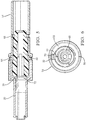
Fig. 5 is a cross section side view of the electromagnetic shield terminal assembly ofFig. 1 , according to one embodiment of the invention; -
Fig. 6 is an end view of the electromagnetic shield terminal assembly ofFig. 1 , according to one embodiment of the invention; -
Fig. 7 is a side view of an electromagnetic shield terminal assembly, according to another embodiment of the invention; -
Fig. 8 is an exploded side view of the electromagnetic shield terminal assembly ofFig. 7 , according to the another embodiment of the invention; -
Fig. 9 is a perspective view of an outer ferrule of the electromagnetic shield terminal assembly ofFig. 1 , according to yet another embodiment of the invention; and -
Fig. 10 is a perspective view of the outer ferruleFig. 9 crimped to a coaxial cable, according to the yet another embodiment of the invention. - Reference will now be made in detail to embodiments, examples of which are illustrated in the accompanying drawings. In the following detailed description, numerous specific details are set forth in order to provide a thorough understanding of the various described embodiments. However, it will be apparent to one of ordinary skill in the art that the various described embodiments may be practiced without these specific details. In other instances, well-known methods, procedures, components, circuits, and networks have not been described in detail so as not to unnecessarily obscure aspects of the embodiments.
-
Fig. 1 illustrates an embodiment of a shieldedcable assembly 10 that includes an electromagneticshield terminal assembly 14 to provide electromagnetic shielding to an electrical terminal (not shown) connected to a central conductor (not shown) of a shieldedcable 12. The central conductor is axially surrounded by an inner insulation layer (not shown), ashield conductor 16 axially surrounding the inner insulation layer and anouter insulation layer 18 axially surrounding theshield conductor 16. The shieldedcable 12 may include a single central conductor, e.g. coaxial cable, two central conductors, e.g. twinax cable, or more than two central conductors, e.g. shielded Category 6 cable. Theshield conductor 16 is terminated by the electromagneticshield terminal assembly 14. - The electromagnetic
shield terminal assembly 14 includes a tubularinner ferrule 20 shown inFig. 2 that is formed from sheet metal, e.g. by stamping or blanking operation followed by a rolling operation. Theinner ferrule 20 has aferrule seam 22 that extends longitudinally in a tortuous path along an entire length of theinner ferrule 20. Theinner ferrule 20 also has aflared attachment end 24 that is disposed under theshield conductor 16, i.e. intermediate theshield conductor 16 and the inner insulation layer. Theflare 26 of theattachment end 24 forms a projecting ridge. Alternative embodiments of the inner ferrule may be seamless and may be formed from sheet metal by a deep draw stamping process or from a billet of metal by a machining process. Theinner ferrule 20 also has aconnection end 28 that has a larger diameter than theattachment end 24 and aferrule transition segment 30 between theattachment end 24 and theconnection end 28. Theferrule seam 22 defines alongitudinal slot 32 in theconnection end 28. - The electromagnetic
shield terminal assembly 14 also includes a crimpedouter ferrule 34 illustrated inFig. 3 that is formed of sheet metal. Theouter ferrule 34 has acable attachment portion 36 that defines a pair ofbypass crimp wings 38 that surround and are in electrical contact with theshield conductor 16. Theouter ferrule 34 also has a pair ofinsulation crimp wings 40 that are attached to an end of theouter insulation layer 18 of the coaxial cable. As shown inFig. 1 , theflare 26 is located intermediate thebypass crimp wings 38 and theinsulation crimp wings 40. The location of theflare 26 between thebypass crimp wings 38 and theinsulation crimp wings 40 provides a robust mechanical stop for increased braid crimp retention. A width of the gap in theferrule seam 22 is controlled by theouter ferrule 34 when it is crimped to theinner ferrule 20. - Each of the
insulation crimp wings 40 defines a plurality of prongs 42 that have pointed ends that penetrate theouter insulation layer 18. Eachinsulation crimp wing 40 defines anupper prong 42A on afree end 44 of theinsulation crimp wing 40 and alower prong 42B located nearer abase 46 of theinsulation crimp wing 40 than theupper prong 42A. The prongs 42 are generally radially evenly spaced about the circumference of theouter insulation layer 18, i.e. the four prongs 42 are spaced such that each prong 42 is radially offset by about 90 degrees from an adjacent prong 42. The even spacing of the prongs 42 provides a more uniform distribution of puling force to resist detachment of theouter ferrule 34 from theouter insulation layer 18. The prongs 42 also maintain the grip of theouter ferrule 34 to theouter insulation layer 18 if theouter insulation layer 18 shrinks due to aging or temperature exposure. - The
cable attachment portion 36 defines a hemisphericalfirst projection 48 that contacts and indents theshield conductor 16. Each of thebypass crimp wings 38 defines a hemisphericalsecond projection 50 that contacts and indents theshield conductor 16. Thesecond projections 50 are positioned opposite thefirst projection 48. - The
cable attachment portion 36 defines a knurled pattern in an interior surface of thecable attachment portion 36. The knurled pattern includes a plurality ofindentations 52. Each indentation in the plurality ofindentations 52 has a rhomboid shape. A first pair of opposing inner corners define a generally longitudinal minor distance therebetween and a second pair of opposing inner corners different from said first pair of opposing inner corners define a major distance therebetween. The generally longitudinal minor distance is less than the major distance. - When used with a double shielded cable, i.e. a cable having a two piece shield conductor with a foil shield conductor surrounded by a braided wire shield conductor, the foil shield conductor may be disposed between the
inner ferrule 20 and the inner insulation layer and the braided wire shield conductor may be disposed between theinner ferrule 20 and theouter ferrule 34. - The electromagnetic
shield terminal assembly 14 further includes atubular shield contact 54, best shown inFigs. 4 and5 , that is electrically connected to theconnection end 28 of theinner ferrule 20 that is located opposite theattachment end 24. Theshield contact 54 is formed from sheet metal, e.g. by stamping or blanking operation followed by a rolling operation. Theshield contact 54 has acontact seam 56 that extends longitudinally along an entire length of theshield contact 54. Alternative embodiments of the shield contact may be seamless and may be formed from sheet metal by a deep draw stamping process or from a billet of metal by a machining process. Theshield contact 54 has a female receivingend 58 that is configured to receive themale connection end 28 of theinner ferrule 20 and ashield end 60 that is configured to surround and shield a terminal (not shown) attached to the inner conductor of the coaxial cable. The receiving end has a larger diameter than theshield end 60 and ashield transition segment 62 between theshield end 60 and the receiving end. The receiving end defines a first plurality ofindentations 52 projecting into the receiving end, hereinafter referred to asferrule stop 64 that limit the length of the connecting end of theinner ferrule 20 that is received within the receiving end of theshield contact 54. - The electromagnetic
shield terminal assembly 14 additionally includes atubular terminal insulator 66, best shown inFigs. 4 and5 , that is formed of a dielectric material, such as polyamide, polyethylene, polybutylene terephthalate, or another electrically insulative polymer material. Theterminal insulator 66 is disposed within theshield contact 54 and theconnection end 28 of theinner ferrule 20. Theshield end 60 of theshield contact 54 defines a second plurality ofindentations 52 projecting into theshield end 60, hereinafter referred to asterminal stop 68 that limit the length of the connecting end of theinner ferrule 20 that is received within the receiving end of theshield contact 54. The inner ferule stop andterminal stop 68 ensure proper positioning of theconnection end 28 and theterminal insulator 66 within theshield contact 54, thereby providing improved high frequency performance of the electromagneticshield terminal assembly 14. - The
terminal insulator 66 defines anorientation rib 70 that longitudinally extends along a portion of theterminal insulator 66. Theorientation rib 70 is received within the slot of theinner ferrule 20 to aid in the insertion of theterminal insulator 66 into theinner ferrule 20 and to provide proper orientation of theterminal insulator 66 within the electromagneticshield terminal assembly 14. Theterminal insulator 66 also defines a plurality ofcrush ribs 72 that are configured to contact theferrule transition segment 30. Thesecrush ribs 72 ensure that theterminal insulator 66 is properly seated within theinner ferrule 20 andshield contact 54 and inhibits movement of theterminal insulator 66 within the electromagneticshield terminal assembly 14. Proper seating of theterminal insulator 66 reduces electrical impedance fluctuations within the interface between theinner ferrule 20 and theshield contact 54. As shown inFig. 6 , theferrule seam 22 andcontact seam 56 are radially offset from one another, preferably by 180 degrees. This radial offset of theferrule seam 22 andcontact seam 56 provides increased mechanical strength and improved high frequency performance of the electromagneticshield terminal assembly 14. - The electromagnetic
shield terminal assembly 14 shown inFigs. 1-6 illustrates an embodiment of a male electromagnetic shield terminal assembly.Figs 7 and 8 illustrate an embodiment of a female electromagneticshield terminal assembly 114 having aninner ferule 120, ashield contact 154,terminal insulator 166 that is configured to mate with the electromagneticshield terminal assembly 14. -
Figs. 9 and 10 illustrate an alternative embodiment of the crimpedouter ferrule 234. Theouter ferrule 234 is formed of sheet metal. Theouter ferrule 234 has acable attachment portion 236 that defines a pair ofbypass crimp wings 238 that surround and are in electrical contact with theshield conductor 16. Theouter ferrule 234 also has a pair ofinsulation crimp wings 240 that are attached to an end of theouter insulation layer 18 of the coaxial cable. Each of theinsulation crimp wings 240 defines aprong 242 on afree end 244 of theinsulation crimp wing 240 that has a pointed end that penetrates theouter insulation layer 18. Theprongs 242 maintain the grip of theouter ferrule 234 to theouter insulation layer 18 if theouter insulation layer 18 shrinks due to aging or temperature exposure. Thecable attachment portion 236 also defines a embossed ridge orrib 274 projecting from thecable attachment portion 236 toward theshield conductor 16. Therib 274 extends laterally from oneinsulation crimp wing 240 to the otherinsulation crimp wing 240. - The
cable attachment portion 236 defines a hemisphericalfirst projection 248 that contacts and indents theshield conductor 16. Each of thebypass crimp wings 238 defines a hemisphericalsecond projection 250 that contacts and indents theshield conductor 16. Thesecond projections 250 are positioned opposite thefirst projection 248. - Although the present disclosure is not so limited, the following numbered examples demonstrate one or more aspects of the disclosure.
- Example 1. A shielded cable assembly, comprising: a shielded cable having a central conductor axially surrounded by an inner insulation layer, a shield conductor axially surrounding the inner insulation layer and an outer insulation layer axially surrounding the shield conductor; a tubular inner ferrule having a flared attachment end disposed intermediate the shield conductor and the inner insulation layer; and a crimped outer ferrule formed of sheet metal having a cable attachment portion that defines a pair of bypass crimp wings surrounding and in electrical contact with the shield conductor and having a pair of insulation crimp wings attached to an end of the outer insulation layer, wherein each insulation crimp wing defines a plurality of prongs having pointed ends that penetrate the outer insulation layer and wherein the flared attachment end of the inner ferrule is located intermediate the bypass crimp wings and the insulation crimp wings.
- Example 2. The shielded cable assembly according to example 1, further comprising a tubular shield contact electrically connected to a connection end of the inner ferrule located opposite the flared attachment end.
- Example 3. The shielded cable assembly according to example 1 or 2, wherein each of the insulation crimp wings defines an upper prong on a free end of the insulation crimp wing and a lower prong located nearer a base of the insulation crimp wing than the upper prong.
- Example 4. The shielded cable assembly according to example 1 or 2, wherein each of the insulation crimp wings defines an upper prong on a free end of the insulation crimp wing and an embossed rib extending laterally across the insulation crimp wings.
- Example 5. The shielded cable assembly according to any one of the preceding examples, wherein the cable attachment portion defines a first projection contacting and indenting the shield conductor, wherein the first projection is characterized as having a hemispherical shape.
- Example 6. The shielded cable assembly according to example 5, wherein each bypass crimp wing defines a second projection contacting and indenting the shield conductor, wherein the second projection is positioned opposite the first projection, wherein the second projection is characterized as having a hemispherical shape.
- Example 7. The shielded cable assembly according to any one of the preceding examples, wherein the inner ferrule has a seam extending longitudinally along an entire length of the inner ferrule that follows a tortuous path.
- Example 8. An electromagnetic shield terminal assembly configured for attachment to a shielded cable having a central conductor axially surrounded by an inner insulation layer, a shield conductor axially surrounding the inner insulation layer and an outer insulation layer axially surrounding the shield conductor, the electromagnetic shield terminal assembly comprising: a tubular inner ferrule having a flared attachment end configured to be disposed intermediate the shield conductor and the inner insulation layer; and a crimped outer ferrule formed of sheet metal having a cable attachment portion that defines a pair of bypass crimp wings configured to surround and be in electrical contact with the shield conductor and having a pair of insulation crimp wings configured to be attached to an end of the outer insulation layer, wherein each insulation crimp wing defines a plurality of prongs having pointed ends that are configured to penetrate the outer insulation layer and wherein the flared attachment end of the inner ferrule is configured to be located intermediate the bypass crimp wings and the insulation crimp wings when the outer ferrule is crimped to the shielded cable.
- Example 9. The electromagnetic shield terminal assembly according to example 8, further comprising a tubular shield contact electrically connected to a connection end of the inner ferrule located opposite the flared attachment end.
- Example 10. The electromagnetic shield terminal assembly according to example 8 or 9, wherein each of the insulation crimp wings defines an upper prong on a free end of the insulation crimp wing and a lower prong located nearer a base of the insulation crimp wing than the upper prong.
- Example 11. The electromagnetic shield terminal assembly according to any one of the examples 8 to 10, wherein the cable attachment portion defines a first projection configured to contact and indent the shield conductor, wherein the first projection is characterized as having a hemispherical shape.
- Example 12. The electromagnetic shield terminal assembly according to example 11, wherein each bypass crimp wing defines a second projection configured to contact and indent the shield conductor, wherein the second projection is characterized as having a hemispherical shape, wherein the second projection is positioned opposite the first projection.
- Example 13. The electromagnetic shield terminal assembly according to any one of the examples 8 to 12, wherein the inner ferrule has a seam extending longitudinally along an entire length of the inner ferrule that follows a tortuous path.
- Example 14. A shielded cable assembly, comprising: a shielded cable having a central conductor axially surrounded by an inner insulation layer, a shield conductor axially surrounding the inner insulation layer and an outer insulation layer axially surrounding the shield conductor; a tubular inner ferrule having an attachment end disposed intermediate the shield conductor and the inner insulation layer and a connection end located opposite the attachment end; a tubular shield contact electrically having a receiving end in which the connection end is disposed and a shield end located opposite the receiving end, said shield contact defining a first plurality of indentations in the receiving end and a second plurality of indentations in the shield end, wherein the connection end is in contact with the first plurality of indentations; and a tubular terminal insulator disposed within the connection end and the receiving end, wherein the terminal insulator is in contact with the second plurality of indentations.
- Example 15. The shielded cable assembly according to example 14, wherein the connection end defines a longitudinal slot and the terminal insulator defines a longitudinal orientation rib and wherein the orientation rib is disposed within the slot..
- Example 16. The shielded cable assembly according to example 14 or 15, wherein the connection end has a larger diameter than the attachment end and the inner ferrule defines a ferrule transition segment between the connection end and the attachment end and wherein the terminal insulator defines a plurality of crush ribs that are in contact with and deformed by the ferrule transition segment.
- Example 17. The shielded cable assembly according to any one of the examples 14 to 16, wherein the inner ferrule has a ferrule seam extending longitudinally along an entire length of the inner ferrule and the shield contact has a contact seam extending longitudinally along an entire length of the shield contact and wherein the ferrule seam and the contact seam are radially offset from one another.
- Example 18. The shielded cable assembly according to example 17, wherein the ferrule seam and the contact seam are radially offset from one another by 180 degrees.
- Example 19. An electromagnetic shield terminal assembly configured for attachment to a shielded cable having a central conductor axially surrounded by an inner insulation layer, a shield conductor axially surrounding the inner insulation layer and an outer insulation layer axially surrounding the shield conductor, the electromagnetic shield terminal assembly comprising: a tubular inner ferrule having an attachment end configured to be disposed intermediate the shield conductor and the inner insulation layer and a connection end located opposite the attachment end; a tubular shield contact electrically having a receiving end in which the connection end is disposed and a shield end located opposite the receiving end, said shield contact defining a first plurality of indentations in the receiving end and a second plurality of indentations in the shield end, wherein the connection end is in contact with the first plurality of indentations; and a tubular terminal insulator disposed within the connection end and the receiving end, wherein the terminal insulator is in contact with the second plurality of indentations.
- Example 20. The electromagnetic shield terminal assembly according to example 19, wherein the connection end defines a longitudinal slot and the terminal insulator defines a longitudinal orientation rib and wherein the orientation rib is disposed within the slot.
- Example 21. The electromagnetic shield terminal assembly according to example 19 or 20, wherein the connection end has a larger diameter than the attachment end and the inner ferrule defines a ferrule transition segment between the connection end and the attachment end and wherein the terminal insulator defines a plurality of crush ribs that are in contact with and deformed by the ferrule transition segment.
- Example 22. The electromagnetic shield terminal assembly according to any one of the examples 19 to 21, wherein the inner ferrule has a ferrule seam extending longitudinally along an entire length of the inner ferrule and the shield contact has a contact seam extending longitudinally along an entire length of the shield contact and wherein the ferrule seam and the contact seam are radially offset from one another.
- Example 23. The electromagnetic shield terminal assembly according to example 22, wherein the ferrule seam and the contact seam are radially offset from one another by 180 degrees.
- While this invention has been described in terms of the preferred embodiments thereof, it is not intended to be so limited, but rather only to the extent set forth in the claims that follow. For example, the above-described embodiments (and/or aspects thereof) may be used in combination with each other. In addition, many modifications may be made to configure a particular situation or material to the teachings of the invention without departing from its scope. Dimensions, types of materials, orientations of the various components, and the number and positions of the various components described herein are intended to define parameters of certain embodiments, and are by no means limiting and are merely prototypical embodiments.
- Many other embodiments and modifications within the spirit and scope of the claims will be apparent to those of skill in the art upon reviewing the above description. The scope of the invention should, therefore, be determined with reference to the following claims, along with the full scope of equivalents to which such claims are entitled.
- As used herein, 'one or more' includes a function being performed by one element, a function being performed by more than one element, e.g., in a distributed fashion, several functions being performed by one element, several functions being performed by several elements, or any combination of the above.
- It will also be understood that, although the terms first, second, etc. are, in some instances, used herein to describe various elements, these elements should not be limited by these terms. These terms are only used to distinguish one element from another. For example, a first contact could be termed a second contact, and, similarly, a second contact could be termed a first contact, without departing from the scope of the various described embodiments. The first contact and the second contact are both contacts, but they are not the same contact.
- The terminology used in the description of the various described embodiments herein is for the purpose of describing particular embodiments only and is not intended to be limiting. As used in the description of the various described embodiments and the appended claims, the singular forms "a", "an" and "the" are intended to include the plural forms as well, unless the context clearly indicates otherwise. It will also be understood that the term "and/or" as used herein refers to and encompasses any and all possible combinations of one or more of the associated listed items. It will be further understood that the terms "includes," "including," "comprises," and/or "comprising," when used in this specification, specify the presence of stated features, integers, steps, operations, elements, and/or components, but do not preclude the presence or addition of one or more other features, integers, steps, operations, elements, components, and/or groups thereof.
- As used herein, the term "if' is, optionally, construed to mean "when" or "upon" or "in response to determining" or "in response to detecting," depending on the context. Similarly, the phrase "if it is determined" or "if [a stated condition or event] is detected" is, optionally, construed to mean "upon determining" or "in response to determining" or "upon detecting [the stated condition or event]" or "in response to detecting [the stated condition or event]," depending on the context.
- Additionally, while terms of ordinance or orientation may be used herein these elements should not be limited by these terms. All terms of ordinance or orientation, unless stated otherwise, are used for purposes distinguishing one element from another, and do not denote any particular order, order of operations, direction or orientation unless stated otherwise.
Claims (13)
- A shielded cable assembly, comprising:a shielded cable having a central conductor axially surrounded by an inner insulation layer, a shield conductor axially surrounding the inner insulation layer and an outer insulation layer axially surrounding the shield conductor;a tubular inner ferrule having a flared attachment end disposed intermediate the shield conductor and the inner insulation layer; anda crimped outer ferrule formed of sheet metal having a cable attachment portion that defines a pair of bypass crimp wings surrounding and in electrical contact with the shield conductor and having a pair of insulation crimp wings attached to an end of the outer insulation layer, wherein each insulation crimp wing defines a plurality of prongs having pointed ends that penetrate the outer insulation layer and wherein the flared attachment end of the inner ferrule is located intermediate the bypass crimp wings and the insulation crimp wings.
- The shielded cable assembly according to claim 1, further comprising a tubular shield contact electrically connected to a connection end of the inner ferrule located opposite the flared attachment end.
- The shielded cable assembly according to claim 1 or 2, wherein each of the insulation crimp wings defines an upper prong on a free end of the insulation crimp wing and a lower prong located nearer a base of the insulation crimp wing than the upper prong.
- The shielded cable assembly according to claim 1 or 2, wherein each of the insulation crimp wings defines an upper prong on a free end of the insulation crimp wing and an embossed rib extending laterally across the insulation crimp wings.
- The shielded cable assembly according to any one of the preceding claims, wherein the cable attachment portion defines a first projection contacting and indenting the shield conductor, wherein the first projection is characterized as having a hemispherical shape.
- The shielded cable assembly according to claim 5, wherein each bypass crimp wing defines a second projection contacting and indenting the shield conductor, wherein the second projection is positioned opposite the first projection, wherein the second projection is characterized as having a hemispherical shape.
- The shielded cable assembly according to any one of the preceding claims, wherein the inner ferrule has a seam extending longitudinally along an entire length of the inner ferrule that follows a tortuous path.
- An electromagnetic shield terminal assembly configured for attachment to a shielded cable having a central conductor axially surrounded by an inner insulation layer, a shield conductor axially surrounding the inner insulation layer and an outer insulation layer axially surrounding the shield conductor, the electromagnetic shield terminal assembly comprising:a tubular inner ferrule having a flared attachment end configured to be disposed intermediate the shield conductor and the inner insulation layer; anda crimped outer ferrule formed of sheet metal having a cable attachment portion that defines a pair of bypass crimp wings configured to surround and be in electrical contact with the shield conductor and having a pair of insulation crimp wings configured to be attached to an end of the outer insulation layer, wherein each insulation crimp wing defines a plurality of prongs having pointed ends that are configured to penetrate the outer insulation layer and wherein the flared attachment end of the inner ferrule is configured to be located intermediate the bypass crimp wings and the insulation crimp wings when the outer ferrule is crimped to the shielded cable.
- The electromagnetic shield terminal assembly according to claim 8, further comprising a tubular shield contact electrically connected to a connection end of the inner ferrule located opposite the flared attachment end.
- The electromagnetic shield terminal assembly according to claim 8 or 9, wherein each of the insulation crimp wings defines an upper prong on a free end of the insulation crimp wing and a lower prong located nearer a base of the insulation crimp wing than the upper prong.
- The electromagnetic shield terminal assembly according to any one of the claims 8 to 10, wherein the cable attachment portion defines a first projection configured to contact and indent the shield conductor, wherein the first projection is characterized as having a hemispherical shape.
- The electromagnetic shield terminal assembly according to claim 11, wherein each bypass crimp wing defines a second projection configured to contact and indent the shield conductor, wherein the second projection is characterized as having a hemispherical shape, wherein the second projection is positioned opposite the first projection.
- The electromagnetic shield terminal assembly according to any one of the claims 8 to 12, wherein the inner ferrule has a seam extending longitudinally along an entire length of the inner ferrule that follows a tortuous path.
Applications Claiming Priority (2)
| Application Number | Priority Date | Filing Date | Title |
|---|---|---|---|
| US201862747820P | 2018-10-19 | 2018-10-19 | |
| US16/567,384 US10741975B2 (en) | 2018-10-19 | 2019-09-11 | Sheilded cable assembly and electromagnetic shield terminal assembly for same |
Publications (2)
| Publication Number | Publication Date |
|---|---|
| EP3641061A1 true EP3641061A1 (en) | 2020-04-22 |
| EP3641061B1 EP3641061B1 (en) | 2023-05-31 |
Family
ID=68281140
Family Applications (1)
| Application Number | Title | Priority Date | Filing Date |
|---|---|---|---|
| EP19203503.8A Active EP3641061B1 (en) | 2018-10-19 | 2019-10-16 | Shielded cable assembly |
Country Status (4)
| Country | Link |
|---|---|
| US (1) | US10741975B2 (en) |
| EP (1) | EP3641061B1 (en) |
| KR (1) | KR102293142B1 (en) |
| CN (1) | CN111082235B (en) |
Cited By (2)
| Publication number | Priority date | Publication date | Assignee | Title |
|---|---|---|---|---|
| US11637388B2 (en) * | 2021-09-17 | 2023-04-25 | Aptiv Technologies Limited | Ferrule for a coaxial cable terminal having overlapping crimp wings |
| EP4386995A1 (en) * | 2022-12-12 | 2024-06-19 | Aptiv Technologies (2) S.à r.l. | Coaxial electrical terminal with crimped outer ferrule |
Families Citing this family (14)
| Publication number | Priority date | Publication date | Assignee | Title |
|---|---|---|---|---|
| JP7380420B2 (en) * | 2020-05-27 | 2023-11-15 | 株式会社オートネットワーク技術研究所 | shield conductive path |
| US11848120B2 (en) | 2020-06-05 | 2023-12-19 | Pct International, Inc. | Quad-shield cable |
| TW202203259A (en) * | 2020-06-05 | 2022-01-16 | 美商Pct國際有限公司 | Quad-shield cable |
| US11469557B2 (en) * | 2020-07-28 | 2022-10-11 | Aptiv Technologies Limited | Coaxial electrical connector |
| CN112133503A (en) * | 2020-10-16 | 2020-12-25 | 广东立胜电力技术有限公司 | Strain insulator pole insulator shields cover |
| JP7339235B2 (en) * | 2020-10-23 | 2023-09-05 | 矢崎総業株式会社 | high frequency connector |
| DE102021127231A1 (en) * | 2020-10-23 | 2022-04-28 | Yazaki Corporation | high frequency connector |
| FR3117690B1 (en) * | 2020-12-11 | 2025-06-20 | Aptiv Tech Ltd | assembly of an electric cable with a cable terminal |
| US11646510B2 (en) | 2021-04-29 | 2023-05-09 | Aptiv Technologies Limited | Shielding electrical terminal with knurling on inner contact walls |
| JP7533384B2 (en) * | 2021-07-07 | 2024-08-14 | 株式会社オートネットワーク技術研究所 | Shield Conductive Path |
| JP2023068262A (en) * | 2021-11-02 | 2023-05-17 | I-Pex株式会社 | Terminal and connector |
| US12244114B2 (en) * | 2021-11-16 | 2025-03-04 | Te Connectivity Solutions Gmbh | High deformation and retention ferrule |
| US11824319B2 (en) | 2022-02-10 | 2023-11-21 | Aptiv Technologies AG | Electrical cable terminal with two piece coaxial crimped outer ferrule |
| CN117038186B (en) * | 2023-07-19 | 2024-03-26 | 安徽天康集团数据线缆有限公司 | Underwater waterproof data cable |
Citations (3)
| Publication number | Priority date | Publication date | Assignee | Title |
|---|---|---|---|---|
| EP1005106A2 (en) * | 1998-11-27 | 2000-05-31 | Sumitomo Wiring Systems, Ltd. | Terminal and crimping method |
| US20120202372A1 (en) * | 2011-02-04 | 2012-08-09 | Tyco Electronics Amp Gmbh | Connector assembly |
| US9673578B1 (en) * | 2016-05-06 | 2017-06-06 | Te Connectivity Corporation | Cable-mounted electrical connector |
Family Cites Families (20)
| Publication number | Priority date | Publication date | Assignee | Title |
|---|---|---|---|---|
| US6210223B1 (en) * | 1998-11-19 | 2001-04-03 | Sumitomo Wiring Systems, Ltd. | Shielded connector, a set of shielded connectors and method for connecting a shielded connector with a shielded cable |
| JP4298732B2 (en) * | 2006-09-07 | 2009-07-22 | 日本航空電子工業株式会社 | connector |
| JP2009099266A (en) * | 2007-10-12 | 2009-05-07 | Yazaki Corp | Shield terminal for coaxial cable |
| US7794274B2 (en) | 2008-07-30 | 2010-09-14 | Delphi Technologies, Inc. | RF connector with integrated shield |
| JP2012009229A (en) * | 2010-06-23 | 2012-01-12 | Jst Mfg Co Ltd | Contact for coaxial cable and terminal processing method |
| JP5711571B2 (en) * | 2011-03-02 | 2015-05-07 | 矢崎総業株式会社 | Coaxial cable terminal processing structure and terminal processing method |
| DE102011076881A1 (en) * | 2011-06-01 | 2012-12-06 | Tyco Electronics Amp Gmbh | CONTACT COMBINATION APPARATUS, METHOD FOR PRODUCING AND / OR FITTING AN ELECTRICAL CONNECTING DEVICE, ELECTRICAL CONNECTING DEVICE AND ELECTRICAL CONNECTOR |
| US8485853B2 (en) * | 2011-11-03 | 2013-07-16 | Delphi Technologies, Inc. | Electrical contact having knurl pattern with recessed rhombic elements that each have an axial minor distance |
| DE102011056798B4 (en) * | 2011-12-21 | 2013-07-25 | Phoenix Contact Gmbh & Co. Kg | Shielded connector and method of making a shielded connector |
| US9537231B2 (en) * | 2014-11-12 | 2017-01-03 | Tyco Electronics Corporation | Connector assembly |
| JP6404867B2 (en) * | 2016-01-12 | 2018-10-17 | 矢崎総業株式会社 | Shield connector |
| US9960504B2 (en) * | 2016-01-12 | 2018-05-01 | Yazaki Corporation | Shielded connector |
| US9762001B2 (en) | 2016-02-01 | 2017-09-12 | Delphi Technologies, Inc. | Right angled coaxial electrical connector and methods for verifying proper assembly thereof |
| EP3203586B1 (en) * | 2016-02-02 | 2020-07-22 | Yazaki Europe Ltd | Electrical connector |
| EP3220483A1 (en) * | 2016-03-17 | 2017-09-20 | TE Connectivity Germany GmbH | Electric connection device, method of assembling an electrical cable and assembled electrical coaxial cable |
| US9667000B1 (en) | 2016-06-09 | 2017-05-30 | Delphi Technologies, Inc. | Radio frequency coaxial connector assembly and method of manufacturing same |
| US9960550B2 (en) | 2016-07-25 | 2018-05-01 | Delphi Technologies, Inc. | Coaxial connector assembly |
| US9929519B1 (en) * | 2016-09-22 | 2018-03-27 | Te Connectivity Corporation | Electrical cable connector and method of assembling the same |
| US10008786B2 (en) | 2016-10-28 | 2018-06-26 | Delphi Technologies, Inc. | Coaxial-cable-assembly, ferrule, and method of making the same |
| US10446950B2 (en) | 2017-06-26 | 2019-10-15 | Delphi Technologies, Llc | Method for forming a shielded electrical terminal and an electrical terminal formed by said method |
-
2019
- 2019-09-11 US US16/567,384 patent/US10741975B2/en active Active
- 2019-09-26 CN CN201910916841.XA patent/CN111082235B/en active Active
- 2019-10-15 KR KR1020190127424A patent/KR102293142B1/en active Active
- 2019-10-16 EP EP19203503.8A patent/EP3641061B1/en active Active
Patent Citations (3)
| Publication number | Priority date | Publication date | Assignee | Title |
|---|---|---|---|---|
| EP1005106A2 (en) * | 1998-11-27 | 2000-05-31 | Sumitomo Wiring Systems, Ltd. | Terminal and crimping method |
| US20120202372A1 (en) * | 2011-02-04 | 2012-08-09 | Tyco Electronics Amp Gmbh | Connector assembly |
| US9673578B1 (en) * | 2016-05-06 | 2017-06-06 | Te Connectivity Corporation | Cable-mounted electrical connector |
Cited By (2)
| Publication number | Priority date | Publication date | Assignee | Title |
|---|---|---|---|---|
| US11637388B2 (en) * | 2021-09-17 | 2023-04-25 | Aptiv Technologies Limited | Ferrule for a coaxial cable terminal having overlapping crimp wings |
| EP4386995A1 (en) * | 2022-12-12 | 2024-06-19 | Aptiv Technologies (2) S.à r.l. | Coaxial electrical terminal with crimped outer ferrule |
Also Published As
| Publication number | Publication date |
|---|---|
| US20200127421A1 (en) | 2020-04-23 |
| EP3641061B1 (en) | 2023-05-31 |
| CN111082235B (en) | 2022-03-01 |
| CN111082235A (en) | 2020-04-28 |
| KR20200045406A (en) | 2020-05-04 |
| US10741975B2 (en) | 2020-08-11 |
| KR102293142B1 (en) | 2021-08-26 |
Similar Documents
| Publication | Publication Date | Title |
|---|---|---|
| US10741975B2 (en) | Sheilded cable assembly and electromagnetic shield terminal assembly for same | |
| EP3787125B1 (en) | Shielded electrical connector assembly and manufacturing method thereof | |
| EP2019459B1 (en) | High performance coaxial connector | |
| EP1701410B1 (en) | Coaxial connector with a cable gripping feature | |
| US8992258B2 (en) | Electrical cable connector shield with positive retention locking feature | |
| US20050266727A1 (en) | Coaxial cable shielding terminal | |
| EP3175512B1 (en) | Coaxial cable connectors with conductor retaining members | |
| JP2018026323A (en) | Radio frequency coaxial connector assembly and method of manufacturing the assembly | |
| US10008786B2 (en) | Coaxial-cable-assembly, ferrule, and method of making the same | |
| US11469557B2 (en) | Coaxial electrical connector | |
| EP3547454A1 (en) | Conductor assembly with a crimped tubular ferrule and method of manufacturing same | |
| EP3569326A1 (en) | Ferrule crimping tool | |
| US10497492B2 (en) | Terminal and cable with terminal | |
| US11742111B2 (en) | End structure and sleeve of shielded cable | |
| WO2019011754A1 (en) | Receptacle connector and method of pluging plug connector | |
| JP2006024499A (en) | Connector for coaxial cable | |
| US11462342B2 (en) | Cable harness assembly with a shielded twisted pair cable | |
| CN220042347U (en) | Connector terminal, terminal assembly, connector and connector assembly | |
| US20260045707A1 (en) | Electrical cable terminal with crimping wings | |
| EP4386995A1 (en) | Coaxial electrical terminal with crimped outer ferrule | |
| JPH0654266U (en) | Center contact for coaxial connector |
Legal Events
| Date | Code | Title | Description |
|---|---|---|---|
| PUAI | Public reference made under article 153(3) epc to a published international application that has entered the european phase |
Free format text: ORIGINAL CODE: 0009012 |
|
| STAA | Information on the status of an ep patent application or granted ep patent |
Free format text: STATUS: THE APPLICATION HAS BEEN PUBLISHED |
|
| AK | Designated contracting states |
Kind code of ref document: A1 Designated state(s): AL AT BE BG CH CY CZ DE DK EE ES FI FR GB GR HR HU IE IS IT LI LT LU LV MC MK MT NL NO PL PT RO RS SE SI SK SM TR |
|
| AX | Request for extension of the european patent |
Extension state: BA ME |
|
| STAA | Information on the status of an ep patent application or granted ep patent |
Free format text: STATUS: REQUEST FOR EXAMINATION WAS MADE |
|
| 17P | Request for examination filed |
Effective date: 20201001 |
|
| RBV | Designated contracting states (corrected) |
Designated state(s): AL AT BE BG CH CY CZ DE DK EE ES FI FR GB GR HR HU IE IS IT LI LT LU LV MC MK MT NL NO PL PT RO RS SE SI SK SM TR |
|
| RIN1 | Information on inventor provided before grant (corrected) |
Inventor name: DEMONICA, MICHAEL J. Inventor name: MESSURI, MICHAEL D. Inventor name: SCHUSTER, JAMES P. Inventor name: LIPTAK, NICOLE L. Inventor name: MARGRAVE, CHRISTOPHER A. Inventor name: MESSURI, DOMINIC A. Inventor name: BILAS, JARED Inventor name: JONES, LESLIE L. |
|
| STAA | Information on the status of an ep patent application or granted ep patent |
Free format text: STATUS: EXAMINATION IS IN PROGRESS |
|
| 17Q | First examination report despatched |
Effective date: 20210924 |
|
| GRAP | Despatch of communication of intention to grant a patent |
Free format text: ORIGINAL CODE: EPIDOSNIGR1 |
|
| STAA | Information on the status of an ep patent application or granted ep patent |
Free format text: STATUS: GRANT OF PATENT IS INTENDED |
|
| RAP3 | Party data changed (applicant data changed or rights of an application transferred) |
Owner name: APTIV TECHNOLOGIES LIMITED |
|
| RIC1 | Information provided on ipc code assigned before grant |
Ipc: H01R 103/00 20060101ALN20230223BHEP Ipc: H01R 4/20 20060101ALI20230223BHEP Ipc: H01R 13/58 20060101ALI20230223BHEP Ipc: H01R 9/053 20060101ALI20230223BHEP Ipc: H01R 9/05 20060101ALI20230223BHEP Ipc: H01R 4/18 20060101AFI20230223BHEP |
|
| INTG | Intention to grant announced |
Effective date: 20230320 |
|
| GRAS | Grant fee paid |
Free format text: ORIGINAL CODE: EPIDOSNIGR3 |
|
| GRAA | (expected) grant |
Free format text: ORIGINAL CODE: 0009210 |
|
| STAA | Information on the status of an ep patent application or granted ep patent |
Free format text: STATUS: THE PATENT HAS BEEN GRANTED |
|
| AK | Designated contracting states |
Kind code of ref document: B1 Designated state(s): AL AT BE BG CH CY CZ DE DK EE ES FI FR GB GR HR HU IE IS IT LI LT LU LV MC MK MT NL NO PL PT RO RS SE SI SK SM TR |
|
| REG | Reference to a national code |
Ref country code: GB Ref legal event code: FG4D Ref country code: CH Ref legal event code: EP |
|
| P01 | Opt-out of the competence of the unified patent court (upc) registered |
Effective date: 20230426 |
|
| REG | Reference to a national code |
Ref country code: AT Ref legal event code: REF Ref document number: 1571527 Country of ref document: AT Kind code of ref document: T Effective date: 20230615 Ref country code: DE Ref legal event code: R096 Ref document number: 602019029491 Country of ref document: DE |
|
| REG | Reference to a national code |
Ref country code: IE Ref legal event code: FG4D |
|
| REG | Reference to a national code |
Ref country code: LT Ref legal event code: MG9D |
|
| REG | Reference to a national code |
Ref country code: NL Ref legal event code: MP Effective date: 20230531 |
|
| REG | Reference to a national code |
Ref country code: AT Ref legal event code: MK05 Ref document number: 1571527 Country of ref document: AT Kind code of ref document: T Effective date: 20230531 |
|
| PG25 | Lapsed in a contracting state [announced via postgrant information from national office to epo] |
Ref country code: SE Free format text: LAPSE BECAUSE OF FAILURE TO SUBMIT A TRANSLATION OF THE DESCRIPTION OR TO PAY THE FEE WITHIN THE PRESCRIBED TIME-LIMIT Effective date: 20230531 Ref country code: NO Free format text: LAPSE BECAUSE OF FAILURE TO SUBMIT A TRANSLATION OF THE DESCRIPTION OR TO PAY THE FEE WITHIN THE PRESCRIBED TIME-LIMIT Effective date: 20230831 Ref country code: ES Free format text: LAPSE BECAUSE OF FAILURE TO SUBMIT A TRANSLATION OF THE DESCRIPTION OR TO PAY THE FEE WITHIN THE PRESCRIBED TIME-LIMIT Effective date: 20230531 Ref country code: AT Free format text: LAPSE BECAUSE OF FAILURE TO SUBMIT A TRANSLATION OF THE DESCRIPTION OR TO PAY THE FEE WITHIN THE PRESCRIBED TIME-LIMIT Effective date: 20230531 |
|
| PG25 | Lapsed in a contracting state [announced via postgrant information from national office to epo] |
Ref country code: RS Free format text: LAPSE BECAUSE OF FAILURE TO SUBMIT A TRANSLATION OF THE DESCRIPTION OR TO PAY THE FEE WITHIN THE PRESCRIBED TIME-LIMIT Effective date: 20230531 Ref country code: PL Free format text: LAPSE BECAUSE OF FAILURE TO SUBMIT A TRANSLATION OF THE DESCRIPTION OR TO PAY THE FEE WITHIN THE PRESCRIBED TIME-LIMIT Effective date: 20230531 Ref country code: NL Free format text: LAPSE BECAUSE OF FAILURE TO SUBMIT A TRANSLATION OF THE DESCRIPTION OR TO PAY THE FEE WITHIN THE PRESCRIBED TIME-LIMIT Effective date: 20230531 Ref country code: LV Free format text: LAPSE BECAUSE OF FAILURE TO SUBMIT A TRANSLATION OF THE DESCRIPTION OR TO PAY THE FEE WITHIN THE PRESCRIBED TIME-LIMIT Effective date: 20230531 Ref country code: LT Free format text: LAPSE BECAUSE OF FAILURE TO SUBMIT A TRANSLATION OF THE DESCRIPTION OR TO PAY THE FEE WITHIN THE PRESCRIBED TIME-LIMIT Effective date: 20230531 Ref country code: IS Free format text: LAPSE BECAUSE OF FAILURE TO SUBMIT A TRANSLATION OF THE DESCRIPTION OR TO PAY THE FEE WITHIN THE PRESCRIBED TIME-LIMIT Effective date: 20230930 Ref country code: HR Free format text: LAPSE BECAUSE OF FAILURE TO SUBMIT A TRANSLATION OF THE DESCRIPTION OR TO PAY THE FEE WITHIN THE PRESCRIBED TIME-LIMIT Effective date: 20230531 Ref country code: GR Free format text: LAPSE BECAUSE OF FAILURE TO SUBMIT A TRANSLATION OF THE DESCRIPTION OR TO PAY THE FEE WITHIN THE PRESCRIBED TIME-LIMIT Effective date: 20230901 |
|
| PG25 | Lapsed in a contracting state [announced via postgrant information from national office to epo] |
Ref country code: FI Free format text: LAPSE BECAUSE OF FAILURE TO SUBMIT A TRANSLATION OF THE DESCRIPTION OR TO PAY THE FEE WITHIN THE PRESCRIBED TIME-LIMIT Effective date: 20230531 |
|
| PG25 | Lapsed in a contracting state [announced via postgrant information from national office to epo] |
Ref country code: SK Free format text: LAPSE BECAUSE OF FAILURE TO SUBMIT A TRANSLATION OF THE DESCRIPTION OR TO PAY THE FEE WITHIN THE PRESCRIBED TIME-LIMIT Effective date: 20230531 |
|
| PG25 | Lapsed in a contracting state [announced via postgrant information from national office to epo] |
Ref country code: SM Free format text: LAPSE BECAUSE OF FAILURE TO SUBMIT A TRANSLATION OF THE DESCRIPTION OR TO PAY THE FEE WITHIN THE PRESCRIBED TIME-LIMIT Effective date: 20230531 Ref country code: SK Free format text: LAPSE BECAUSE OF FAILURE TO SUBMIT A TRANSLATION OF THE DESCRIPTION OR TO PAY THE FEE WITHIN THE PRESCRIBED TIME-LIMIT Effective date: 20230531 Ref country code: RO Free format text: LAPSE BECAUSE OF FAILURE TO SUBMIT A TRANSLATION OF THE DESCRIPTION OR TO PAY THE FEE WITHIN THE PRESCRIBED TIME-LIMIT Effective date: 20230531 Ref country code: PT Free format text: LAPSE BECAUSE OF FAILURE TO SUBMIT A TRANSLATION OF THE DESCRIPTION OR TO PAY THE FEE WITHIN THE PRESCRIBED TIME-LIMIT Effective date: 20231002 Ref country code: EE Free format text: LAPSE BECAUSE OF FAILURE TO SUBMIT A TRANSLATION OF THE DESCRIPTION OR TO PAY THE FEE WITHIN THE PRESCRIBED TIME-LIMIT Effective date: 20230531 Ref country code: DK Free format text: LAPSE BECAUSE OF FAILURE TO SUBMIT A TRANSLATION OF THE DESCRIPTION OR TO PAY THE FEE WITHIN THE PRESCRIBED TIME-LIMIT Effective date: 20230531 Ref country code: CZ Free format text: LAPSE BECAUSE OF FAILURE TO SUBMIT A TRANSLATION OF THE DESCRIPTION OR TO PAY THE FEE WITHIN THE PRESCRIBED TIME-LIMIT Effective date: 20230531 |
|
| REG | Reference to a national code |
Ref country code: DE Ref legal event code: R097 Ref document number: 602019029491 Country of ref document: DE |
|
| PLBE | No opposition filed within time limit |
Free format text: ORIGINAL CODE: 0009261 |
|
| STAA | Information on the status of an ep patent application or granted ep patent |
Free format text: STATUS: NO OPPOSITION FILED WITHIN TIME LIMIT |
|
| PG25 | Lapsed in a contracting state [announced via postgrant information from national office to epo] |
Ref country code: SI Free format text: LAPSE BECAUSE OF FAILURE TO SUBMIT A TRANSLATION OF THE DESCRIPTION OR TO PAY THE FEE WITHIN THE PRESCRIBED TIME-LIMIT Effective date: 20230531 |
|
| 26N | No opposition filed |
Effective date: 20240301 |
|
| PG25 | Lapsed in a contracting state [announced via postgrant information from national office to epo] |
Ref country code: SI Free format text: LAPSE BECAUSE OF FAILURE TO SUBMIT A TRANSLATION OF THE DESCRIPTION OR TO PAY THE FEE WITHIN THE PRESCRIBED TIME-LIMIT Effective date: 20230531 Ref country code: IT Free format text: LAPSE BECAUSE OF FAILURE TO SUBMIT A TRANSLATION OF THE DESCRIPTION OR TO PAY THE FEE WITHIN THE PRESCRIBED TIME-LIMIT Effective date: 20230531 Ref country code: MC Free format text: LAPSE BECAUSE OF FAILURE TO SUBMIT A TRANSLATION OF THE DESCRIPTION OR TO PAY THE FEE WITHIN THE PRESCRIBED TIME-LIMIT Effective date: 20230531 |
|
| REG | Reference to a national code |
Ref country code: CH Ref legal event code: PL |
|
| REG | Reference to a national code |
Ref country code: BE Ref legal event code: MM Effective date: 20231031 |
|
| PG25 | Lapsed in a contracting state [announced via postgrant information from national office to epo] |
Ref country code: LU Free format text: LAPSE BECAUSE OF NON-PAYMENT OF DUE FEES Effective date: 20231016 |
|
| PG25 | Lapsed in a contracting state [announced via postgrant information from national office to epo] |
Ref country code: LU Free format text: LAPSE BECAUSE OF NON-PAYMENT OF DUE FEES Effective date: 20231016 |
|
| PG25 | Lapsed in a contracting state [announced via postgrant information from national office to epo] |
Ref country code: CH Free format text: LAPSE BECAUSE OF NON-PAYMENT OF DUE FEES Effective date: 20231031 |
|
| PG25 | Lapsed in a contracting state [announced via postgrant information from national office to epo] |
Ref country code: CH Free format text: LAPSE BECAUSE OF NON-PAYMENT OF DUE FEES Effective date: 20231031 |
|
| PG25 | Lapsed in a contracting state [announced via postgrant information from national office to epo] |
Ref country code: BE Free format text: LAPSE BECAUSE OF NON-PAYMENT OF DUE FEES Effective date: 20231031 |
|
| PG25 | Lapsed in a contracting state [announced via postgrant information from national office to epo] |
Ref country code: IE Free format text: LAPSE BECAUSE OF NON-PAYMENT OF DUE FEES Effective date: 20231016 |
|
| PG25 | Lapsed in a contracting state [announced via postgrant information from national office to epo] |
Ref country code: IE Free format text: LAPSE BECAUSE OF NON-PAYMENT OF DUE FEES Effective date: 20231016 |
|
| PG25 | Lapsed in a contracting state [announced via postgrant information from national office to epo] |
Ref country code: BG Free format text: LAPSE BECAUSE OF FAILURE TO SUBMIT A TRANSLATION OF THE DESCRIPTION OR TO PAY THE FEE WITHIN THE PRESCRIBED TIME-LIMIT Effective date: 20230531 |
|
| PG25 | Lapsed in a contracting state [announced via postgrant information from national office to epo] |
Ref country code: BG Free format text: LAPSE BECAUSE OF FAILURE TO SUBMIT A TRANSLATION OF THE DESCRIPTION OR TO PAY THE FEE WITHIN THE PRESCRIBED TIME-LIMIT Effective date: 20230531 |
|
| REG | Reference to a national code |
Ref country code: DE Ref legal event code: R081 Ref document number: 602019029491 Country of ref document: DE Owner name: APTIV TECHNOLOGIES AG, CH Free format text: FORMER OWNER: APTIV TECHNOLOGIES LIMITED, ST. MICHAEL, BB |
|
| PG25 | Lapsed in a contracting state [announced via postgrant information from national office to epo] |
Ref country code: CY Free format text: LAPSE BECAUSE OF FAILURE TO SUBMIT A TRANSLATION OF THE DESCRIPTION OR TO PAY THE FEE WITHIN THE PRESCRIBED TIME-LIMIT; INVALID AB INITIO Effective date: 20191016 |
|
| PG25 | Lapsed in a contracting state [announced via postgrant information from national office to epo] |
Ref country code: HU Free format text: LAPSE BECAUSE OF FAILURE TO SUBMIT A TRANSLATION OF THE DESCRIPTION OR TO PAY THE FEE WITHIN THE PRESCRIBED TIME-LIMIT; INVALID AB INITIO Effective date: 20191016 |
|
| PG25 | Lapsed in a contracting state [announced via postgrant information from national office to epo] |
Ref country code: TR Free format text: LAPSE BECAUSE OF FAILURE TO SUBMIT A TRANSLATION OF THE DESCRIPTION OR TO PAY THE FEE WITHIN THE PRESCRIBED TIME-LIMIT Effective date: 20230531 |
|
| PGFP | Annual fee paid to national office [announced via postgrant information from national office to epo] |
Ref country code: DE Payment date: 20250917 Year of fee payment: 7 |
|
| PGFP | Annual fee paid to national office [announced via postgrant information from national office to epo] |
Ref country code: GB Payment date: 20251015 Year of fee payment: 7 |
|
| PGFP | Annual fee paid to national office [announced via postgrant information from national office to epo] |
Ref country code: FR Payment date: 20251014 Year of fee payment: 7 |