EP3640681B1 - Method and apparatus for estimating position - Google Patents
Method and apparatus for estimating position Download PDFInfo
- Publication number
- EP3640681B1 EP3640681B1 EP19167656.8A EP19167656A EP3640681B1 EP 3640681 B1 EP3640681 B1 EP 3640681B1 EP 19167656 A EP19167656 A EP 19167656A EP 3640681 B1 EP3640681 B1 EP 3640681B1
- Authority
- EP
- European Patent Office
- Prior art keywords
- reference point
- rotation reference
- rotation
- target
- parameter
- Prior art date
- Legal status (The legal status is an assumption and is not a legal conclusion. Google has not performed a legal analysis and makes no representation as to the accuracy of the status listed.)
- Active
Links
Images








Classifications
-
- G—PHYSICS
- G01—MEASURING; TESTING
- G01S—RADIO DIRECTION-FINDING; RADIO NAVIGATION; DETERMINING DISTANCE OR VELOCITY BY USE OF RADIO WAVES; LOCATING OR PRESENCE-DETECTING BY USE OF THE REFLECTION OR RERADIATION OF RADIO WAVES; ANALOGOUS ARRANGEMENTS USING OTHER WAVES
- G01S19/00—Satellite radio beacon positioning systems; Determining position, velocity or attitude using signals transmitted by such systems
- G01S19/38—Determining a navigation solution using signals transmitted by a satellite radio beacon positioning system
- G01S19/39—Determining a navigation solution using signals transmitted by a satellite radio beacon positioning system the satellite radio beacon positioning system transmitting time-stamped messages, e.g. GPS [Global Positioning System], GLONASS [Global Orbiting Navigation Satellite System] or GALILEO
- G01S19/42—Determining position
- G01S19/48—Determining position by combining or switching between position solutions derived from the satellite radio beacon positioning system and position solutions derived from a further system
- G01S19/49—Determining position by combining or switching between position solutions derived from the satellite radio beacon positioning system and position solutions derived from a further system whereby the further system is an inertial position system, e.g. loosely-coupled
-
- G—PHYSICS
- G01—MEASURING; TESTING
- G01S—RADIO DIRECTION-FINDING; RADIO NAVIGATION; DETERMINING DISTANCE OR VELOCITY BY USE OF RADIO WAVES; LOCATING OR PRESENCE-DETECTING BY USE OF THE REFLECTION OR RERADIATION OF RADIO WAVES; ANALOGOUS ARRANGEMENTS USING OTHER WAVES
- G01S19/00—Satellite radio beacon positioning systems; Determining position, velocity or attitude using signals transmitted by such systems
- G01S19/38—Determining a navigation solution using signals transmitted by a satellite radio beacon positioning system
- G01S19/39—Determining a navigation solution using signals transmitted by a satellite radio beacon positioning system the satellite radio beacon positioning system transmitting time-stamped messages, e.g. GPS [Global Positioning System], GLONASS [Global Orbiting Navigation Satellite System] or GALILEO
- G01S19/40—Correcting position, velocity or attitude
-
- G—PHYSICS
- G06—COMPUTING OR CALCULATING; COUNTING
- G06V—IMAGE OR VIDEO RECOGNITION OR UNDERSTANDING
- G06V20/00—Scenes; Scene-specific elements
- G06V20/50—Context or environment of the image
- G06V20/56—Context or environment of the image exterior to a vehicle by using sensors mounted on the vehicle
- G06V20/588—Recognition of the road, e.g. of lane markings; Recognition of the vehicle driving pattern in relation to the road
-
- G—PHYSICS
- G01—MEASURING; TESTING
- G01C—MEASURING DISTANCES, LEVELS OR BEARINGS; SURVEYING; NAVIGATION; GYROSCOPIC INSTRUMENTS; PHOTOGRAMMETRY OR VIDEOGRAMMETRY
- G01C21/00—Navigation; Navigational instruments not provided for in groups G01C1/00 - G01C19/00
- G01C21/005—Navigation; Navigational instruments not provided for in groups G01C1/00 - G01C19/00 with correlation of navigation data from several sources, e.g. map or contour matching
-
- G—PHYSICS
- G01—MEASURING; TESTING
- G01C—MEASURING DISTANCES, LEVELS OR BEARINGS; SURVEYING; NAVIGATION; GYROSCOPIC INSTRUMENTS; PHOTOGRAMMETRY OR VIDEOGRAMMETRY
- G01C21/00—Navigation; Navigational instruments not provided for in groups G01C1/00 - G01C19/00
- G01C21/26—Navigation; Navigational instruments not provided for in groups G01C1/00 - G01C19/00 specially adapted for navigation in a road network
- G01C21/28—Navigation; Navigational instruments not provided for in groups G01C1/00 - G01C19/00 specially adapted for navigation in a road network with correlation of data from several navigational instruments
- G01C21/30—Map- or contour-matching
-
- G—PHYSICS
- G01—MEASURING; TESTING
- G01C—MEASURING DISTANCES, LEVELS OR BEARINGS; SURVEYING; NAVIGATION; GYROSCOPIC INSTRUMENTS; PHOTOGRAMMETRY OR VIDEOGRAMMETRY
- G01C21/00—Navigation; Navigational instruments not provided for in groups G01C1/00 - G01C19/00
- G01C21/26—Navigation; Navigational instruments not provided for in groups G01C1/00 - G01C19/00 specially adapted for navigation in a road network
- G01C21/34—Route searching; Route guidance
- G01C21/36—Input/output arrangements for on-board computers
- G01C21/3626—Details of the output of route guidance instructions
- G01C21/3658—Lane guidance
-
- G—PHYSICS
- G01—MEASURING; TESTING
- G01S—RADIO DIRECTION-FINDING; RADIO NAVIGATION; DETERMINING DISTANCE OR VELOCITY BY USE OF RADIO WAVES; LOCATING OR PRESENCE-DETECTING BY USE OF THE REFLECTION OR RERADIATION OF RADIO WAVES; ANALOGOUS ARRANGEMENTS USING OTHER WAVES
- G01S19/00—Satellite radio beacon positioning systems; Determining position, velocity or attitude using signals transmitted by such systems
- G01S19/38—Determining a navigation solution using signals transmitted by a satellite radio beacon positioning system
- G01S19/39—Determining a navigation solution using signals transmitted by a satellite radio beacon positioning system the satellite radio beacon positioning system transmitting time-stamped messages, e.g. GPS [Global Positioning System], GLONASS [Global Orbiting Navigation Satellite System] or GALILEO
- G01S19/42—Determining position
- G01S19/45—Determining position by combining measurements of signals from the satellite radio beacon positioning system with a supplementary measurement
- G01S19/47—Determining position by combining measurements of signals from the satellite radio beacon positioning system with a supplementary measurement the supplementary measurement being an inertial measurement, e.g. tightly coupled inertial
-
- G—PHYSICS
- G01—MEASURING; TESTING
- G01S—RADIO DIRECTION-FINDING; RADIO NAVIGATION; DETERMINING DISTANCE OR VELOCITY BY USE OF RADIO WAVES; LOCATING OR PRESENCE-DETECTING BY USE OF THE REFLECTION OR RERADIATION OF RADIO WAVES; ANALOGOUS ARRANGEMENTS USING OTHER WAVES
- G01S5/00—Position-fixing by co-ordinating two or more direction or position line determinations; Position-fixing by co-ordinating two or more distance determinations
- G01S5/02—Position-fixing by co-ordinating two or more direction or position line determinations; Position-fixing by co-ordinating two or more distance determinations using radio waves
- G01S5/0205—Details
- G01S5/021—Calibration, monitoring or correction
Definitions
- the following description relates to technology for estimating a position.
- the navigation system may receive radio waves from a satellite belonging to a plurality of GPSs, and verifies a current position of the moving object and a speed of the moving object.
- the navigation system may calculate a three-dimensional (3D) current position of the moving object including latitude, longitude, and altitude information using information received from a GPS receiver.
- GPS signals may include a GPS position error of about 10 meters (m) to 100 m. Such position error may be corrected using other information.
- GUI DIXIAO ET AL "Real-Time Global Localization of Robotic Cars in Lane Level via Lane Marking Detection and Shape Registration", IEEE TRANSACTIONS ON INTELLIGENT TRANSPORTATION SYSTEMS, IEEE, PISCATAWAY, NJ, USA, vol. 17, no. 4, 1 April 2016 (2016-04-01), pages 1039-1050 , XP011604459, which is acknowledged here to constitute the closest prior art.
- the present invention may be distinguished therefrom at least by features in characterising portions of the appended independent claims.
- a method of estimating a position includes the steps specified in the appended independent method claim.
- a non-transitory computer-readable storage medium stores instructions that, when executed by a processor, cause the processor to perform the method of estimating a position described above.
- An apparatus for estimating a position exhibits the features specified in the appended independent apparatus claim.
- first,” “second,” and “third” may be used herein to describe various members, components, regions, layers, or sections, these members, components, regions, layers, or sections are not to be limited by these terms. Rather, these terms are only used to distinguish one member, component, region, layer, or section from another member, component, region, layer, or section. Thus, a first member, component, region, layer, or section referred to in examples described herein may also be referred to as a second member, component, region, layer, or section without departing from the teachings of the examples.
- FIG. 1 is a block diagram illustrating an example of a position estimation apparatus 100.
- the term "target" refers to an object of which a pose and position are estimated by the position estimation apparatus 100.
- the position estimation apparatus 100 may be mounted on a vehicle.
- the target may be the vehicle.
- the position estimation apparatus 100 includes, for example, a sensor 110, a processor 120, and a memory 130.
- the sensor 110 generates sensing data.
- the sensor 110 generates sensing data by sensing information used for estimating a position.
- the information used for estimating a position includes various signals, for example, global positioning system (GPS) signals, an acceleration signal, a velocity signal, and an image signal.
- the processor 120 primarily measures initial localization information using the sensing data.
- the initial localization information includes information indicating a position and a pose of the target measured coarsely.
- the sensor 110 includes inertial measurement unit (IMU) and GPS modules. The sensor 110 acquires an IMU signal and GPS signals indicating an acceleration and an angular velocity of the target as the sensing data.
- IMU inertial measurement unit
- the IMU is also referred to as "inertial measurer".
- the IMU measures a change in pose, a change speed for position movement, and a displacement.
- the IMU includes a three-axis accelerometer that senses a translational motion, for example, an acceleration and a three-axis gyroscope that senses a rotation motion, for example, an angular velocity. Since the IMU does not depend on external information, an acceleration signal and an angular velocity signal may be stably collected.
- a GPS module receives signals transmitted from at least three artificial satellites to calculate positions of the satellites and the position estimation apparatus 100, and may also be referred to as a global navigation satellite system (GNSS). The GPS module measures an absolute position at 1 hertz and has relatively low noise. Thus, the GPS module may operate stably.
- An IMU 301 measures a relative position at 100 Hz and performs measurement at high speed.
- the sensor 110 senses image data.
- the sensor 110 includes a camera sensor.
- the camera sensor receives light in a visible light range and senses an intensity of the light.
- the camera sensor generates a color image by sensing an intensity of light corresponding to each of a red channel, a blue channel, and a green channel.
- a type of the sensor 110 is not limited to the described example.
- the sensor 110 may include, for example, an infrared sensor, a Lidar sensor, a RADAR sensor, a thermal image sensor, and/or a depth sensor.
- the camera sensor captures an external view, for example, a front view from the position estimation apparatus 100 to generate image data.
- the processor 120 determines a first rotation reference point based on map data and localization information estimated for the target.
- the localization information includes information on a position, a pose, and a movement, for example, a speed and an acceleration of the target.
- the term "rotation reference point" refers to a point used as a reference for correcting a rotation error in the localization information estimated for the target.
- the first rotation reference point is a rotation reference point determined based on the map data.
- the first rotation reference point may be a three-dimensional (3D) point corresponding to a vanishing point on a two-dimensional (2D) image plane and may indicate a point sufficiently distanced from an image sensor among points on a lane boundary line. Determination of the first rotation reference point will be further described with reference to FIG. 6 .
- the processor 120 estimates a second rotation reference point from image data associated with a front view of the target.
- the second rotation reference point is a rotation reference point estimated using image data sensed by the sensor 110. For example, at least two straight lines parallel to each other may be projected onto a 2D image plane.
- the second rotation reference point is, as a kind of a vanishing point, a point to which the straight lines converge. Determination of the second rotation point will be further described with reference to FIGS. 7 through 10 .
- the processor 120 corrects localization information using a rotation parameter calculated based on the first rotation reference point and the second rotation reference point.
- the rotation parameter is a parameter for compensating for an error between primarily estimated initial localization information and actual position and pose of the target.
- the camera sensor included in the sensor 110 may be attached to the target, for example, the vehicle, to have an optical axis parallel to a longitudinal axis of the target.
- the image data sensed by the camera sensor includes visual information matching the position and pose of the target.
- the processor 120 may apply the rotation parameter such that the first rotation reference point corresponding to the initial localization information matches the second rotation reference point detected from the image data. Calculation of the rotation parameter will be further described with reference to FIG. 5 . An application of the rotation will be further described with reference to FIGS. 11 through 15 .
- the memory 130 temporarily or permanently stores data required to perform a position estimation method.
- the memory 130 stores a vanishing-point detection model for detecting a rotation reference point from image data and a model parameter of the vanishing-point detection model.
- the vanishing-point detection model will be described with reference to FIGS. 9 and 10 .
- the position estimation apparatus 100 estimates initial localization information including an initial position and an initial pose of the target based on sensing data sensed by the sensor 110.
- the initial localization information may include a pose error and a position error. An error in the initial localization information will be described with reference to FIGS. 2 and 3 .
- FIGS. 2 and 3 are diagrams illustrating examples of a position estimation error.
- a position estimation apparatus measures initial localization information using GPS signals and an acceleration signal.
- FIG. 2 illustrates a situation in which an initial pose of the initial localization information has a rotation error ⁇ ⁇ with respect to an actual pose.
- the initial localization information indicates that a target including the position estimation apparatus has a predetermined initial position and a predetermined initial pose.
- map data for example, a high definition (HD) map
- a map lane boundary line 210 corresponding to the initial localization information may be as shown in FIG. 2 .
- An image lane boundary line 220 appearing in image data that is actually captured by an image sensor may be at an angle different from that of the map lane boundary line 210.
- the position estimation apparatus compensates for such rotation error using a rotation parameter calculated as described with reference to FIG. 5 .
- the map data includes information associated with a map and includes, for example, information on a landmark.
- the landmark is an object fixed at a predetermined geographical position to provide a driver with information required to drive a vehicle on a road.
- road signs and traffic lights may belong to the landmark.
- landmarks are classified into six classes, for example, a caution sign, a regulatory sign, an indication sign, an auxiliary sign, a road sign, and a signal sign.
- classification of the landmarks is not limited to the foregoing. Classes of the landmark may differ for each country.
- lane boundary line refers to a line defining a lane.
- the land boundary line is, for example, a solid line or a broken line marked on a road surface, or a curb arranged along an outer edge of a road.
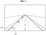
- FIG. 3 illustrates a situation in which an initial position of initial localization information has a position error ⁇ x with respect to an actual position.
- a map lane boundary line 310 corresponding to the initial localization information may be as shown in FIG. 3 .
- An image lane boundary line 320 appearing in image data that is actually captured by an image sensor may be at a different position from the map lane boundary line 310.
- a position estimation apparatus may compensate for such position error as described with reference to FIGS. 12 , 14 , and 15 .
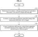
- FIG. 4 is a flowchart illustrating an example of a position estimation method not covered by the claimed invention.
- a position estimation apparatus determines a first rotation reference point based on localization information estimated for a target and map data. Determination of the first rotation reference point will be further described with reference to FIG. 6 .
- the position estimation apparatus estimates a second rotation reference point from image data associated with a front view of the target. Estimation of the second rotation reference point will be further described with reference to FIGS. 7 through 10 .
- the position estimation apparatus corrects the localization information using a rotation parameter calculated based on the first rotation reference point and the second rotation reference point. Correction of the localization information using the rotation parameter will be further described with reference to FIG. 12 .
- FIG. 5 is a diagram illustrating an example of calculating a parameter.
- a second rotation reference point 540 matches a point to which a first rotation reference point 510 corrected based on a predetermined location error and a predetermined rotation error is projected on an image plane.
- a rotation parameter for matching the point to which the first rotation reference point 510 is projected on the image plane and the second rotation reference point 540 is calculated.
- the position estimation apparatus calculates the rotation parameter based on the first rotation reference point 510 and the second rotation reference point 540.
- the first rotation reference point 510 is determined from map data 501 based on initial localization information. For example, based on the initial localization information, an initial position and an initial pose of a target on the map data 501 is determined. Also, the first rotation reference point 510 corresponds, for example, to a vanishing point of lane boundary lines captured by an image sensor at the initial position and the initial pose of the target. As described above, at least two lane boundary lines may not actually intersect in a 3D space. However, when the land boundary lines are projected onto a 2D image plane, a point at which the projected land boundary lines are predicted to intersect may be determined to be the first rotation reference point 510. Such determination of the first rotation reference point 510 will be further described with reference to FIG. 6 .
- position/pose parameter correction 520 is performed on the first rotation reference point 510.
- a position parameter and a pose parameter are compensated for with respect to the first rotation reference point 510.
- perspective projection 530 is applied to the first rotation reference point 510 for which the position parameter and the pose parameter are applied, 2D coordinates 591 of the first rotation reference point 510 are acquired.
- the 2D coordinates 591 of the first rotation reference point 510 may be the same as 2D coordinates 592 of the second rotation reference point 540 detected from an input image 503.
- Such relationship between the first rotation reference point 510 and the second rotation reference point 540 is represented as shown in the following equations.
- v x ′ v y ′ v z ′ f 0 c x 0 f c y 0 0 1 cos ⁇ z ⁇ sin ⁇ z 0 sin ⁇ z cos ⁇ z 0 0 0 1 1 0 0 0 cos ⁇ x ⁇ sin ⁇ x 0 sin ⁇ x cos ⁇ x cos ⁇ y 0 sin ⁇ y 0 1 0 ⁇ sin ⁇ y 0 cos ⁇ y p x ⁇ t x p y ⁇ t y p z ⁇ t z
- Equation 1 p x , p y , and p z are 3D coordinates, for example, x, y, and z coordinates of the first rotation reference point 510.
- t x , t y , and t z are x, y, and z displacement values of a position parameter (for example, a position error), which correspond to a translation transformation.
- ⁇ x , ⁇ y , and ⁇ z are rotation parameters corresponding to a rotation error based on an x axis, a rotation error based on a y axis, and a rotation error based on a z axis.
- cos ⁇ y 0 ⁇ sin ⁇ y 0 1 0 ⁇ sin ⁇ y 0 cos ⁇ y is a rotation transformation by ⁇ y with respect to the y axis.
- 1 0 0 0 cos ⁇ x ⁇ sin ⁇ y 0 sin ⁇ x cos ⁇ x is a rotation transformation by ⁇ x with respect to the x axis.
- cos ⁇ z ⁇ sin ⁇ z 0 sin ⁇ z cos ⁇ z 0 0 0 1 is a rotation transformation by ⁇ z with respect to the z axis.
- f 0 c x 0 f c y 0 0 1 is a matrix for converting the 3D coordinates of the first rotation reference point 510 to which the rotation transformation and the translation transformation are applied into 2D coordinates through the perspective projection 530.
- f is a focal distance of an image sensor.
- c x , and c y are an x coordinate and a y coordinate of a principal point as camera intrinsic information 502, for example, a camera intrinsic parameter.
- v' x , v' y , and v' z are 3D coordinates, for example, x, y, and z coordinates of the first rotation reference point 510 projected onto the image plane after error correction.
- v' x , v' y , and v' z are the coordinates for convenience of matrix operation
- v' x , v' y , and v' z are points on a homogeneous coordinate system and thus, expressed as 2D coordinates as shown in Equation 2 below.
- v x v x ′ v z ′
- v y v y ′ v z ′
- Equation 3 When Equation 1 is arranged based on 2D plane coordinates, Equation 3 is obtained as shown below.
- v x v y f sin ⁇ x q y + cos ⁇ x cos ⁇ z ⁇ sin ⁇ z sin ⁇ z cos ⁇ z q x cos ⁇ x q y ⁇ sin ⁇ x + c x c y .
- Equation 3 q x and q y are expressed as shown in Equation 4 below.
- ⁇ q x cos ⁇ y p x ⁇ t x + sin ⁇ y p z ⁇ t z ⁇ sin ⁇ y p x ⁇ t x + cos ⁇ y p z ⁇ t z
- q y p y ⁇ t y ⁇ sin ⁇ y p x ⁇ t x + cos ⁇ y p z ⁇ t z
- Equation 4 according to characteristics of a vanishing point, p z is sufficiently large relative to p y (for example, p z >> p y ), so p y /p z may converge to 0.
- p x /p z is also referred to as ⁇ x , ⁇ x being a constant.
- t x , t y , and t z of unknowns t x , t y , t z , ⁇ x , ⁇ y , and ⁇ z are removed.
- q x and q y are expressed as shown in Equation 5 below.
- Equation 7 two simultaneous equations are established for x-axial rotation and y-axial rotation as shown in Equation 7 below.
- Equations 6 and 7 are derived under an assumption that the 2D coordinates 591 of the first rotation reference point 510 are the same as the 2D coordinates 592 the second rotation reference point 540.
- the position estimation apparatus determines a rotation parameter for compensating for the first rotation reference point 510 such that the point to which the first rotation reference point 510 is projected on the image plane matches the second rotation reference point 540.
- the position estimation apparatus calculates a rotation parameter satisfying Equation 6 or 7 based on the 3D coordinates of the first rotation reference point 510, the 2D coordinates 592 of the second rotation reference point 540, the camera intrinsic parameter, and a roll angle, for example, ⁇ z of the target.
- FIG. 6 is a diagram illustrating an example of a first rotation reference point.
- a position estimation apparatus determines, to be a first rotation reference point 650, a point sufficiently distanced from a target 610 among points on a lane boundary line.
- the first rotation reference point 650 corresponds to a vanishing point at which lane boundary lines 631 intersect on an image plane. This is because a point converts to a vanishing point on an image plane as a distance from the target 610 to the point is sufficiently long.
- the position estimation apparatus extracts a candidate area 620 based on location information from map data.
- the position estimation apparatus loads map data associated with a current position of the target 610 from a map database 601. For example, the position estimation apparatus extracts an area adjacent to the target 610 in front of the target 610 as the candidate area 620.
- the position estimation apparatus extracts an area including the lane boundary line 631 associated with a lane 632 in which the target 610 is travelling as the candidate area 620. This is because, among the lane boundary lines 631 defining the lane 632 in which the target 610 including the position estimation apparatus is travelling, a lane boundary line close to the target 610 is likely to be stably captured by an image sensor.
- the position estimation apparatus determines the first rotation reference point 650 based on the candidate area 620.
- the position estimation apparatus spans the lane boundary line 631 included in the candidate area 620. For example, the position estimation apparatus selects at least two waypoints from waypoints defining the lane boundary line 631 included in the candidate area 620 and spans a straight line connecting the selected waypoints.
- span of the lane boundary line 631 is not limited to the example.
- the position estimation apparatus may calculate an average gradient of the waypoints defining the lane boundary line 631 and span a straight line having the calculated gradient.
- the position estimation apparatus determines, to be the first rotation reference point 650, a point located beyond a threshold distance 641 from the target 610 among points on a spanned lane boundary line 640.
- 3D coordinates of the determined first rotation reference point 650 are expressed as (p x , p y , p z ).
- FIG. 6 illustrates a 2D top view for ease of description, a 3D coordinate system of map data may be converted into a 3D coordinate system having the target 610 (for example, a predetermined point on a perimeter of the target 610 as an origin. Accordingly, the first rotation reference point 650 may be represented by a coordinate system based on the target 610.
- a second rotation reference point used as a reference for comparison with the first rotation reference point 650 will be described with reference to FIG. 7 below.
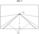
- FIG. 7 is a diagram illustrating an example of a second rotation reference point.
- a position estimation apparatus detects a second rotation reference point 720 from image data.
- the position estimation apparatus detects the second rotation reference point 720 from the image data based on a vanishing-point detection model.
- the position estimation apparatus detects an intersection point of lane boundary lines 710 as the second rotation reference point 720.
- the vanishing-point detection model may be obtained by mathematically modeling geometrical and structural information, for example, a gradient, of boundary lines.
- the position estimation apparatus detects the second rotation reference point 720 from the detected lane boundary lines based on a mathematical model.
- detection of the second rotation reference point 720 is not limited to the example and a machine learning structure may also be used as the vanishing-point detection model. Detection of the second rotation reference point 720 using a machine learning structure will be further described with reference to FIGS. 8 through 10 .
- FIGS. 8 through 10 are diagrams illustrating examples of a vanishing-point detection model for detecting a second rotation reference point.
- a position estimation apparatus detects a second rotation reference point from image data based on vanishing-point detection models 810, 910, and 1010.
- a vanishing-point detection model may be implemented using a machine learning structure and include, for example, a neural network.
- a neural network is, for example, a deep neural network (DNN).
- the DNN may include a fully connected network, a deep convolutional neural network (CNN), a recurrent neural network (RNN), a deep belief network, a bi-directional neural network, or a restricted Boltzman machine, or may include different or overlapping neural network portions respectively with full, convolutional, recurrent, and/or bi-directional connections.
- the neural network performs, for example, object classification, object recognition, voice recognition, and image recognition by mutually mapping input data and output data in a nonlinear relationship based on deep learning.
- the deep learning is a machine learning scheme for solving issues related to, for example, image or speed recognition from a big data set. The input data and the output data are mapped through supervised or unsupervised learning of the deep learning.
- the neural network includes an input layer, a hidden layer, and an output layer.
- the input layer, the hidden layer, and the output layer each include a plurality of nodes.
- the hidden layer may include a number of layers in various ways. Input data may be input directly to the input layer and also be input directly to the hidden layer.
- nodes of layers other than the output layer are connected to nodes of a subsequent layer through links for transmitting output signals. A number of the links corresponds to a number of the nodes included in the subsequent layer.
- an output of an activation function associated with weighted inputs of nodes included in a previous layer is input.
- the weighted input is obtained by multiplying inputs of the nodes included in the previous layer by a synaptic weight.
- the synaptic weight is also referred to as a model parameter of the neural network.
- the activation function includes, for example, a sigmoid, a hyperbolic tangent (tanh), and a rectified linear unit (ReLU). The activation function is used to form a nonlinearity of the neural network.
- the weighted inputs of the nodes included in the previous layer are input to each of nodes included in the output layer.
- the neural network calculates function values corresponding to a number of classes to be classified and recognized in the output layer through the hidden layer, and classifies the input data as a class having a greatest value thereof.
- the neural network may have a capacity of implementing a predetermined function.
- the neural network learns a sufficient amount of training data through an appropriate training process, an optimal recognition performance may be achieved.
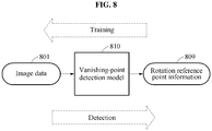
- FIG. 8 illustrates a basic structure of a vanishing-point detection model 810.
- the vanishing-point detection model 810 may be implemented in a machine learning structure trained to output rotation reference point information 809 from image data 801.
- the vanishing-point detection model 810 may include, but is not limited to, the aforementioned neural network.
- the rotation reference point information 809 may be 2D coordinates, for example, an x coordinate and a y coordinate, on an image plane of a point corresponding to a second rotation reference point.
- dimensions of an input layer and an output layer are fixed, but a structure of a hidden layer may be unlimited.
- a training apparatus trains the vanishing-point detection model 810 based on training data.
- the training data includes a pair of a training input and a training output.
- the training output may be ground truth data given for a predetermined training input and may be a training reference point, for example, coordinates of a rotation reference point.
- the training apparatus trains the vanishing-point detection model 810 to output the training reference point from a training image.
- the training apparatus updates a model parameter such that a loss between the training reference value and a temporary output calculated based on the vanishing-point detection model 810 from the training image.
- the training apparatus repetitively updates a model parameter until the loss converges.
- the trained model is stored in a position estimation apparatus.
- FIG. 9 illustrates an operation using a lane boundary detection model 920 and a vanishing-point detection model 910.
- the position estimation apparatus extracts a landmark object from image data 901. For example, the position estimation apparatus detects, based on the vanishing-point detection model 910, a second rotation reference point as rotation reference point information 909 from the landmark object.
- the position estimation apparatus detects a lane boundary as the landmark object.
- the position estimation apparatus detects, based on the lane boundary detection model 920, the lane boundary from the image data 901.
- the lane boundary detection model 920 may be a model trained to output points corresponding to the land boundary from the image data 901.
- a training apparatus loads the lane boundary detection model 920 trained in advance.
- the training apparatus outputs, based on the trained lane boundary detection model 920, a lane boundary image from the image data 901.
- the training apparatus calculates, based on the vanishing-point detection model 910, a temporary output from the land boundary image and updates a model parameter based on a loss between the temporary output and a training output.
- the training apparatus may update only a model parameter of the vanishing-point detection model 910 while maintaining a model parameter of the lane boundary detection model 920.
- joint training may be performed on both of the vanishing-point detection model 910 and the lane boundary detection model 920 as described with reference to FIG. 10 .
- FIG. 10 illustrates an example of training a same neural network structure as that of the example of FIG. 9 .
- a position estimation apparatus outputs, based on a lane boundary detection model 1020, lane boundary information 1008 from image data 1001.
- the position estimation apparatus outputs, based on a vanishing-point detection model 1010, rotation reference point information 1009 from the lane boundary information 1008.
- a training apparatus calculates the lane boundary information 1008 by propagating the image data 1001 to the lane boundary detection model 1020. Also, the training apparatus calculates the rotation reference point information 1009 by propagating the lane boundary information 1008 to the vanishing-point detection model 1010. The training apparatus updates model parameters of the lane boundary detection model 1020 and the vanishing-point detection model 1010 simultaneously or sequentially, based on a reference point loss of the rotation reference point information 1009 and a lane boundary loss of the lane boundary information 1008. In such training process, training of the vanishing-point detection model 1010 and training of the lane boundary detection model 1020 may improve each other.
- FIG. 11 is a diagram illustrating an example of a rotation reference point between initial localization information estimated for a position estimation apparatus and a real pose of the position estimation apparatus.
- a position estimation apparatus determines a point located beyond a threshold distance from the target 1110 among points defining a boundary line of a lane in which the target 1110 is travelling, to be a first rotation reference point 1150.
- a point 1151 to which the first rotation reference point 1150 is projected is indicated as shown in FIG. 11 .
- a real target 1120 is oriented parallel to the lane boundary.
- a sensor 1121 of the real target 1120 captures a front-view image from the target 1120.
- the position estimation apparatus detects a second rotation reference point 1161 from image data 1160 as described with reference to FIGS. 7 through 10 .
- a point to which the first rotation reference point 1150 is projected directly on the image plane and the second rotation reference point 1161 may appear at different points.
- a difference 1156 between the point to which the first rotation reference point 1150 is projected on the image plane and the second rotation reference point 1161 may correspond to the error, for example, a rotation error and a position error, in the initial localization information.
- the position estimation apparatus may correct the initial localization information as described with reference to FIG. 12 below.
- FIG. 12 is a diagram illustrating an example of an operation of correcting initial localization information using first rotation reference point and second rotation reference point.
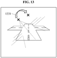
- FIG. 13 is a diagram illustrating an example of an operation of correcting localization information using a rotation parameter.
- FIGS. 14 and 15 are diagrams illustrating examples of an operation of correcting localization information using a position parameter.
- a position estimation apparatus acquires map data 1201.
- the position estimation apparatus determines a first rotation reference point based on initial localization information from the map data 1201.
- the description of determining the first rotation reference point is made with reference to FIG. 6 and thus, a repeated description of determining the first rotation reference point will be omitted.
- the position estimation apparatus acquires image data 1202.
- the position estimation apparatus detects a second rotation reference point from the image data 1202 based on a vanishing-point detection model 1203.
- the vanishing-point detection model 1203 may be a mathematical model or a model of a machine learning structure.
- the position estimation apparatus corrects the initial localization information using a rotation parameter and a position parameter. A detailed description of operation 1230 is provided below.
- the position estimation apparatus calculates a rotation parameter and corrects the initial localization information using the rotation parameter.
- the position estimation apparatus calculates the rotation parameter based on the first rotation reference point and the second rotation reference point. For example, the position estimation apparatus calculates a rotation parameter associated with an initial pose from the first rotation reference point and the second rotation reference point.
- the position estimation apparatus determines final localization information by correcting localization information based on the calculated rotation parameter. For example, the position estimation apparatus determines a final pose of a target by correcting the initial pose using the rotation parameter.
- the position estimation apparatus calculates a position parameter associated with the initial position of the target after determining the final pose as described above.
- the position estimation apparatus determines a final position of the target by correcting the initial position using the position parameter.
- the position estimation apparatus calculates a first axis position parameter and corrects the localization information using the first axis position parameter.
- the position estimation apparatus applies an offset on a first axis to the initial position.
- the position estimation apparatus applies a component corresponding to a lateral axis from the position parameter to the localization information.
- a position on the first axis to which the first rotation reference point is projected on the image plane may be moved.
- the position estimation apparatus calculates a second axis position parameter and corrects the localization information using the second axis position parameter.
- the position estimation apparatus applies an offset on a second axis, which is different from the first axis, to the initial position.
- the position estimation apparatus applies a component corresponding to a longitudinal axis from the position parameter to the localization information.
- the position estimation apparatus determines a position parameter, for example, the first axis position parameter and the second axis position parameter, based on an image landmark detected from the image data 1202 and a map landmark detected from the map data 1201. For example, the position estimation apparatus calculates the position parameter based on a difference between 2D coordinates of the map landmark detected from the map data 1201 and 2D coordinates of the image landmark corresponding to the map landmark. The position estimation apparatus sets a landmark score for each landmark detected from the image data 1202.
- the position estimation apparatus projects the map landmark included in the map data 1201 to an image plane (for example, a plane based on an angle of field of a sensor at an initial position and an initial pose) and calculates a matching score based on a degree of overlap between image landmarks in the image data 1202.
- the position estimation apparatus determines a position parameter corresponding to a coordinate movement value indicating a highest matching score.
- the position estimation apparatus calculates the position parameter and the rotation parameter and applies the position parameter and the rotation parameter to the initial localization information, thereby determining accurate final localization information.
- the position estimation apparatus Based on the final localization information, the position estimation apparatus provides information used for determining whether the target reaches a predetermined place on the map data 1201 or whether the target is deviated from a path.
- the position estimation apparatus may be combined with a vehicle information system.
- a position estimation method may be implemented in a form of software, web service, and a chip in a vehicular device so as to be provided.
- the position estimation apparatus may be applied to localization based on the image and the map data 1201 in an AR environment.
- the position estimation apparatus may be provided at low cost and in a small size.
- the position estimation apparatus compensates for the error using the position parameter and the rotation parameter as described above.
- the position estimation apparatus may determine the position parameter and the rotation parameter without restrictions on the number of landmarks, for example, even when the number of landmarks is less than 4.
- the position estimation apparatus may robustly determine a rotation parameter for compensating for a rotation error, which is a critical factor of localization, using rotation reference points.
- the processor 120 and the memory 130 in FIG. 1 that perform the operations described in this application are implemented by hardware components configured to perform the operations described in this application that are performed by the hardware components.
- hardware components that may be used to perform the operations described in this application where appropriate include controllers, sensors, generators, drivers, memories, comparators, arithmetic logic units, adders, subtractors, multipliers, dividers, integrators, and any other electronic components configured to perform the operations described in this application.
- one or more of the hardware components that perform the operations described in this application are implemented by computing hardware, for example, by one or more processors or computers.
- a processor or computer may be implemented by one or more processing elements, such as an array of logic gates, a controller and an arithmetic logic unit, a digital signal processor, a microcomputer, a programmable logic controller, a field-programmable gate array, a programmable logic array, a microprocessor, or any other device or combination of devices that is configured to respond to and execute instructions in a defined manner to achieve a desired result.
- a processor or computer includes, or is connected to, one or more memories storing instructions or software that are executed by the processor or computer.
- Hardware components implemented by a processor or computer may execute instructions or software, such as an operating system (OS) and one or more software applications that run on the OS, to perform the operations described in this application.
- OS operating system
- the hardware components may also access, manipulate, process, create, and store data in response to execution of the instructions or software.
- processor or “computer” may be used in the description of the examples described in this application, but in other examples multiple processors or computers may be used, or a processor or computer may include multiple processing elements, or multiple types of processing elements, or both.
- a single hardware component or two or more hardware components may be implemented by a single processor, or two or more processors, or a processor and a controller.
- One or more hardware components may be implemented by one or more processors, or a processor and a controller, and one or more other hardware components may be implemented by one or more other processors, or another processor and another controller.
- One or more processors may implement a single hardware component, or two or more hardware components.
- a hardware component may have any one or more of different processing configurations, examples of which include a single processor, independent processors, parallel processors, single-instruction single-data (SISD) multiprocessing, single-instruction multiple-data (SIMD) multiprocessing, multiple-instruction single-data (MISD) multiprocessing, and multiple-instruction multiple-data (MIMD) multiprocessing.
- SISD single-instruction single-data
- SIMD single-instruction multiple-data
- MIMD multiple-instruction multiple-data
- FIGS. 4 , 5 , 8-10 , and 12 that perform the operations described in this application are performed by computing hardware, for example, by one or more processors or computers, implemented as described above executing instructions or software to perform the operations described in this application that are performed by the methods.
- a single operation or two or more operations may be performed by a single processor, or two or more processors, or a processor and a controller.
- One or more operations may be performed by one or more processors, or a processor and a controller, and one or more other operations may be performed by one or more other processors, or another processor and another controller.
- One or more processors, or a processor and a controller may perform a single operation, or two or more operations.
- Instructions or software to control a processor or computer to implement the hardware components and perform the methods as described above are written as computer programs, code segments, instructions or any combination thereof, for individually or collectively instructing or configuring the processor or computer to operate as a machine or special-purpose computer to perform the operations performed by the hardware components and the methods as described above.
- the instructions or software include machine code that is directly executed by the processor or computer, such as machine code produced by a compiler.
- the instructions or software include higher-level code that is executed by the processor or computer using an interpreter. Programmers of ordinary skill in the art can readily write the instructions or software based on the block diagrams and the flow charts illustrated in the drawings and the corresponding descriptions in the specification, which disclose algorithms for performing the operations performed by the hardware components and the methods as described above.
- Non-transitory computer-readable storage medium examples include read-only memory (ROM), random-access programmable read only memory (PROM), electrically erasable programmable read-only memory (EEPROM), random-access memory (RAM), dynamic random access memory (DRAM), static random access memory (SRAM), flash memory, non-volatile memory, CD-ROMs, CD-Rs, CD+Rs, CD-RWs, CD+RWs, DVD-ROMs, DVD-Rs, DVD+Rs, DVD-RWs, DVD+RWs, DVD-RAMs, BD-ROMs, BD-Rs, BD-R LTHs, BD-REs, blue-ray or optical disk storage, hard disk drive (HDD), solid state drive (SSD), flash memory,
- HDD hard disk drive
- SSD solid state drive
Landscapes
- Engineering & Computer Science (AREA)
- Radar, Positioning & Navigation (AREA)
- Remote Sensing (AREA)
- Physics & Mathematics (AREA)
- General Physics & Mathematics (AREA)
- Automation & Control Theory (AREA)
- Computer Networks & Wireless Communication (AREA)
- Multimedia (AREA)
- Theoretical Computer Science (AREA)
- Image Analysis (AREA)
- Navigation (AREA)
- Position Fixing By Use Of Radio Waves (AREA)
- Image Processing (AREA)
Description
- The following description relates to technology for estimating a position.
- When an object equipped with a global positioning system (GPS) navigation system, such as a vehicle or the like, is moving, the navigation system may receive radio waves from a satellite belonging to a plurality of GPSs, and verifies a current position of the moving object and a speed of the moving object. The navigation system may calculate a three-dimensional (3D) current position of the moving object including latitude, longitude, and altitude information using information received from a GPS receiver. However, GPS signals may include a GPS position error of about 10 meters (m) to 100 m. Such position error may be corrected using other information.
- Reference is made here to GUI DIXIAO ET AL: "Real-Time Global Localization of Robotic Cars in Lane Level via Lane Marking Detection and Shape Registration", IEEE TRANSACTIONS ON INTELLIGENT TRANSPORTATION SYSTEMS, IEEE, PISCATAWAY, NJ, USA, vol. 17, no. 4, 1 April 2016 (2016-04-01), pages 1039-1050, XP011604459, which is acknowledged here to constitute the closest prior art. The present invention may be distinguished therefrom at least by features in characterising portions of the appended independent claims.
- Documents
EP 3 333 803 A1 andUS 2010/09745 are acknowledged here to constitute further prior art. - This Summary is provided to introduce a selection of concepts in a simplified form that are further described below in the Detailed Description.
- In one general aspect, a method of estimating a position includes the steps specified in the appended independent method claim.
- Preferred embodiments of the method in accordance with the present invention are subject of the appended dependent method claims.
- In another general aspect, a non-transitory computer-readable storage medium stores instructions that, when executed by a processor, cause the processor to perform the method of estimating a position described above.
- An apparatus for estimating a position exhibits the features specified in the appended independent apparatus claim.
- Preferred embodiments of an apparatus in accordance with the present invention are subject of the appended dependent apparatus claims.
- Other features and aspects will be apparent from the following detailed description and the drawings.
-
-
FIG. 1 illustrates an example of a position estimation apparatus. -
FIGS. 2 and3 illustrate examples of a position estimation error. -
FIG. 4 illustrates an example of a position estimation method not covered by the claimed invention. -
FIG. 5 illustrates an example of calculating a parameter. -
FIG. 6 illustrates an example of a first rotation reference point. -
FIG. 7 illustrates an example of a second rotation reference point. -
FIGS. 8 through 10 illustrate examples of a vanishing-point detection model for detecting a second rotation reference point. -
FIG. 11 illustrates an example of a rotation reference point error between initial localization information estimated for a position estimation apparatus and a real pose of the position estimation apparatus. -
FIG. 12 illustrates an example of an operation of correcting initial localization information using a first rotation reference point and a second rotation reference point. -
FIG. 13 illustrates an example of an operation of correcting localization information using a rotation parameter. -
FIGS. 14 and15 illustrate examples of an operation of correcting localization information using a position parameter. - Throughout the drawings and the detailed description, unless otherwise described or provided, the same drawing reference numerals will be understood to refer to the same elements, features, and structures. The drawings may not be to scale, and the relative size, proportions, and depiction of elements in the drawings may be exaggerated for clarity, illustration, and convenience.
- The following detailed description is provided to assist the reader in gaining a comprehensive understanding of the methods, apparatuses, and/or systems described herein. For example, the sequences of operations described herein are merely examples, and are not limited to those set forth herein, but may be changed as will be apparent after an understanding of the disclosure of this application, with the exception of operations necessarily occurring in a certain order. Also, descriptions of features that are known in the art may be omitted for increased clarity and conciseness.
- The features described herein may be embodied in different forms within the scope of the appended claims, and are not to be construed as being limited to the examples described herein.
- Herein, it is noted that use of the term "may" with respect to an example or embodiment, e.g., as to what an example or embodiment may include or implement, means that at least one example or embodiment exists in which such a feature is included or implemented while all examples and embodiments are not limited thereto.
- Throughout the specification, when an element, such as a layer, region, or substrate, is described as being "on," "connected to," or "coupled to" another element, it may be directly "on," "connected to," or "coupled to" the other element, or there may be one or more other elements intervening therebetween. In contrast, when an element is described as being "directly on," "directly connected to," or "directly coupled to" another element, there can be no other elements intervening therebetween.
- As used herein, the term "and/or" includes any one and any combination of any two or more of the associated listed items.
- Although terms such as "first," "second," and "third" may be used herein to describe various members, components, regions, layers, or sections, these members, components, regions, layers, or sections are not to be limited by these terms. Rather, these terms are only used to distinguish one member, component, region, layer, or section from another member, component, region, layer, or section. Thus, a first member, component, region, layer, or section referred to in examples described herein may also be referred to as a second member, component, region, layer, or section without departing from the teachings of the examples.
- The terminology used herein is for describing various examples only, and is not to be used to limit the disclosure. The articles "a," "an," and "the" are intended to include the plural forms as well, unless the context clearly indicates otherwise. The terms "comprises," "includes," and "has" specify the presence of stated features, numbers, operations, members, elements, and/or combinations thereof, but do not preclude the presence or addition of one or more other features, numbers, operations, members, elements, and/or combinations thereof.
- Unless otherwise defined, all terms, including technical and scientific terms, used herein have the same meaning as commonly understood by one of ordinary skill in the art to which this disclosure pertains. Terms, such as those defined in commonly used dictionaries, are to be interpreted as having a meaning that is consistent with their meaning in the context of the relevant art, and are not to be interpreted in an idealized or overly formal sense unless expressly so defined herein.
- The features of the examples described herein may be combined in various ways as will be apparent after an understanding of the disclosure of this application. Further, although the examples described herein have a variety of configurations, other configurations are possible within the scope of the appended claims.
-
FIG. 1 is a block diagram illustrating an example of aposition estimation apparatus 100. In the description herein related to theposition estimation apparatus 100, the term "target" refers to an object of which a pose and position are estimated by theposition estimation apparatus 100. For example, theposition estimation apparatus 100 may be mounted on a vehicle. In this example, the target may be the vehicle. - Referring to
FIG. 1 , theposition estimation apparatus 100 includes, for example, asensor 110, aprocessor 120, and amemory 130. - The
sensor 110 generates sensing data. For example, thesensor 110 generates sensing data by sensing information used for estimating a position. The information used for estimating a position includes various signals, for example, global positioning system (GPS) signals, an acceleration signal, a velocity signal, and an image signal. Theprocessor 120 primarily measures initial localization information using the sensing data. The initial localization information includes information indicating a position and a pose of the target measured coarsely. For example, thesensor 110 includes inertial measurement unit (IMU) and GPS modules. Thesensor 110 acquires an IMU signal and GPS signals indicating an acceleration and an angular velocity of the target as the sensing data. - The IMU is also referred to as "inertial measurer". The IMU measures a change in pose, a change speed for position movement, and a displacement. The IMU includes a three-axis accelerometer that senses a translational motion, for example, an acceleration and a three-axis gyroscope that senses a rotation motion, for example, an angular velocity. Since the IMU does not depend on external information, an acceleration signal and an angular velocity signal may be stably collected. A GPS module receives signals transmitted from at least three artificial satellites to calculate positions of the satellites and the
position estimation apparatus 100, and may also be referred to as a global navigation satellite system (GNSS). The GPS module measures an absolute position at 1 hertz and has relatively low noise. Thus, the GPS module may operate stably. An IMU 301 measures a relative position at 100 Hz and performs measurement at high speed. - Also, the
sensor 110 senses image data. For example, thesensor 110 includes a camera sensor. The camera sensor receives light in a visible light range and senses an intensity of the light. The camera sensor generates a color image by sensing an intensity of light corresponding to each of a red channel, a blue channel, and a green channel. However, a type of thesensor 110 is not limited to the described example. Thesensor 110 may include, for example, an infrared sensor, a Lidar sensor, a RADAR sensor, a thermal image sensor, and/or a depth sensor. The camera sensor captures an external view, for example, a front view from theposition estimation apparatus 100 to generate image data. - The
processor 120 determines a first rotation reference point based on map data and localization information estimated for the target. The localization information includes information on a position, a pose, and a movement, for example, a speed and an acceleration of the target. - In this disclosure, the term "rotation reference point" refers to a point used as a reference for correcting a rotation error in the localization information estimated for the target. The first rotation reference point is a rotation reference point determined based on the map data. For example, the first rotation reference point may be a three-dimensional (3D) point corresponding to a vanishing point on a two-dimensional (2D) image plane and may indicate a point sufficiently distanced from an image sensor among points on a lane boundary line. Determination of the first rotation reference point will be further described with reference to
FIG. 6 . - The
processor 120 estimates a second rotation reference point from image data associated with a front view of the target. The second rotation reference point is a rotation reference point estimated using image data sensed by thesensor 110. For example, at least two straight lines parallel to each other may be projected onto a 2D image plane. In this example, the second rotation reference point is, as a kind of a vanishing point, a point to which the straight lines converge. Determination of the second rotation point will be further described with reference toFIGS. 7 through 10 . - The
processor 120 corrects localization information using a rotation parameter calculated based on the first rotation reference point and the second rotation reference point. The rotation parameter is a parameter for compensating for an error between primarily estimated initial localization information and actual position and pose of the target. For example, the camera sensor included in thesensor 110 may be attached to the target, for example, the vehicle, to have an optical axis parallel to a longitudinal axis of the target. In this example, since the camera sensor makes a same motion as a motion of the target, the image data sensed by the camera sensor includes visual information matching the position and pose of the target. Thus, theprocessor 120 may apply the rotation parameter such that the first rotation reference point corresponding to the initial localization information matches the second rotation reference point detected from the image data. Calculation of the rotation parameter will be further described with reference toFIG. 5 . An application of the rotation will be further described with reference toFIGS. 11 through 15 . - The
memory 130 temporarily or permanently stores data required to perform a position estimation method. For example, thememory 130 stores a vanishing-point detection model for detecting a rotation reference point from image data and a model parameter of the vanishing-point detection model. The vanishing-point detection model will be described with reference toFIGS. 9 and10 . - As described above, the
position estimation apparatus 100 estimates initial localization information including an initial position and an initial pose of the target based on sensing data sensed by thesensor 110. The initial localization information may include a pose error and a position error. An error in the initial localization information will be described with reference toFIGS. 2 and3 . -
FIGS. 2 and3 are diagrams illustrating examples of a position estimation error. - A position estimation apparatus measures initial localization information using GPS signals and an acceleration signal.
FIG. 2 illustrates a situation in which an initial pose of the initial localization information has a rotation error Δθ with respect to an actual pose. The initial localization information indicates that a target including the position estimation apparatus has a predetermined initial position and a predetermined initial pose. According to map data, for example, a high definition (HD) map, a maplane boundary line 210 corresponding to the initial localization information may be as shown inFIG. 2 . An imagelane boundary line 220 appearing in image data that is actually captured by an image sensor may be at an angle different from that of the maplane boundary line 210. The position estimation apparatus compensates for such rotation error using a rotation parameter calculated as described with reference toFIG. 5 . - The map data includes information associated with a map and includes, for example, information on a landmark. The landmark is an object fixed at a predetermined geographical position to provide a driver with information required to drive a vehicle on a road. For example, road signs and traffic lights may belong to the landmark. For example, according to the Korean Road Traffic act, landmarks are classified into six classes, for example, a caution sign, a regulatory sign, an indication sign, an auxiliary sign, a road sign, and a signal sign. However, classification of the landmarks is not limited to the foregoing. Classes of the landmark may differ for each country.
- Also, in this disclosure, the term "lane boundary line" refers to a line defining a lane. The land boundary line is, for example, a solid line or a broken line marked on a road surface, or a curb arranged along an outer edge of a road.
-
FIG. 3 illustrates a situation in which an initial position of initial localization information has a position error Δx with respect to an actual position. According to map data, a maplane boundary line 310 corresponding to the initial localization information may be as shown inFIG. 3 . An imagelane boundary line 320 appearing in image data that is actually captured by an image sensor may be at a different position from the maplane boundary line 310. A position estimation apparatus may compensate for such position error as described with reference toFIGS. 12 ,14 , and15 . -
FIG. 4 is a flowchart illustrating an example of a position estimation method not covered by the claimed invention. - In
operation 410, a position estimation apparatus determines a first rotation reference point based on localization information estimated for a target and map data. Determination of the first rotation reference point will be further described with reference toFIG. 6 . - In
operation 420, the position estimation apparatus estimates a second rotation reference point from image data associated with a front view of the target. Estimation of the second rotation reference point will be further described with reference toFIGS. 7 through 10 . - In
operation 430, the position estimation apparatus corrects the localization information using a rotation parameter calculated based on the first rotation reference point and the second rotation reference point. Correction of the localization information using the rotation parameter will be further described with reference toFIG. 12 . -
FIG. 5 is a diagram illustrating an example of calculating a parameter. - In the example of
FIG. 5 , it is assumed that a secondrotation reference point 540 matches a point to which a firstrotation reference point 510 corrected based on a predetermined location error and a predetermined rotation error is projected on an image plane. By arranging an equation under this assumption, a rotation parameter for matching the point to which the firstrotation reference point 510 is projected on the image plane and the secondrotation reference point 540 is calculated. The position estimation apparatus calculates the rotation parameter based on the firstrotation reference point 510 and the secondrotation reference point 540. Hereinafter, a process of deriving an equation for calculating the rotation parameter will be described. - The first
rotation reference point 510 is determined frommap data 501 based on initial localization information. For example, based on the initial localization information, an initial position and an initial pose of a target on themap data 501 is determined. Also, the firstrotation reference point 510 corresponds, for example, to a vanishing point of lane boundary lines captured by an image sensor at the initial position and the initial pose of the target. As described above, at least two lane boundary lines may not actually intersect in a 3D space. However, when the land boundary lines are projected onto a 2D image plane, a point at which the projected land boundary lines are predicted to intersect may be determined to be the firstrotation reference point 510. Such determination of the firstrotation reference point 510 will be further described with reference toFIG. 6 . - When the initial localization information, for example, the initial position and the initial pose, has the aforementioned position error and pose error, position/pose
parameter correction 520 is performed on the firstrotation reference point 510. For example, a position parameter and a pose parameter are compensated for with respect to the firstrotation reference point 510. Whenperspective projection 530 is applied to the firstrotation reference point 510 for which the position parameter and the pose parameter are applied, 2D coordinates 591 of the firstrotation reference point 510 are acquired. Here, the 2D coordinates 591 of the firstrotation reference point 510 may be the same as 2D coordinates 592 of the secondrotation reference point 540 detected from aninput image 503. Such relationship between the firstrotation reference point 510 and the secondrotation reference point 540 is represented as shown in the following equations.
- In
Equation 1, px, py, and pz are 3D coordinates, for example, x, y, and z coordinates of the firstrotation reference point 510. tx, ty, and tz are x, y, and z displacement values of a position parameter (for example, a position error), which correspond to a translation transformation. θ x, θy , and θz are rotation parameters corresponding to a rotation error based on an x axis, a rotation error based on a y axis, and a rotation error based on a z axis.


rotation reference point 510 to which the rotation transformation and the translation transformation are applied into 2D coordinates through theperspective projection 530. f is a focal distance of an image sensor. cx, and cy are an x coordinate and a y coordinate of a principal point as cameraintrinsic information 502, for example, a camera intrinsic parameter. v'x, v'y, and v'z are 3D coordinates, for example, x, y, and z coordinates of the firstrotation reference point 510 projected onto the image plane after error correction. - Although v'x, v'y, and v'z are the coordinates for convenience of matrix operation, v'x, v'y, and v'z are points on a homogeneous coordinate system and thus, expressed as 2D coordinates as shown in Equation 2 below.

- When
Equation 1 is arranged based on 2D plane coordinates, Equation 3 is obtained as shown below.
- In Equation 3, qx and qy are expressed as shown in Equation 4 below.

- In Equation 4, according to characteristics of a vanishing point, pz is sufficiently large relative to py (for example, pz >> py), so py/pz may converge to 0. px/pz is also referred to as δx , δx being a constant. Also, according to the characteristics of a vanishing point, tx, ty, and tz of unknowns tx, ty, tz, θx , θy , and θz are removed. In this example, qx and qy are expressed as shown in Equation 5 below.

- Accordingly, qy is removed and qx is expressed as a value for θy among rotation parameters. In this example, when Equation 3 is rearranged, Equation 6 is obtained as shown below.
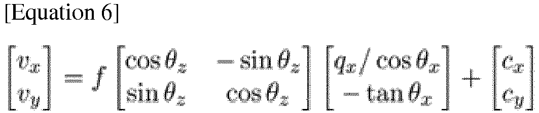
- In Equation 6, when a roll angle of a vehicle is given, (for example, θz =0), Equation 6 is arranged to be an equation for θx and θy . Since variables in Equation 6 other than the unknown θx and θy are given, two simultaneous equations are established for x-axial rotation and y-axial rotation as shown in Equation 7 below.

- Equations 6 and 7 are derived under an assumption that the 2D coordinates 591 of the first
rotation reference point 510 are the same as the 2D coordinates 592 the secondrotation reference point 540. Thus, based on Equations 6 and 7, the position estimation apparatus determines a rotation parameter for compensating for the firstrotation reference point 510 such that the point to which the firstrotation reference point 510 is projected on the image plane matches the secondrotation reference point 540. For example, the position estimation apparatus calculates a rotation parameter satisfying Equation 6 or 7 based on the 3D coordinates of the firstrotation reference point 510, the 2D coordinates 592 of the secondrotation reference point 540, the camera intrinsic parameter, and a roll angle, for example, θz of the target. - An operation of determining 3D coordinates of a first rotation reference point will be described with reference to
FIG. 6 . -
FIG. 6 is a diagram illustrating an example of a first rotation reference point. - A position estimation apparatus determines, to be a first
rotation reference point 650, a point sufficiently distanced from atarget 610 among points on a lane boundary line. As described above, the firstrotation reference point 650 corresponds to a vanishing point at whichlane boundary lines 631 intersect on an image plane. This is because a point converts to a vanishing point on an image plane as a distance from thetarget 610 to the point is sufficiently long. - The position estimation apparatus extracts a
candidate area 620 based on location information from map data. The position estimation apparatus loads map data associated with a current position of thetarget 610 from amap database 601. For example, the position estimation apparatus extracts an area adjacent to thetarget 610 in front of thetarget 610 as thecandidate area 620. The position estimation apparatus extracts an area including thelane boundary line 631 associated with alane 632 in which thetarget 610 is travelling as thecandidate area 620. This is because, among thelane boundary lines 631 defining thelane 632 in which thetarget 610 including the position estimation apparatus is travelling, a lane boundary line close to thetarget 610 is likely to be stably captured by an image sensor. - The position estimation apparatus determines the first
rotation reference point 650 based on thecandidate area 620. The position estimation apparatus spans thelane boundary line 631 included in thecandidate area 620. For example, the position estimation apparatus selects at least two waypoints from waypoints defining thelane boundary line 631 included in thecandidate area 620 and spans a straight line connecting the selected waypoints. However, span of thelane boundary line 631 is not limited to the example. The position estimation apparatus may calculate an average gradient of the waypoints defining thelane boundary line 631 and span a straight line having the calculated gradient. The position estimation apparatus determines, to be the firstrotation reference point 650, a point located beyond athreshold distance 641 from thetarget 610 among points on a spannedlane boundary line 640. 3D coordinates of the determined firstrotation reference point 650 are expressed as (px, py, pz). AlthoughFIG. 6 illustrates a 2D top view for ease of description, a 3D coordinate system of map data may be converted into a 3D coordinate system having the target 610 (for example, a predetermined point on a perimeter of thetarget 610 as an origin. Accordingly, the firstrotation reference point 650 may be represented by a coordinate system based on thetarget 610. - A second rotation reference point used as a reference for comparison with the first
rotation reference point 650 will be described with reference toFIG. 7 below. -
FIG. 7 is a diagram illustrating an example of a second rotation reference point. - A position estimation apparatus detects a second
rotation reference point 720 from image data. The position estimation apparatus detects the secondrotation reference point 720 from the image data based on a vanishing-point detection model. - For example, the position estimation apparatus detects an intersection point of
lane boundary lines 710 as the secondrotation reference point 720. The vanishing-point detection model may be obtained by mathematically modeling geometrical and structural information, for example, a gradient, of boundary lines. The position estimation apparatus detects the secondrotation reference point 720 from the detected lane boundary lines based on a mathematical model. - However, detection of the second
rotation reference point 720 is not limited to the example and a machine learning structure may also be used as the vanishing-point detection model. Detection of the secondrotation reference point 720 using a machine learning structure will be further described with reference toFIGS. 8 through 10 . -
FIGS. 8 through 10 are diagrams illustrating examples of a vanishing-point detection model for detecting a second rotation reference point. - A position estimation apparatus detects a second rotation reference point from image data based on vanishing-
point detection models - A neural network is, for example, a deep neural network (DNN). The DNN may include a fully connected network, a deep convolutional neural network (CNN), a recurrent neural network (RNN), a deep belief network, a bi-directional neural network, or a restricted Boltzman machine, or may include different or overlapping neural network portions respectively with full, convolutional, recurrent, and/or bi-directional connections. The neural network performs, for example, object classification, object recognition, voice recognition, and image recognition by mutually mapping input data and output data in a nonlinear relationship based on deep learning. The deep learning is a machine learning scheme for solving issues related to, for example, image or speed recognition from a big data set. The input data and the output data are mapped through supervised or unsupervised learning of the deep learning.
- The neural network includes an input layer, a hidden layer, and an output layer. The input layer, the hidden layer, and the output layer each include a plurality of nodes.
- The hidden layer may include a number of layers in various ways. Input data may be input directly to the input layer and also be input directly to the hidden layer. In the neural network, nodes of layers other than the output layer are connected to nodes of a subsequent layer through links for transmitting output signals. A number of the links corresponds to a number of the nodes included in the subsequent layer.
- In each node included in the hidden layer, an output of an activation function associated with weighted inputs of nodes included in a previous layer is input. The weighted input is obtained by multiplying inputs of the nodes included in the previous layer by a synaptic weight. The synaptic weight is also referred to as a model parameter of the neural network. The activation function includes, for example, a sigmoid, a hyperbolic tangent (tanh), and a rectified linear unit (ReLU). The activation function is used to form a nonlinearity of the neural network. The weighted inputs of the nodes included in the previous layer are input to each of nodes included in the output layer.
- When input data is given, the neural network calculates function values corresponding to a number of classes to be classified and recognized in the output layer through the hidden layer, and classifies the input data as a class having a greatest value thereof.
- When a width and a depth of the neural network are sufficient, the neural network may have a capacity of implementing a predetermined function. When the neural network learns a sufficient amount of training data through an appropriate training process, an optimal recognition performance may be achieved.
-
FIG. 8 illustrates a basic structure of a vanishing-point detection model 810. - Referring to
FIG. 8 , the vanishing-point detection model 810 may be implemented in a machine learning structure trained to output rotationreference point information 809 fromimage data 801. For example, the vanishing-point detection model 810 may include, but is not limited to, the aforementioned neural network. The rotationreference point information 809 may be 2D coordinates, for example, an x coordinate and a y coordinate, on an image plane of a point corresponding to a second rotation reference point. In the vanishing-point detection model 810, dimensions of an input layer and an output layer are fixed, but a structure of a hidden layer may be unlimited. - A training apparatus trains the vanishing-
point detection model 810 based on training data. The training data includes a pair of a training input and a training output. The training output may be ground truth data given for a predetermined training input and may be a training reference point, for example, coordinates of a rotation reference point. The training apparatus trains the vanishing-point detection model 810 to output the training reference point from a training image. For example, the training apparatus updates a model parameter such that a loss between the training reference value and a temporary output calculated based on the vanishing-point detection model 810 from the training image. The training apparatus repetitively updates a model parameter until the loss converges. The trained model is stored in a position estimation apparatus. -
FIG. 9 illustrates an operation using a laneboundary detection model 920 and a vanishing-point detection model 910. - Referring to
FIG. 9 , the position estimation apparatus extracts a landmark object fromimage data 901. For example, the position estimation apparatus detects, based on the vanishing-point detection model 910, a second rotation reference point as rotationreference point information 909 from the landmark object. - The position estimation apparatus detects a lane boundary as the landmark object. The position estimation apparatus detects, based on the lane
boundary detection model 920, the lane boundary from theimage data 901. The laneboundary detection model 920 may be a model trained to output points corresponding to the land boundary from theimage data 901. - A training apparatus loads the lane
boundary detection model 920 trained in advance. The training apparatus outputs, based on the trained laneboundary detection model 920, a lane boundary image from theimage data 901. The training apparatus calculates, based on the vanishing-point detection model 910, a temporary output from the land boundary image and updates a model parameter based on a loss between the temporary output and a training output. The training apparatus may update only a model parameter of the vanishing-point detection model 910 while maintaining a model parameter of the laneboundary detection model 920. - However, in another example, joint training may be performed on both of the vanishing-
point detection model 910 and the laneboundary detection model 920 as described with reference toFIG. 10 . -
FIG. 10 illustrates an example of training a same neural network structure as that of the example ofFIG. 9 . - Referring to
FIG. 10 , a position estimation apparatus outputs, based on a laneboundary detection model 1020,lane boundary information 1008 fromimage data 1001. The position estimation apparatus outputs, based on a vanishing-point detection model 1010, rotationreference point information 1009 from thelane boundary information 1008. - For example, a training apparatus calculates the
lane boundary information 1008 by propagating theimage data 1001 to the laneboundary detection model 1020. Also, the training apparatus calculates the rotationreference point information 1009 by propagating thelane boundary information 1008 to the vanishing-point detection model 1010. The training apparatus updates model parameters of the laneboundary detection model 1020 and the vanishing-point detection model 1010 simultaneously or sequentially, based on a reference point loss of the rotationreference point information 1009 and a lane boundary loss of thelane boundary information 1008. In such training process, training of the vanishing-point detection model 1010 and training of the laneboundary detection model 1020 may improve each other. -
FIG. 11 is a diagram illustrating an example of a rotation reference point between initial localization information estimated for a position estimation apparatus and a real pose of the position estimation apparatus. - In the example of
FIG. 11 , it is assumed that atarget 1110 of a pose based on initial localization information is positioned obliquely with respect to a lane boundary. Here, the pose of thetarget 1110 is virtually illustrated based on the initial localization information. As described with reference toFIG. 6 , a position estimation apparatus determines a point located beyond a threshold distance from thetarget 1110 among points defining a boundary line of a lane in which thetarget 1110 is travelling, to be a firstrotation reference point 1150. When the firstrotation reference point 1150 is projected onto an image plane corresponding to an angle of field of a sensor 1111 attached to thetarget 1110 in the pose based on the initial localization information, apoint 1151 to which the firstrotation reference point 1150 is projected is indicated as shown inFIG. 11 . - Unlike the initial localization information, a
real target 1120 is oriented parallel to the lane boundary. Asensor 1121 of thereal target 1120 captures a front-view image from thetarget 1120. The position estimation apparatus detects a secondrotation reference point 1161 fromimage data 1160 as described with reference toFIGS. 7 through 10 . - As the foregoing, due to an error in the initial localization information, a point to which the first
rotation reference point 1150 is projected directly on the image plane and the secondrotation reference point 1161 may appear at different points. Thus, adifference 1156 between the point to which the firstrotation reference point 1150 is projected on the image plane and the secondrotation reference point 1161 may correspond to the error, for example, a rotation error and a position error, in the initial localization information. - By using the rotation parameter calculated in the example of
FIG. 5 , the position estimation apparatus may correct the initial localization information as described with reference toFIG. 12 below. -
FIG. 12 is a diagram illustrating an example of an operation of correcting initial localization information using first rotation reference point and second rotation reference point.FIG. 13 is a diagram illustrating an example of an operation of correcting localization information using a rotation parameter.FIGS. 14 and15 are diagrams illustrating examples of an operation of correcting localization information using a position parameter. - A position estimation apparatus acquires
map data 1201. Inoperation 1210, the position estimation apparatus determines a first rotation reference point based on initial localization information from themap data 1201. The description of determining the first rotation reference point is made with reference toFIG. 6 and thus, a repeated description of determining the first rotation reference point will be omitted. - The position estimation apparatus acquires
image data 1202. Inoperation 1220, the position estimation apparatus detects a second rotation reference point from theimage data 1202 based on a vanishing-point detection model 1203. The vanishing-point detection model 1203 may be a mathematical model or a model of a machine learning structure. - In
operation 1230, the position estimation apparatus corrects the initial localization information using a rotation parameter and a position parameter. A detailed description ofoperation 1230 is provided below. - In
operation 1231, the position estimation apparatus calculates a rotation parameter and corrects the initial localization information using the rotation parameter. The position estimation apparatus calculates the rotation parameter based on the first rotation reference point and the second rotation reference point. For example, the position estimation apparatus calculates a rotation parameter associated with an initial pose from the first rotation reference point and the second rotation reference point. Also, the position estimation apparatus determines final localization information by correcting localization information based on the calculated rotation parameter. For example, the position estimation apparatus determines a final pose of a target by correcting the initial pose using the rotation parameter. By compensating for the rotation parameter as indicated by anarrow 1331 ofFIG. 13 , a point to which the first rotation reference point is projected on an image plane rotates about a sensor. - The position estimation apparatus calculates a position parameter associated with the initial position of the target after determining the final pose as described above. The position estimation apparatus determines a final position of the target by correcting the initial position using the position parameter.
- For example, in
operation 1232, the position estimation apparatus calculates a first axis position parameter and corrects the localization information using the first axis position parameter. The position estimation apparatus applies an offset on a first axis to the initial position. The position estimation apparatus applies a component corresponding to a lateral axis from the position parameter to the localization information. By compensating for the first axis position parameter to the localization information as indicated by anarrow 1432 ofFIG. 14 , a position on the first axis to which the first rotation reference point is projected on the image plane may be moved. - In
operation 1233, the position estimation apparatus calculates a second axis position parameter and corrects the localization information using the second axis position parameter. The position estimation apparatus applies an offset on a second axis, which is different from the first axis, to the initial position. The position estimation apparatus applies a component corresponding to a longitudinal axis from the position parameter to the localization information. By compensating for the second axis position parameter to the localization information as indicated by an arrow 1532 ofFIG. 15 , a position on the second axis to which the first rotation reference point is projected on the image plane may be moved. - The position estimation apparatus determines a position parameter, for example, the first axis position parameter and the second axis position parameter, based on an image landmark detected from the
image data 1202 and a map landmark detected from themap data 1201. For example, the position estimation apparatus calculates the position parameter based on a difference between 2D coordinates of the map landmark detected from themap data image data 1202. The position estimation apparatus projects the map landmark included in themap data 1201 to an image plane (for example, a plane based on an angle of field of a sensor at an initial position and an initial pose) and calculates a matching score based on a degree of overlap between image landmarks in theimage data 1202. In response to a position parameter corresponding to 2D coordinates of the map landmark or 2D coordinates of the image landmark being moved, the position estimation apparatus determines a position parameter corresponding to a coordinate movement value indicating a highest matching score. - As the foregoing, the position estimation apparatus calculates the position parameter and the rotation parameter and applies the position parameter and the rotation parameter to the initial localization information, thereby determining accurate final localization information.
- Based on the final localization information, the position estimation apparatus provides information used for determining whether the target reaches a predetermined place on the
map data 1201 or whether the target is deviated from a path. The position estimation apparatus may be combined with a vehicle information system. Also, a position estimation method may be implemented in a form of software, web service, and a chip in a vehicular device so as to be provided. - The position estimation apparatus may be applied to localization based on the image and the
map data 1201 in an AR environment. For example, the position estimation apparatus may be provided at low cost and in a small size. Also, even when an error occurs between the map landmark of themap data 1201 and the image landmark of theimage data 1202, the position estimation apparatus compensates for the error using the position parameter and the rotation parameter as described above. Furthermore, the position estimation apparatus may determine the position parameter and the rotation parameter without restrictions on the number of landmarks, for example, even when the number of landmarks is less than 4. - The position estimation apparatus may robustly determine a rotation parameter for compensating for a rotation error, which is a critical factor of localization, using rotation reference points.
- The
processor 120 and thememory 130 inFIG. 1 that perform the operations described in this application are implemented by hardware components configured to perform the operations described in this application that are performed by the hardware components. Examples of hardware components that may be used to perform the operations described in this application where appropriate include controllers, sensors, generators, drivers, memories, comparators, arithmetic logic units, adders, subtractors, multipliers, dividers, integrators, and any other electronic components configured to perform the operations described in this application. In other examples, one or more of the hardware components that perform the operations described in this application are implemented by computing hardware, for example, by one or more processors or computers. A processor or computer may be implemented by one or more processing elements, such as an array of logic gates, a controller and an arithmetic logic unit, a digital signal processor, a microcomputer, a programmable logic controller, a field-programmable gate array, a programmable logic array, a microprocessor, or any other device or combination of devices that is configured to respond to and execute instructions in a defined manner to achieve a desired result. In one example, a processor or computer includes, or is connected to, one or more memories storing instructions or software that are executed by the processor or computer. Hardware components implemented by a processor or computer may execute instructions or software, such as an operating system (OS) and one or more software applications that run on the OS, to perform the operations described in this application. The hardware components may also access, manipulate, process, create, and store data in response to execution of the instructions or software. For simplicity, the singular term "processor" or "computer" may be used in the description of the examples described in this application, but in other examples multiple processors or computers may be used, or a processor or computer may include multiple processing elements, or multiple types of processing elements, or both. For example, a single hardware component or two or more hardware components may be implemented by a single processor, or two or more processors, or a processor and a controller. One or more hardware components may be implemented by one or more processors, or a processor and a controller, and one or more other hardware components may be implemented by one or more other processors, or another processor and another controller. One or more processors, or a processor and a controller, may implement a single hardware component, or two or more hardware components. A hardware component may have any one or more of different processing configurations, examples of which include a single processor, independent processors, parallel processors, single-instruction single-data (SISD) multiprocessing, single-instruction multiple-data (SIMD) multiprocessing, multiple-instruction single-data (MISD) multiprocessing, and multiple-instruction multiple-data (MIMD) multiprocessing. - The methods illustrated in
FIGS. 4 ,5 ,8-10 , and12 that perform the operations described in this application are performed by computing hardware, for example, by one or more processors or computers, implemented as described above executing instructions or software to perform the operations described in this application that are performed by the methods. For example, a single operation or two or more operations may be performed by a single processor, or two or more processors, or a processor and a controller. One or more operations may be performed by one or more processors, or a processor and a controller, and one or more other operations may be performed by one or more other processors, or another processor and another controller. One or more processors, or a processor and a controller, may perform a single operation, or two or more operations. - Instructions or software to control a processor or computer to implement the hardware components and perform the methods as described above are written as computer programs, code segments, instructions or any combination thereof, for individually or collectively instructing or configuring the processor or computer to operate as a machine or special-purpose computer to perform the operations performed by the hardware components and the methods as described above. In one example, the instructions or software include machine code that is directly executed by the processor or computer, such as machine code produced by a compiler. In another example, the instructions or software include higher-level code that is executed by the processor or computer using an interpreter. Programmers of ordinary skill in the art can readily write the instructions or software based on the block diagrams and the flow charts illustrated in the drawings and the corresponding descriptions in the specification, which disclose algorithms for performing the operations performed by the hardware components and the methods as described above.
- The instructions or software to control a processor or computer to implement the hardware components and perform the methods as described above, and any associated data, data files, and data structures, are recorded, stored, or fixed in or on one or more non-transitory computer-readable storage media. Examples of a non-transitory computer-readable storage medium include read-only memory (ROM), random-access programmable read only memory (PROM), electrically erasable programmable read-only memory (EEPROM), random-access memory (RAM), dynamic random access memory (DRAM), static random access memory (SRAM), flash memory, non-volatile memory, CD-ROMs, CD-Rs, CD+Rs, CD-RWs, CD+RWs, DVD-ROMs, DVD-Rs, DVD+Rs, DVD-RWs, DVD+RWs, DVD-RAMs, BD-ROMs, BD-Rs, BD-R LTHs, BD-REs, blue-ray or optical disk storage, hard disk drive (HDD), solid state drive (SSD), flash memory, a card type memory such as multimedia card micro or a card (for example, secure digital (SD) or extreme digital (XD)), magnetic tapes, floppy disks, magneto-optical data storage devices, optical data storage devices, hard disks, solid-state disks, and any other device that is configured to store the instructions or software and any associated data, data files, and data structures in a non-transitory manner and providing the instructions or software and any associated data, data files, and data structures to a processor or computer so that the processor or computer can execute the instructions.
- While this disclosure includes specific examples, it will be apparent after an understanding of the disclosure of this application that various changes in form and details may be made in these examples without departing from the scope of the claims. The examples described herein are to be considered in a descriptive sense only, and not for purposes of limitation. Descriptions of features or aspects in each example are to be considered as being applicable to similar features or aspects in other examples. Suitable results may be achieved if the described techniques are performed in a different order, and/or if components in a described system, architecture, device, or circuit are combined in a different manner, and/or replaced or supplemented by other components or their equivalents. Therefore, the scope of the disclosure is defined not by the detailed description, but by the claims and all variations within the scope of the claims.
Claims (13)
- A method of estimating a position, the method comprising:determining (410, 1210) a first rotation reference point (510, 650, 1150) based on localization information estimated for a target (610, 1110, 1120) and map data (501, 1201);estimating (420, 1220) a second rotation reference point (540, 720, 1161) from image data (503, 1001, 1202) associated with a front view of the target (610, 1110, 1120); andcorrecting (430) the localization information using a rotation parameter calculated based on the first rotation reference point (510, 650, 1150) and the second rotation reference point (540, 720, 1161),CHARACTERISED IN THAT the determining (410, 1210) of the first rotation reference point (510, 650, 1150) further comprises:extracting a candidate area in front of the target (620) from the map data (501, 1201) based on the localization information;spanning a lane boundary line (210, 310, 631, 640, 710) included in the candidate area (620); anddetermining a point located beyond a threshold distance (641) from the target (610, 1110, 1120), among points on the spanned lane boundary line (210, 310, 631, 640, 710), to be the first rotation reference point (510, 650, 1150),AND IN THAT the estimating of the second rotation reference point (540, 720, 1161) further comprises detecting the second rotation reference point (540, 720, 1161) from the image data (503, 1001, 1202) based on a vanishing-point detection model (810, 910, 1010, 1203).
- The method of claim 1, further comprising:
estimating the localization information by estimating initial localization information including an initial position and an initial pose of the target (610, 1110, 1120) based on sensing data sensed by a sensor (110). - The method of claim 1, wherein the extracting of the candidate area (620) comprises at least one of:extracting an area adjacent to the target (610, 1110, 1120) in the front view as the candidate area (620); andextracting an area including a lane boundary line (210, 310, 631, 640, 710) associated with a lane in which the target (610, 1110, 1120) is travelling as the candidate area (620).
- The method of any preceding claim, wherein the estimating of the second rotation reference point (540, 720, 1161) comprises using a model trained to output a training reference point from a training image.
- The method of claim 4, wherein the detecting of the second rotation reference point (540, 720, 1161) comprises:extracting a landmark object from the image data (503, 1001, 1202); anddetecting the second rotation reference point (540, 720, 1161) from the landmark object based on the vanishing-point detection model (810, 910, 1010, 1203).
- The method of any preceding claim, wherein the correcting of the localization information comprises:calculating (1231) a rotation parameter based on the first rotation reference point (510, 650, 1150) and the second rotation reference point (540, 720, 1161); anddetermining final localization information by correcting the localization information based on the calculated rotation parameter.
- The method of claim 6, wherein the calculating (1231) of the rotation parameter comprises at least one of:determining the rotation parameter to correct the first rotation reference point (510, 650, 1150) such that a point obtained by projecting the first rotation reference point (510, 650, 1150) onto an image plane matches the second rotation reference point (540, 720, 1161); andcalculating the rotation parameter based on three-dimensional (3D) coordinates of the first rotation reference point (510, 650, 1150), two-dimensional (2D) coordinates of the second rotation reference point (540, 720, 1161), a camera intrinsic parameter, and a roll angle of the target (610, 1110, 1120).
- The method of claim 6 or 7, wherein the determining of the final localization information comprises determining a final pose of the target (610, 1110, 1120) by correcting an initial pose using the rotation parameter,
wherein the correcting of the localization information preferably further comprises:
calculating a position parameter of an initial position of the target (610, 1110, 1120) after the final pose is determined; and determining a final position of the target (610, 1110, 1120) by correcting the initial position using the position parameter. - The method of claim 8, wherein the determining of the final position comprises:applying an offset on a first axis to the initial position; andapplying an offset on a second axis differing from the first axis to the initial position,wherein preferably the applying of the offset on the first axis comprises applying a component corresponding to a horizontal axis of the target (610, 1110, 1120) from the position parameter to the localization information, andwherein further preferably the applying of the offset on the second axis comprises applying a component corresponding to a longitudinal axis of the target (610, 1110, 1120) from the position parameter to the localization information.
- The method of claim 8 or 9, wherein the calculating of the position parameter comprises at least one of:determining the position parameter based on a map landmark detected from the map data (501, 1201) and an image landmark detected from the image data (503, 1001, 1202); anddetermining the position parameter based on a difference between 2D coordinates of a map landmark detected from the map data (501, 1201) and 2D coordinates of an image landmark detected from the image data (503, 1001, 1202) and corresponding to the map landmark.
- A non-transitory computer-readable storage medium (130) storing instructions that, when executed by a processor (120), cause the processor (120) to perform the method of claim 1.
- An apparatus for estimating a position, the apparatus comprising:a sensor (110, 1111) configured to sense image data (503, 1001, 1202); anda processor (120) configured to:determine (410, 1210) a first rotation reference point (510, 650, 1150) based on localization information estimated for a target (610, 1110, 1120) and map data (501, 1201),estimate a second rotation reference point (540, 720, 1161) from image data (503, 1001, 1202) associated with a front view of the target (610, 1110, 1120), andcorrect the localization information using a rotation parameter calculated based on the first rotation reference point (510, 650, 1150) and the second rotation reference point (540, 720, 1161),CHARACTERISED IN THAT the processor is further configured to:extract a candidate area in front of the target (620) from the map data (501, 1201) based on the localization information;span a lane boundary line (210, 310, 631, 640, 710) included in the candidate area (620);determine a point located beyond a threshold distance (641) from the target (610, 1110, 1120), among points on the spanned lane boundary line (640), to be the first rotation reference point (510, 650, 1150); anddetect the second rotation reference point (540, 720, 1161) from the image data (503, 1001, 1202) based on a vanishing-point detection model (810, 910, 1010, 1203).
- The apparatus of claim 12, wherein the localization information comprises information obtained from a GPS signal and an acceleration signal.
Applications Claiming Priority (1)
| Application Number | Priority Date | Filing Date | Title |
|---|---|---|---|
| KR1020180123488A KR102627453B1 (en) | 2018-10-17 | 2018-10-17 | Method and device to estimate position |
Publications (2)
| Publication Number | Publication Date |
|---|---|
| EP3640681A1 EP3640681A1 (en) | 2020-04-22 |
| EP3640681B1 true EP3640681B1 (en) | 2021-06-23 |
Family
ID=66101993
Family Applications (1)
| Application Number | Title | Priority Date | Filing Date |
|---|---|---|---|
| EP19167656.8A Active EP3640681B1 (en) | 2018-10-17 | 2019-04-05 | Method and apparatus for estimating position |
Country Status (5)
| Country | Link |
|---|---|
| US (2) | US11023748B2 (en) |
| EP (1) | EP3640681B1 (en) |
| JP (1) | JP7404010B2 (en) |
| KR (1) | KR102627453B1 (en) |
| CN (1) | CN111060946B (en) |
Families Citing this family (19)
| Publication number | Priority date | Publication date | Assignee | Title |
|---|---|---|---|---|
| KR102627453B1 (en) * | 2018-10-17 | 2024-01-19 | 삼성전자주식회사 | Method and device to estimate position |
| US11061145B2 (en) * | 2018-11-19 | 2021-07-13 | The Boeing Company | Systems and methods of adjusting position information |
| KR102782302B1 (en) * | 2019-09-20 | 2025-03-17 | 삼성전자주식회사 | Method and device to estimate location |
| US11461915B2 (en) * | 2020-01-06 | 2022-10-04 | Qualcomm Incorporated | Object size estimation using camera map and/or radar information |
| CN115427759B (en) * | 2020-04-08 | 2023-08-29 | 日产自动车株式会社 | Map information correction method, driving assistance method, and map information correction device |
| DE102020111659A1 (en) * | 2020-04-29 | 2021-11-04 | Car.Software Estonia As | Method, system and computer program product for determining the pose of a mobile unit |
| CN112668037B (en) * | 2020-06-02 | 2024-04-05 | 华控清交信息科技(北京)有限公司 | Model training method and device and electronic equipment |
| CN111882601B (en) * | 2020-07-23 | 2023-08-25 | 杭州海康威视数字技术股份有限公司 | Positioning method, device and equipment |
| CN112363196B (en) * | 2020-10-20 | 2023-10-31 | 北京嘀嘀无限科技发展有限公司 | Vehicle attribute determination method, device, storage medium and electronic device |
| CN112241718B (en) * | 2020-10-23 | 2024-05-24 | 北京百度网讯科技有限公司 | Vehicle information detection method, detection model training method and device |
| CN112433193B (en) * | 2020-11-06 | 2023-04-07 | 山东产研信息与人工智能融合研究院有限公司 | Multi-sensor-based mold position positioning method and system |
| CN116862989B (en) * | 2022-03-28 | 2025-08-29 | 腾讯科技(深圳)有限公司 | Roll angle calibration method, device, equipment and storage medium for vehicle-mounted camera |
| JP2024040731A (en) * | 2022-09-13 | 2024-03-26 | トヨタ自動車株式会社 | Vanishing point calculation device |
| JP2024041308A (en) * | 2022-09-14 | 2024-03-27 | パイオニア株式会社 | information processing equipment |
| JP2024041309A (en) * | 2022-09-14 | 2024-03-27 | パイオニア株式会社 | information processing equipment |
| KR20240103749A (en) * | 2022-12-27 | 2024-07-04 | 현대자동차주식회사 | Vehicle and control method thereof |
| CN116819543A (en) * | 2023-05-19 | 2023-09-29 | 广州文远知行科技有限公司 | Road edge positioning method, device, mobile equipment and storage medium |
| CN117215194B (en) * | 2023-09-28 | 2024-03-26 | 广东海洋大学 | Rim controller data processing method and system based on propeller cooperation |
| CN118011833B (en) * | 2024-03-12 | 2025-01-21 | 河北科技大学 | Fault-tolerant control method for quadrotor drone under actuator failure and input saturation |
Family Cites Families (61)
| Publication number | Priority date | Publication date | Assignee | Title |
|---|---|---|---|---|
| JP4672190B2 (en) | 2001-04-26 | 2011-04-20 | 三菱電機株式会社 | Video navigation device |
| KR100446636B1 (en) * | 2002-11-21 | 2004-09-04 | 삼성전자주식회사 | Apparatus and method for measuring ego motion of autonomous vehicles and 3D shape of object in front of autonomous vehicles |
| JP2006208223A (en) | 2005-01-28 | 2006-08-10 | Aisin Aw Co Ltd | Vehicle position recognition device and vehicle position recognition method |
| JP4596566B2 (en) | 2005-03-31 | 2010-12-08 | アイシン・エィ・ダブリュ株式会社 | Self-vehicle information recognition device and self-vehicle information recognition method |
| US20100033571A1 (en) * | 2006-09-28 | 2010-02-11 | Pioneer Corporation | Traffic information detector, traffic information detecting method, traffic information detecting program, and recording medium |
| DE102007008798A1 (en) * | 2007-02-22 | 2008-09-04 | Götting jun., Hans-Heinrich | Contactlessly operating protection sensor examining arrangement for detecting object i.e. person, has testing device examining protection sensor and comparing actual position data with data that is determined by protection sensor |
| US8131098B2 (en) * | 2007-07-06 | 2012-03-06 | Panasonic Corporation | Image processing device, image processing method, image processing system, program, storage medium, and integrated circuit |
| US20090037039A1 (en) * | 2007-08-01 | 2009-02-05 | General Electric Company | Method for locomotive navigation and track identification using video |
| AU2009211435A1 (en) * | 2008-02-04 | 2009-08-13 | Tele Atlas B.V. | Method for map matching with sensor detected objects |
| JP4986883B2 (en) * | 2008-02-27 | 2012-07-25 | 三菱電機株式会社 | Orientation device, orientation method and orientation program |
| US8487991B2 (en) * | 2008-04-24 | 2013-07-16 | GM Global Technology Operations LLC | Clear path detection using a vanishing point |
| CN102246159A (en) * | 2008-12-09 | 2011-11-16 | 通腾北美有限公司 | Method of generating a geodetic reference database product |
| KR101121518B1 (en) | 2009-10-09 | 2012-02-28 | 고려대학교 산학협력단 | A simultaneous localization and map building method of mobile robot using vanishing point |
| US9224050B2 (en) * | 2010-03-16 | 2015-12-29 | The University Of Sydney | Vehicle localization in open-pit mining using GPS and monocular camera |
| GB2479577B (en) * | 2010-04-15 | 2015-05-27 | Samsung Electronics Co Ltd | Improvements relating to wireless networks |
| JP5612915B2 (en) | 2010-06-18 | 2014-10-22 | 東芝アルパイン・オートモティブテクノロジー株式会社 | Moving body detection apparatus and moving body detection method |
| US8843290B2 (en) * | 2010-07-22 | 2014-09-23 | Qualcomm Incorporated | Apparatus and methods for calibrating dynamic parameters of a vehicle navigation system |
| JP5731801B2 (en) | 2010-11-19 | 2015-06-10 | 東芝アルパイン・オートモティブテクノロジー株式会社 | Image processing apparatus for vehicle and image processing method for vehicle |
| US9749594B2 (en) * | 2011-12-22 | 2017-08-29 | Pelco, Inc. | Transformation between image and map coordinates |
| KR101342393B1 (en) * | 2012-04-27 | 2013-12-18 | 서울시립대학교 산학협력단 | Georeferencing Method of Indoor Omni-Directional Images Acquired by Rotating Line Camera |
| JP6141601B2 (en) | 2012-05-15 | 2017-06-07 | 東芝アルパイン・オートモティブテクノロジー株式会社 | In-vehicle camera automatic calibration device |
| JP2014010636A (en) | 2012-06-29 | 2014-01-20 | Denso Corp | Electronic apparatus |
| EP2704096A1 (en) * | 2012-08-29 | 2014-03-05 | Delphi Technologies, Inc. | Method for calibrating an image capturing device |
| KR101394770B1 (en) * | 2012-08-30 | 2014-05-15 | 주식회사 만도 | Image stabilization method and system using curve lane model |
| WO2014048475A1 (en) * | 2012-09-27 | 2014-04-03 | Metaio Gmbh | Method of determining a position and orientation of a device associated with a capturing device for capturing at least one image |
| US9070202B2 (en) * | 2013-03-14 | 2015-06-30 | Nec Laboratories America, Inc. | Moving object localization in 3D using a single camera |
| US9298992B2 (en) * | 2014-02-20 | 2016-03-29 | Toyota Motor Engineering & Manufacturing North America, Inc. | Geographic feature-based localization with feature weighting |
| US10249056B2 (en) * | 2014-04-11 | 2019-04-02 | Nissan North America, Inc. | Vehicle position estimation system |
| WO2015156821A1 (en) * | 2014-04-11 | 2015-10-15 | Nissan North America, Inc. | Vehicle localization system |
| US9986173B2 (en) * | 2014-05-16 | 2018-05-29 | GM Global Technology Operations LLC | Surround-view camera system (VPM) online calibration |
| JP6371655B2 (en) | 2014-09-22 | 2018-08-08 | 株式会社Subaru | Vehicle behavior determination device |
| US9821813B2 (en) * | 2014-11-13 | 2017-11-21 | Nec Corporation | Continuous occlusion models for road scene understanding |
| JP2016139914A (en) * | 2015-01-27 | 2016-08-04 | パイオニア株式会社 | Display device, portable terminal and control method |
| CN111380545B (en) * | 2015-02-10 | 2024-11-12 | 御眼视觉技术有限公司 | Method, server, autonomous vehicle and medium for autonomous vehicle navigation |
| JP6393214B2 (en) | 2015-03-03 | 2018-09-19 | アルパイン株式会社 | Lane recognition system and computer program |
| EP3078935A1 (en) | 2015-04-10 | 2016-10-12 | The European Atomic Energy Community (EURATOM), represented by the European Commission | Method and device for real-time mapping and localization |
| US9922452B2 (en) * | 2015-09-17 | 2018-03-20 | Samsung Electronics Co., Ltd. | Apparatus and method for adjusting brightness of image |
| JP6450294B2 (en) | 2015-09-30 | 2019-01-09 | 株式会社デンソーアイティーラボラトリ | Object detection apparatus, object detection method, and program |
| CN108369420B (en) * | 2015-11-02 | 2021-11-05 | 星船科技私人有限公司 | Apparatus and method for autonomous positioning |
| US10318848B2 (en) * | 2015-12-15 | 2019-06-11 | Qualcomm Incorporated | Methods for object localization and image classification |
| US10372968B2 (en) * | 2016-01-22 | 2019-08-06 | Qualcomm Incorporated | Object-focused active three-dimensional reconstruction |
| KR101878685B1 (en) * | 2016-02-12 | 2018-07-16 | 서울과학기술대학교 산학협력단 | System and method for positioning vehicle using local dynamic map |
| US10802147B2 (en) * | 2016-05-18 | 2020-10-13 | Google Llc | System and method for concurrent odometry and mapping |
| TWI622783B (en) * | 2016-05-24 | 2018-05-01 | 曦恩體感科技股份有限公司 | Hybrid positioning method and electronic device thereof |
| DE102016209625A1 (en) * | 2016-06-01 | 2017-12-07 | Continental Teves Ag & Co. Ohg | Method for evaluating image data of a vehicle camera |
| US10248124B2 (en) * | 2016-07-21 | 2019-04-02 | Mobileye Vision Technologies, Inc. | Localizing vehicle navigation using lane measurements |
| CN107643086B (en) * | 2016-07-22 | 2021-04-13 | 北京四维图新科技股份有限公司 | A vehicle positioning method, device and system |
| EP3497405B1 (en) * | 2016-08-09 | 2022-06-15 | Nauto, Inc. | System and method for precision localization and mapping |
| CN107886036B (en) * | 2016-09-30 | 2020-11-06 | 比亚迪股份有限公司 | Vehicle control method and device and vehicle |
| CN106524922B (en) * | 2016-10-28 | 2019-01-15 | 深圳地平线机器人科技有限公司 | Ranging calibration method, device and electronic equipment |
| KR102766548B1 (en) * | 2016-11-07 | 2025-02-12 | 삼성전자주식회사 | Generating method and apparatus of 3d lane model |
| US10282861B2 (en) | 2016-12-12 | 2019-05-07 | Here Global B.V. | Pose error estimation and localization using static features |
| CN108334802B (en) * | 2017-01-20 | 2022-10-28 | 腾讯科技(深圳)有限公司 | Method and device for positioning road feature |
| CN107728175A (en) * | 2017-09-26 | 2018-02-23 | 南京航空航天大学 | The automatic driving vehicle navigation and positioning accuracy antidote merged based on GNSS and VO |
| KR102434580B1 (en) * | 2017-11-09 | 2022-08-22 | 삼성전자주식회사 | Method and apparatus of dispalying virtual route |
| CN119124135A (en) * | 2018-04-03 | 2024-12-13 | 御眼视觉技术有限公司 | System and method for navigating a host vehicle |
| US10981564B2 (en) * | 2018-08-17 | 2021-04-20 | Ford Global Technologies, Llc | Vehicle path planning |
| KR102682524B1 (en) * | 2018-09-11 | 2024-07-08 | 삼성전자주식회사 | Localization method and apparatus of displaying virtual object in augmented reality |
| KR102630991B1 (en) * | 2018-10-08 | 2024-01-30 | 주식회사 에이치엘클레무브 | Method for determining driving posision of vehicle, apparatus thereof and driving control system |
| KR102483649B1 (en) * | 2018-10-16 | 2023-01-02 | 삼성전자주식회사 | Vehicle localization method and vehicle localization apparatus |
| KR102627453B1 (en) * | 2018-10-17 | 2024-01-19 | 삼성전자주식회사 | Method and device to estimate position |
-
2018
- 2018-10-17 KR KR1020180123488A patent/KR102627453B1/en active Active
-
2019
- 2019-03-07 US US16/295,326 patent/US11023748B2/en active Active
- 2019-04-05 EP EP19167656.8A patent/EP3640681B1/en active Active
- 2019-04-30 CN CN201910366718.5A patent/CN111060946B/en active Active
- 2019-09-20 JP JP2019171732A patent/JP7404010B2/en active Active
-
2021
- 2021-05-11 US US17/316,957 patent/US11651597B2/en active Active
Also Published As
| Publication number | Publication date |
|---|---|
| KR102627453B1 (en) | 2024-01-19 |
| KR20200043006A (en) | 2020-04-27 |
| US11651597B2 (en) | 2023-05-16 |
| US20200125859A1 (en) | 2020-04-23 |
| JP2020064056A (en) | 2020-04-23 |
| US11023748B2 (en) | 2021-06-01 |
| US20210264171A1 (en) | 2021-08-26 |
| JP7404010B2 (en) | 2023-12-25 |
| CN111060946A (en) | 2020-04-24 |
| EP3640681A1 (en) | 2020-04-22 |
| CN111060946B (en) | 2024-07-30 |
Similar Documents
| Publication | Publication Date | Title |
|---|---|---|
| US11651597B2 (en) | Method and apparatus for estimating position | |
| US11175149B2 (en) | Vehicle localization method and apparatus | |
| US20200124421A1 (en) | Method and apparatus for estimating position | |
| US11113544B2 (en) | Method and apparatus providing information for driving vehicle | |
| US10579058B2 (en) | Apparatus and method for generating training data to train neural network determining information associated with road included in image | |
| US11726208B2 (en) | Autonomous vehicle localization using a Lidar intensity map | |
| US11367213B2 (en) | Method and apparatus with location estimation | |
| JP2023021098A (en) | Map construction method, apparatus, and storage medium | |
| US11983890B2 (en) | Method and apparatus with motion information estimation | |
| US12055406B2 (en) | Navigation apparatus and operation method of navigation apparatus | |
| Dumble et al. | Airborne vision-aided navigation using road intersection features | |
| US11488391B2 (en) | Method and apparatus for estimating position | |
| EP4641524A1 (en) | Method, apparatus, and device with vehicle position determination | |
| US20090226094A1 (en) | Image correcting device and method, and computer program | |
| US12614398B2 (en) | Method and device with road surface recognition | |
| Cheng | Proprioceptive Localization for Robots |
Legal Events
| Date | Code | Title | Description |
|---|---|---|---|
| PUAI | Public reference made under article 153(3) epc to a published international application that has entered the european phase |
Free format text: ORIGINAL CODE: 0009012 |
|
| STAA | Information on the status of an ep patent application or granted ep patent |
Free format text: STATUS: THE APPLICATION HAS BEEN PUBLISHED |
|
| AK | Designated contracting states |
Kind code of ref document: A1 Designated state(s): AL AT BE BG CH CY CZ DE DK EE ES FI FR GB GR HR HU IE IS IT LI LT LU LV MC MK MT NL NO PL PT RO RS SE SI SK SM TR |
|
| AX | Request for extension of the european patent |
Extension state: BA ME |
|
| STAA | Information on the status of an ep patent application or granted ep patent |
Free format text: STATUS: REQUEST FOR EXAMINATION WAS MADE |
|
| 17P | Request for examination filed |
Effective date: 20201021 |
|
| RBV | Designated contracting states (corrected) |
Designated state(s): AL AT BE BG CH CY CZ DE DK EE ES FI FR GB GR HR HU IE IS IT LI LT LU LV MC MK MT NL NO PL PT RO RS SE SI SK SM TR |
|
| GRAP | Despatch of communication of intention to grant a patent |
Free format text: ORIGINAL CODE: EPIDOSNIGR1 |
|
| STAA | Information on the status of an ep patent application or granted ep patent |
Free format text: STATUS: GRANT OF PATENT IS INTENDED |
|
| INTG | Intention to grant announced |
Effective date: 20210125 |
|
| GRAS | Grant fee paid |
Free format text: ORIGINAL CODE: EPIDOSNIGR3 |
|
| GRAA | (expected) grant |
Free format text: ORIGINAL CODE: 0009210 |
|
| STAA | Information on the status of an ep patent application or granted ep patent |
Free format text: STATUS: THE PATENT HAS BEEN GRANTED |
|
| AK | Designated contracting states |
Kind code of ref document: B1 Designated state(s): AL AT BE BG CH CY CZ DE DK EE ES FI FR GB GR HR HU IE IS IT LI LT LU LV MC MK MT NL NO PL PT RO RS SE SI SK SM TR |
|
| REG | Reference to a national code |
Ref country code: GB Ref legal event code: FG4D |
|
| REG | Reference to a national code |
Ref country code: CH Ref legal event code: EP |
|
| REG | Reference to a national code |
Ref country code: DE Ref legal event code: R096 Ref document number: 602019005477 Country of ref document: DE Ref country code: AT Ref legal event code: REF Ref document number: 1404767 Country of ref document: AT Kind code of ref document: T Effective date: 20210715 |
|
| REG | Reference to a national code |
Ref country code: IE Ref legal event code: FG4D |
|
| REG | Reference to a national code |
Ref country code: LT Ref legal event code: MG9D |
|
| PG25 | Lapsed in a contracting state [announced via postgrant information from national office to epo] |
Ref country code: BG Free format text: LAPSE BECAUSE OF FAILURE TO SUBMIT A TRANSLATION OF THE DESCRIPTION OR TO PAY THE FEE WITHIN THE PRESCRIBED TIME-LIMIT Effective date: 20210923 Ref country code: LT Free format text: LAPSE BECAUSE OF FAILURE TO SUBMIT A TRANSLATION OF THE DESCRIPTION OR TO PAY THE FEE WITHIN THE PRESCRIBED TIME-LIMIT Effective date: 20210623 Ref country code: HR Free format text: LAPSE BECAUSE OF FAILURE TO SUBMIT A TRANSLATION OF THE DESCRIPTION OR TO PAY THE FEE WITHIN THE PRESCRIBED TIME-LIMIT Effective date: 20210623 Ref country code: FI Free format text: LAPSE BECAUSE OF FAILURE TO SUBMIT A TRANSLATION OF THE DESCRIPTION OR TO PAY THE FEE WITHIN THE PRESCRIBED TIME-LIMIT Effective date: 20210623 |
|
| REG | Reference to a national code |
Ref country code: AT Ref legal event code: MK05 Ref document number: 1404767 Country of ref document: AT Kind code of ref document: T Effective date: 20210623 |
|
| PG25 | Lapsed in a contracting state [announced via postgrant information from national office to epo] |
Ref country code: GR Free format text: LAPSE BECAUSE OF FAILURE TO SUBMIT A TRANSLATION OF THE DESCRIPTION OR TO PAY THE FEE WITHIN THE PRESCRIBED TIME-LIMIT Effective date: 20210924 Ref country code: RS Free format text: LAPSE BECAUSE OF FAILURE TO SUBMIT A TRANSLATION OF THE DESCRIPTION OR TO PAY THE FEE WITHIN THE PRESCRIBED TIME-LIMIT Effective date: 20210623 Ref country code: SE Free format text: LAPSE BECAUSE OF FAILURE TO SUBMIT A TRANSLATION OF THE DESCRIPTION OR TO PAY THE FEE WITHIN THE PRESCRIBED TIME-LIMIT Effective date: 20210623 Ref country code: LV Free format text: LAPSE BECAUSE OF FAILURE TO SUBMIT A TRANSLATION OF THE DESCRIPTION OR TO PAY THE FEE WITHIN THE PRESCRIBED TIME-LIMIT Effective date: 20210623 Ref country code: NO Free format text: LAPSE BECAUSE OF FAILURE TO SUBMIT A TRANSLATION OF THE DESCRIPTION OR TO PAY THE FEE WITHIN THE PRESCRIBED TIME-LIMIT Effective date: 20210923 |
|
| REG | Reference to a national code |
Ref country code: NL Ref legal event code: MP Effective date: 20210623 |
|
| PG25 | Lapsed in a contracting state [announced via postgrant information from national office to epo] |
Ref country code: SK Free format text: LAPSE BECAUSE OF FAILURE TO SUBMIT A TRANSLATION OF THE DESCRIPTION OR TO PAY THE FEE WITHIN THE PRESCRIBED TIME-LIMIT Effective date: 20210623 Ref country code: EE Free format text: LAPSE BECAUSE OF FAILURE TO SUBMIT A TRANSLATION OF THE DESCRIPTION OR TO PAY THE FEE WITHIN THE PRESCRIBED TIME-LIMIT Effective date: 20210623 Ref country code: ES Free format text: LAPSE BECAUSE OF FAILURE TO SUBMIT A TRANSLATION OF THE DESCRIPTION OR TO PAY THE FEE WITHIN THE PRESCRIBED TIME-LIMIT Effective date: 20210623 Ref country code: RO Free format text: LAPSE BECAUSE OF FAILURE TO SUBMIT A TRANSLATION OF THE DESCRIPTION OR TO PAY THE FEE WITHIN THE PRESCRIBED TIME-LIMIT Effective date: 20210623 Ref country code: PT Free format text: LAPSE BECAUSE OF FAILURE TO SUBMIT A TRANSLATION OF THE DESCRIPTION OR TO PAY THE FEE WITHIN THE PRESCRIBED TIME-LIMIT Effective date: 20211025 Ref country code: NL Free format text: LAPSE BECAUSE OF FAILURE TO SUBMIT A TRANSLATION OF THE DESCRIPTION OR TO PAY THE FEE WITHIN THE PRESCRIBED TIME-LIMIT Effective date: 20210623 Ref country code: SM Free format text: LAPSE BECAUSE OF FAILURE TO SUBMIT A TRANSLATION OF THE DESCRIPTION OR TO PAY THE FEE WITHIN THE PRESCRIBED TIME-LIMIT Effective date: 20210623 Ref country code: AT Free format text: LAPSE BECAUSE OF FAILURE TO SUBMIT A TRANSLATION OF THE DESCRIPTION OR TO PAY THE FEE WITHIN THE PRESCRIBED TIME-LIMIT Effective date: 20210623 Ref country code: CZ Free format text: LAPSE BECAUSE OF FAILURE TO SUBMIT A TRANSLATION OF THE DESCRIPTION OR TO PAY THE FEE WITHIN THE PRESCRIBED TIME-LIMIT Effective date: 20210623 |
|
| PG25 | Lapsed in a contracting state [announced via postgrant information from national office to epo] |
Ref country code: PL Free format text: LAPSE BECAUSE OF FAILURE TO SUBMIT A TRANSLATION OF THE DESCRIPTION OR TO PAY THE FEE WITHIN THE PRESCRIBED TIME-LIMIT Effective date: 20210623 |
|
| REG | Reference to a national code |
Ref country code: DE Ref legal event code: R097 Ref document number: 602019005477 Country of ref document: DE |
|
| PG25 | Lapsed in a contracting state [announced via postgrant information from national office to epo] |
Ref country code: DK Free format text: LAPSE BECAUSE OF FAILURE TO SUBMIT A TRANSLATION OF THE DESCRIPTION OR TO PAY THE FEE WITHIN THE PRESCRIBED TIME-LIMIT Effective date: 20210623 |
|
| PLBE | No opposition filed within time limit |
Free format text: ORIGINAL CODE: 0009261 |
|
| STAA | Information on the status of an ep patent application or granted ep patent |
Free format text: STATUS: NO OPPOSITION FILED WITHIN TIME LIMIT |
|
| 26N | No opposition filed |
Effective date: 20220324 |
|
| PG25 | Lapsed in a contracting state [announced via postgrant information from national office to epo] |
Ref country code: AL Free format text: LAPSE BECAUSE OF FAILURE TO SUBMIT A TRANSLATION OF THE DESCRIPTION OR TO PAY THE FEE WITHIN THE PRESCRIBED TIME-LIMIT Effective date: 20210623 |
|
| PG25 | Lapsed in a contracting state [announced via postgrant information from national office to epo] |
Ref country code: IT Free format text: LAPSE BECAUSE OF FAILURE TO SUBMIT A TRANSLATION OF THE DESCRIPTION OR TO PAY THE FEE WITHIN THE PRESCRIBED TIME-LIMIT Effective date: 20210623 |
|
| REG | Reference to a national code |
Ref country code: CH Ref legal event code: PL |
|
| REG | Reference to a national code |
Ref country code: BE Ref legal event code: MM Effective date: 20220430 |
|
| PG25 | Lapsed in a contracting state [announced via postgrant information from national office to epo] |
Ref country code: MC Free format text: LAPSE BECAUSE OF FAILURE TO SUBMIT A TRANSLATION OF THE DESCRIPTION OR TO PAY THE FEE WITHIN THE PRESCRIBED TIME-LIMIT Effective date: 20210623 Ref country code: LU Free format text: LAPSE BECAUSE OF NON-PAYMENT OF DUE FEES Effective date: 20220405 Ref country code: LI Free format text: LAPSE BECAUSE OF NON-PAYMENT OF DUE FEES Effective date: 20220430 Ref country code: CH Free format text: LAPSE BECAUSE OF NON-PAYMENT OF DUE FEES Effective date: 20220430 |
|
| PG25 | Lapsed in a contracting state [announced via postgrant information from national office to epo] |
Ref country code: BE Free format text: LAPSE BECAUSE OF NON-PAYMENT OF DUE FEES Effective date: 20220430 |
|
| PG25 | Lapsed in a contracting state [announced via postgrant information from national office to epo] |
Ref country code: IE Free format text: LAPSE BECAUSE OF NON-PAYMENT OF DUE FEES Effective date: 20220405 |
|
| P01 | Opt-out of the competence of the unified patent court (upc) registered |
Effective date: 20230530 |
|
| PG25 | Lapsed in a contracting state [announced via postgrant information from national office to epo] |
Ref country code: MK Free format text: LAPSE BECAUSE OF FAILURE TO SUBMIT A TRANSLATION OF THE DESCRIPTION OR TO PAY THE FEE WITHIN THE PRESCRIBED TIME-LIMIT Effective date: 20210623 Ref country code: CY Free format text: LAPSE BECAUSE OF FAILURE TO SUBMIT A TRANSLATION OF THE DESCRIPTION OR TO PAY THE FEE WITHIN THE PRESCRIBED TIME-LIMIT Effective date: 20210623 |
|
| PG25 | Lapsed in a contracting state [announced via postgrant information from national office to epo] |
Ref country code: HU Free format text: LAPSE BECAUSE OF FAILURE TO SUBMIT A TRANSLATION OF THE DESCRIPTION OR TO PAY THE FEE WITHIN THE PRESCRIBED TIME-LIMIT; INVALID AB INITIO Effective date: 20190405 |
|
| PG25 | Lapsed in a contracting state [announced via postgrant information from national office to epo] |
Ref country code: TR Free format text: LAPSE BECAUSE OF FAILURE TO SUBMIT A TRANSLATION OF THE DESCRIPTION OR TO PAY THE FEE WITHIN THE PRESCRIBED TIME-LIMIT Effective date: 20210623 |
|
| PG25 | Lapsed in a contracting state [announced via postgrant information from national office to epo] |
Ref country code: MT Free format text: LAPSE BECAUSE OF FAILURE TO SUBMIT A TRANSLATION OF THE DESCRIPTION OR TO PAY THE FEE WITHIN THE PRESCRIBED TIME-LIMIT Effective date: 20210623 |
|
| PGFP | Annual fee paid to national office [announced via postgrant information from national office to epo] |
Ref country code: DE Payment date: 20250311 Year of fee payment: 7 |
|
| PGFP | Annual fee paid to national office [announced via postgrant information from national office to epo] |
Ref country code: GB Payment date: 20260323 Year of fee payment: 8 |
|
| PGFP | Annual fee paid to national office [announced via postgrant information from national office to epo] |
Ref country code: FR Payment date: 20260323 Year of fee payment: 8 |