EP3640607A1 - Continuous electro-optic fluid level sensor - Google Patents
Continuous electro-optic fluid level sensor Download PDFInfo
- Publication number
- EP3640607A1 EP3640607A1 EP19203710.9A EP19203710A EP3640607A1 EP 3640607 A1 EP3640607 A1 EP 3640607A1 EP 19203710 A EP19203710 A EP 19203710A EP 3640607 A1 EP3640607 A1 EP 3640607A1
- Authority
- EP
- European Patent Office
- Prior art keywords
- light
- fluid level
- electro
- light detector
- optic
- Prior art date
- Legal status (The legal status is an assumption and is not a legal conclusion. Google has not performed a legal analysis and makes no representation as to the accuracy of the status listed.)
- Granted
Links
Images


Classifications
-
- G—PHYSICS
- G01—MEASURING; TESTING
- G01F—MEASURING VOLUME, VOLUME FLOW, MASS FLOW OR LIQUID LEVEL; METERING BY VOLUME
- G01F23/00—Indicating or measuring liquid level or level of fluent solid material, e.g. indicating in terms of volume or indicating by means of an alarm
- G01F23/22—Indicating or measuring liquid level or level of fluent solid material, e.g. indicating in terms of volume or indicating by means of an alarm by measuring physical variables, other than linear dimensions, pressure or weight, dependent on the level to be measured, e.g. by difference of heat transfer of steam or water
- G01F23/28—Indicating or measuring liquid level or level of fluent solid material, e.g. indicating in terms of volume or indicating by means of an alarm by measuring physical variables, other than linear dimensions, pressure or weight, dependent on the level to be measured, e.g. by difference of heat transfer of steam or water by measuring the variations of parameters of electromagnetic or acoustic waves applied directly to the liquid or fluent solid material
- G01F23/284—Electromagnetic waves
- G01F23/292—Light, e.g. infrared or ultraviolet
-
- G—PHYSICS
- G01—MEASURING; TESTING
- G01F—MEASURING VOLUME, VOLUME FLOW, MASS FLOW OR LIQUID LEVEL; METERING BY VOLUME
- G01F23/00—Indicating or measuring liquid level or level of fluent solid material, e.g. indicating in terms of volume or indicating by means of an alarm
- G01F23/80—Arrangements for signal processing
Definitions
- the single-point electro-optic sensor includes a light source, a light detector, and a refractor (e.g., a prism). While single-point electro-optic sensors are accurate for determining when a fluid level reaches a specific point, single-point electro-optic sensors cannot provide continuous fluid level measurement.
- a multi-point electro-optic sensor is another type of sensor. Multi-point electro-optic sensors can include multiple light sources and multiple light detectors disposed along a sensor body. However, these sensors also only determine when a fluid level reaches specific points. Therefore, there is a desire to provide an electro-optic sensor that is capable of continuous fluid level measurement.
- the electro-optic fluid level sensor includes a body having a first end portion and an oppositely disposed second end portion.
- the body defines a central bore and a central longitudinal axis.
- a light source is disposed at the first end portion of the body.
- a first light detector is disposed at the second end portion of the body.
- a second light detector is disposed at the second end portion of the body. The second light detector is offset from the first light detector in a direction that is parallel to the central longitudinal axis.
- the electro-optic continuous fluid level sensor includes a body having a first end portion and an oppositely disposed second end portion.
- the body defines a central bore and a central longitudinal axis.
- the central bore is adapted to receive a fluid.
- a light source is disposed at the first end portion of the body.
- the light source is aligned with the central longitudinal axis.
- the light source emits light in a direction that is generally parallel with the central longitudinal axis.
- a light detector assembly is disposed at the second end portion of the body.
- the light detector assembly is adapted to receive light emitted from the light source.
- the light detector assembly includes a first light detector and a second light detector.
- the second light detector is axially offset from the first light detector in a direction that is generally parallel with the central longitudinal axis.
- Another aspect of the present disclosure relates to a method for sensing a fluid level in a fluid chamber.
- the method comprises the steps of emitting light from a light source disposed in an electro-optic fluid level sensor.
- the light is received at a first light detector of the electro-optic fluid level sensor.
- the first light detector outputs a first output that is proportional to an amount of light the first light detector receives.
- the light is received at a second light detector of the electro-optic fluid level sensor.
- the second light detector is axially offset from the first light detector.
- the second light detector outputs a second output that is proportional to an amount of light the second light detector receives.
- the height of a fluid relative to the first light detector is computed.
- the height of the fluid computation is a mathematical function of a distance of the axial offset and the first and second outputs.
- Another aspect of the present disclosure relates to a method for sensing a fluid level in a fluid chamber.
- the method comprises the steps of emitting light from a first light source disposed in an electro-optic fluid level sensor.
- the light is received at a light detector of the electro-optic fluid level sensor.
- the light detector outputs a first output that is proportional to an amount of light the light detector receives from the first light source.
- Light is emitted from a second light source.
- the second light source is axially offset a distance from the first light source.
- the light from the second light source is received at the light detector of the electro-optic fluid level sensor.
- the light detector outputs a second output that is proportional to an amount of light the light detector receives from the second light source.
- the height of a fluid is calculated. The height of the fluid calculation is based on a mathematical function of a distance of the axial offset and the first and second outputs.
- the electro-optic fluid level sensor 10 is adapted to measure a continuous level of fluid in a fluid chamber.
- the electro-optic fluid level sensor 10 includes a body 12 having a first end portion 14 and an oppositely disposed second end portion 16.
- the body 12 includes an outer surface 18 and an inner surface 20.
- the inner surface 20 of the body 12 defines a central bore 22.
- the central bore 22 defines a central longitudinal axis 24 that extends through the first and second end portions 14, 16 of the body.
- the central bore 22 of the body 12 is adapted to receive fluid through an opening 26 defined in the body 12.
- the body 12 defines a plurality of openings 26 that extends through the outer and inner surfaces 18, 20 of the body 12.
- the electro-optic fluid level sensor 10 includes a light source 30.
- the light source 30 is a light-emitting-diode (LED).
- the light source 30 is a plurality of LEDs.
- the light source 30 is a laser.
- the light source 30 is disposed at the first end portion 14 of the body 12.
- the light source 30 is disposed on the body 12 so that the light source 30 emits light 32 into the central bore 22 of the body 12.
- the light source 30 emits light 32 in a direction that is generally parallel to the central longitudinal axis 24 of the body 12.
- the electro-optic fluid level sensor 10 further includes a light detector assembly 40 that includes a plurality of light detectors 42.
- the light detectors 42 are photodiodes.
- the light detectors 42 are light detectors adapted to receive light from a fiber optic light source.
- the electro-optic fluid level sensor 10 includes a first light detector 42a and a second light detector 42b.
- the first and second light detectors 42a, 42b are disposed on the body 12 at the second end portion 16.
- the first and second light detectors 42a, 42b are adapted to receive the light 32 emitted from the light source 30 and output first and second outputs, respectively, that are proportionate to the amount or intensity of light 32 received from the light source 30.
- the first and second outputs are first and second voltages V1, V2. In an alternate embodiment, the first and second outputs are first and second currents.
- the first and second light detectors 42a, 42b are disposed in the second end portion 16 of the body 12.
- the second light detector 42b is axially offset from the first light detector 42a by a fixed distance ⁇ H that is measured in a direction that is generally parallel to the central longitudinal axis 24 of the body 12, with the fixed distance ⁇ H being greater than zero.
- the second light detector 42b is disposed at a greater distance from the light source 30 than the first light detector 42a.
- the electro-optic fluid level sensor 10 further includes a processing unit 44.
- the processing unit is adapted to receive the outputs from the first and second light detectors 42a, 42b and calculate the height of the fluid in the fluid chamber.
- the electro-optic fluid level sensor 10 is disposed in a fluid chamber. Fluid in the fluid chamber enters the central bore 22 of the electro-optic fluid level sensor 10 through the opening 26 in the body 12.
- the light source 30 emits light 32 that passes through the fluid in the central bore 22 and is received at the first and second light detectors 42a, 42b.
- the amount of light 32 received by the first and second light detectors 42a, 42b is dependent on the amount of fluid in the central bore 22 of the electro-optic fluid level sensor 10.
- the first and second voltages V1, V2 change as the amount of fluid in the central bore 22 changes.
- the amount of light detected by the first and second light detectors 42a, 42b decreases.
- the height of the fluid in the central bore 22 of the body 12 of the electro-optic fluid level sensor 10 can be calculated using a mathematical function of the axial offset between the first and second light detectors 42a, 42b and the first and second voltages V1, V2 from the first and second light detectors 42a, 42b. In one embodiment, this mathematical function is linear. As the amount of light detected by the first and second light detectors 42a, 42b decreases, the first and second voltages V1, V2 decrease proportionally. In another embodiment, this mathematical function is logarithmic.
- ⁇ H the fixed distance between the second and first light detectors 42b, 42a
- ⁇ V H2
- the H1 value can be calculated.
- the electro-optic fluid level sensor assembly 100 includes an electro-optic fluid level sensor 110.
- the electro-optic fluid level sensor 110 includes a body 112 having a first end portion 114 and an oppositely disposed second end portion 116.
- the electro-optic fluid level sensor 110 defines a central longitudinal axis 124 that extends through the first and second end portions 114, 116.
- the electro-optic fluid level sensor 110 further includes a light source 130 disposed at the first end portion 114 and a light detector assembly 140 disposed at the second end portion 116.
- the light source 130 is a laser.
- the light detector assembly 140 includes a first light detector 142a and a second light detector 142b.
- the first and second light detectors 142a, 142b are axial offset so that the first light detector 142a is disposed closer to the light source 130 than the second light detector 142b in a direction that is parallel to the central longitudinal axis 124.
- the electro-optic fluid level assembly 100 further includes an electronic module assembly 150.
- the electronic module assembly 150 is connected to the electro-optic fluid level sensor 110 by a fiber optic cable assembly 152.
- the fiber optic cable assembly 152 provides a communication pathway between the electro-optic fluid level sensor 110 and the electronic module assembly 150.
- the fiber optic cable assembly 152 include a plurality of fiber optic cables and a plurality of fiber optic connectors. The use of fiber optic cable assembly 152 creates an intrinsically safe electro-optic fluid level sensor assembly 100 that would allow the electro-optic fluid level sensor assembly 100 to be used with various fluids, including flammable fluids.
- the electro-optic fluid level sensor 110 is disposed in a fluid chamber 160.
- the fluid chamber 160 is fuel tank that is adapted to receive a volatile, explosive and/or flammable liquid such as fuel.
- the fiber optic cable assembly 152 is connected to the electro-optic fluid level sensor 110 through a wall 162 in the fluid chamber 160.
- the connection of the fiber optic cable assembly 152 to the electro-optic fluid level sensor 110 may be through a hermetically sealed connector or a hermetically sealed pass-through.
- the electronic module assembly 150 is disposed outside the fluid chamber 160. In one embodiment, the electronic module assembly 150 is disposed a safe distance from the fluid chamber 160.
- the electronic module assembly 150 is adapted to receive information signals (e.g., amount or intensity of light received at the first and second light detectors 142a, 142b) from the electro-optic light sensor 110 through the fiber optic cable assembly 152. In the depicted embodiment, the electronic module assembly 150 is in communication with a processing unit 144.
- step 202 the light source 30, 130 disposed in the electro-optic fluid level sensor emits light in a direction that is parallel to the central longitudinal axis 24, 124.
- step 204 light is received at the first and second light detectors 42, 142.
- step 206 the first light detector 42a, 142a outputs a first output that is proportional to the amount or intensity of light received at the first light detector 42a, 142a.
- the second light detector 42b, 142b outputs a second output that is proportional to the amount or intensity of light received by the second light detector 42b, 142b.
- the first and second outputs are first and second voltages.
- the processing unit 144 computes the height of a fluid in the fluid chamber 160 based on the axial offset of the first and second light detectors 42, 142 and the first and second outputs.
- the electro-optic fluid level sensor 310 includes a body 312 having a first end portion 314 and an oppositely disposed second end portion 316.
- the body 312 includes an outer surface 318 and an inner surface 320.
- the inner surface 320 of the body 312 defines a central bore 322.
- the central bore 322 defines a central longitudinal axis 324 that extends through the first and second end portions 314, 316 of the body.
- the central bore 322 of the body 312 defines an opening 326 in the body 312.
- the body 312 defines a plurality of openings 326 that extends through the outer and inner surfaces 318, 320 of the body 312.
- the electro-optic fluid level sensor 310 includes a first light source 330a and a second light source 330b.
- the first and second light sources 330a, 330b are light-emitting-diode (LED).
- the first and second light sources 330a, 330b is a plurality of LEDs.
- the first and second light sources 330a, 330b are lasers.
- the first and second light sources 330a, 330b are disposed at the second end portion 316 of the body 312.
- the first and second light sources 330a, 330b are disposed on the body 312 so that the first and second light sources 330a, 330b emit light 332 into the central bore 322 of the body 312.
- the first and second light sources 330a, 330b are positioned on the body 312 to emit light 332 in a direction that is generally parallel to the central longitudinal axis 324 of the body 312.
- the second light source 330b is axially offset from the first light source 330a by a fixed distance ⁇ H that is measured in a direction that is generally parallel to the central longitudinal axis 324 of the body 312, with the fixed distance ⁇ H being greater than zero.
- the electro-optic fluid level sensor 310 further includes a light detector assembly 340 that includes a light detector 342.
- the light detector 342 is a photodiode.
- the light detector 342 is adapted to receive light from a plurality of fiber optic light sources.
- the electro-optic fluid level sensor 310 includes the light detector 342.
- the light detector 342 is disposed on the body 312 at the first end portion 314.
- the light detector 342 is adapted to receive the light 332 emitted from the first and second light sources 330a, 330b and output first and second outputs, respectively, that are proportionate to the amount or intensity of light 332 received from the first and second light sources 330a, 330b.
- the first and second outputs are first and second voltages V1, V2.
- the first and second outputs are first and second currents.
- the light detector 342 is disposed at a greater distance from the second light source 330b than the first light source 330b.
- the first and second voltages V1, V2 are transmitted to a processing unit 344.
- the processing unit 344 calculates the height of the fluid in the central bore 322 of the electro-optic fluid level sensor 310.
- the height of the fluid in the central bore 322 of the body 312 of the electro-optic fluid level sensor 310 is a function of the axial offset ⁇ H between the first and second light sources 330a, 330b and the first and second voltages V1, V2 from the light detector 342. In one embodiment, this function is linear. As the amount of light detected by the first and second light detectors 342a, 342b decreases, the first and second voltages V1, V2 decrease proportionally. In another embodiment, this function is logarithmic.
- step 402 the first light source 330a disposed in the electro-optic fluid level sensor 310 emits light in a direction that is parallel to the central longitudinal axis 324.
- step 404 the emitted light from the first light source 330a is received at the light detector 342.
- step 406 the light detector 342 outputs a first output that is proportional to the amount or intensity of light from the first light source 330a received at the light detector 342.
- the first light source 330a stops emitting light.
- the second light source 330b emits light in a direction that is parallel to the central longitudinal axis 324 of the electro-optic fluid level sensor 310.
- the emitted light from the second light source 330b is received at the light detector 342.
- the light detector 342 outputs a second output that is proportional to the amount or intensity of light from the second light source 330b received at the light detector 342.
- the first and second outputs are first and second voltages.
- the second light source 330b stops emitting light.
- a processing unit computes the height of a fluid in the central bore 322 using a fluid height equation.
- the fluid height equation is a mathematical function of the axial offset of the first and second light sources 330a, 330b and the first and second outputs.
- the fluid height equation is linear.
- the fluid height equation is logarithmic.
Landscapes
- Physics & Mathematics (AREA)
- Electromagnetism (AREA)
- Fluid Mechanics (AREA)
- General Physics & Mathematics (AREA)
- Thermal Sciences (AREA)
- Engineering & Computer Science (AREA)
- Signal Processing (AREA)
- Measurement Of Levels Of Liquids Or Fluent Solid Materials (AREA)
Abstract
Description
- Numerous components in numerous different fields are dependent on the presence or absence of liquid, or a certain amount of liquid. Sensors have been developed for detecting the presence of fluid. One type of sensor is a single-point electro-optic sensor. The single-point electro-optic sensor includes a light source, a light detector, and a refractor (e.g., a prism). While single-point electro-optic sensors are accurate for determining when a fluid level reaches a specific point, single-point electro-optic sensors cannot provide continuous fluid level measurement. Another type of sensor is a multi-point electro-optic sensor. Multi-point electro-optic sensors can include multiple light sources and multiple light detectors disposed along a sensor body. However, these sensors also only determine when a fluid level reaches specific points. Therefore, there is a desire to provide an electro-optic sensor that is capable of continuous fluid level measurement.
- One aspect of the present disclosure relates to an electro-optic fluid level sensor. The electro-optic fluid level sensor includes a body having a first end portion and an oppositely disposed second end portion. The body defines a central bore and a central longitudinal axis. A light source is disposed at the first end portion of the body. A first light detector is disposed at the second end portion of the body. A second light detector is disposed at the second end portion of the body. The second light detector is offset from the first light detector in a direction that is parallel to the central longitudinal axis.
- Another aspect of the present disclosure relates to an electro-optic continuous fluid level sensor. The electro-optic continuous fluid level sensor includes a body having a first end portion and an oppositely disposed second end portion. The body defines a central bore and a central longitudinal axis. The central bore is adapted to receive a fluid. A light source is disposed at the first end portion of the body. The light source is aligned with the central longitudinal axis. The light source emits light in a direction that is generally parallel with the central longitudinal axis. A light detector assembly is disposed at the second end portion of the body. The light detector assembly is adapted to receive light emitted from the light source. The light detector assembly includes a first light detector and a second light detector. The second light detector is axially offset from the first light detector in a direction that is generally parallel with the central longitudinal axis.
- Another aspect of the present disclosure relates to a method for sensing a fluid level in a fluid chamber. The method comprises the steps of emitting light from a light source disposed in an electro-optic fluid level sensor. The light is received at a first light detector of the electro-optic fluid level sensor. The first light detector outputs a first output that is proportional to an amount of light the first light detector receives. The light is received at a second light detector of the electro-optic fluid level sensor. The second light detector is axially offset from the first light detector. The second light detector outputs a second output that is proportional to an amount of light the second light detector receives. The height of a fluid relative to the first light detector is computed. The height of the fluid computation is a mathematical function of a distance of the axial offset and the first and second outputs.
- Another aspect of the present disclosure relates to a method for sensing a fluid level in a fluid chamber. The method comprises the steps of emitting light from a first light source disposed in an electro-optic fluid level sensor. The light is received at a light detector of the electro-optic fluid level sensor. The light detector outputs a first output that is proportional to an amount of light the light detector receives from the first light source. Light is emitted from a second light source. The second light source is axially offset a distance from the first light source. The light from the second light source is received at the light detector of the electro-optic fluid level sensor. The light detector outputs a second output that is proportional to an amount of light the light detector receives from the second light source. The height of a fluid is calculated. The height of the fluid calculation is based on a mathematical function of a distance of the axial offset and the first and second outputs.
-
-
FIG. 1 is a schematic representation of an electro-optic fluid level sensor having exemplary features of aspects in accordance with the principles of the present disclosure. -
FIG. 2 is a schematic representation of an electro-optic fluid level assembly. -
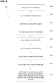
FIG. 3 is a schematic representation of a method for determining a fluid level. -
FIG. 4 is a schematic representation of an alternate embodiment of an electro-optic fluid level assembly. -
FIG. 5 is a schematic representation of an alternate method for determining a fluid level. - Reference will now be made in detail to the exemplary aspects of the present disclosure that are illustrated in the accompanying drawings. Wherever possible, the same reference numbers will be used throughout the drawings to refer to the same or like structure.
- Referring now to
FIG. 1 , an electro-opticfluid level sensor 10 is shown. The electro-opticfluid level sensor 10 is adapted to measure a continuous level of fluid in a fluid chamber. The electro-opticfluid level sensor 10 includes abody 12 having afirst end portion 14 and an oppositely disposedsecond end portion 16. Thebody 12 includes anouter surface 18 and aninner surface 20. Theinner surface 20 of thebody 12 defines acentral bore 22. In the depicted embodiment, thecentral bore 22 defines a centrallongitudinal axis 24 that extends through the first andsecond end portions - The
central bore 22 of thebody 12 is adapted to receive fluid through an opening 26 defined in thebody 12. In the depicted embodiment, thebody 12 defines a plurality ofopenings 26 that extends through the outer andinner surfaces body 12. - The electro-optic
fluid level sensor 10 includes alight source 30. In one embodiment, thelight source 30 is a light-emitting-diode (LED). In another embodiment, thelight source 30 is a plurality of LEDs. In the depicted embodiment, thelight source 30 is a laser. Thelight source 30 is disposed at thefirst end portion 14 of thebody 12. Thelight source 30 is disposed on thebody 12 so that thelight source 30 emits light 32 into thecentral bore 22 of thebody 12. In the depicted embodiment, thelight source 30 emits light 32 in a direction that is generally parallel to the centrallongitudinal axis 24 of thebody 12. - The electro-optic
fluid level sensor 10 further includes alight detector assembly 40 that includes a plurality of light detectors 42. In one embodiment, the light detectors 42 are photodiodes. In another embodiment, the light detectors 42 are light detectors adapted to receive light from a fiber optic light source. - In the depicted embodiment of
FIG. 1 , the electro-opticfluid level sensor 10 includes afirst light detector 42a and a secondlight detector 42b. The first and secondlight detectors body 12 at thesecond end portion 16. The first and secondlight detectors light source 30 and output first and second outputs, respectively, that are proportionate to the amount or intensity of light 32 received from thelight source 30. In the depicted embodiment, the first and second outputs are first and second voltages V1, V2. In an alternate embodiment, the first and second outputs are first and second currents. - The first and second
light detectors second end portion 16 of thebody 12. The secondlight detector 42b is axially offset from thefirst light detector 42a by a fixed distance ΔH that is measured in a direction that is generally parallel to the centrallongitudinal axis 24 of thebody 12, with the fixed distance ΔH being greater than zero. In the depicted embodiment, the secondlight detector 42b is disposed at a greater distance from thelight source 30 than thefirst light detector 42a. - The electro-optic
fluid level sensor 10 further includes aprocessing unit 44. The processing unit is adapted to receive the outputs from the first and secondlight detectors - In operation, the electro-optic
fluid level sensor 10 is disposed in a fluid chamber. Fluid in the fluid chamber enters thecentral bore 22 of the electro-opticfluid level sensor 10 through theopening 26 in thebody 12. Thelight source 30 emits light 32 that passes through the fluid in thecentral bore 22 and is received at the first and secondlight detectors light detectors central bore 22 of the electro-opticfluid level sensor 10. As the amount of fluid in thecentral bore 22 increases, the amount or intensity of light received at the first and secondlight detectors central bore 22 changes. - In one embodiment, as the height of the fluid in the
central bore 22 of thebody 12 of the electro-opticfluid level sensor 10 increases, the amount of light detected by the first and secondlight detectors central bore 22 of thebody 12 of the electro-opticfluid level sensor 10 can be calculated using a mathematical function of the axial offset between the first and secondlight detectors light detectors light detectors - As the Beer-Lambert Law provides that the absorbance of light in a solution is directly proportional to the length of the light path through the solution, the calculation of the height of the fluid in the
body 12 of the electro-opticfluid level sensor 10 will be described herein as being a linear mathematical function for ease of description purposes. It will be understood, however, that the present disclosure is not limited to the mathematical function being linear. - In the present example, the
processing unit 44 can calculate the height H1 of the fluid relative to the first light detector 40a using the following equation: H1 = m∗V1, where H1 is the height of the fluid relative to thefirst light detector 42a, V1 is the first voltage from the first light detector 40a and m is a constant equal to the change in height over the change in voltage. - As the electro-optic
fluid level sensor 10 has first and secondlight detectors light detectors first light detector 42a and the second voltage V2 of the second light detector 40b (ΔV = V1-V2). As the first and second voltages V1 and V2 are known from the first and second light detectors 40a, 40b and the fixed distance ΔH is known, the H1 value can be calculated. - Referring now to
FIG. 2 , an alternate embodiment of an electro-optic fluidlevel sensor assembly 100 is shown. The electro-optic fluidlevel sensor assembly 100 includes an electro-opticfluid level sensor 110. The electro-opticfluid level sensor 110 includes a body 112 having afirst end portion 114 and an oppositely disposedsecond end portion 116. The electro-opticfluid level sensor 110 defines a centrallongitudinal axis 124 that extends through the first andsecond end portions fluid level sensor 110 further includes alight source 130 disposed at thefirst end portion 114 and alight detector assembly 140 disposed at thesecond end portion 116. In the depicted embodiment, thelight source 130 is a laser. - The
light detector assembly 140 includes afirst light detector 142a and a secondlight detector 142b. The first and secondlight detectors first light detector 142a is disposed closer to thelight source 130 than the secondlight detector 142b in a direction that is parallel to the centrallongitudinal axis 124. - The electro-optic
fluid level assembly 100 further includes anelectronic module assembly 150. Theelectronic module assembly 150 is connected to the electro-opticfluid level sensor 110 by a fiberoptic cable assembly 152. The fiberoptic cable assembly 152 provides a communication pathway between the electro-opticfluid level sensor 110 and theelectronic module assembly 150. In one embodiment, the fiberoptic cable assembly 152 include a plurality of fiber optic cables and a plurality of fiber optic connectors. The use of fiberoptic cable assembly 152 creates an intrinsically safe electro-optic fluidlevel sensor assembly 100 that would allow the electro-optic fluidlevel sensor assembly 100 to be used with various fluids, including flammable fluids. - The electro-optic
fluid level sensor 110 is disposed in afluid chamber 160. In the depicted embodiment, thefluid chamber 160 is fuel tank that is adapted to receive a volatile, explosive and/or flammable liquid such as fuel. In the depicted embodiment, the fiberoptic cable assembly 152 is connected to the electro-opticfluid level sensor 110 through awall 162 in thefluid chamber 160. In one embodiment, the connection of the fiberoptic cable assembly 152 to the electro-opticfluid level sensor 110 may be through a hermetically sealed connector or a hermetically sealed pass-through. - The
electronic module assembly 150 is disposed outside thefluid chamber 160. In one embodiment, theelectronic module assembly 150 is disposed a safe distance from thefluid chamber 160. Theelectronic module assembly 150 is adapted to receive information signals (e.g., amount or intensity of light received at the first and secondlight detectors light sensor 110 through the fiberoptic cable assembly 152. In the depicted embodiment, theelectronic module assembly 150 is in communication with aprocessing unit 144. - Referring now to
FIGS. 1-3 , amethod 200 for determining the level of fluid in the electro-opticfluid level sensor step 202, thelight source longitudinal axis step 204, light is received at the first and second light detectors 42, 142. Instep 206, thefirst light detector first light detector light detector light detector step 208, theprocessing unit 144 computes the height of a fluid in thefluid chamber 160 based on the axial offset of the first and second light detectors 42, 142 and the first and second outputs. - Referring now to
FIG. 4 , an alternate embodiment of an electro-opticfluid level sensor 310 is shown. The electro-opticfluid level sensor 310 includes abody 312 having afirst end portion 314 and an oppositely disposedsecond end portion 316. Thebody 312 includes anouter surface 318 and aninner surface 320. Theinner surface 320 of thebody 312 defines acentral bore 322. In the depicted embodiment, thecentral bore 322 defines a centrallongitudinal axis 324 that extends through the first andsecond end portions - The
central bore 322 of thebody 312 defines anopening 326 in thebody 312. In the depicted embodiment, thebody 312 defines a plurality ofopenings 326 that extends through the outer andinner surfaces body 312. - In the depicted embodiment, the electro-optic
fluid level sensor 310 includes afirst light source 330a and a secondlight source 330b. In one embodiment, the first and secondlight sources light sources light sources light sources second end portion 316 of thebody 312. The first and secondlight sources body 312 so that the first and secondlight sources central bore 322 of thebody 312. In the depicted embodiment, the first and secondlight sources body 312 to emit light 332 in a direction that is generally parallel to the centrallongitudinal axis 324 of thebody 312. The secondlight source 330b is axially offset from thefirst light source 330a by a fixed distance ΔH that is measured in a direction that is generally parallel to the centrallongitudinal axis 324 of thebody 312, with the fixed distance ΔH being greater than zero. - The electro-optic
fluid level sensor 310 further includes a light detector assembly 340 that includes alight detector 342. In one embodiment, thelight detector 342 is a photodiode. In another embodiment, thelight detector 342 is adapted to receive light from a plurality of fiber optic light sources. - In the depicted embodiment of
FIG. 4 , the electro-opticfluid level sensor 310 includes thelight detector 342. Thelight detector 342 is disposed on thebody 312 at thefirst end portion 314. Thelight detector 342 is adapted to receive the light 332 emitted from the first and secondlight sources light 332 received from the first and secondlight sources light detector 342 is disposed at a greater distance from the secondlight source 330b than the firstlight source 330b. - The first and second voltages V1, V2 are transmitted to a
processing unit 344. Theprocessing unit 344 calculates the height of the fluid in thecentral bore 322 of the electro-opticfluid level sensor 310. The height of the fluid in thecentral bore 322 of thebody 312 of the electro-opticfluid level sensor 310 is a function of the axial offset ΔH between the first and secondlight sources light detector 342. In one embodiment, this function is linear. As the amount of light detected by the first and second light detectors 342a, 342b decreases, the first and second voltages V1, V2 decrease proportionally. In another embodiment, this function is logarithmic. - Referring now to
FIGS. 4 and5 , amethod 400 for determining the level of fluid in the electro-opticfluid level sensor 310 will be described. Instep 402, thefirst light source 330a disposed in the electro-opticfluid level sensor 310 emits light in a direction that is parallel to the centrallongitudinal axis 324. Instep 404, the emitted light from thefirst light source 330a is received at thelight detector 342. Instep 406, thelight detector 342 outputs a first output that is proportional to the amount or intensity of light from thefirst light source 330a received at thelight detector 342. Instep 408, thefirst light source 330a stops emitting light. Instep 410, the secondlight source 330b emits light in a direction that is parallel to the centrallongitudinal axis 324 of the electro-opticfluid level sensor 310. Instep 412, the emitted light from the secondlight source 330b is received at thelight detector 342. Instep 414, thelight detector 342 outputs a second output that is proportional to the amount or intensity of light from the secondlight source 330b received at thelight detector 342. In one embodiment, the first and second outputs are first and second voltages. Instep 416, the secondlight source 330b stops emitting light. Instep 418, a processing unit computes the height of a fluid in thecentral bore 322 using a fluid height equation. The fluid height equation is a mathematical function of the axial offset of the first and secondlight sources - Various modifications and alterations of this disclosure will become apparent to those skilled in the art without departing from the scope and spirit of this disclosure, and it should be understood that the scope of this disclosure is not to be unduly limited to the illustrative embodiments set forth herein.
Claims (14)
- An electro-optic continuous fluid level sensor comprising:a body having a first end portion and an oppositely disposed second end portion, the body defining a central bore and a central longitudinal axis, the central bore adapted to receive a fluid;a light source disposed at the first end portion of the body, the light source being aligned with the central longitudinal axis, wherein the light source emits light in a direction that is generally parallel with the central longitudinal axis;a light detector assembly disposed at the second end portion of the body and adapted to receive light emitted from the light source, the light detector assembly including a first light detector and a second light detector, wherein the second light detector is axially offset from the first light detector in a direction that is generally parallel with the central longitudinal axis.
- The electro-optic continuous fluid level sensor of claim 1, wherein the first light detector outputs a first output that is proportionate to an amount or intensity of light received at the first light detector from the light source.
- The electro-optic continuous fluid level sensor of claim 2, wherein the second light detector outputs a second output that is proportionate to an amount or intensity of light received at the second light detector from the light source.
- The electro-optic continuous fluid level sensor of claim 3, wherein the electro-optic fluid level sensor further includes a processing unit.
- The electro-optic continuous fluid level sensor of claim 4, wherein the processing unit is adapted to calculate a height of fluid in the central bore using a mathematical function of the offset of the first and second light detectors and the first and second outputs.
- The electro-optic continuous fluid level sensor of claim 5, wherein the mathematical function is logarithmic.
- A method for determining a fluid level in a fluid chamber, the method comprising the steps of:emitting light from a light source disposed in an electro-optic fluid level sensor;receiving the light at a first light detector of the electro-optic fluid level sensor, wherein the first light detector outputs a first output that is proportional to an amount of light the first light detector receives;receiving the light at a second light detector of the electro-optic fluid level sensor, the second light detector being axially offset a distance from the first light detector, wherein the second light detector outputs a second output that is proportional to an amount of light the second light detector receives; andcomputing a height of a fluid relative to the first light detector, wherein the height of the fluid computation is a mathematical function of a distance of the axial offset and the first and second outputs.
- A method for determining a fluid level in a fluid chamber as claimed in claim 7, wherein the first output is a first voltage.
- A method for determining a fluid level in a fluid chamber as claimed in claim 8, wherein the second output is a second voltage.
- A method for determining a fluid level in a fluid chamber as claimed in claim 7, wherein the mathematical function is linear.
- A method for determining a fluid level in a fluid chamber, the method comprising the steps of:emitting light from a first light source disposed in an electro-optic fluid level sensor;receiving the light at a light detector of the electro-optic fluid level sensor, wherein the light detector outputs a first output that is proportional to an amount of light the light detector receives from the first light source;emitting light from a second light source disposed in the electro-optic fluid level sensor, wherein the second light source is axially offset a distance from the first light source;receiving the light at the light detector, wherein the light detector outputs a second output that is proportional to an amount of light the light detector receives from the second light source;calculating a height of a fluid, wherein the height of the fluid calculation is a mathematical function of the distance of the axial offset between the first and second light sources and the first and second outputs.
- A method for determining a fluid level in a fluid chamber as claimed in claim 11, wherein the first output is a first voltage.
- A method for determining a fluid level in a fluid chamber as claimed in claim 12, wherein the second output is a second voltage.
- A method for determining a fluid level in a fluid chamber as claimed in claim 11, wherein the mathematical function is linear.
Applications Claiming Priority (1)
| Application Number | Priority Date | Filing Date | Title |
|---|---|---|---|
| US201862746013P | 2018-10-16 | 2018-10-16 |
Publications (2)
| Publication Number | Publication Date |
|---|---|
| EP3640607A1 true EP3640607A1 (en) | 2020-04-22 |
| EP3640607B1 EP3640607B1 (en) | 2022-01-19 |
Family
ID=68281253
Family Applications (1)
| Application Number | Title | Priority Date | Filing Date |
|---|---|---|---|
| EP19203710.9A Active EP3640607B1 (en) | 2018-10-16 | 2019-10-16 | Continuous electro-optic fluid level sensor |
Country Status (2)
| Country | Link |
|---|---|
| US (1) | US11268844B2 (en) |
| EP (1) | EP3640607B1 (en) |
Families Citing this family (1)
| Publication number | Priority date | Publication date | Assignee | Title |
|---|---|---|---|---|
| US20230236058A1 (en) * | 2022-01-21 | 2023-07-27 | Eaton Intelligent Power Limited | Methods and systems for testing electro optic sensors |
Citations (6)
| Publication number | Priority date | Publication date | Assignee | Title |
|---|---|---|---|---|
| US4443699A (en) * | 1979-08-31 | 1984-04-17 | The Johns Hopkins University | Fluid level measuring device with linear, high resolution output |
| US4762420A (en) * | 1986-04-01 | 1988-08-09 | Fisons Plc | Photometric reading device for serological analysis |
| US5073720A (en) * | 1990-07-30 | 1991-12-17 | The United States Of America As Represented By The Secretary Of The Navy | Liquid level and volume measurement device |
| US5303586A (en) * | 1993-01-22 | 1994-04-19 | Wayne State University | Pressure or fluid level sensor |
| DE102006014277A1 (en) * | 2006-03-23 | 2007-09-27 | M.U.T Aviation-Technology Gmbh | Apparatus and method for the continuous optical determination of the level of liquids in liquid storage tanks of vehicles or aircraft |
| DE102009050198A1 (en) * | 2009-10-21 | 2011-04-28 | Medizin & Service Gmbh | Method for measuring concentration of gaseous and fluid material and optical power of lamp based on Lambert-Beer's law, involves providing photoreceivers at variable distance to optical source |
Family Cites Families (8)
| Publication number | Priority date | Publication date | Assignee | Title |
|---|---|---|---|---|
| US4778990A (en) * | 1987-02-06 | 1988-10-18 | Varo, Inc. | Radiant energy receiving and directing apparatus and method |
| US5534708A (en) | 1993-12-15 | 1996-07-09 | Simmonds Precision Products Inc. | Optical fuel/air/water sensor and detector circuit |
| US6668645B1 (en) | 2002-06-18 | 2003-12-30 | Ti Group Automotive Systems, L.L.C. | Optical fuel level sensor |
| EP1382946A1 (en) | 2002-07-15 | 2004-01-21 | Product Innovation Limited | Level sensors |
| US7049622B1 (en) * | 2004-04-09 | 2006-05-23 | Sandia Corporation | Optical position sensor for determining the interface between a clear and an opaque fluid |
| US10620032B2 (en) | 2013-09-10 | 2020-04-14 | Eaton Intelligent Power Limited | Electro-optic liquid sensor with the use of reflected residual light to enable a test of the sensor |
| WO2015038514A1 (en) | 2013-09-10 | 2015-03-19 | Eaton Corporation | Electro-optic liquid sensor enabling in-liquid testing |
| US10371559B2 (en) | 2017-04-17 | 2019-08-06 | The Boeing Company | Differential spectral liquid level sensor |
-
2019
- 2019-10-14 US US16/600,861 patent/US11268844B2/en active Active
- 2019-10-16 EP EP19203710.9A patent/EP3640607B1/en active Active
Patent Citations (6)
| Publication number | Priority date | Publication date | Assignee | Title |
|---|---|---|---|---|
| US4443699A (en) * | 1979-08-31 | 1984-04-17 | The Johns Hopkins University | Fluid level measuring device with linear, high resolution output |
| US4762420A (en) * | 1986-04-01 | 1988-08-09 | Fisons Plc | Photometric reading device for serological analysis |
| US5073720A (en) * | 1990-07-30 | 1991-12-17 | The United States Of America As Represented By The Secretary Of The Navy | Liquid level and volume measurement device |
| US5303586A (en) * | 1993-01-22 | 1994-04-19 | Wayne State University | Pressure or fluid level sensor |
| DE102006014277A1 (en) * | 2006-03-23 | 2007-09-27 | M.U.T Aviation-Technology Gmbh | Apparatus and method for the continuous optical determination of the level of liquids in liquid storage tanks of vehicles or aircraft |
| DE102009050198A1 (en) * | 2009-10-21 | 2011-04-28 | Medizin & Service Gmbh | Method for measuring concentration of gaseous and fluid material and optical power of lamp based on Lambert-Beer's law, involves providing photoreceivers at variable distance to optical source |
Also Published As
| Publication number | Publication date |
|---|---|
| US20200116544A1 (en) | 2020-04-16 |
| US11268844B2 (en) | 2022-03-08 |
| EP3640607B1 (en) | 2022-01-19 |
Similar Documents
| Publication | Publication Date | Title |
|---|---|---|
| US9863244B2 (en) | Downhole fluid properties analysis probe, tool and method | |
| US5073720A (en) | Liquid level and volume measurement device | |
| TWI868100B (en) | Non-contact time-of-flight fuel level sensor using plastic optical fiber | |
| US8695420B1 (en) | Liquid level sensing system | |
| KR102392601B1 (en) | Dust sensor | |
| US6668645B1 (en) | Optical fuel level sensor | |
| JPS6237333B2 (en) | ||
| EP2553434A2 (en) | Fluorometric sensor | |
| EP3640607B1 (en) | Continuous electro-optic fluid level sensor | |
| US7497021B2 (en) | Multi-axis bubble vial device | |
| US6693285B1 (en) | Fluorescent fluid interface position sensor | |
| SE440150B (en) | DEVICE FOR OPTICAL SEATING OF THE MOVEMENT OF A FORMAL | |
| US10451518B2 (en) | All fiber temperature and air density sensor | |
| EP3472596B1 (en) | Turbidity sensor and method for measuring turbidity | |
| US11293799B2 (en) | Chromatic confocal sensor | |
| RU2707979C1 (en) | Hydrostatic fiber-optic liquid level sensor with position-sensitive detector | |
| US8362436B1 (en) | Electro-optic fluid quantity measurement system | |
| US5606125A (en) | Material level-interface control system | |
| RU2697033C1 (en) | Explosion-proof fiber-optic level gauge | |
| KR102216721B1 (en) | weight detecting apparatus using optical fiber sensor cable | |
| CN105180815B (en) | Self-referencing, intensity-based polymer optical fiber displacement sensor | |
| JP2023534491A (en) | Rotor system and related equipment for measuring the flow rate of fluids, including liquids | |
| US7385215B2 (en) | Sensor elements for supercavitating vehicles | |
| US12596038B2 (en) | Distributed temperature sensing system with fiber Bragg gratings | |
| LU103097B1 (en) | Optical fluid verification for air bubble detection in fluid filled hoses |
Legal Events
| Date | Code | Title | Description |
|---|---|---|---|
| PUAI | Public reference made under article 153(3) epc to a published international application that has entered the european phase |
Free format text: ORIGINAL CODE: 0009012 |
|
| STAA | Information on the status of an ep patent application or granted ep patent |
Free format text: STATUS: REQUEST FOR EXAMINATION WAS MADE |
|
| 17P | Request for examination filed |
Effective date: 20191016 |
|
| AK | Designated contracting states |
Kind code of ref document: A1 Designated state(s): AL AT BE BG CH CY CZ DE DK EE ES FI FR GB GR HR HU IE IS IT LI LT LU LV MC MK MT NL NO PL PT RO RS SE SI SK SM TR |
|
| AX | Request for extension of the european patent |
Extension state: BA ME |
|
| GRAP | Despatch of communication of intention to grant a patent |
Free format text: ORIGINAL CODE: EPIDOSNIGR1 |
|
| STAA | Information on the status of an ep patent application or granted ep patent |
Free format text: STATUS: GRANT OF PATENT IS INTENDED |
|
| GRAJ | Information related to disapproval of communication of intention to grant by the applicant or resumption of examination proceedings by the epo deleted |
Free format text: ORIGINAL CODE: EPIDOSDIGR1 |
|
| STAA | Information on the status of an ep patent application or granted ep patent |
Free format text: STATUS: REQUEST FOR EXAMINATION WAS MADE |
|
| INTG | Intention to grant announced |
Effective date: 20210401 |
|
| INTC | Intention to grant announced (deleted) | ||
| STAA | Information on the status of an ep patent application or granted ep patent |
Free format text: STATUS: EXAMINATION IS IN PROGRESS |
|
| 17Q | First examination report despatched |
Effective date: 20210526 |
|
| GRAP | Despatch of communication of intention to grant a patent |
Free format text: ORIGINAL CODE: EPIDOSNIGR1 |
|
| STAA | Information on the status of an ep patent application or granted ep patent |
Free format text: STATUS: GRANT OF PATENT IS INTENDED |
|
| INTG | Intention to grant announced |
Effective date: 20210721 |
|
| GRAS | Grant fee paid |
Free format text: ORIGINAL CODE: EPIDOSNIGR3 |
|
| GRAA | (expected) grant |
Free format text: ORIGINAL CODE: 0009210 |
|
| STAA | Information on the status of an ep patent application or granted ep patent |
Free format text: STATUS: THE PATENT HAS BEEN GRANTED |
|
| AK | Designated contracting states |
Kind code of ref document: B1 Designated state(s): AL AT BE BG CH CY CZ DE DK EE ES FI FR GB GR HR HU IE IS IT LI LT LU LV MC MK MT NL NO PL PT RO RS SE SI SK SM TR |
|
| REG | Reference to a national code |
Ref country code: GB Ref legal event code: FG4D |
|
| REG | Reference to a national code |
Ref country code: CH Ref legal event code: EP |
|
| REG | Reference to a national code |
Ref country code: DE Ref legal event code: R096 Ref document number: 602019011013 Country of ref document: DE |
|
| REG | Reference to a national code |
Ref country code: AT Ref legal event code: REF Ref document number: 1464058 Country of ref document: AT Kind code of ref document: T Effective date: 20220215 |
|
| REG | Reference to a national code |
Ref country code: IE Ref legal event code: FG4D |
|
| REG | Reference to a national code |
Ref country code: LT Ref legal event code: MG9D |
|
| REG | Reference to a national code |
Ref country code: NL Ref legal event code: MP Effective date: 20220119 |
|
| REG | Reference to a national code |
Ref country code: AT Ref legal event code: MK05 Ref document number: 1464058 Country of ref document: AT Kind code of ref document: T Effective date: 20220119 |
|
| PG25 | Lapsed in a contracting state [announced via postgrant information from national office to epo] |
Ref country code: NL Free format text: LAPSE BECAUSE OF FAILURE TO SUBMIT A TRANSLATION OF THE DESCRIPTION OR TO PAY THE FEE WITHIN THE PRESCRIBED TIME-LIMIT Effective date: 20220119 |
|
| PG25 | Lapsed in a contracting state [announced via postgrant information from national office to epo] |
Ref country code: SE Free format text: LAPSE BECAUSE OF FAILURE TO SUBMIT A TRANSLATION OF THE DESCRIPTION OR TO PAY THE FEE WITHIN THE PRESCRIBED TIME-LIMIT Effective date: 20220119 Ref country code: RS Free format text: LAPSE BECAUSE OF FAILURE TO SUBMIT A TRANSLATION OF THE DESCRIPTION OR TO PAY THE FEE WITHIN THE PRESCRIBED TIME-LIMIT Effective date: 20220119 Ref country code: PT Free format text: LAPSE BECAUSE OF FAILURE TO SUBMIT A TRANSLATION OF THE DESCRIPTION OR TO PAY THE FEE WITHIN THE PRESCRIBED TIME-LIMIT Effective date: 20220519 Ref country code: NO Free format text: LAPSE BECAUSE OF FAILURE TO SUBMIT A TRANSLATION OF THE DESCRIPTION OR TO PAY THE FEE WITHIN THE PRESCRIBED TIME-LIMIT Effective date: 20220419 Ref country code: LT Free format text: LAPSE BECAUSE OF FAILURE TO SUBMIT A TRANSLATION OF THE DESCRIPTION OR TO PAY THE FEE WITHIN THE PRESCRIBED TIME-LIMIT Effective date: 20220119 Ref country code: HR Free format text: LAPSE BECAUSE OF FAILURE TO SUBMIT A TRANSLATION OF THE DESCRIPTION OR TO PAY THE FEE WITHIN THE PRESCRIBED TIME-LIMIT Effective date: 20220119 Ref country code: ES Free format text: LAPSE BECAUSE OF FAILURE TO SUBMIT A TRANSLATION OF THE DESCRIPTION OR TO PAY THE FEE WITHIN THE PRESCRIBED TIME-LIMIT Effective date: 20220119 Ref country code: BG Free format text: LAPSE BECAUSE OF FAILURE TO SUBMIT A TRANSLATION OF THE DESCRIPTION OR TO PAY THE FEE WITHIN THE PRESCRIBED TIME-LIMIT Effective date: 20220419 |
|
| PG25 | Lapsed in a contracting state [announced via postgrant information from national office to epo] |
Ref country code: PL Free format text: LAPSE BECAUSE OF FAILURE TO SUBMIT A TRANSLATION OF THE DESCRIPTION OR TO PAY THE FEE WITHIN THE PRESCRIBED TIME-LIMIT Effective date: 20220119 Ref country code: LV Free format text: LAPSE BECAUSE OF FAILURE TO SUBMIT A TRANSLATION OF THE DESCRIPTION OR TO PAY THE FEE WITHIN THE PRESCRIBED TIME-LIMIT Effective date: 20220119 Ref country code: GR Free format text: LAPSE BECAUSE OF FAILURE TO SUBMIT A TRANSLATION OF THE DESCRIPTION OR TO PAY THE FEE WITHIN THE PRESCRIBED TIME-LIMIT Effective date: 20220420 Ref country code: FI Free format text: LAPSE BECAUSE OF FAILURE TO SUBMIT A TRANSLATION OF THE DESCRIPTION OR TO PAY THE FEE WITHIN THE PRESCRIBED TIME-LIMIT Effective date: 20220119 Ref country code: AT Free format text: LAPSE BECAUSE OF FAILURE TO SUBMIT A TRANSLATION OF THE DESCRIPTION OR TO PAY THE FEE WITHIN THE PRESCRIBED TIME-LIMIT Effective date: 20220119 |
|
| PG25 | Lapsed in a contracting state [announced via postgrant information from national office to epo] |
Ref country code: IS Free format text: LAPSE BECAUSE OF FAILURE TO SUBMIT A TRANSLATION OF THE DESCRIPTION OR TO PAY THE FEE WITHIN THE PRESCRIBED TIME-LIMIT Effective date: 20220519 |
|
| REG | Reference to a national code |
Ref country code: DE Ref legal event code: R097 Ref document number: 602019011013 Country of ref document: DE |
|
| PG25 | Lapsed in a contracting state [announced via postgrant information from national office to epo] |
Ref country code: SM Free format text: LAPSE BECAUSE OF FAILURE TO SUBMIT A TRANSLATION OF THE DESCRIPTION OR TO PAY THE FEE WITHIN THE PRESCRIBED TIME-LIMIT Effective date: 20220119 Ref country code: SK Free format text: LAPSE BECAUSE OF FAILURE TO SUBMIT A TRANSLATION OF THE DESCRIPTION OR TO PAY THE FEE WITHIN THE PRESCRIBED TIME-LIMIT Effective date: 20220119 Ref country code: RO Free format text: LAPSE BECAUSE OF FAILURE TO SUBMIT A TRANSLATION OF THE DESCRIPTION OR TO PAY THE FEE WITHIN THE PRESCRIBED TIME-LIMIT Effective date: 20220119 Ref country code: EE Free format text: LAPSE BECAUSE OF FAILURE TO SUBMIT A TRANSLATION OF THE DESCRIPTION OR TO PAY THE FEE WITHIN THE PRESCRIBED TIME-LIMIT Effective date: 20220119 Ref country code: DK Free format text: LAPSE BECAUSE OF FAILURE TO SUBMIT A TRANSLATION OF THE DESCRIPTION OR TO PAY THE FEE WITHIN THE PRESCRIBED TIME-LIMIT Effective date: 20220119 Ref country code: CZ Free format text: LAPSE BECAUSE OF FAILURE TO SUBMIT A TRANSLATION OF THE DESCRIPTION OR TO PAY THE FEE WITHIN THE PRESCRIBED TIME-LIMIT Effective date: 20220119 |
|
| PLBE | No opposition filed within time limit |
Free format text: ORIGINAL CODE: 0009261 |
|
| STAA | Information on the status of an ep patent application or granted ep patent |
Free format text: STATUS: NO OPPOSITION FILED WITHIN TIME LIMIT |
|
| PG25 | Lapsed in a contracting state [announced via postgrant information from national office to epo] |
Ref country code: AL Free format text: LAPSE BECAUSE OF FAILURE TO SUBMIT A TRANSLATION OF THE DESCRIPTION OR TO PAY THE FEE WITHIN THE PRESCRIBED TIME-LIMIT Effective date: 20220119 |
|
| 26N | No opposition filed |
Effective date: 20221020 |
|
| PG25 | Lapsed in a contracting state [announced via postgrant information from national office to epo] |
Ref country code: SI Free format text: LAPSE BECAUSE OF FAILURE TO SUBMIT A TRANSLATION OF THE DESCRIPTION OR TO PAY THE FEE WITHIN THE PRESCRIBED TIME-LIMIT Effective date: 20220119 |
|
| PG25 | Lapsed in a contracting state [announced via postgrant information from national office to epo] |
Ref country code: MC Free format text: LAPSE BECAUSE OF FAILURE TO SUBMIT A TRANSLATION OF THE DESCRIPTION OR TO PAY THE FEE WITHIN THE PRESCRIBED TIME-LIMIT Effective date: 20220119 |
|
| REG | Reference to a national code |
Ref country code: CH Ref legal event code: PL |
|
| REG | Reference to a national code |
Ref country code: BE Ref legal event code: MM Effective date: 20221031 |
|
| P01 | Opt-out of the competence of the unified patent court (upc) registered |
Effective date: 20230521 |
|
| PG25 | Lapsed in a contracting state [announced via postgrant information from national office to epo] |
Ref country code: LU Free format text: LAPSE BECAUSE OF NON-PAYMENT OF DUE FEES Effective date: 20221016 |
|
| PG25 | Lapsed in a contracting state [announced via postgrant information from national office to epo] |
Ref country code: LI Free format text: LAPSE BECAUSE OF NON-PAYMENT OF DUE FEES Effective date: 20221031 Ref country code: IT Free format text: LAPSE BECAUSE OF FAILURE TO SUBMIT A TRANSLATION OF THE DESCRIPTION OR TO PAY THE FEE WITHIN THE PRESCRIBED TIME-LIMIT Effective date: 20220119 Ref country code: CH Free format text: LAPSE BECAUSE OF NON-PAYMENT OF DUE FEES Effective date: 20221031 |
|
| PG25 | Lapsed in a contracting state [announced via postgrant information from national office to epo] |
Ref country code: BE Free format text: LAPSE BECAUSE OF NON-PAYMENT OF DUE FEES Effective date: 20221031 |
|
| PG25 | Lapsed in a contracting state [announced via postgrant information from national office to epo] |
Ref country code: IE Free format text: LAPSE BECAUSE OF NON-PAYMENT OF DUE FEES Effective date: 20221016 |
|
| PG25 | Lapsed in a contracting state [announced via postgrant information from national office to epo] |
Ref country code: HU Free format text: LAPSE BECAUSE OF FAILURE TO SUBMIT A TRANSLATION OF THE DESCRIPTION OR TO PAY THE FEE WITHIN THE PRESCRIBED TIME-LIMIT; INVALID AB INITIO Effective date: 20191016 |
|
| PG25 | Lapsed in a contracting state [announced via postgrant information from national office to epo] |
Ref country code: CY Free format text: LAPSE BECAUSE OF FAILURE TO SUBMIT A TRANSLATION OF THE DESCRIPTION OR TO PAY THE FEE WITHIN THE PRESCRIBED TIME-LIMIT Effective date: 20220119 |
|
| PG25 | Lapsed in a contracting state [announced via postgrant information from national office to epo] |
Ref country code: MK Free format text: LAPSE BECAUSE OF FAILURE TO SUBMIT A TRANSLATION OF THE DESCRIPTION OR TO PAY THE FEE WITHIN THE PRESCRIBED TIME-LIMIT Effective date: 20220119 |
|
| GBPC | Gb: european patent ceased through non-payment of renewal fee |
Effective date: 20231016 |
|
| PG25 | Lapsed in a contracting state [announced via postgrant information from national office to epo] |
Ref country code: TR Free format text: LAPSE BECAUSE OF FAILURE TO SUBMIT A TRANSLATION OF THE DESCRIPTION OR TO PAY THE FEE WITHIN THE PRESCRIBED TIME-LIMIT Effective date: 20220119 |
|
| PG25 | Lapsed in a contracting state [announced via postgrant information from national office to epo] |
Ref country code: GB Free format text: LAPSE BECAUSE OF NON-PAYMENT OF DUE FEES Effective date: 20231016 |
|
| PG25 | Lapsed in a contracting state [announced via postgrant information from national office to epo] |
Ref country code: GB Free format text: LAPSE BECAUSE OF NON-PAYMENT OF DUE FEES Effective date: 20231016 |
|
| PG25 | Lapsed in a contracting state [announced via postgrant information from national office to epo] |
Ref country code: MT Free format text: LAPSE BECAUSE OF FAILURE TO SUBMIT A TRANSLATION OF THE DESCRIPTION OR TO PAY THE FEE WITHIN THE PRESCRIBED TIME-LIMIT Effective date: 20220119 |
|
| PGFP | Annual fee paid to national office [announced via postgrant information from national office to epo] |
Ref country code: FR Payment date: 20250924 Year of fee payment: 7 |
|
| PGFP | Annual fee paid to national office [announced via postgrant information from national office to epo] |
Ref country code: DE Payment date: 20250923 Year of fee payment: 7 |