EP3640593A1 - Position detecting device and position detecting method - Google Patents
Position detecting device and position detecting method Download PDFInfo
- Publication number
- EP3640593A1 EP3640593A1 EP18818319.8A EP18818319A EP3640593A1 EP 3640593 A1 EP3640593 A1 EP 3640593A1 EP 18818319 A EP18818319 A EP 18818319A EP 3640593 A1 EP3640593 A1 EP 3640593A1
- Authority
- EP
- European Patent Office
- Prior art keywords
- acceleration
- acceleration information
- information
- movement
- position detection
- Prior art date
- Legal status (The legal status is an assumption and is not a legal conclusion. Google has not performed a legal analysis and makes no representation as to the accuracy of the status listed.)
- Withdrawn
Links
- 238000000034 method Methods 0.000 title claims description 27
- 230000001133 acceleration Effects 0.000 claims abstract description 272
- 230000033001 locomotion Effects 0.000 claims abstract description 74
- 238000001514 detection method Methods 0.000 claims abstract description 60
- 230000003068 static effect Effects 0.000 claims abstract description 56
- 230000036461 convulsion Effects 0.000 claims description 8
- 230000010354 integration Effects 0.000 claims description 4
- 238000012886 linear function Methods 0.000 claims description 3
- 230000008859 change Effects 0.000 claims description 2
- 238000009434 installation Methods 0.000 description 13
- 230000008569 process Effects 0.000 description 12
- 238000005259 measurement Methods 0.000 description 11
- 238000010586 diagram Methods 0.000 description 6
- 238000012545 processing Methods 0.000 description 6
- 230000006870 function Effects 0.000 description 3
- 230000004807 localization Effects 0.000 description 2
- 238000007796 conventional method Methods 0.000 description 1
- 238000012937 correction Methods 0.000 description 1
- 238000009795 derivation Methods 0.000 description 1
- 230000000694 effects Effects 0.000 description 1
- 230000007613 environmental effect Effects 0.000 description 1
- 239000000284 extract Substances 0.000 description 1
- 238000012986 modification Methods 0.000 description 1
- 230000004048 modification Effects 0.000 description 1
- 238000003909 pattern recognition Methods 0.000 description 1
- 238000012887 quadratic function Methods 0.000 description 1
- 230000007704 transition Effects 0.000 description 1
Images

Classifications
-
- G—PHYSICS
- G01—MEASURING; TESTING
- G01C—MEASURING DISTANCES, LEVELS OR BEARINGS; SURVEYING; NAVIGATION; GYROSCOPIC INSTRUMENTS; PHOTOGRAMMETRY OR VIDEOGRAMMETRY
- G01C21/00—Navigation; Navigational instruments not provided for in groups G01C1/00 - G01C19/00
- G01C21/10—Navigation; Navigational instruments not provided for in groups G01C1/00 - G01C19/00 by using measurements of speed or acceleration
- G01C21/12—Navigation; Navigational instruments not provided for in groups G01C1/00 - G01C19/00 by using measurements of speed or acceleration executed aboard the object being navigated; Dead reckoning
- G01C21/16—Navigation; Navigational instruments not provided for in groups G01C1/00 - G01C19/00 by using measurements of speed or acceleration executed aboard the object being navigated; Dead reckoning by integrating acceleration or speed, i.e. inertial navigation
- G01C21/183—Compensation of inertial measurements, e.g. for temperature effects
-
- G—PHYSICS
- G01—MEASURING; TESTING
- G01C—MEASURING DISTANCES, LEVELS OR BEARINGS; SURVEYING; NAVIGATION; GYROSCOPIC INSTRUMENTS; PHOTOGRAMMETRY OR VIDEOGRAMMETRY
- G01C21/00—Navigation; Navigational instruments not provided for in groups G01C1/00 - G01C19/00
- G01C21/10—Navigation; Navigational instruments not provided for in groups G01C1/00 - G01C19/00 by using measurements of speed or acceleration
- G01C21/12—Navigation; Navigational instruments not provided for in groups G01C1/00 - G01C19/00 by using measurements of speed or acceleration executed aboard the object being navigated; Dead reckoning
- G01C21/16—Navigation; Navigational instruments not provided for in groups G01C1/00 - G01C19/00 by using measurements of speed or acceleration executed aboard the object being navigated; Dead reckoning by integrating acceleration or speed, i.e. inertial navigation
- G01C21/183—Compensation of inertial measurements, e.g. for temperature effects
- G01C21/188—Compensation of inertial measurements, e.g. for temperature effects for accumulated errors, e.g. by coupling inertial systems with absolute positioning systems
-
- G—PHYSICS
- G01—MEASURING; TESTING
- G01P—MEASURING LINEAR OR ANGULAR SPEED, ACCELERATION, DECELERATION, OR SHOCK; INDICATING PRESENCE, ABSENCE, OR DIRECTION, OF MOVEMENT
- G01P21/00—Testing or calibrating of apparatus or devices covered by the preceding groups
Definitions
- the present invention relates to a position detection device and a position detection method that use an acceleration sensor.
- a method for detecting a position of an apparatus by using an acceleration sensor is conventionally put into practical use. Further, to improve accuracy of position detection using an acceleration sensor, a method in which a global positioning system (GPS) or video information is additionally used is also proposed recently.
- GPS global positioning system
- the method in which position information acquired by a GPS or video information obtained by a camera or the like is combined with the technique of detecting a position by using an acceleration sensor in this way is used in a vehicle-mounted car navigation system, for example.
- Non Patent Literature 1 a method for detecting a position of an apparatus without using an acceleration sensor.
- a method for correcting position information acquired by a GPS by using image information acquired by a camera for example (refer to Non Patent Literature 1, for example).
- Non Patent Literature 2 a method using a laser transmitter is proposed (refer to Non Patent Literature 2, for example).
- a laser transmitter a plurality of laser transmitters are installed around the apparatus, and the position of the apparatus is detected based on information contained in radio waves transmitted and received between the device and the transmitters.
- the apparatus needs to be able to receive signals by the GPS. Accordingly, in the places where the signals of the GPS cannot be received, such as indoors or mountainous areas, the position cannot be detected. Further, in the case of using the image information acquired by a camera, position detection depends on environmental conditions such as ambient brightness and distance.
- Non Patent Literature 2 it is necessary to install laser transmitters around the apparatus. Accordingly, an environment in which the laser transmitters can be installed to detect the position is necessary. Further, since a plurality of laser transmitters are required, cost as the system increases.
- the present invention is made in the light of the problem in the above described conventional technique, and has an object to provide a position detection device and a position detection method that can enhance accuracy of position detection using an acceleration sensor without using information from outside.
- a position detection device is a position detection device installed in an apparatus, and detecting a position of the apparatus, and includes an acceleration sensor configured to detect acceleration information of the apparatus, a static acceleration removing unit configured to remove static acceleration information indicating acceleration information in a static state of the apparatus, from the acceleration information detected by the acceleration sensor, and generate movement acceleration information indicating acceleration information in a moving state of the apparatus, an error deriving unit configured to derive an error component contained in the movement acceleration information, an acceleration correcting unit configured to correct the movement acceleration information by subtracting the error component from the movement acceleration information, and a position information acquiring unit configured to acquire position information of the apparatus based on the corrected movement acceleration information.
- a position detection method is a position detection method detecting a position of an apparatus, and includes a step of detecting acceleration information of the apparatus, a step of removing static acceleration information indicating acceleration information in a static state of the apparatus, from the detected acceleration information, and generating movement acceleration information indicating acceleration information in a moving state of the apparatus, a step of deriving an error component contained in the movement acceleration information, a step of correcting the movement acceleration information by subtracting the error component from the movement acceleration information, and a step of acquiring position information of the apparatus, based on the corrected movement acceleration information.
- position information is acquired based on the acceleration information obtained by removing the error component from the acceleration information detected by the acceleration sensor, and thereby accuracy of position detection using the acceleration sensor can be enhanced without using information from outside.
- a position detection device according to embodiment 1 of the present invention will be described hereinafter.
- the position detection device according to embodiment 1 is used, for example, in a locator or the like for locating objects buried in the ground, and detects a position of an installation apparatus.
- the position detection device like this is used as an inertial navigation system that detects a position of the installation apparatus without using information obtained from outside, for example.
- Fig. 1 is a block diagram showing an example of a configuration of a position detection device 1 according to the present embodiment 1.
- the position detection device 1 includes an arithmetic device 10 and an acceleration sensor 20, and is installed in an installation apparatus such as a locator.
- the acceleration sensor 20 detects acceleration information in each of three axial directions orthogonal to one another at a preset timing, and supplies the acceleration information to the arithmetic device 10.
- the acceleration sensor 20 for example, a micro electro mechanical systems (MEMS) sensor is used.
- MEMS micro electro mechanical systems
- the arithmetic device 10 detects a position of the installation apparatus in which the position detection device 1 is installed, based on acceleration information received from the acceleration sensor 20, and generates position information indicating the position.
- the arithmetic device 10 is a microcomputer, for example, and is configured by hardware such as a read only memory (ROM), a random access memory (RAM), a nonvolatile memory, an input device, an output device and a storage device such as a hard disk drive (HDD), and program software executed on a microcomputer, and the like.
- the arithmetic device 10 and the acceleration sensor 20 are described to be integrally configured as the position detection device 1, but the position detection device 1 is not limited to the example.
- the arithmetic device 10 may be provided in an external apparatus such as a PC.
- the arithmetic device 10 and the acceleration sensor 2 are connected by wire or wirelessly.
- Fig. 2 is a functional block diagram showing an example of a configuration of the arithmetic device 10 in Fig. 1 .
- the arithmetic device 10 includes a static acceleration removing unit 11, an error deriving unit 12, an acceleration correcting unit 13 and a position information acquiring unit 14.
- the static acceleration removing unit 11 performs processing of removing acceleration information in a static state before and after movement of the installation apparatus, from acceleration information supplied from the acceleration sensor 20. Specifically, the static acceleration removing unit 11 removes static acceleration information that is acceleration information in a static state before the installation apparatus starts movement, and a static state after end of the movement. Subsequently, the static acceleration removing unit 11 extracts movement acceleration information that is acceleration information in a moving state of the installation apparatus.
- the error deriving unit 12 derives a trend that is an error component contained in the acceleration information, based on the movement acceleration information extracted in the static acceleration removing unit 11.
- the trend is an error component such as a direct current (DC) offset component caused by hysteresis that is a characteristic of the MEMS sensor when the MEMS sensor is used as the acceleration sensor 20, for example.
- DC direct current
- the acceleration correcting unit 13 performs processing of correcting the movement acceleration information based on the movement acceleration information extracted in the static acceleration removing unit 11, and the trend derived in the error deriving unit 12. Specifically, the acceleration correcting unit 13 subtracts the trend from the movement acceleration information, and thereby corrects the movement acceleration information.
- the position information acquiring unit 14 acquires position information indicating a position from a starting point of the acceleration sensor 20 provided in the installation apparatus, based on the movement acceleration information corrected in the acceleration correcting unit 13. Specifically, the position information acquiring unit 14 performs integration two times on the corrected movement acceleration information, and thereby acquires position information. At this time, the position information acquiring unit 14 uses position information on the starting point and an ending point of the acceleration sensor 20 that are set in advance.
- position information with high accuracy is acquired by removing an error component contained in the acceleration information, when the position information is acquired from the acceleration information detected by the acceleration sensor 20.
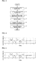
- Fig. 3 is a flowchart showing an example of a flow of the position detection process by the position detection device 1 in Fig. 1 .
- a case of detecting a position in any one axial direction of the three axial directions detected by the acceleration sensor 20 will be described by being taken as an example.
- the positions can be detected by performing a same process.
- a user who performs position detection moves the installation apparatus in which the acceleration sensor 20 is provided manually or automatically (step S1).
- the user disposes the installation apparatus in which the acceleration sensor 20 is provided in a position to be a starting point of position detection, and thereafter moves the installation apparatus so that the starting point becomes an ending point.
- the acceleration sensor 20 detects acceleration information at a set timing, and supplies the detected acceleration information to the static acceleration removing unit 11 of the arithmetic device 10 (step S2).
- “moving the installation equipment in which the acceleration sensor 20 is provided” will be described simply as “moving the acceleration sensor 20".
- the static acceleration removing unit 11 removes static acceleration information that is acceleration information in a static state before and after movement from the acceleration information detected by the acceleration sensor 20 (step S3).
- the acceleration information detected by the acceleration sensor 20 may also contain acceleration information in the static state before start of movement of the acceleration sensor 20 and after end of the movement.
- acceleration does not become “0" even when the acceleration sensor 20 is in a static state, and may indicate a value as if the acceleration sensor 20 is moving.
- the value of the acceleration in the static state becomes an error at a time of detecting a position, and becomes a cause of reducing detection accuracy. Therefore, in step S3, processing of removing the static acceleration information that is the acceleration information in the static state, from the acceleration information detected in the acceleration sensor 20 is performed.
- Determination of whether the acceleration sensor 20 is in a static state, or in a moving state is performed based on jerk in the acceleration information detected by the sensor. Jerk indicates a change amount of the acceleration per unit time. When the state transitions from a static state to a moving state, or from the moving state to the static state, for example, the acceleration changes greatly, and therefore the jerk has a large value.
- a range to be a threshold is set in advance to the jerk, and when the jerk is within a set range of the threshold, the acceleration sensor 20 can be determined as moving or stopping.
- the static acceleration removing unit 11 removes the static acceleration information from the acceleration information detected by the acceleration sensor 20, and generates movement acceleration information that is the acceleration information in the moving state.
- the error deriving unit 12 of the arithmetic device 10 performs processing of deriving a trend that is an error component contained in the acceleration information from the movement acceleration information (step S4).
- the acceleration correcting unit 13 of the arithmetic device 10 performs correction processing of the movement acceleration information based on the trend derived in the error deriving unit 12 (step S5).
- the movement acceleration information generated by the static acceleration removing unit 11 based on the acceleration information detected by the acceleration sensor 20 contains a trend that is an error component such as a DC offset to the acceleration caused by hysteresis as the characteristic of the MEMS sensor. Accordingly, an influence by the trend needs to be removed to detect the position of the acceleration sensor 20 accurately.
- the trend contains a direct-current component such as a DC offset, and a component changing gradually over time. Accordingly, the trend ⁇ (t) is defined by an approximate expression by a linear function or the like as in expression (2) here.
- the position information acquiring unit 14 of the arithmetic device 10 performs processing of acquiring position information based on the true acceleration information ⁇ (t) calculated in the acceleration correcting unit 13 (step S6).
- the position information can be calculated by performing integration two times on the true acceleration information ⁇ (t).
- the position information acquiring unit 14 calculates velocity information v(t) based on the calculated true acceleration information ⁇ (t).
- the velocity information v(t) can be obtained by integrating the true acceleration information ⁇ (t), and is calculated by expression (6).
- velocity information v(0) is an initial value, and indicates a velocity before start of measurement of the acceleration.
- velocity information v(T) at a time T when measurement of the acceleration by the acceleration sensor 20 is ended is calculated based on expression (7).
- the velocity information v(0) in expression (7) indicates a velocity before start of measurement of the acceleration as in expression (6).
- v T v 0 + ⁇ 0 T ⁇ t dt
- the acceleration sensor 20 since the acceleration sensor 20 is in a static state before start and after end of measurement of the acceleration in the present embodiment 1, the velocity information v(0) in expression (6) and expression (7), and the velocity information v(T) in expression (7) have values of "0". This is understandable from the fact that the direct-current component contained in the trend ⁇ (t) is removed from the movement acceleration information f(t) in expression (5).
- the position information acquiring unit 14 calculates position information x(t) based on the calculated velocity information v(t).
- the position information x(t) can be obtained by integrating the velocity information v(t), and can be calculated by expression (8).
- position information x(T) at the time T when measurement of the acceleration by the acceleration sensor 20 is ended is calculated based on expression (9).
- the position information x(0) in expression (9) indicates a position before start of measurement of the acceleration as in expression (8).
- the acceleration sensor 20 is moved so that the position before measurement of the acceleration and the position after measurement of the acceleration correspond to each other, and the movement acceleration information f(t) at this time is derived.
- the position information x(t) is acquired based on the true acceleration information ⁇ (t) obtained by removing the trend ⁇ (t) from the derived movement acceleration information f(t).
- various error factors contained in the acceleration information detected by the acceleration sensor 20 are removed, and therefore the position of the acceleration sensor 20 can be detected with high accuracy.
- Fig. 4 is a graph showing an example of the acceleration information detected by the acceleration sensor 20.
- Fig. 5 is a graph showing an example of the result that the static acceleration information is removed from the acceleration information in Fig. 4 .
- the static acceleration information is removed by the static acceleration removing unit 11, and thereby the static acceleration information on the states before and after movement is removed.
- the acceleration sensor 20 is considered to be in a static state.
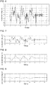
- Fig. 6 is a graph showing an example of a result that the trend is removed from the movement acceleration information.
- a graph shown by a solid line shows the movement acceleration information f(t) generated by the static acceleration removing unit 11.
- a graph shown by a dotted line shows the true acceleration information ⁇ (t) obtained by removing the trend from the movement acceleration information f(t) by the acceleration correcting unit 13.
- a graph shown by a chain line shows the trend ⁇ (t).
- Fig. 7 is a graph showing an example of the acceleration information detected by the acceleration sensor 20.
- Fig. 8 is a graph showing an example of the velocity information obtained based on the acceleration information in Fig. 7.
- Fig. 9 is a graph showing an example of the position information obtained based on the velocity information in Fig. 8 .
- Fig. 7 shows acceleration information detected by the acceleration sensor 20.
- Fig. 8 shows velocity information obtained by integrating the acceleration information in Fig. 7.
- Fig. 9 shows position information obtained by integrating the velocity information in Fig. 8 . It is found that the position information of the acceleration sensor 20 can be acquired by performing integration two times on the acceleration information detected by the acceleration sensor 20 in this way.
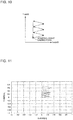
- Fig. 10 is a schematic diagram for explaining movement of the acceleration sensor 20 in the case of acquiring the position information.
- Fig. 11 is a graph for explaining an acquisition result of the position information in a case of the acceleration sensor 20 being moved.
- a graph shown by a solid line shows a position of the acceleration sensor 20 in a case of the position detection process being performed.
- a graph shown by a dotted line shows a position of the acceleration sensor 20 in a case of not performing the position detection process.
- a case where the acceleration sensor 20 is moved on XY coordinates formed of an X-axis and a Y-axis of the three axes is take as an example and explained.
- the position detection device 1 generates the movement acceleration information by removing the static acceleration information from the acceleration information detected by the acceleration sensor 20, and corrects the movement acceleration information by subtracting an error component from the generated movement acceleration information. Subsequently, the position detection device 1 acquires the position information of the apparatus based on the corrected movement acceleration information. Since an error factor at the time of position detection is removed by removing the error component from the acceleration information detected by the acceleration sensor 20, the position information can be detected with high accuracy.
- Embodiment 1 of the present invention is described as above, but the present invention is not limited to embodiment 1 of the present invention described above, and various modifications and applications can be made within the range without departing from the gist of the present invention.
- the starting point and the ending point in the case of moving the acceleration sensor 20 are described as being at the same position, but the starting point and the ending point are not limited to this, and may be different from each other.
- a trend is derived by adding a virtual motion of returning from the ending point to the starting point is added to an end portion of the acceleration information detected by the acceleration sensor 20. Subsequently, the movement acceleration information based on the actual acceleration information detected by the acceleration sensor 20 is corrected with the derived trend.
- position data of the starting point and the ending point become acquirable, and the position data can be used. Specifically, when a position detection device is moved/scanned, movement/scan is started from a determined starting point and movement/scan is completed at a determined ending point. In this way, the position data of the starting point and the ending point that are known in a certain coordinate system can be used by being inputted (can be inputted as set values in advance) to the position detection device and used. Note that there is no problem when the starting point and the ending point are at the same position as a matter of course.
Landscapes
- Engineering & Computer Science (AREA)
- Radar, Positioning & Navigation (AREA)
- Remote Sensing (AREA)
- Automation & Control Theory (AREA)
- Physics & Mathematics (AREA)
- General Physics & Mathematics (AREA)
- Navigation (AREA)
Abstract
Description
- The present invention relates to a position detection device and a position detection method that use an acceleration sensor.
- A method for detecting a position of an apparatus by using an acceleration sensor is conventionally put into practical use. Further, to improve accuracy of position detection using an acceleration sensor, a method in which a global positioning system (GPS) or video information is additionally used is also proposed recently. The method in which position information acquired by a GPS or video information obtained by a camera or the like is combined with the technique of detecting a position by using an acceleration sensor in this way is used in a vehicle-mounted car navigation system, for example.
- On the other hand, there is also proposed a method for detecting a position of an apparatus without using an acceleration sensor. As the method without using an acceleration sensor, there is known a method for correcting position information acquired by a GPS by using image information acquired by a camera, for example (refer to
Non Patent Literature 1, for example). - Further, as the method for detecting a position of an apparatus, a method using a laser transmitter is proposed (refer to
Non Patent Literature 2, for example). In the case of using a laser transmitter, a plurality of laser transmitters are installed around the apparatus, and the position of the apparatus is detected based on information contained in radio waves transmitted and received between the device and the transmitters. -
- Non Patent Literature 1: Agrawal, M., & Konolige, K. (2006). "Real-time Localization in Outdoor Environments using Stereo Vision and Inexpensive GPS." In 18th International Conference on Pattern Recognition (ICPR'06) (pp. 1063-1068). IEEE.
- Non Patent Literature 2: I, M., Wulf,O., & Wagner, B. (2008). "A GPS and Laser-based localization for urban and non-urban outdoor environments." In 2008 IEEE/RSJ International Conference on Intelligent Robots and Systems (pp. 149-154). IEEE.
- However, in the case of using the position information acquired by the GPS as in the method described in
Non Patent Literature 1, the apparatus needs to be able to receive signals by the GPS. Accordingly, in the places where the signals of the GPS cannot be received, such as indoors or mountainous areas, the position cannot be detected. Further, in the case of using the image information acquired by a camera, position detection depends on environmental conditions such as ambient brightness and distance. - Further, in the method described in
Non Patent Literature 2, it is necessary to install laser transmitters around the apparatus. Accordingly, an environment in which the laser transmitters can be installed to detect the position is necessary. Further, since a plurality of laser transmitters are required, cost as the system increases. - In this way, in the conventional position detection method, information obtained from outside is required to enhance accuracy of detection of position of the apparatus by the acceleration sensor, and therefore there is a problem that the environment where the position is detected is limited.
- The present invention is made in the light of the problem in the above described conventional technique, and has an object to provide a position detection device and a position detection method that can enhance accuracy of position detection using an acceleration sensor without using information from outside.
- A position detection device according to an embodiment of the present invention is a position detection device installed in an apparatus, and detecting a position of the apparatus, and includes an acceleration sensor configured to detect acceleration information of the apparatus, a static acceleration removing unit configured to remove static acceleration information indicating acceleration information in a static state of the apparatus, from the acceleration information detected by the acceleration sensor, and generate movement acceleration information indicating acceleration information in a moving state of the apparatus, an error deriving unit configured to derive an error component contained in the movement acceleration information, an acceleration correcting unit configured to correct the movement acceleration information by subtracting the error component from the movement acceleration information, and a position information acquiring unit configured to acquire position information of the apparatus based on the corrected movement acceleration information.
- Further, a position detection method according to an embodiment of the present invention is a position detection method detecting a position of an apparatus, and includes a step of detecting acceleration information of the apparatus, a step of removing static acceleration information indicating acceleration information in a static state of the apparatus, from the detected acceleration information, and generating movement acceleration information indicating acceleration information in a moving state of the apparatus, a step of deriving an error component contained in the movement acceleration information, a step of correcting the movement acceleration information by subtracting the error component from the movement acceleration information, and a step of acquiring position information of the apparatus, based on the corrected movement acceleration information.
- According to an embodiment of the present invention, position information is acquired based on the acceleration information obtained by removing the error component from the acceleration information detected by the acceleration sensor, and thereby accuracy of position detection using the acceleration sensor can be enhanced without using information from outside.
-
- [
Fig. 1] Fig. 1 shows a block diagram showing an example of a configuration of a position detection device according toembodiment 1. - [
Fig. 2] Fig. 2 is a functional block diagram showing an example of a configuration of an arithmetic device inFig. 1 . - [
Fig. 3] Fig. 3 is a flowchart showing an example of a flow of a position detection process by the position detection device inFig. 1 . - [
Fig. 4] Fig. 4 is a graph showing an example of acceleration information detected by an acceleration sensor. - [
Fig. 5] Fig. 5 is a graph showing an example of a result of removing static acceleration information from the acceleration information inFig. 4 . - [
Fig. 6] Fig. 6 is a graph showing an example of a result that a trend is removed from movement acceleration information. - [
Fig. 7] Fig. 7 is a graph showing an example of acceleration information detected by the acceleration sensor. - [
Fig. 8] Fig. 8 is a graph showing an example of velocity information obtained based on the acceleration information inFig. 7 . - [
Fig. 9] Fig. 9 is a graph showing an example of position information obtained based on the velocity information inFig. 8 . - [
Fig. 10] Fig. 10 is a schematic diagram for explaining movement of the acceleration sensor in a case of acquiring position information. - [
Fig. 11] Fig. 11 is a graph for explaining a result of acquisition of position information in a case of the acceleration sensor being moved. - A position detection device according to
embodiment 1 of the present invention will be described hereinafter. The position detection device according toembodiment 1 is used, for example, in a locator or the like for locating objects buried in the ground, and detects a position of an installation apparatus. The position detection device like this is used as an inertial navigation system that detects a position of the installation apparatus without using information obtained from outside, for example. -
Fig. 1 is a block diagram showing an example of a configuration of aposition detection device 1 according to thepresent embodiment 1. As illustrated inFig. 1 , theposition detection device 1 includes anarithmetic device 10 and anacceleration sensor 20, and is installed in an installation apparatus such as a locator. - The
acceleration sensor 20 detects acceleration information in each of three axial directions orthogonal to one another at a preset timing, and supplies the acceleration information to thearithmetic device 10. As theacceleration sensor 20, for example, a micro electro mechanical systems (MEMS) sensor is used. - The
arithmetic device 10 detects a position of the installation apparatus in which theposition detection device 1 is installed, based on acceleration information received from theacceleration sensor 20, and generates position information indicating the position. Thearithmetic device 10 is a microcomputer, for example, and is configured by hardware such as a read only memory (ROM), a random access memory (RAM), a nonvolatile memory, an input device, an output device and a storage device such as a hard disk drive (HDD), and program software executed on a microcomputer, and the like. - In the example, the
arithmetic device 10 and theacceleration sensor 20 are described to be integrally configured as theposition detection device 1, but theposition detection device 1 is not limited to the example. For example, only theacceleration sensor 20 is provided in the installation apparatus, and thearithmetic device 10 may be provided in an external apparatus such as a PC. In this case, thearithmetic device 10 and theacceleration sensor 2 are connected by wire or wirelessly. -
Fig. 2 is a functional block diagram showing an example of a configuration of thearithmetic device 10 inFig. 1 . As shown inFig. 2 , thearithmetic device 10 includes a staticacceleration removing unit 11, anerror deriving unit 12, anacceleration correcting unit 13 and a positioninformation acquiring unit 14. - The static
acceleration removing unit 11 performs processing of removing acceleration information in a static state before and after movement of the installation apparatus, from acceleration information supplied from theacceleration sensor 20. Specifically, the staticacceleration removing unit 11 removes static acceleration information that is acceleration information in a static state before the installation apparatus starts movement, and a static state after end of the movement. Subsequently, the staticacceleration removing unit 11 extracts movement acceleration information that is acceleration information in a moving state of the installation apparatus. - The
error deriving unit 12 derives a trend that is an error component contained in the acceleration information, based on the movement acceleration information extracted in the staticacceleration removing unit 11. The trend is an error component such as a direct current (DC) offset component caused by hysteresis that is a characteristic of the MEMS sensor when the MEMS sensor is used as theacceleration sensor 20, for example. - The
acceleration correcting unit 13 performs processing of correcting the movement acceleration information based on the movement acceleration information extracted in the staticacceleration removing unit 11, and the trend derived in theerror deriving unit 12. Specifically, theacceleration correcting unit 13 subtracts the trend from the movement acceleration information, and thereby corrects the movement acceleration information. - The position
information acquiring unit 14 acquires position information indicating a position from a starting point of theacceleration sensor 20 provided in the installation apparatus, based on the movement acceleration information corrected in theacceleration correcting unit 13. Specifically, the positioninformation acquiring unit 14 performs integration two times on the corrected movement acceleration information, and thereby acquires position information. At this time, the positioninformation acquiring unit 14 uses position information on the starting point and an ending point of theacceleration sensor 20 that are set in advance. - Next, a position detection process will be described. In the
present embodiment 1, position information with high accuracy is acquired by removing an error component contained in the acceleration information, when the position information is acquired from the acceleration information detected by theacceleration sensor 20. -
Fig. 3 is a flowchart showing an example of a flow of the position detection process by theposition detection device 1 inFig. 1 . In the following, a case of detecting a position in any one axial direction of the three axial directions detected by theacceleration sensor 20 will be described by being taken as an example. As for a case of detecting positions of the other two axial directions, the positions can be detected by performing a same process. - First, a user who performs position detection moves the installation apparatus in which the
acceleration sensor 20 is provided manually or automatically (step S1). In this case, the user disposes the installation apparatus in which theacceleration sensor 20 is provided in a position to be a starting point of position detection, and thereafter moves the installation apparatus so that the starting point becomes an ending point. At this time, theacceleration sensor 20 detects acceleration information at a set timing, and supplies the detected acceleration information to the staticacceleration removing unit 11 of the arithmetic device 10 (step S2). In the following explanation, "moving the installation equipment in which theacceleration sensor 20 is provided" will be described simply as "moving theacceleration sensor 20". - Next, the static
acceleration removing unit 11 removes static acceleration information that is acceleration information in a static state before and after movement from the acceleration information detected by the acceleration sensor 20 (step S3). - The acceleration information detected by the
acceleration sensor 20 may also contain acceleration information in the static state before start of movement of theacceleration sensor 20 and after end of the movement. - In general, when the
acceleration sensor 20 of MEMS is used, acceleration does not become "0" even when theacceleration sensor 20 is in a static state, and may indicate a value as if theacceleration sensor 20 is moving. The value of the acceleration in the static state becomes an error at a time of detecting a position, and becomes a cause of reducing detection accuracy. Therefore, in step S3, processing of removing the static acceleration information that is the acceleration information in the static state, from the acceleration information detected in theacceleration sensor 20 is performed. - Determination of whether the
acceleration sensor 20 is in a static state, or in a moving state is performed based on jerk in the acceleration information detected by the sensor. Jerk indicates a change amount of the acceleration per unit time. When the state transitions from a static state to a moving state, or from the moving state to the static state, for example, the acceleration changes greatly, and therefore the jerk has a large value. - Accordingly, a range to be a threshold is set in advance to the jerk, and when the jerk is within a set range of the threshold, the
acceleration sensor 20 can be determined as moving or stopping. In this way, the staticacceleration removing unit 11 removes the static acceleration information from the acceleration information detected by theacceleration sensor 20, and generates movement acceleration information that is the acceleration information in the moving state. - Next, the
error deriving unit 12 of thearithmetic device 10 performs processing of deriving a trend that is an error component contained in the acceleration information from the movement acceleration information (step S4). Subsequently, theacceleration correcting unit 13 of thearithmetic device 10 performs correction processing of the movement acceleration information based on the trend derived in the error deriving unit 12 (step S5). - The movement acceleration information generated by the static
acceleration removing unit 11 based on the acceleration information detected by theacceleration sensor 20 contains a trend that is an error component such as a DC offset to the acceleration caused by hysteresis as the characteristic of the MEMS sensor. Accordingly, an influence by the trend needs to be removed to detect the position of theacceleration sensor 20 accurately. - When the movement acceleration information based on the detection result of the
acceleration sensor 20 is set as f(t), the error component (trend) is set as ε(t), and true acceleration information is set as α(t), a relationship shown in expression (1) is established among them.
[Expression 1]
- The trend contains a direct-current component such as a DC offset, and a component changing gradually over time. Accordingly, the trend ε(t) is defined by an approximate expression by a linear function or the like as in expression (2) here. Here, "a" and "b" in expression (2) are constants for determining the trend ε(t).
[Expression 2]
- Accordingly, based on expression (1) and expression (2), the movement acceleration information f(t) can be expressed as shown in expression (3).
[Expression 3]
- Next, an error function Error to the movement acceleration information f(t) in a case where acceleration being measured by the
acceleration sensor 20 from atime 0 to time T is defined as shown in expression (4).
[Expression 4]
- Subsequently, the constants a and b that make the value of the error function Error in expression (4) minimum are calculated. This corresponds to approximating the movement acceleration information f(t) by a least square using a linear function of "at+b". Thereby, the trend ε(t) is determined. Approximation is not limited to the approximation as described above, but a known approximation method such as a method using an n-order function that is a quadratic function or more can be used.
- Next, expression (5) to calculate the true acceleration information α(t) is derived from expression (3), and the true acceleration information α(t) that is a result of removing the trend ε(t) from the movement acceleration information f(t) can be obtained by using the constants a and b calculated based on expression (4).
[Expression 5]
- Next, the position
information acquiring unit 14 of thearithmetic device 10 performs processing of acquiring position information based on the true acceleration information α(t) calculated in the acceleration correcting unit 13 (step S6). The position information can be calculated by performing integration two times on the true acceleration information α(t). - First, the position
information acquiring unit 14 calculates velocity information v(t) based on the calculated true acceleration information α(t). The velocity information v(t) can be obtained by integrating the true acceleration information α(t), and is calculated by expression (6). In expression (6), velocity information v(0) is an initial value, and indicates a velocity before start of measurement of the acceleration.
[Expression 6]
- Further, velocity information v(T) at a time T when measurement of the acceleration by the
acceleration sensor 20 is ended is calculated based on expression (7). The velocity information v(0) in expression (7) indicates a velocity before start of measurement of the acceleration as in expression (6).
[Expression 7]
- Here, since the
acceleration sensor 20 is in a static state before start and after end of measurement of the acceleration in thepresent embodiment 1, the velocity information v(0) in expression (6) and expression (7), and the velocity information v(T) in expression (7) have values of "0". This is understandable from the fact that the direct-current component contained in the trend ε(t) is removed from the movement acceleration information f(t) in expression (5). - Next, the position
information acquiring unit 14 calculates position information x(t) based on the calculated velocity information v(t). The position information x(t) can be obtained by integrating the velocity information v(t), and can be calculated by expression (8). In expression (8), position information x(0) is an initial value, and indicates a position before start of measurement of the acceleration.
[Expression 8]
- Further, position information x(T) at the time T when measurement of the acceleration by the
acceleration sensor 20 is ended is calculated based on expression (9). The position information x(0) in expression (9) indicates a position before start of measurement of the acceleration as in expression (8).
[Expression 9]
- Note that the direct-current component and the trend component contained in the velocity information v(t) are already removed as expressed by "v(0)=v(T)=0". Accordingly, a value of the position information x(T) is also "0". In other words, a position before measurement and a position after measurement of the acceleration correspond to each other.
- In this way, in the
present embodiment 1, theacceleration sensor 20 is moved so that the position before measurement of the acceleration and the position after measurement of the acceleration correspond to each other, and the movement acceleration information f(t) at this time is derived. - Subsequently, the position information x(t) is acquired based on the true acceleration information α(t) obtained by removing the trend ε(t) from the derived movement acceleration information f(t). Thereby, various error factors contained in the acceleration information detected by the
acceleration sensor 20 are removed, and therefore the position of theacceleration sensor 20 can be detected with high accuracy. -
Fig. 4 is a graph showing an example of the acceleration information detected by theacceleration sensor 20.Fig. 5 is a graph showing an example of the result that the static acceleration information is removed from the acceleration information inFig. 4 . As shown inFig. 4 and Fig. 5 , it is found that the static acceleration information is removed by the staticacceleration removing unit 11, and thereby the static acceleration information on the states before and after movement is removed. In the states before and after movement, theacceleration sensor 20 is considered to be in a static state. -
Fig. 6 is a graph showing an example of a result that the trend is removed from the movement acceleration information. InFig. 6 , a graph shown by a solid line shows the movement acceleration information f(t) generated by the staticacceleration removing unit 11. A graph shown by a dotted line shows the true acceleration information α(t) obtained by removing the trend from the movement acceleration information f(t) by theacceleration correcting unit 13. A graph shown by a chain line shows the trend ε(t). - As shown in
Fig. 6 , it is found that due to an error component such as a DC offset, the acceleration is not "0" in the movement acceleration information f(t) in the static state before movement and in the static state after movement. In contrast with this, in the true acceleration information α(t) obtained by removing the trend, the acceleration is "0" in the static state before movement and in the static state after movement, and it is found that the static states are correctly detected. -
Fig. 7 is a graph showing an example of the acceleration information detected by theacceleration sensor 20.Fig. 8 is a graph showing an example of the velocity information obtained based on the acceleration information inFig. 7. Fig. 9 is a graph showing an example of the position information obtained based on the velocity information inFig. 8 . -
Fig. 7 shows acceleration information detected by theacceleration sensor 20.Fig. 8 shows velocity information obtained by integrating the acceleration information inFig. 7. Fig. 9 shows position information obtained by integrating the velocity information inFig. 8 . It is found that the position information of theacceleration sensor 20 can be acquired by performing integration two times on the acceleration information detected by theacceleration sensor 20 in this way. - Next, a detection result of the position information in a case of the position detection process shown in
Fig. 3 being performed will be described. Here, theacceleration sensor 20 is actually moved, and a case where the position information is acquired by performing the position detection process shown inFig. 3 , and a case where the position information is acquired without performing the position detection process are compared and explained. -
Fig. 10 is a schematic diagram for explaining movement of theacceleration sensor 20 in the case of acquiring the position information.Fig. 11 is a graph for explaining an acquisition result of the position information in a case of theacceleration sensor 20 being moved. InFig. 11 , a graph shown by a solid line shows a position of theacceleration sensor 20 in a case of the position detection process being performed. A graph shown by a dotted line shows a position of theacceleration sensor 20 in a case of not performing the position detection process. Here, a case where theacceleration sensor 20 is moved on XY coordinates formed of an X-axis and a Y-axis of the three axes is take as an example and explained. - When the
acceleration sensor 20 is moved from a set starting point to an ending point at a same position as the starting point in an order indicated by arrows inFig. 10 , it is found that a position detection result substantially equivalent to a locus at a time of theacceleration sensor 20 being actually moved is obtained when the position detection process is performed as shown inFig. 11 . In contrast with this, when the position detection process is not performed, the position detection result different from a moving locus of theacceleration sensor 20 is obtained. In particular, in the example, it is found that the position of the starting point and the position of the ending point do not correspond to each other. - As above, the
position detection device 1 according to thepresent embodiment 1 generates the movement acceleration information by removing the static acceleration information from the acceleration information detected by theacceleration sensor 20, and corrects the movement acceleration information by subtracting an error component from the generated movement acceleration information. Subsequently, theposition detection device 1 acquires the position information of the apparatus based on the corrected movement acceleration information. Since an error factor at the time of position detection is removed by removing the error component from the acceleration information detected by theacceleration sensor 20, the position information can be detected with high accuracy. -
Embodiment 1 of the present invention is described as above, but the present invention is not limited toembodiment 1 of the present invention described above, and various modifications and applications can be made within the range without departing from the gist of the present invention. - For example, in the aforementioned example, the starting point and the ending point in the case of moving the
acceleration sensor 20 are described as being at the same position, but the starting point and the ending point are not limited to this, and may be different from each other. In this case, a trend is derived by adding a virtual motion of returning from the ending point to the starting point is added to an end portion of the acceleration information detected by theacceleration sensor 20. Subsequently, the movement acceleration information based on the actual acceleration information detected by theacceleration sensor 20 is corrected with the derived trend. - Further, by using a starting point and an ending point of which positions are known in a certain coordinate system, position data of the starting point and the ending point become acquirable, and the position data can be used. Specifically, when a position detection device is moved/scanned, movement/scan is started from a determined starting point and movement/scan is completed at a determined ending point. In this way, the position data of the starting point and the ending point that are known in a certain coordinate system can be used by being inputted (can be inputted as set values in advance) to the position detection device and used. Note that there is no problem when the starting point and the ending point are at the same position as a matter of course.
-
- 1
- position detection device
- 10
- arithmetic device
- 11
- static acceleration removing unit
- 12
- error deriving unit
- 13
- acceleration correcting unit
- 14
- position information acquiring unit
- 20
- acceleration sensor
Claims (7)
- A position detection device installed in an apparatus, and detecting a position of the apparatus, the position detection device comprising:an acceleration sensor configured to detect acceleration information of the apparatus;a static acceleration removing unit configured to remove static acceleration information indicating acceleration information in a static state of the apparatus, from the acceleration information detected by the acceleration sensor, and generate movement acceleration information indicating acceleration information in a moving state of the apparatus;an error deriving unit configured to derive an error component contained in the movement acceleration information;an acceleration correcting unit configured to correct the movement acceleration information by subtracting the error component from the movement acceleration information; anda position information acquiring unit configured to acquire position information of the apparatus based on the corrected movement acceleration information.
- The position detection device of claim 1, wherein the position information acquiring unit detects a position by using data of a starting point position of the apparatus and data of an ending point position at a time of the apparatus being moved when detecting the position of the apparatus, based on the acceleration information detected by the acceleration sensor.
- The position detection device of claim 1 or 2, wherein
the error deriving unit
derives the error component by an approximate expression. - The position detection device of claim 3, wherein
the approximate expression is an approximate expression by a linear function. - The position detection device of any one of claims 1 to 4, wherein
the static acceleration removing unit
compares a jerk indicating a change amount of the acceleration information and a set range, and determines that acceleration information corresponding to the jerk is the static acceleration information when the jerk is within the set range. - The position detection device of any one of claims 1 to 5, wherein
the position information acquiring unit
acquires the position information by performing integration two times on the corrected movement acceleration information. - A position detection method detecting a position of an apparatus, the method comprising:a step of detecting acceleration information of the apparatus;a step of removing static acceleration information indicating acceleration information in a static state of the apparatus, from the detected acceleration information, and generating movement acceleration information indicating acceleration information in a moving state of the apparatus;a step of deriving an error component contained in the movement acceleration information;a step of correcting the movement acceleration information by subtracting the error component from the movement acceleration information; anda step of acquiring position information of the apparatus, based on the corrected movement acceleration information.
Applications Claiming Priority (2)
| Application Number | Priority Date | Filing Date | Title |
|---|---|---|---|
| JP2017116337A JP6967766B2 (en) | 2017-06-13 | 2017-06-13 | Position detection device and position detection method |
| PCT/JP2018/022425 WO2018230560A1 (en) | 2017-06-13 | 2018-06-12 | Position detecting device and position detecting method |
Publications (2)
| Publication Number | Publication Date |
|---|---|
| EP3640593A1 true EP3640593A1 (en) | 2020-04-22 |
| EP3640593A4 EP3640593A4 (en) | 2021-03-10 |
Family
ID=64660165
Family Applications (1)
| Application Number | Title | Priority Date | Filing Date |
|---|---|---|---|
| EP18818319.8A Withdrawn EP3640593A4 (en) | 2017-06-13 | 2018-06-12 | POSITION DETECTION DEVICE AND POSITION DETECTION METHOD |
Country Status (4)
| Country | Link |
|---|---|
| US (1) | US20200191573A1 (en) |
| EP (1) | EP3640593A4 (en) |
| JP (1) | JP6967766B2 (en) |
| WO (1) | WO2018230560A1 (en) |
Families Citing this family (1)
| Publication number | Priority date | Publication date | Assignee | Title |
|---|---|---|---|---|
| JP7506313B2 (en) * | 2020-09-03 | 2024-06-26 | 日本製鉄株式会社 | Processing device, processing method, and program |
Family Cites Families (6)
| Publication number | Priority date | Publication date | Assignee | Title |
|---|---|---|---|---|
| JPH109877A (en) * | 1996-06-21 | 1998-01-16 | Omron Corp | Vehicle speed detection system and navigation device using the same |
| JP2006250947A (en) * | 2006-04-28 | 2006-09-21 | Toyota Motor Corp | Output correction device for vehicle acceleration sensor |
| JP2009025012A (en) * | 2007-07-17 | 2009-02-05 | Alpine Electronics Inc | Acceleration sensor offset correction apparatus and method |
| US8694224B2 (en) * | 2012-03-01 | 2014-04-08 | Magna Electronics Inc. | Vehicle yaw rate correction |
| DE102012222893A1 (en) * | 2012-12-12 | 2014-06-12 | Robert Bosch Gmbh | Method for determining the offset value of a sensor signal |
| US9121866B2 (en) * | 2013-03-15 | 2015-09-01 | Autoliv Asp, Inc. | System and method for inertial sensor offset compensation |
-
2017
- 2017-06-13 JP JP2017116337A patent/JP6967766B2/en active Active
-
2018
- 2018-06-12 US US16/621,952 patent/US20200191573A1/en not_active Abandoned
- 2018-06-12 WO PCT/JP2018/022425 patent/WO2018230560A1/en not_active Ceased
- 2018-06-12 EP EP18818319.8A patent/EP3640593A4/en not_active Withdrawn
Also Published As
| Publication number | Publication date |
|---|---|
| JP2019002749A (en) | 2019-01-10 |
| JP6967766B2 (en) | 2021-11-17 |
| EP3640593A4 (en) | 2021-03-10 |
| US20200191573A1 (en) | 2020-06-18 |
| WO2018230560A1 (en) | 2018-12-20 |
Similar Documents
| Publication | Publication Date | Title |
|---|---|---|
| EP3674747B1 (en) | Signal processing device, signal processing method, program, moving body, and signal processing system | |
| US9275458B2 (en) | Apparatus and method for providing vehicle camera calibration | |
| US10436884B2 (en) | Calibration of laser and vision sensors | |
| EP3663882B1 (en) | Information processing device, information processing method, program and mobile unit | |
| US9330343B2 (en) | Image analysis apparatus mounted to vehicle | |
| CN109099920B (en) | Sensor target accurate positioning method based on multi-sensor association | |
| US10353072B2 (en) | Laser scanner controlling device, laser scanner controlling method, and laser scanner controlling program | |
| US10269127B2 (en) | Object detecting method and object detecting device | |
| EP2637149A1 (en) | Onboard device and control method | |
| EP3955209A1 (en) | Machine learning and vision-based approach to zero velocity update object detection | |
| KR20130134916A (en) | Apparatus and method for detecting moving-object of surrounding of vehicle | |
| KR102428765B1 (en) | Autonomous driving vehicle navigation system using the tunnel lighting | |
| KR20200052751A (en) | Apparatus and method for detecting position of vehicle and vehicle including the same | |
| US12228652B2 (en) | Apparatus for estimating vehicle pose using lidar sensor and method thereof | |
| CN112823321B (en) | Position positioning system and method for mixing position recognition results based on multiple types of sensors | |
| KR102103651B1 (en) | Method for reduction of particle filtering degeneracy exploiting lane number from digital map and system using the method | |
| CN110658542B (en) | Method, device, equipment and storage medium for positioning and identifying automatic driving automobile | |
| EP3640593A1 (en) | Position detecting device and position detecting method | |
| EP1307705B1 (en) | Height measurement apparatus | |
| US11754403B2 (en) | Self-position correction method and self-position correction device | |
| JPH1139464A (en) | Vehicle image processing device | |
| KR101376536B1 (en) | Position Recognition Method for mobile object using convergence of sensors and Apparatus thereof | |
| KR101207462B1 (en) | System for sensor revision used image information and distant-angle information | |
| US10830906B2 (en) | Method of adaptive weighting adjustment positioning | |
| CN113899339B (en) | Distance detection method and device and vehicle |
Legal Events
| Date | Code | Title | Description |
|---|---|---|---|
| STAA | Information on the status of an ep patent application or granted ep patent |
Free format text: STATUS: THE INTERNATIONAL PUBLICATION HAS BEEN MADE |
|
| PUAI | Public reference made under article 153(3) epc to a published international application that has entered the european phase |
Free format text: ORIGINAL CODE: 0009012 |
|
| STAA | Information on the status of an ep patent application or granted ep patent |
Free format text: STATUS: REQUEST FOR EXAMINATION WAS MADE |
|
| 17P | Request for examination filed |
Effective date: 20191218 |
|
| AK | Designated contracting states |
Kind code of ref document: A1 Designated state(s): AL AT BE BG CH CY CZ DE DK EE ES FI FR GB GR HR HU IE IS IT LI LT LU LV MC MK MT NL NO PL PT RO RS SE SI SK SM TR |
|
| AX | Request for extension of the european patent |
Extension state: BA ME |
|
| DAV | Request for validation of the european patent (deleted) | ||
| DAX | Request for extension of the european patent (deleted) | ||
| A4 | Supplementary search report drawn up and despatched |
Effective date: 20210208 |
|
| RIC1 | Information provided on ipc code assigned before grant |
Ipc: G01P 21/00 20060101ALI20210202BHEP Ipc: G01C 21/16 20060101AFI20210202BHEP |
|
| STAA | Information on the status of an ep patent application or granted ep patent |
Free format text: STATUS: THE APPLICATION HAS BEEN WITHDRAWN |
|
| 18W | Application withdrawn |
Effective date: 20210816 |