EP3640549B1 - Air conditioner system and air conditioner having same - Google Patents
Air conditioner system and air conditioner having same Download PDFInfo
- Publication number
- EP3640549B1 EP3640549B1 EP18892332.0A EP18892332A EP3640549B1 EP 3640549 B1 EP3640549 B1 EP 3640549B1 EP 18892332 A EP18892332 A EP 18892332A EP 3640549 B1 EP3640549 B1 EP 3640549B1
- Authority
- EP
- European Patent Office
- Prior art keywords
- pipeline
- liquid separator
- cylinder
- communication
- air
- Prior art date
- Legal status (The legal status is an assumption and is not a legal conclusion. Google has not performed a legal analysis and makes no representation as to the accuracy of the status listed.)
- Active
Links
Images


Classifications
-
- F—MECHANICAL ENGINEERING; LIGHTING; HEATING; WEAPONS; BLASTING
- F25—REFRIGERATION OR COOLING; COMBINED HEATING AND REFRIGERATION SYSTEMS; HEAT PUMP SYSTEMS; MANUFACTURE OR STORAGE OF ICE; LIQUEFACTION SOLIDIFICATION OF GASES
- F25B—REFRIGERATION MACHINES, PLANTS OR SYSTEMS; COMBINED HEATING AND REFRIGERATION SYSTEMS; HEAT PUMP SYSTEMS
- F25B7/00—Compression machines, plants or systems, with cascade operation, i.e. with two or more circuits, the heat from the condenser of one circuit being absorbed by the evaporator of the next circuit
-
- F—MECHANICAL ENGINEERING; LIGHTING; HEATING; WEAPONS; BLASTING
- F25—REFRIGERATION OR COOLING; COMBINED HEATING AND REFRIGERATION SYSTEMS; HEAT PUMP SYSTEMS; MANUFACTURE OR STORAGE OF ICE; LIQUEFACTION SOLIDIFICATION OF GASES
- F25B—REFRIGERATION MACHINES, PLANTS OR SYSTEMS; COMBINED HEATING AND REFRIGERATION SYSTEMS; HEAT PUMP SYSTEMS
- F25B41/00—Fluid-circulation arrangements
- F25B41/20—Disposition of valves, e.g. of on-off valves or flow control valves
-
- F—MECHANICAL ENGINEERING; LIGHTING; HEATING; WEAPONS; BLASTING
- F24—HEATING; RANGES; VENTILATING
- F24F—AIR-CONDITIONING; AIR-HUMIDIFICATION; VENTILATION; USE OF AIR CURRENTS FOR SCREENING
- F24F1/00—Room units for air-conditioning, e.g. separate or self-contained units or units receiving primary air from a central station
- F24F1/0007—Indoor units, e.g. fan coil units
- F24F1/0059—Indoor units, e.g. fan coil units characterised by heat exchangers
-
- F—MECHANICAL ENGINEERING; LIGHTING; HEATING; WEAPONS; BLASTING
- F25—REFRIGERATION OR COOLING; COMBINED HEATING AND REFRIGERATION SYSTEMS; HEAT PUMP SYSTEMS; MANUFACTURE OR STORAGE OF ICE; LIQUEFACTION SOLIDIFICATION OF GASES
- F25B—REFRIGERATION MACHINES, PLANTS OR SYSTEMS; COMBINED HEATING AND REFRIGERATION SYSTEMS; HEAT PUMP SYSTEMS
- F25B1/00—Compression machines, plants or systems with non-reversible cycle
- F25B1/10—Compression machines, plants or systems with non-reversible cycle with multi-stage compression
-
- F—MECHANICAL ENGINEERING; LIGHTING; HEATING; WEAPONS; BLASTING
- F25—REFRIGERATION OR COOLING; COMBINED HEATING AND REFRIGERATION SYSTEMS; HEAT PUMP SYSTEMS; MANUFACTURE OR STORAGE OF ICE; LIQUEFACTION SOLIDIFICATION OF GASES
- F25B—REFRIGERATION MACHINES, PLANTS OR SYSTEMS; COMBINED HEATING AND REFRIGERATION SYSTEMS; HEAT PUMP SYSTEMS
- F25B13/00—Compression machines, plants or systems, with reversible cycle
-
- F—MECHANICAL ENGINEERING; LIGHTING; HEATING; WEAPONS; BLASTING
- F25—REFRIGERATION OR COOLING; COMBINED HEATING AND REFRIGERATION SYSTEMS; HEAT PUMP SYSTEMS; MANUFACTURE OR STORAGE OF ICE; LIQUEFACTION SOLIDIFICATION OF GASES
- F25B—REFRIGERATION MACHINES, PLANTS OR SYSTEMS; COMBINED HEATING AND REFRIGERATION SYSTEMS; HEAT PUMP SYSTEMS
- F25B41/00—Fluid-circulation arrangements
- F25B41/30—Expansion means; Dispositions thereof
-
- F—MECHANICAL ENGINEERING; LIGHTING; HEATING; WEAPONS; BLASTING
- F04—POSITIVE - DISPLACEMENT MACHINES FOR LIQUIDS; PUMPS FOR LIQUIDS OR ELASTIC FLUIDS
- F04C—ROTARY-PISTON, OR OSCILLATING-PISTON, POSITIVE-DISPLACEMENT MACHINES FOR LIQUIDS; ROTARY-PISTON, OR OSCILLATING-PISTON, POSITIVE-DISPLACEMENT PUMPS
- F04C18/00—Rotary-piston pumps specially adapted for elastic fluids
- F04C18/30—Rotary-piston pumps specially adapted for elastic fluids having the characteristics covered by two or more of groups F04C18/02, F04C18/08, F04C18/22, F04C18/24, F04C18/48, or having the characteristics covered by one of these groups together with some other type of movement between co-operating members
- F04C18/34—Rotary-piston pumps specially adapted for elastic fluids having the characteristics covered by two or more of groups F04C18/02, F04C18/08, F04C18/22, F04C18/24, F04C18/48, or having the characteristics covered by one of these groups together with some other type of movement between co-operating members having the movement defined in group F04C18/08 or F04C18/22 and relative reciprocation between the co-operating members
- F04C18/356—Rotary-piston pumps specially adapted for elastic fluids having the characteristics covered by two or more of groups F04C18/02, F04C18/08, F04C18/22, F04C18/24, F04C18/48, or having the characteristics covered by one of these groups together with some other type of movement between co-operating members having the movement defined in group F04C18/08 or F04C18/22 and relative reciprocation between the co-operating members with vanes reciprocating with respect to the outer member
Definitions
- the lowest evaporating temperature obtained by the double-stage compression refrigeration device employing medium-temperature refrigerant is also limited by a series of problems caused by too low evaporation pressure.
- the pressure difference between the evaporator pressure and the outside pressure increases, the possibility that the air infiltrates into the system increases, which will affect the normal operation of the system.
- the suction specific volume is large, and the gas actually sucked into the cylinder is reduced, which causes an increase of the size of the cylinder. Therefore, when a low evaporation temperature is required, a low-temperature refrigerant should be used.
- the first pipeline and the second pipeline are provided independently; the first pipeline and the second pipeline are respectively in communication with the same one compressor; and the first liquid separator and the second liquid separator are arranged in the first pipeline respectively.
- the air-conditioning system can realize a cascade refrigeration cycle. Since only one compressor is employed in the system, the cost of manufacturing the air-conditioning system is effectively saved.
- the upper cylinder and the lower cylinder of the twin cylinder compressor independently complete the compression processes of the two refrigeration circulations respectively, and the compressor with one unit and double refrigerants simplifies the cascaded circulation system.
- the two cylinders need to be connected to the liquid separator component separately.
- the first cylinder is a high-temperature refrigerant cylinder. After flowing through the first liquid separator and entering the first cylinder, the high-temperature refrigerant is compressed, and then discharged into an intermediate cavity of the upper flange, and finally discharged out of the high-temperature refrigerant discharge pipe 2.
- the second cylinder is a low-temperature refrigerant cylinder.
- the evaporative condenser When operating in the system with double refrigerants, the evaporative condenser acts as an evaporator of the high-temperature refrigerant; after flowing through the first liquid separator and entering the high-temperature refrigerant cylinder, the high-temperature refrigerant at a low-temperature and low-pressure state is compressed and discharged into the inner cavity of the lower flange, then is discharged from the high-temperature discharge pipe into the condenser and then the throttle valve, and finally flows back to the evaporative condenser, thereby completing a circulation cycle of the high-temperature refrigerant. After the high-temperature refrigerant circulates for a period of time, the low-temperature refrigerant begins to circulate.
- the refrigerant After the low-temperature refrigerant from the evaporator flows through the second liquid separator and enters the low-temperature refrigerant cylinder, the refrigerant is compressed and discharged from the discharge port of the upper flange into the inner cavity of the compressor.
- the effective volume ratio of the first liquid separator to the second liquid separator ranges from 2.5 to 6.0.
- the discharge temperature of the low-temperature refrigerant is lower, which takes an effect on lowering the temperature of the compressor motor.
- the low-temperature refrigerant flows through the low-temperature refrigerant discharge pipe and enters the evaporative condenser, then enter the throttle valve, and finally flows back to the evaporator, thereby completing a circulation cycle of the low-temperature refrigerant.
- a second liquid separator is provided independently at the suction inlet of the low-temperature refrigerant cylinder.
- the inner cavity of the lower flange is used as a high-temperature refrigerant discharge cavity.
- a high-temperature refrigerant discharge port is independently disposed in the lower flange and is in communication with the high-temperature refrigerant discharge pipe. The sealing distances between the parts inside the pump body are ensured to be sufficient, and the first cylinder and the second cylinder can be independently compressed.
- FIG.3 is a top view of the compressor with one unit and double refrigerants. As far as the appearance is concerned, the compressor is provided with two liquid separators with different specifications corresponding to the high-temperature refrigerant discharge pipe and the low-temperature refrigerant discharge pipe. The low-temperature refrigerant is discharged into the housing of the compressor first, which takes an effect on lowering the temperature of the compressor motor.
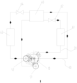
- FIG.1 is a principle diagram of the system using the compressor with one unit and double refrigerants.
- two independent refrigeration circulations are related through the evaporative condenser, and also through the compressor with double refrigerants; the evaporative condenser acts as an evaporator of the high-temperature refrigerant; after flowing through the first liquid separator and entering the high-temperature refrigerant cylinder, the high-temperature refrigerant at the low-temperature and low-pressure state is compressed and discharged into the inner cavity of the lower flange, then is discharged from the high-temperature discharge pipe into the condenser and the throttle valve, and finally flows back to the evaporative condenser, thereby completing a circulation cycle of the high-temperature refrigerant.
- the low-temperature refrigerant After the high-temperature refrigerant circulates for a period of time, the low-temperature refrigerant begins to circulate. After the low-temperature refrigerant from the evaporator flows through the second liquid separator and enters the low-temperature refrigerant cylinder, the refrigerant is compressed, and discharged from the discharge port of the upper flange into the inner cavity of the compressor. The discharge temperature of the low-temperature refrigerant is lower, which takes an effect on lowering the temperature of the compressor motor.
- the low-temperature refrigerant flows through the low-temperature refrigerant discharge pipe, and enters the evaporative condenser and the throttle valve, and finally flows back to the evaporator, thereby completing a circulation cycle of the low-temperature refrigerant.
Landscapes
- Engineering & Computer Science (AREA)
- Physics & Mathematics (AREA)
- Thermal Sciences (AREA)
- Mechanical Engineering (AREA)
- General Engineering & Computer Science (AREA)
- Chemical & Material Sciences (AREA)
- Combustion & Propulsion (AREA)
- Compressors, Vaccum Pumps And Other Relevant Systems (AREA)
- Applications Or Details Of Rotary Compressors (AREA)
- Compression-Type Refrigeration Machines With Reversible Cycles (AREA)
- Air-Conditioning For Vehicles (AREA)
Description
- The present invention relates to the technical field of air-conditioning equipment, and in particular, to an air-conditioning system and an air conditioner having the same.
- As the requirements of scientific research and production for low temperature are becoming higher, the lowest evaporating temperature obtained by the double-stage compression refrigeration device employing medium-temperature refrigerant is also limited by a series of problems caused by too low evaporation pressure. For example, when the pressure difference between the evaporator pressure and the outside pressure increases, the possibility that the air infiltrates into the system increases, which will affect the normal operation of the system. The suction specific volume is large, and the gas actually sucked into the cylinder is reduced, which causes an increase of the size of the cylinder. Therefore, when a low evaporation temperature is required, a low-temperature refrigerant should be used. However, the condensation temperature of the low-temperature refrigerant is required to be lower, and the refrigerant cannot be condensed into liquid by ordinary water cooling and air cooling. A kind of artificial cold source is required to condense the low-temperature refrigerant, accordingly, a cascaded refrigeration cycle adopting two kinds of refrigerants occurs. However, multiple compressors are employed to realize the cascaded refrigeration cycle in the existing technology, which causes a problem of an increase of the cost of implementing a cascade refrigeration cycle in the existing technology.
-
JP2013181513 (A - The main objective of the present invention is to provide an air-conditioning system and an air conditioner having the same, so as to solve a problem of a high cost of manufacturing the air-conditioning system in the prior art.
- In order to achieve the above objective, according to one aspect of the present invention, an air-conditioning system is provided as set out in claim 1 below.
- Further, the air-conditioning system further includes a condenser; the condenser is arranged in the first pipeline; an inlet of the condenser is in communication with the discharge port of the first cylinder; an outlet of the condenser is in communication with a first inlet of the evaporative condenser; and a first outlet of the evaporative condenser is in communication with the inlet of the first liquid separator.
- Further, the air-conditioning system further includes a first throttle valve; the first throttle valve is arranged in the first pipeline and located between the evaporative condenser and the condenser.
- Further, the air-conditioning system further includes an evaporator; the evaporator is arranged in the second pipeline; an inlet of the evaporator is in communication with a second outlet of the evaporative condenser; and an outlet of the evaporator is in communication with the inlet of the second liquid separator.
- Further, the air-conditioning system further includes a second throttle valve; the second throttle valve is arranged in the second pipeline and is located between the evaporative condenser and the evaporator.
- Further, a height ratio of the second cylinder to the first cylinder is T3, wherein 0.75≤T3≤ 0.95.Further, an effective volume ratio of the first liquid separator to the second liquid separator is T4, wherein 2.5≤T4≤6.
- According to another aspect of the present invention, the present invention provides an air conditioner including the air-conditioning system above.
- In the technical solution of the air-conditioning system of the present disclosure, the first pipeline and the second pipeline are provided independently; the first pipeline and the second pipeline are respectively in communication with the same one compressor; and a first liquid separator and a second liquid separator are arranged in the first pipeline respectively. The air-conditioning system can realize a cascade refrigeration cycle. Since only one compressor is employed in the system, the cost of manufacturing the air-conditioning system is effectively saved.
- The accompanying drawings attached to the specification form a part of the disclosure and are intended to provide a further understanding of the present disclosure. The illustrative embodiments of the present disclosure and the description thereof are used for explanations of the present disclosure, but not intended to limit the present disclosure improperly. In the accompanying drawings:
-
FIG. 1 is a structural schematic diagram illustrating an air-conditioning system according to an embodiment of the present invention; -
FIG. 2 is a structural schematic diagram of a compressor according to a first embodiment of the present invention; -
FIG. 3 is a schematic structural diagram of a compressor according to a second embodiment of the present invention. - Wherein, the drawings include following reference signs:
- 1. low-temperature discharge pipe; 2. high-temperature discharge pipe;
- 10. compressor; 11. first cylinder; 12. second cylinder;
- 20. first pipeline; 30. second pipeline; 40. evaporative condenser; 51. first liquid separator; 52. second liquid separator; 61. condenser; 62. first throttle valve; 63. evaporator; 64. second throttle valve.
- It should be noted that the embodiments in the present disclosure and the features in the embodiments can be combined with each other if no conflicts occur. The disclosure will be described in detail below with reference to the accompanying drawings in combination with the embodiments.
- It should be noted that terms used herein are only for the purpose of describing specific embodiments and not intended to limit the exemplary embodiments of the disclosure. The singular of a term used herein is intended to include the plural of the term unless the context otherwise specifies. In addition, it should also be appreciated that when terms "include" and/or "comprise" are used in the description, they indicate the presence of features, steps, operations, devices, components and/or their combination.
- It should be noted that the terms "first", "second", and the like in the description, claims and drawings of the present disclosure are used to distinguish similar objects, and are not necessarily used to describe a specific order or sequence. It should be appreciated that such terms can be interchangeable if appropriate, so that the embodiments of the disclosure described herein can be implemented, for example, in an order other than those illustrated or described herein. In addition, the terms "comprise", "have" and any variations thereof, are intended to cover a non-exclusive inclusion, for example, a process, a method, a system, a product, or a device that includes a series of steps or units, which is not necessarily limited to those steps or units explicitly listed, but can include other steps or units that are not explicitly listed or inherent to such a process, a method, a product or a device.
- For convenience of description, spatially relative terms such as "above", "over", "on a surface of", "upper", etc., may be used herein to describe the spatial position relationships between one device or feature and other devices or features as shown in the drawings. It should be appreciated that the spatially relative term is intended to include different directions during using or operating the device other than the directions described in the drawings. For example, if the device in the drawings is inverted, the device is described as the device "above other devices or structures" or "on other devices or structures" will be positioned "below other devices or structures" or "under other devices or structures". Thus, the exemplary term "above" can include both "above" and "under". The device can also be positioned in other different ways (rotating 90 degrees or at other orientations), and the corresponding description of the space used herein is interpreted accordingly.
- Now, the exemplary embodiments of the disclosure will be further described in detail with reference to the accompanying drawings. However, these exemplary embodiments can be implemented in many different forms and should not be construed as only limited to the embodiments described herein. It should be appreciated that the embodiments are provided to make the present disclosure disclosed thoroughly and completely, and to fully convey the concepts of the exemplary embodiments to those skilled in the art. In the accompanying drawings, for the sake of clarity, the thicknesses of layers and regions may be enlarged, and a same reference sign is used to indicate a same device, thus the description thereof will be omitted.
- With reference to
FIGS. 1-3 , according to an embodiment of the present invention, an air-conditioning system is provided. - As shown in
Fig.1 , the air-conditioning system includes acompressor 10, afirst pipeline 20, asecond pipeline 30, an evaporative condenser 40, afirst liquid separator 51 and asecond liquid separator 52. Thefirst pipeline 20 is in communication with thecompressor 10, and thesecond pipeline 30 is in communication with thesame compressor 10. Thefirst pipeline 20 and thesecond pipeline 30 are arranged independently, and the evaporative condenser 40 is provided in thefirst pipeline 20 and thesecond pipeline 30. The refrigerant in thefirst pipeline 20 and the refrigerant in thesecond pipeline 30 can perform heat exchange with the evaporative condenser 40 respectively. Thefirst liquid separator 51 is arranged in thefirst pipeline 20, and an outlet of thefirst liquid separator 51 is in communication with thecompressor 10. Thesecond liquid separator 52 is arranged in thesecond pipeline 30, and an outlet of thesecond liquid separator 52 is in communication with thecompressor 10. Thefirst liquid separator 51 is disposed adjacent to thesecond liquid separator 52. - In this embodiment of the air-conditioning system, the first pipeline and the second pipeline are provided independently; the first pipeline and the second pipeline are respectively in communication with the same one compressor; and the first liquid separator and the second liquid separator are arranged in the first pipeline respectively. The air-conditioning system can realize a cascade refrigeration cycle. Since only one compressor is employed in the system, the cost of manufacturing the air-conditioning system is effectively saved.
- The
compressor 10 includes multiple cylinders, and the multiple cylinders work independently. Such an arrangement enables the air-conditioning system to be adaptive for compressing different refrigerants, thereby improving practicability and reliability of the compressor. - Specifically, the multiple cylinders include a
first cylinder 11. An outlet of thefirst liquid separator 51 is in communication with a suction port of thefirst cylinder 11. The first end of thefirst pipeline 20 is in communication with the discharge port of thefirst cylinder 11, and the second end of thefirst pipeline 20 is in communication with the inlet of thefirst liquid separator 51. Such an arrangement enables thefirst pipeline 20, thefirst cylinder 11 and thefirst liquid separator 51 to form a complete circulation loop, thereby effectively improving the reliability and the stability of the pipeline system. - The air-conditioning system further includes a
condenser 61 and afirst throttle valve 62. Thecondenser 61 is arranged in thefirst pipeline 20. The inlet of thecondenser 61 is in communication with the discharge port of thefirst cylinder 11. The outlet of thecondenser 61 is in communication with the first inlet of the evaporative condenser 40, and the first outlet of the evaporative condenser 40 is in communication with the inlet of thefirst liquid separator 51. Thefirst throttle valve 62 is arranged in thefirst pipeline 20 and located between the evaporative condenser 40 and thecondenser 61. Such an arrangement can effectively improve the reliability of the air-conditioning system. - Further, the multiple cylinders further include a
second cylinder 12. The outlet of thesecond liquid separator 52 is in communication with the suction port of thesecond cylinder 12, the first end of thesecond pipeline 30 is in communication with the discharge port of thesecond cylinder 12; and the second end of thesecond pipeline 30 is in communication with the inlet of thesecond liquid separator 52. Such an arrangement enables thesecond pipeline 30, thesecond cylinder 12 and thesecond liquid separator 52 to form an enclosed circulation loop, and makes the circulation loop formed by thesecond pipeline 30 and the circulation loop formed by thefirst pipeline 20 independent of each other, thereby improving the practicality and the reliability of the air-conditioning system. - Further, the air-conditioning system further includes an
evaporator 63 and asecond throttle valve 64. Theevaporator 63 is arranged in thesecond pipeline 30. The inlet of theevaporator 63 is in communication with the second outlet of the evaporative condenser 40. The outlet of theevaporator 63 is in communication with the inlet of thesecond liquid separator 52. Thesecond throttle valve 64 is arranged in thesecond pipeline 30 and is located between the evaporative condenser 40 and theevaporator 63. According to the invention, the volume ratio of thesecond cylinder 12 to thefirst cylinder 11 is T1, where 0.15 ≤ T1 ≤ 0.4. The diameter ratio of the suction port of thesecond cylinder 12 and the suction port of thefirst cylinder 11 is T2, where 0.7 ≤ T2 ≤ 0.9. - Preferably, the height ratio of the
second cylinder 12 to thefirst cylinder 11 is T3, where 0.75 ≤ T3 ≤ 0.95. The effective volume ratio of thefirst liquid separator 51 to thesecond liquid separator 52 is T4, where 2.5 ≤ T4 ≤ 6. Such an arrangement can effectively improve the performance the air-conditioning system. - The air-conditioning system of the above embodiment can also be applied in the field of air conditioner technology, that is, an air conditioner is provided. The air conditioner includes an air-conditioning system, and the air-conditioning system is one of the air-conditioning systems disclosed in the foregoing embodiments. The air-conditioning system includes a
compressor 10, afirst pipeline 20, asecond pipeline 30, an evaporative condenser 40, afirst liquid separator 51 and asecond liquid separator 52. Thefirst pipeline 20 is in communication withcompressor 10, and thesecond pipeline 30 is in communication with thesame compressor 10. Thefirst pipeline 20 and thesecond pipeline 30 are arranged independently, and the evaporative condenser 40 is provided in thefirst pipeline 20 and in thesecond pipeline 30. The refrigerant in thefirst pipeline 20 and the refrigerant in thesecond pipeline 30 can perform heat exchange with the evaporative condenser 40 respectively. Thefirst liquid separator 51 is arranged in thefirst pipeline 20, and the outlet of thefirst liquid separator 51 is in communication with thecompressor 10. Thesecond liquid separator 52 is disposed in thesecond pipeline 30, and the outlet of thesecond liquid separator 52 is in communication with thecompressor 10. Thefirst liquid separator 51 is disposed adjacent to thesecond liquid separator 52. - According to this embodiment, in the air-conditioning system, the first pipeline and the second pipeline are provided independently; the first pipeline and the second pipeline are respectively in communication with the same one compressor; and the first liquid separator and the second liquid separator are arranged in the first pipeline respectively. The air-conditioning system can realize a cascade refrigeration cycle. Since only one compressor is employed in the system, the cost of manufacturing the air-conditioning system is effectively saved.
- Specifically, the cascaded refrigeration cycle generally includes two or three independent refrigeration circulations, which are referred to as a high temperature portion and a low temperature portion respectively. Each of these independent refrigeration circulations is a complete single-stage or two-stage compression refrigeration system, and the two portions are related by the same one evaporative condenser. Conventionally the independent systems of the two portions respectively use two compressors, which results in a complicated structure of the whole system. In this disclosure, a compressor with one unit and double refrigerants is provided. The upper cylinder and the lower cylinder of the compressor can participate in two refrigeration circulations respectively, and function as two compressors. In this embodiment, the second cylinder is disposed above the first cylinder.
- The upper cylinder and the lower cylinder of the twin cylinder compressor independently complete the compression processes of the two refrigeration circulations respectively, and the compressor with one unit and double refrigerants simplifies the cascaded circulation system. In order to prevent the sucked gas from carrying liquid, the two cylinders need to be connected to the liquid separator component separately. The first cylinder is a high-temperature refrigerant cylinder. After flowing through the first liquid separator and entering the first cylinder, the high-temperature refrigerant is compressed, and then discharged into an intermediate cavity of the upper flange, and finally discharged out of the high-temperature
refrigerant discharge pipe 2. The second cylinder is a low-temperature refrigerant cylinder. After flowing through the first liquid separator and entering the second cylinder, the low-temperature refrigerant is compressed, and then discharged into the housing of the compressor directly through the lower flange, and finally discharged out of the low-temperature refrigerant discharge pipe 1. The discharge temperature of the low-temperature refrigerant is lower, which takes an effect on lowering the temperature of the motor. - The volume ratio of the second cylinder to the first cylinder ranges from 0.15 to 0.4. In order to prevent the volumetric efficiency being affected by too large suction ports, the high ratio of the second cylinder to the first cylinder ranges from 0.75 to 0.95. It can be further determined that the diameter ratio of the suction port of the second cylinder to the suction port of the first cylinder ranges from 0.7 to 0.9. Such an arrangement can further improve the reliability of the sealing inside the pump body.
- When operating in the system with double refrigerants, the evaporative condenser acts as an evaporator of the high-temperature refrigerant; after flowing through the first liquid separator and entering the high-temperature refrigerant cylinder, the high-temperature refrigerant at a low-temperature and low-pressure state is compressed and discharged into the inner cavity of the lower flange, then is discharged from the high-temperature discharge pipe into the condenser and then the throttle valve, and finally flows back to the evaporative condenser, thereby completing a circulation cycle of the high-temperature refrigerant. After the high-temperature refrigerant circulates for a period of time, the low-temperature refrigerant begins to circulate. After the low-temperature refrigerant from the evaporator flows through the second liquid separator and enters the low-temperature refrigerant cylinder, the refrigerant is compressed and discharged from the discharge port of the upper flange into the inner cavity of the compressor. The effective volume ratio of the first liquid separator to the second liquid separator ranges from 2.5 to 6.0. The discharge temperature of the low-temperature refrigerant is lower, which takes an effect on lowering the temperature of the compressor motor. The low-temperature refrigerant flows through the low-temperature refrigerant discharge pipe and enters the evaporative condenser, then enter the throttle valve, and finally flows back to the evaporator, thereby completing a circulation cycle of the low-temperature refrigerant.
- A second liquid separator is provided independently at the suction inlet of the low-temperature refrigerant cylinder. The inner cavity of the lower flange is used as a high-temperature refrigerant discharge cavity. A high-temperature refrigerant discharge port is independently disposed in the lower flange and is in communication with the high-temperature refrigerant discharge pipe. The sealing distances between the parts inside the pump body are ensured to be sufficient, and the first cylinder and the second cylinder can be independently compressed.
FIG.3 is a top view of the compressor with one unit and double refrigerants. As far as the appearance is concerned, the compressor is provided with two liquid separators with different specifications corresponding to the high-temperature refrigerant discharge pipe and the low-temperature refrigerant discharge pipe. The low-temperature refrigerant is discharged into the housing of the compressor first, which takes an effect on lowering the temperature of the compressor motor. -
FIG.1 is a principle diagram of the system using the compressor with one unit and double refrigerants. Compared with the traditional cascaded refrigeration system, two independent refrigeration circulations are related through the evaporative condenser, and also through the compressor with double refrigerants; the evaporative condenser acts as an evaporator of the high-temperature refrigerant; after flowing through the first liquid separator and entering the high-temperature refrigerant cylinder, the high-temperature refrigerant at the low-temperature and low-pressure state is compressed and discharged into the inner cavity of the lower flange, then is discharged from the high-temperature discharge pipe into the condenser and the throttle valve, and finally flows back to the evaporative condenser, thereby completing a circulation cycle of the high-temperature refrigerant. After the high-temperature refrigerant circulates for a period of time, the low-temperature refrigerant begins to circulate. After the low-temperature refrigerant from the evaporator flows through the second liquid separator and enters the low-temperature refrigerant cylinder, the refrigerant is compressed, and discharged from the discharge port of the upper flange into the inner cavity of the compressor. The discharge temperature of the low-temperature refrigerant is lower, which takes an effect on lowering the temperature of the compressor motor. The low-temperature refrigerant flows through the low-temperature refrigerant discharge pipe, and enters the evaporative condenser and the throttle valve, and finally flows back to the evaporator, thereby completing a circulation cycle of the low-temperature refrigerant. - In addition to the above description, it also should be noted that "one embodiment", "another embodiment", "an embodiment" and the like in the description refer to that a specific feature, a structure or a characteristic described in combination with the embodiment is included in at least one embodiment generally described in the present disclosure. The same expression in various locations in the specification does not necessarily refer to the same embodiment. Furthermore, when a specific feature, a structure, or a characteristic is described in combination with any embodiments, what is claimed is that other embodiments which are combined to implement such a feature, a structure, or a characteristic are also included in the scope of the present disclosure.
- In the above embodiments, the descriptions of the various embodiments have different emphases, and any portions that are not detailed in a certain embodiment can be seen in the related descriptions of other embodiments.
Claims (8)
- An air-conditioning system, wherein the air-conditioning system comprises:a compressor (10), a first pipeline (20), a second pipeline (30), an evaporative condenser (40), a first liquid separator (51), and a second liquid separator (52); wherein,the first pipeline (20) is in communication with the compressor (10);the second pipeline (30) is in communication with a same compressor (10), and the first pipeline (20) and the second pipeline (30) are arranged independently;the evaporative condenser (40) is provided in the first pipeline (20) and the second pipeline (30), and refrigerant in the first pipeline (20) and refrigerant in the second pipeline (30) perform heat exchange with the evaporative condenser (40) respectively;the first liquid separator (51) is arranged in the first pipeline (20), and an outlet of the first liquid separator (51) is in communication with the compressor (10);the second liquid separator (52) is arranged in the second pipeline (30), and an outlet of the second liquid separator (52) is in communication with the compressor (10); the first liquid separator (51) is disposed adjacent to the second liquid separator (52);the compressor (10) comprises multiple cylinders, and the multiple cylinders are configured to work independently;the multiple cylinders comprise a first cylinder (11); the outlet of the first liquid separator (51) is in communication with a suction port of the first cylinder (11); a first end of the first pipeline (20) is in communication with a discharge port of the first cylinder (11); and a second end of the first pipeline (20) is in communication with an inlet of the first liquid separator (51);the multiple cylinders further comprise a second cylinder (12); the outlet of the second liquid separator (52) is in communication with a suction port of the second cylinder (12); a first end of the second pipeline (30) is in communication with a discharge port of the second cylinder (12); a second end of the second pipeline (30) is in communication with an inlet of the second liquid separator (52);characterized in that: a volume ratio of the second cylinder (12) to the first cylinder (11) is T1, wherein 0.15≤T1≤0.4; anda diameter ratio of the suction port of the second cylinder (12) and the suction port of the first cylinder (11) is T2, wherein 0.7≤T2≤0.9.
- The air-conditioning system according to claim 1, characterized by further comprising a condenser (61);
wherein the condenser (61) is arranged in the first pipeline (20); an inlet of the condenser (61) is in communication with the discharge port of the first cylinder (11); an outlet of the condenser (61) is in communication with a first inlet of the evaporative condenser (40); and a first outlet of the evaporative condenser (40) is in communication with the inlet of the first liquid separator (51). - The air-conditioning system according to claim 2, characterized by further comprising a first throttle valve (62),
wherein the first throttle valve (62) is arranged in the first pipeline (20) and located between the evaporative condenser (40) and the condenser (61). - The air-conditioning system according to claim 1, characterized by further comprising an evaporator (63),
wherein the evaporator (63) is arranged in the second pipeline (30); an inlet of the evaporator (63) is in communication with a second outlet of the evaporative condenser (40); and an outlet of the evaporator (63) is in communication with the inlet of the second liquid separator (52). - The air-conditioning system according to claim 4, characterized by further comprising a second throttle valve (64),
wherein the second throttle valve (64) is arranged in the second pipeline (30) and is located between the evaporative condenser (40) and the evaporator (63). - The air-conditioning system according to claim 1, characterized in that, a height ratio of the second cylinder (12) to the first cylinder (11) is T3, wherein 0.75≤T3≤0.95.
- The air-conditioning system according to claim 1, characterized in that, an effective volume ratio of the first liquid separator (51) to the second liquid separator (52) is T4, wherein 2.5≤T4≤6.
- An air conditioner, characterized by comprising the air-conditioning system of any of claims 1-7.
Applications Claiming Priority (2)
| Application Number | Priority Date | Filing Date | Title |
|---|---|---|---|
| CN201711399605.2A CN108119955B (en) | 2017-12-19 | 2017-12-19 | Air conditioner system and air conditioner having same |
| PCT/CN2018/089015 WO2019119733A1 (en) | 2017-12-19 | 2018-05-30 | Air conditioner system and air conditioner having same |
Publications (3)
| Publication Number | Publication Date |
|---|---|
| EP3640549A1 EP3640549A1 (en) | 2020-04-22 |
| EP3640549A4 EP3640549A4 (en) | 2020-08-05 |
| EP3640549B1 true EP3640549B1 (en) | 2025-07-02 |
Family
ID=62231284
Family Applications (1)
| Application Number | Title | Priority Date | Filing Date |
|---|---|---|---|
| EP18892332.0A Active EP3640549B1 (en) | 2017-12-19 | 2018-05-30 | Air conditioner system and air conditioner having same |
Country Status (4)
| Country | Link |
|---|---|
| US (1) | US20210041151A1 (en) |
| EP (1) | EP3640549B1 (en) |
| CN (1) | CN108119955B (en) |
| WO (1) | WO2019119733A1 (en) |
Families Citing this family (8)
| Publication number | Priority date | Publication date | Assignee | Title |
|---|---|---|---|---|
| CN109489289B (en) * | 2018-11-14 | 2020-02-18 | 珠海格力电器股份有限公司 | Cascade air conditioning system |
| CN109441759A (en) * | 2018-11-19 | 2019-03-08 | 珠海格力节能环保制冷技术研究中心有限公司 | Compressor pump, compressor and multi-online air-conditioning system |
| CN109209883B (en) * | 2018-11-21 | 2024-06-28 | 珠海格力节能环保制冷技术研究中心有限公司 | Pump body assembly and three-cylinder compressor |
| CN110185623A (en) * | 2019-06-25 | 2019-08-30 | 北京工业大学 | A kind of air-breathing and it is vented mutually independent multicylinder compressor |
| CN110594154B (en) * | 2019-09-06 | 2024-11-19 | 珠海凌达压缩机有限公司 | Compressor, air conditioning refrigeration system and air conditioner |
| CN110985384B (en) * | 2019-11-29 | 2023-11-17 | 安徽美芝精密制造有限公司 | Compressor and refrigeration equipment |
| CN111120323A (en) * | 2019-12-26 | 2020-05-08 | 珠海格力节能环保制冷技术研究中心有限公司 | Multi-cylinder compressor and multi-stage cascade refrigeration system |
| CN114060264B (en) * | 2020-07-30 | 2025-11-28 | 上海海立电器有限公司 | Compressor performance test system and test method thereof |
Family Cites Families (16)
| Publication number | Priority date | Publication date | Assignee | Title |
|---|---|---|---|---|
| US4376435A (en) * | 1981-04-08 | 1983-03-15 | Pittman Charles D | Solar powered air conditioning system |
| TW224512B (en) * | 1992-03-19 | 1994-06-01 | Mitsubishi Rayon Co | |
| JP2010048500A (en) * | 2008-08-22 | 2010-03-04 | Toshiba Carrier Corp | Refrigerating cycle device |
| JP2013181513A (en) * | 2012-03-05 | 2013-09-12 | Mitsubishi Electric Corp | Compressor and refrigerating cycle device |
| CN103362807B (en) * | 2012-04-10 | 2016-06-08 | 珠海格力节能环保制冷技术研究中心有限公司 | Compressor, the air conditioning system with this compressor and heat pump water heater system |
| CN105317682B (en) * | 2014-06-09 | 2017-09-22 | 珠海格力节能环保制冷技术研究中心有限公司 | Air-conditioning system and its compressor |
| CN107110566A (en) * | 2015-01-15 | 2017-08-29 | 松下知识产权经营株式会社 | Refrigeration cycle device and the compressor used therein |
| CN105588359A (en) * | 2015-01-30 | 2016-05-18 | 海信(山东)空调有限公司 | Air conditioning system |
| JP6522156B2 (en) * | 2015-12-15 | 2019-05-29 | 三菱電機株式会社 | Compressor for dual refrigeration unit and dual refrigeration unit |
| CN205536635U (en) * | 2016-01-05 | 2016-08-31 | 芜湖美智空调设备有限公司 | Refrigerating system and system ice air cooler all -in -one |
| WO2017185517A1 (en) * | 2016-04-29 | 2017-11-02 | 广东美的制冷设备有限公司 | Cooling and heating air conditioner, cooling-only air conditioner, and control method for air conditioner |
| WO2018018766A1 (en) * | 2016-07-29 | 2018-02-01 | 广东美的制冷设备有限公司 | Cold-warm air conditioner and control method |
| JP6625762B2 (en) * | 2016-10-31 | 2019-12-25 | 三菱電機株式会社 | Driving device, air conditioner and method of driving electric motor |
| WO2018150494A1 (en) * | 2017-02-15 | 2018-08-23 | 三菱電機株式会社 | Compressor |
| CN107476979A (en) * | 2017-08-10 | 2017-12-15 | 珠海格力节能环保制冷技术研究中心有限公司 | The assembly method of compressor, air conditioner and compressor |
| CN207635458U (en) * | 2017-12-19 | 2018-07-20 | 珠海格力节能环保制冷技术研究中心有限公司 | Air-conditioner system and air conditioner with it |
-
2017
- 2017-12-19 CN CN201711399605.2A patent/CN108119955B/en active Active
-
2018
- 2018-05-30 WO PCT/CN2018/089015 patent/WO2019119733A1/en not_active Ceased
- 2018-05-30 US US16/633,572 patent/US20210041151A1/en not_active Abandoned
- 2018-05-30 EP EP18892332.0A patent/EP3640549B1/en active Active
Also Published As
| Publication number | Publication date |
|---|---|
| WO2019119733A1 (en) | 2019-06-27 |
| US20210041151A1 (en) | 2021-02-11 |
| CN108119955B (en) | 2019-10-25 |
| CN108119955A (en) | 2018-06-05 |
| EP3640549A4 (en) | 2020-08-05 |
| EP3640549A1 (en) | 2020-04-22 |
Similar Documents
| Publication | Publication Date | Title |
|---|---|---|
| EP3640549A1 (en) | Air conditioner system and air conditioner having same | |
| CN105667245B (en) | heat exchangers for vehicles | |
| US9845973B2 (en) | Cascade refrigeration system | |
| CN109386989B (en) | Two-pipe jet enthalpy-increasing outdoor unit and multi-split system | |
| CN103557624A (en) | Refrigeration cycling device | |
| US11519640B2 (en) | Air conditioner | |
| JP2014211291A (en) | Refrigerant flow path switching valve | |
| US20200018501A1 (en) | Air conditioner | |
| CN201407856Y (en) | A dual-temperature refrigeration cycle system | |
| CN207422716U (en) | Heat pump system and air conditioner with same | |
| CN108007025B (en) | Liquid distributor, compressor, air conditioner system and air conditioner having the same | |
| WO2021036115A1 (en) | Refrigeration system | |
| CN104676935A (en) | Refrigerating circulation device | |
| CN101476793A (en) | Ultra-high temperature air conditioner cooling cycle system | |
| US11519645B2 (en) | Air conditioning apparatus | |
| CN210425610U (en) | Refrigeration system | |
| CN111120323A (en) | Multi-cylinder compressor and multi-stage cascade refrigeration system | |
| JP2006029714A (en) | Ejector cycle | |
| CN102538269B (en) | Compression Refrigerator | |
| JP6744062B2 (en) | Compressor, cooling/heating type refrigerating apparatus including the same, cooling-only type refrigerating apparatus | |
| KR20140123819A (en) | Air Conditioner | |
| CN207635458U (en) | Air-conditioner system and air conditioner with it | |
| CN105509357A (en) | Multipurpose compression condensing unit | |
| US11300337B2 (en) | Outdoor system for air conditioner | |
| CN207501502U (en) | Dispenser, compressor, air-conditioner system and with its air conditioner |
Legal Events
| Date | Code | Title | Description |
|---|---|---|---|
| STAA | Information on the status of an ep patent application or granted ep patent |
Free format text: STATUS: THE INTERNATIONAL PUBLICATION HAS BEEN MADE |
|
| PUAI | Public reference made under article 153(3) epc to a published international application that has entered the european phase |
Free format text: ORIGINAL CODE: 0009012 |
|
| STAA | Information on the status of an ep patent application or granted ep patent |
Free format text: STATUS: REQUEST FOR EXAMINATION WAS MADE |
|
| 17P | Request for examination filed |
Effective date: 20200114 |
|
| AK | Designated contracting states |
Kind code of ref document: A1 Designated state(s): AL AT BE BG CH CY CZ DE DK EE ES FI FR GB GR HR HU IE IS IT LI LT LU LV MC MK MT NL NO PL PT RO RS SE SI SK SM TR |
|
| RAP1 | Party data changed (applicant data changed or rights of an application transferred) |
Owner name: GREE GREEN REFRIGERATION TECHNOLOGY CENTER CO., LTD. OF ZHUHAI |
|
| A4 | Supplementary search report drawn up and despatched |
Effective date: 20200708 |
|
| RIC1 | Information provided on ipc code assigned before grant |
Ipc: F25B 7/00 20060101ALI20200702BHEP Ipc: F24F 1/00 20190101AFI20200702BHEP Ipc: F04C 23/00 20060101ALI20200702BHEP |
|
| STAA | Information on the status of an ep patent application or granted ep patent |
Free format text: STATUS: EXAMINATION IS IN PROGRESS |
|
| 17Q | First examination report despatched |
Effective date: 20211207 |
|
| P01 | Opt-out of the competence of the unified patent court (upc) registered |
Effective date: 20230530 |
|
| GRAP | Despatch of communication of intention to grant a patent |
Free format text: ORIGINAL CODE: EPIDOSNIGR1 |
|
| STAA | Information on the status of an ep patent application or granted ep patent |
Free format text: STATUS: GRANT OF PATENT IS INTENDED |
|
| INTG | Intention to grant announced |
Effective date: 20250225 |
|
| GRAS | Grant fee paid |
Free format text: ORIGINAL CODE: EPIDOSNIGR3 |
|
| GRAA | (expected) grant |
Free format text: ORIGINAL CODE: 0009210 |
|
| STAA | Information on the status of an ep patent application or granted ep patent |
Free format text: STATUS: THE PATENT HAS BEEN GRANTED |
|
| AK | Designated contracting states |
Kind code of ref document: B1 Designated state(s): AL AT BE BG CH CY CZ DE DK EE ES FI FR GB GR HR HU IE IS IT LI LT LU LV MC MK MT NL NO PL PT RO RS SE SI SK SM TR |
|
| REG | Reference to a national code |
Ref country code: GB Ref legal event code: FG4D |
|
| REG | Reference to a national code |
Ref country code: CH Ref legal event code: EP |
|
| REG | Reference to a national code |
Ref country code: DE Ref legal event code: R096 Ref document number: 602018083312 Country of ref document: DE |
|
| REG | Reference to a national code |
Ref country code: IE Ref legal event code: FG4D |
|
| REG | Reference to a national code |
Ref country code: NL Ref legal event code: MP Effective date: 20250702 |
|
| PG25 | Lapsed in a contracting state [announced via postgrant information from national office to epo] |
Ref country code: PT Free format text: LAPSE BECAUSE OF FAILURE TO SUBMIT A TRANSLATION OF THE DESCRIPTION OR TO PAY THE FEE WITHIN THE PRESCRIBED TIME-LIMIT Effective date: 20251103 |
|
| PG25 | Lapsed in a contracting state [announced via postgrant information from national office to epo] |
Ref country code: NL Free format text: LAPSE BECAUSE OF FAILURE TO SUBMIT A TRANSLATION OF THE DESCRIPTION OR TO PAY THE FEE WITHIN THE PRESCRIBED TIME-LIMIT Effective date: 20250702 |
|
| REG | Reference to a national code |
Ref country code: AT Ref legal event code: MK05 Ref document number: 1809602 Country of ref document: AT Kind code of ref document: T Effective date: 20250702 |
|
| PG25 | Lapsed in a contracting state [announced via postgrant information from national office to epo] |
Ref country code: IS Free format text: LAPSE BECAUSE OF FAILURE TO SUBMIT A TRANSLATION OF THE DESCRIPTION OR TO PAY THE FEE WITHIN THE PRESCRIBED TIME-LIMIT Effective date: 20251102 |
|
| PG25 | Lapsed in a contracting state [announced via postgrant information from national office to epo] |
Ref country code: NO Free format text: LAPSE BECAUSE OF FAILURE TO SUBMIT A TRANSLATION OF THE DESCRIPTION OR TO PAY THE FEE WITHIN THE PRESCRIBED TIME-LIMIT Effective date: 20251002 |
|
| REG | Reference to a national code |
Ref country code: LT Ref legal event code: MG9D |
|
| PG25 | Lapsed in a contracting state [announced via postgrant information from national office to epo] |
Ref country code: AT Free format text: LAPSE BECAUSE OF FAILURE TO SUBMIT A TRANSLATION OF THE DESCRIPTION OR TO PAY THE FEE WITHIN THE PRESCRIBED TIME-LIMIT Effective date: 20250702 |
|
| PG25 | Lapsed in a contracting state [announced via postgrant information from national office to epo] |
Ref country code: FI Free format text: LAPSE BECAUSE OF FAILURE TO SUBMIT A TRANSLATION OF THE DESCRIPTION OR TO PAY THE FEE WITHIN THE PRESCRIBED TIME-LIMIT Effective date: 20250702 |
|
| PG25 | Lapsed in a contracting state [announced via postgrant information from national office to epo] |
Ref country code: HR Free format text: LAPSE BECAUSE OF FAILURE TO SUBMIT A TRANSLATION OF THE DESCRIPTION OR TO PAY THE FEE WITHIN THE PRESCRIBED TIME-LIMIT Effective date: 20250702 |
|
| PG25 | Lapsed in a contracting state [announced via postgrant information from national office to epo] |
Ref country code: GR Free format text: LAPSE BECAUSE OF FAILURE TO SUBMIT A TRANSLATION OF THE DESCRIPTION OR TO PAY THE FEE WITHIN THE PRESCRIBED TIME-LIMIT Effective date: 20251003 |
|
| PG25 | Lapsed in a contracting state [announced via postgrant information from national office to epo] |
Ref country code: SE Free format text: LAPSE BECAUSE OF FAILURE TO SUBMIT A TRANSLATION OF THE DESCRIPTION OR TO PAY THE FEE WITHIN THE PRESCRIBED TIME-LIMIT Effective date: 20250702 Ref country code: CZ Free format text: LAPSE BECAUSE OF FAILURE TO SUBMIT A TRANSLATION OF THE DESCRIPTION OR TO PAY THE FEE WITHIN THE PRESCRIBED TIME-LIMIT Effective date: 20250702 |
|
| PG25 | Lapsed in a contracting state [announced via postgrant information from national office to epo] |
Ref country code: LV Free format text: LAPSE BECAUSE OF FAILURE TO SUBMIT A TRANSLATION OF THE DESCRIPTION OR TO PAY THE FEE WITHIN THE PRESCRIBED TIME-LIMIT Effective date: 20250702 |
|
| PG25 | Lapsed in a contracting state [announced via postgrant information from national office to epo] |
Ref country code: BG Free format text: LAPSE BECAUSE OF FAILURE TO SUBMIT A TRANSLATION OF THE DESCRIPTION OR TO PAY THE FEE WITHIN THE PRESCRIBED TIME-LIMIT Effective date: 20250702 Ref country code: PL Free format text: LAPSE BECAUSE OF FAILURE TO SUBMIT A TRANSLATION OF THE DESCRIPTION OR TO PAY THE FEE WITHIN THE PRESCRIBED TIME-LIMIT Effective date: 20250702 |
|
| PG25 | Lapsed in a contracting state [announced via postgrant information from national office to epo] |
Ref country code: RS Free format text: LAPSE BECAUSE OF FAILURE TO SUBMIT A TRANSLATION OF THE DESCRIPTION OR TO PAY THE FEE WITHIN THE PRESCRIBED TIME-LIMIT Effective date: 20251002 |
|
| PG25 | Lapsed in a contracting state [announced via postgrant information from national office to epo] |
Ref country code: ES Free format text: LAPSE BECAUSE OF FAILURE TO SUBMIT A TRANSLATION OF THE DESCRIPTION OR TO PAY THE FEE WITHIN THE PRESCRIBED TIME-LIMIT Effective date: 20250702 |
|
| PG25 | Lapsed in a contracting state [announced via postgrant information from national office to epo] |
Ref country code: SM Free format text: LAPSE BECAUSE OF FAILURE TO SUBMIT A TRANSLATION OF THE DESCRIPTION OR TO PAY THE FEE WITHIN THE PRESCRIBED TIME-LIMIT Effective date: 20250702 |
|
| PG25 | Lapsed in a contracting state [announced via postgrant information from national office to epo] |
Ref country code: DK Free format text: LAPSE BECAUSE OF FAILURE TO SUBMIT A TRANSLATION OF THE DESCRIPTION OR TO PAY THE FEE WITHIN THE PRESCRIBED TIME-LIMIT Effective date: 20250702 |
|
| PG25 | Lapsed in a contracting state [announced via postgrant information from national office to epo] |
Ref country code: IT Free format text: LAPSE BECAUSE OF FAILURE TO SUBMIT A TRANSLATION OF THE DESCRIPTION OR TO PAY THE FEE WITHIN THE PRESCRIBED TIME-LIMIT Effective date: 20250702 |
|
| PG25 | Lapsed in a contracting state [announced via postgrant information from national office to epo] |
Ref country code: SK Free format text: LAPSE BECAUSE OF FAILURE TO SUBMIT A TRANSLATION OF THE DESCRIPTION OR TO PAY THE FEE WITHIN THE PRESCRIBED TIME-LIMIT Effective date: 20250702 Ref country code: EE Free format text: LAPSE BECAUSE OF FAILURE TO SUBMIT A TRANSLATION OF THE DESCRIPTION OR TO PAY THE FEE WITHIN THE PRESCRIBED TIME-LIMIT Effective date: 20250702 |
|
| PLBE | No opposition filed within time limit |
Free format text: ORIGINAL CODE: 0009261 |
|
| STAA | Information on the status of an ep patent application or granted ep patent |
Free format text: STATUS: NO OPPOSITION FILED WITHIN TIME LIMIT |