EP3640536B1 - Graphene heat-dissipation led lamp - Google Patents
Graphene heat-dissipation led lamp Download PDFInfo
- Publication number
- EP3640536B1 EP3640536B1 EP17909235.8A EP17909235A EP3640536B1 EP 3640536 B1 EP3640536 B1 EP 3640536B1 EP 17909235 A EP17909235 A EP 17909235A EP 3640536 B1 EP3640536 B1 EP 3640536B1
- Authority
- EP
- European Patent Office
- Prior art keywords
- light source
- led
- graphene
- led light
- heat
- Prior art date
- Legal status (The legal status is an assumption and is not a legal conclusion. Google has not performed a legal analysis and makes no representation as to the accuracy of the status listed.)
- Active
Links
Images


Classifications
-
- F—MECHANICAL ENGINEERING; LIGHTING; HEATING; WEAPONS; BLASTING
- F21—LIGHTING
- F21K—NON-ELECTRIC LIGHT SOURCES USING LUMINESCENCE; LIGHT SOURCES USING ELECTROCHEMILUMINESCENCE; LIGHT SOURCES USING CHARGES OF COMBUSTIBLE MATERIAL; LIGHT SOURCES USING SEMICONDUCTOR DEVICES AS LIGHT-GENERATING ELEMENTS; LIGHT SOURCES NOT OTHERWISE PROVIDED FOR
- F21K9/00—Light sources using semiconductor devices as light-generating elements, e.g. using light-emitting diodes [LED] or lasers
- F21K9/20—Light sources comprising attachment means
- F21K9/23—Retrofit light sources for lighting devices with a single fitting for each light source, e.g. for substitution of incandescent lamps with bayonet or threaded fittings
- F21K9/237—Details of housings or cases, i.e. the parts between the light-generating element and the bases; Arrangement of components within housings or cases
-
- F—MECHANICAL ENGINEERING; LIGHTING; HEATING; WEAPONS; BLASTING
- F21—LIGHTING
- F21V—FUNCTIONAL FEATURES OR DETAILS OF LIGHTING DEVICES OR SYSTEMS THEREOF; STRUCTURAL COMBINATIONS OF LIGHTING DEVICES WITH OTHER ARTICLES, NOT OTHERWISE PROVIDED FOR
- F21V29/00—Protecting lighting devices from thermal damage; Cooling or heating arrangements specially adapted for lighting devices or systems
- F21V29/50—Cooling arrangements
- F21V29/70—Cooling arrangements characterised by passive heat-dissipating elements, e.g. heat-sinks
- F21V29/74—Cooling arrangements characterised by passive heat-dissipating elements, e.g. heat-sinks with fins or blades
- F21V29/77—Cooling arrangements characterised by passive heat-dissipating elements, e.g. heat-sinks with fins or blades with essentially identical diverging planar fins or blades, e.g. with fan-like or star-like cross-section
- F21V29/773—Cooling arrangements characterised by passive heat-dissipating elements, e.g. heat-sinks with fins or blades with essentially identical diverging planar fins or blades, e.g. with fan-like or star-like cross-section the planes containing the fins or blades having the direction of the light emitting axis
-
- F—MECHANICAL ENGINEERING; LIGHTING; HEATING; WEAPONS; BLASTING
- F21—LIGHTING
- F21V—FUNCTIONAL FEATURES OR DETAILS OF LIGHTING DEVICES OR SYSTEMS THEREOF; STRUCTURAL COMBINATIONS OF LIGHTING DEVICES WITH OTHER ARTICLES, NOT OTHERWISE PROVIDED FOR
- F21V29/00—Protecting lighting devices from thermal damage; Cooling or heating arrangements specially adapted for lighting devices or systems
- F21V29/85—Protecting lighting devices from thermal damage; Cooling or heating arrangements specially adapted for lighting devices or systems characterised by the material
-
- F—MECHANICAL ENGINEERING; LIGHTING; HEATING; WEAPONS; BLASTING
- F21—LIGHTING
- F21S—NON-PORTABLE LIGHTING DEVICES; SYSTEMS THEREOF; VEHICLE LIGHTING DEVICES SPECIALLY ADAPTED FOR VEHICLE EXTERIORS
- F21S2/00—Systems of lighting devices, not provided for in main groups F21S4/00 - F21S10/00 or F21S19/00, e.g. of modular construction
- F21S2/005—Systems of lighting devices, not provided for in main groups F21S4/00 - F21S10/00 or F21S19/00, e.g. of modular construction of modular construction
-
- F—MECHANICAL ENGINEERING; LIGHTING; HEATING; WEAPONS; BLASTING
- F21—LIGHTING
- F21S—NON-PORTABLE LIGHTING DEVICES; SYSTEMS THEREOF; VEHICLE LIGHTING DEVICES SPECIALLY ADAPTED FOR VEHICLE EXTERIORS
- F21S8/00—Lighting devices intended for fixed installation
-
- F—MECHANICAL ENGINEERING; LIGHTING; HEATING; WEAPONS; BLASTING
- F21—LIGHTING
- F21V—FUNCTIONAL FEATURES OR DETAILS OF LIGHTING DEVICES OR SYSTEMS THEREOF; STRUCTURAL COMBINATIONS OF LIGHTING DEVICES WITH OTHER ARTICLES, NOT OTHERWISE PROVIDED FOR
- F21V17/00—Fastening of component parts of lighting devices, e.g. shades, globes, refractors, reflectors, filters, screens, grids or protective cages
- F21V17/10—Fastening of component parts of lighting devices, e.g. shades, globes, refractors, reflectors, filters, screens, grids or protective cages characterised by specific fastening means or way of fastening
-
- F—MECHANICAL ENGINEERING; LIGHTING; HEATING; WEAPONS; BLASTING
- F21—LIGHTING
- F21V—FUNCTIONAL FEATURES OR DETAILS OF LIGHTING DEVICES OR SYSTEMS THEREOF; STRUCTURAL COMBINATIONS OF LIGHTING DEVICES WITH OTHER ARTICLES, NOT OTHERWISE PROVIDED FOR
- F21V29/00—Protecting lighting devices from thermal damage; Cooling or heating arrangements specially adapted for lighting devices or systems
- F21V29/50—Cooling arrangements
- F21V29/70—Cooling arrangements characterised by passive heat-dissipating elements, e.g. heat-sinks
-
- F—MECHANICAL ENGINEERING; LIGHTING; HEATING; WEAPONS; BLASTING
- F21—LIGHTING
- F21V—FUNCTIONAL FEATURES OR DETAILS OF LIGHTING DEVICES OR SYSTEMS THEREOF; STRUCTURAL COMBINATIONS OF LIGHTING DEVICES WITH OTHER ARTICLES, NOT OTHERWISE PROVIDED FOR
- F21V29/00—Protecting lighting devices from thermal damage; Cooling or heating arrangements specially adapted for lighting devices or systems
- F21V29/50—Cooling arrangements
- F21V29/70—Cooling arrangements characterised by passive heat-dissipating elements, e.g. heat-sinks
- F21V29/74—Cooling arrangements characterised by passive heat-dissipating elements, e.g. heat-sinks with fins or blades
- F21V29/745—Cooling arrangements characterised by passive heat-dissipating elements, e.g. heat-sinks with fins or blades the fins or blades being planar and inclined with respect to the joining surface from which the fins or blades extend
-
- F—MECHANICAL ENGINEERING; LIGHTING; HEATING; WEAPONS; BLASTING
- F21—LIGHTING
- F21V—FUNCTIONAL FEATURES OR DETAILS OF LIGHTING DEVICES OR SYSTEMS THEREOF; STRUCTURAL COMBINATIONS OF LIGHTING DEVICES WITH OTHER ARTICLES, NOT OTHERWISE PROVIDED FOR
- F21V31/00—Gas-tight or water-tight arrangements
-
- F—MECHANICAL ENGINEERING; LIGHTING; HEATING; WEAPONS; BLASTING
- F21—LIGHTING
- F21V—FUNCTIONAL FEATURES OR DETAILS OF LIGHTING DEVICES OR SYSTEMS THEREOF; STRUCTURAL COMBINATIONS OF LIGHTING DEVICES WITH OTHER ARTICLES, NOT OTHERWISE PROVIDED FOR
- F21V17/00—Fastening of component parts of lighting devices, e.g. shades, globes, refractors, reflectors, filters, screens, grids or protective cages
- F21V17/10—Fastening of component parts of lighting devices, e.g. shades, globes, refractors, reflectors, filters, screens, grids or protective cages characterised by specific fastening means or way of fastening
- F21V17/12—Fastening of component parts of lighting devices, e.g. shades, globes, refractors, reflectors, filters, screens, grids or protective cages characterised by specific fastening means or way of fastening by screwing
-
- F—MECHANICAL ENGINEERING; LIGHTING; HEATING; WEAPONS; BLASTING
- F21—LIGHTING
- F21V—FUNCTIONAL FEATURES OR DETAILS OF LIGHTING DEVICES OR SYSTEMS THEREOF; STRUCTURAL COMBINATIONS OF LIGHTING DEVICES WITH OTHER ARTICLES, NOT OTHERWISE PROVIDED FOR
- F21V31/00—Gas-tight or water-tight arrangements
- F21V31/005—Sealing arrangements therefor
-
- F—MECHANICAL ENGINEERING; LIGHTING; HEATING; WEAPONS; BLASTING
- F21—LIGHTING
- F21W—INDEXING SCHEME ASSOCIATED WITH SUBCLASSES F21K, F21L, F21S and F21V, RELATING TO USES OR APPLICATIONS OF LIGHTING DEVICES OR SYSTEMS
- F21W2131/00—Use or application of lighting devices or systems not provided for in codes F21W2102/00-F21W2121/00
- F21W2131/10—Outdoor lighting
- F21W2131/103—Outdoor lighting of streets or roads
-
- F—MECHANICAL ENGINEERING; LIGHTING; HEATING; WEAPONS; BLASTING
- F21—LIGHTING
- F21Y—INDEXING SCHEME ASSOCIATED WITH SUBCLASSES F21K, F21L, F21S and F21V, RELATING TO THE FORM OR THE KIND OF THE LIGHT SOURCES OR OF THE COLOUR OF THE LIGHT EMITTED
- F21Y2115/00—Light-generating elements of semiconductor light sources
- F21Y2115/10—Light-emitting diodes [LED]
Definitions
- the present invention belongs to the technical field of illumination, and in particular relates to a new Graphene heat-dissipation LED lamp.
- street lamps represent a very important link in the construction. According to statistics, the consumption for lighting accounts for about 20% of the national electricity consumption currently. China's annual electricity for lighting is close to 250 billion kWh, a large part of which is due to the power consumption of urban street lamps. Reducing the electricity consumption for road lighting is an important part of energy conservation in urban construction.
- sodium lamps At present, the most commonly used lighting fixtures on urban roads are sodium lamps.
- a sodium lamp as a street lamp provides good road visibility at night. Its orange light is penetrating and soft in the fog, and the objects under this kind of light can be seen clearly. Therefore, sodium gas lamps are used to reduce traffic accidents on main roads and for artificial lighting.
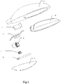
- a sodium lamp is as shown in Fig. 1 . It consists of a casing 1, a bracket 2, a ballast 3, a lamp base bracket 4, a lamp base 5, a light source tube 6, a cover 7, and a reflector 8.
- the casing 1 is divided into an upper casing and a lower casing, and the upper casing and the lower casing form a hollow casing 1.
- the reflector 8 is fixedly mounted on the lower casing by screws, and is located inside the casing 1.
- a circular opening is provided at the tail of the reflector 8 for the light source tube 6 to pass through.
- the cover 7 is fixedly mounted on the lower casing by screws and the pressers corresponding to the reflector 8, and is located outside the casing 1.
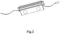
- the ballast 3 is fixedly mounted on the bracket 2 by screws.
- the lamp base bracket 4 is externally attached to the bracket 2.
- the lamp base 5 is mounted on the lamp base bracket 4 and is connected to the light source tube 6.
- the bracket 2 is fixed to the lower casing of the casing 1 by screws.
- the lamp base bracket 4, the lamp base 5 and the light source tube 6 pass through the circular opening at the tail of the reflector 8 and are located in a closed space formed by the reflector 8 and the cover 7.
- the working principle of the sodium lamp is as follows: when the bulb is switched on, an arc is generated between the electrodes at the two ends of the light source tube 6; due to the high temperature of the arc, the liquid sodium-mercury amalgam within the tube is evaporated into mercury vapour and sodium vapour; the electrons emitted from the cathode impinge on the atoms of the discharge material during the movement toward the anode;the atoms obtain the energy for ionization or excitation, and then return to the ground state from the excited state; or the ionized atoms are excited, and then return to the ground state,forming an infinite loop.At this time, excess energy is released in the form of light radiation, producing light.
- sodium lamps are the most commonly used street lamps, they still have the following defects: 1. high power consumption and low power efficiency; 2. low colour temperature and poor colour rendering; 3. low light source utilization ratio; 4. long start-up time, and inability to be started continuously; 5. not environment friendly (containing mercury); 6. short service life; and 7. complex disassembly, and inconvenient replacement and maintenance.
- the light source tube used in a sodium lamp emits light 360 degree, a reflector is provided for the reflection of a part of the light and a large amount of light energy will be wasted in the reflection process.Although the sodium lamp can meet the lighting requirements, it cannot solve the problem of energy saving in the urban road construction process.
- an LED lamp can save about 55% of the energy.
- the colour temperature of the LED lamp can be flexibly selected from a range of 1900K to 7000K, and the colour rendering index can be as high as 70 or above, while the colour of the light emitted by the traditional sodium lamp is yellow with a low colour rendering index.
- the bulb structure of the sodium lamp determines its low light output rate, which is only about 60%, but the LED lamp has a high light output rate, which can be up to 88%-95%.
- a bulb of a high-pressure sodium lamp has long start-up time and needs a certain time interval before starting up again, while the LED lamp does not have the start-up delay problem, can be turned on and work at any time.
- LED is a solid light source without any gas.
- the LED lamp does not contain mercury or lead, has no ultraviolet ray, and will neither cause harm to the human body nor pollute the environment (it can also be recycled and reused).
- the theoretical life of an LED is about 100,000 hours and the theoretical life of the traditional sodium lamp is only about 6,000 hours.
- LED street lamps have many advantages over sodium lamps, they still have some shortcomings. First of all, regardless of whether it is a high-power LED street lamp or a high-temperature sodium lamp, due to structural limitations, it is very inconvenient to replace the lamp, especially for the large-scaled replacement in urban road construction, which will seriously restrict the construction and development of street lamps. The realization of quick and convenient replacement is an urgent problem to be solved.
- the present invention provides a novel LED light source module, an LED module assembly, and a graphene heat-dissipation LED lamp.
- a novel LED light source module By adding and encapsulating a graphene heat-conducting material to the light source of the LED street lamp, the heat conduction efficiency of the light source is improved and the service life is prolonged, and in addition, the lighting efficiency of the LED street lamp is further improved.
- the present invention can be quickly installed without a disassembling tool, by providing standalone modules and using a quick connector.
- the graphene heat-dissipation LED lamp provided in the present invention comprises an LED light source module, a power supply module, a lamp housing and an optional waterproof power strip.
- the LED light source modules are connected to the power supply module through the waterproof power strip to form an LED module assembly.
- the LED light source module and the power supply module are connected directly to form an LED module assembly.
- the LED light source module comprises a sunflower radiator.
- a block structure formed of a graphene phase-change material is filled in the middle of the sunflower radiator.
- the surface of the sunflower radiator is coated with a graphene-containing fluororesin material.
- the LED light source of the LED light source module is connected to the sunflower radiator through graphene-containing heat-conducting silicone grease.
- the LED module assembly is fixed to the lamp housing by one or 2 or more screws and pressersto form an LED street lamp base.
- the number of the LED light source modules can beseveral, for example, one, two, three, four, five, six or more.
- the LED light source module comprises a lens, a rubber ring, a pressure ring, an LED light source, a sunflower radiator, a back cover, a platform, a block structure formed of a graphene phase-change material, a screw and a waterproof quick connector.
- the LED light source in the LED light source module, is fixed to the platform of the sunflower radiator, and the graphene-containing heat-conducting silicone grease is coated between the LED light source and the platform.
- the sunflower radiator is a hollow heat-dissipating structure with toothed radial fins, and the graphene phase-change material is poured into the hollow portion of the sunflower radiator and is solidified to form the block structure.
- the hollow portion of the sunflower radiator is sealed by the platform and the back cover.
- the lens is fastened to the sealing rubber ring, and the pressing ring is fixed to the sunflower radiator platform by screws, so as to closely attach the lens and the sealing rubber ring to the sunflower radiator platform.
- the waterproof quick connector connects the light source to the waterproof quick connector of the power supply through a waterproof through hole reserved in the sunflower radiator.
- the present invention provides a new LED light source module, an LED module assembly, and a graphene heat-dissipation LED lamp.
- the present invention adds several types of graphene-containing heat-dissipating materials to the LED module, so as to improve its heat conduction efficiency and prolong its service life.
- the LED light source module, the LED module assembly and the graphene heat-dissipation LED lamp of the present invention further improve the lighting performance of the LED lamp.
- the present invention can be quickly installed without a disassembling tool, by providing standalone modules and using a quick connector.
- the graphene heat-dissipation LED lamp provided by the present invention comprises one or 2 or more LED light source modules and a power supply module, a lamp housing and an optional waterproof power strip.
- the LED light source module and the power supply module are connected to form an LED module assembly.
- Two or more light source modules are connected to the power supply module through the waterproof power strip to form an LED module assembly.
- the LED module assembly is fixed to the lamp housing by several screws and pressers to form an LED street lamp base.
- the number of the LED light source modules is preferentially one to six.
- the LED light source module comprises a lens, a rubber ring, a pressure ring, an LED light source, graphene-containing heat-conducting silicone grease, a sunflower radiator containing a graphene coating, a back cover, a platform, a block structure formed of a graphene phase-change material, a screw and a waterproof quick connector.
- the sunflower radiator is a hollow heat-dissipating structure with toothed radial fins.
- the graphene phase-change material is poured into a hollow portion of the sunflower radiator and is solidified to form a cylinder, and the hollow portion of the sunflower radiator will be sealed by the platform and the back cover.
- the light source is fixed on the platform of the sunflower radiator by screws.
- a heat-conducting silicone grease composition prepared using a graphene-containing material is applied between the light source and the platform. This heat-conducting silicone grease composition will connect the light source and the sunflower radiator platform closely after solidification.
- the lens is fastened to the sealing rubber ring, and the pressing ring is fixed to the sunflower radiator platform by screws, so as to closely attach the lens and the sealing rubber ring to the sunflower radiator platform.
- the waterproof quick connector connects the light source to the waterproof quick connector of the power supply through a waterproof through hole reserved in the sunflower radiator.
- the one or 2 or more light source modules are fixed to a light source liner plate by screws with
- the lens is a high borosilicate glass lens which has a light transmittance of up to about 95% and can reduce the LED light loss.
- the light source provided by the present invention is a COB light source.
- the light source and the platform of the sunflower radiator are connected by graphene-containing heat-conducting silicone grease, so that the temperature difference between the radiator and the light source is controlled within 2°C, the heat conduction efficiency of the LED chip is greatly improved, and the temperature of the light source chip can be maintained within a good range, thereby reducing the light decay of the LED chip and prolonging the service life of the LED.
- the graphene-containing heat-conducting silicone grease composition will solidify after bonding, and will have stable properties which are insusceptible to the influences of external environment, so that the light source chip and the radiator can be closely connected.
- the state of ordinary heat-conducting silicone grease tends to be affected by temperature, which results in dissociation and thereby causes a gap between the chip and the heat-dissipating platform, which reduces the heat dissipation efficiency.
- the heat dissipation coefficient of the graphene-containing heat-conducting silicone grease is 3.0W/m ⁇ k or greater, while the heat dissipation coefficient of the traditional heat-conducting silicone grease is only about 1.0W/m ⁇ k, so that the use of the graphene-containing heat-conducting silicone grease can increase the heat transfer performance by more than 1.5 times.
- the service life of the graphene-containing heat-conducting silicone grease is about 10 years. This is much longer than that of the traditional heat-conducting silicone grease, which is about 2 years. Therefore, the use of the graphene-containing heat-conducting silicone grease enables the sunflower radiator to better dissipate the heat of the light source.
- the use of the graphene-containing heat-conducting silicone grease material has already been disclosed in the applicant's prior patent CN201210119361.9 and is not described in detail herein.
- a graphene phase-change nano material for heat storage is built in the cavity of the sunflower radiator, and the graphene phase-change material can also realize the effects of heat storage and temperature unification, thereby further improving the heat dissipation efficiency of the radiator.
- the graphene phase-change nano material for heat storage provided by the present invention has already been disclosed in the applicant's prior patent CN201310714156.1 , and the inner phase-change layer used in that patent is prepared using various existing phase-change materials, including solid-liquid phase-change materials, liquid-gas phase-change materials, solid-solid phase-change materials and solid-gas phase-change materials, the specific material being organic or inorganic.
- phase-change material which can be realized by simply storing the solid-liquid phase-change material in the phase-change layer, and the phase-change material has the property of changing form with temperature while providing latent heat.
- phase change where the phase-change material changes its state from solid to liquid or from liquid to solid, the phase-change material will absorb or release a large amount of latent heat.
- the phase-change material has the ability to change its physical state within a certain temperature range, so that it can maintain a certain temperature for a long time.
- phase-change temperature range of the solid-liquid phase-change material is 0-200°C, and the material is preferably one or more of the following phase-change materials: paraffin, microcrystalline wax, liquid paraffin, polyethylene wax, semi-refined paraffin, and polyethylene glycol 6000, etc.
- the surface of the sunflower radiator provided by the present invention is coated with a graphene-containing fluororesin composite material (also referred to as a RLCP graphene-fluororesin composite material) to enhance infrared radiation and improve the heat dissipation efficiency.
- a graphene-containing fluororesin composite material also referred to as a RLCP graphene-fluororesin composite material
- the radiation coefficient of the surface of an ordinary radiator is 0.2. After adding a coating of the RLCP graphene-fluororesin composite material, the radiation coefficient increases to 0.7, and the outward radiation and heat storage are greatly enhanced.
- the RLCP graphene-fluororesin composite material used has already been disclosed in the applicant's prior patent CN201310089504.0 , and will not be described in detail herein.
- the power supply module comprises a power supply and a power supply liner plate.
- the power supply and the power supply liner plate are connected by screws to form a power supply module.
- the LED module provided by the present invention, three different types of graphene heat-conducting materials are added, so that the heat conduction efficiency of the whole LED is improved, the product performance of the LED module is improved by about 30% compared with traditional LED lamps, and, in combination with the highly efficient and energy-saving characteristics of the LED, the light efficiency is improved by 200% compared with traditional sodium lamps.
- the international protection marking of the whole LED lamp provided by the present invention can easily reach IP67 through the use of waterproof quick connectors, sealing rings, pressing rings, etc., which can ensure the normal operation of the lamps in various environments.
- the light source and the power supply provided respectively as independent modules.
- the LED light source module and the power supply module in the present invention are connected to each other by a quick connector, thus having the advantages of convenient installation and easy maintenance.
- the use of a sunflower radiator with high heat conduction efficiency, the heat dissipation efficiency of the entire lamp can be further improved.
- the graphene heat-dissipation LED lamp comprises two LED light source modules and a power supply module (wherein the power supply module comprises a driving power supply 21 and a power supply liner plate 20), a lamp housing 9 and a waterproof power strip 22, wherein the two LED light source modules are located inside the lamp housing.
- the light source module is connected to the power supply module through the waterproof power strip 22 to form an LED module assembly.
- the LED module assembly is fixed to the lamp housing by screws and pressers to form an LED street lamp base.
- the number of the LED light source modules is two.
- the two LED light source modules are fixed inside the lamp housing 9 by a tray 19.
- the LED light source module comprises a lens 16, a rubber ring 17, a pressure ring 18, an LED light source 15, a graphene-containing heat-conducting silicone grease, a sunflower radiator 13, a back cover 10, a platform 14, a graphene phase-change material 23, a screw and a waterproof quick connector 12.
- the waterproof quick connector 12 in the LED light source module is connected to the waterproof power strip 22, and the waterproof quick connectors 12 in several light source modules are usually connected to one and the same waterproof power strip 22.
- Fig. 3 shows a case where two light source modules are included. It can be understood by those skilled in the art that when the number of the light source module is one, the light source module is directly connected to the power supply module.
- the sunflower radiator 13 is a hollow heat-dissipating structure with toothed radial fins.
- the graphene phase-change material 23 is poured into a hollow portion of the sunflower radiator and is solidified to form a cylinder, and the hollow portion of the sunflower radiator 13 will be sealed by the platform 14 and the back cover 10.
- the LED light source 15 is fixed on the platform 14 of the sunflower radiator by screws, and the heat-conducting silicone grease prepared by a graphene material is applied between the light source and the platform. After solidification, this heat-conducting silicone grease will connect the light source and the sunflower radiator platform closely.
- the lens 16 is fastened to the sealing rubber ring 17, and the pressing ring 18 is fixed to the sunflower radiator 13 platform by screws, so as to closely attach the lens 16 and the sealing rubber ring 17 to the sunflower radiator platform 14.
- the waterproof quick connector 12 connects the light source to the waterproof power strip 22 of the power supply through a waterproof through hole reserved in the sunflower radiator 13.
- the light source modules are fixed to the light source liner plate by screws with washers and spring pads.
- Fig. 4 is an overall schematic diagram of the LED light source module after assembling.
- the graphene phase-change material is specifically prepared as follows: the additive components used and their mass ratios are: carbon nanotubes, graphene, particulates, and fumed silica at a mass ratio of 1:10:8:1, and the mass ratio of all the additive components to the phase-change material described later is 1:4.
- the purity of the carbon nanotubes is ⁇ 95wt%, and the ash content is ⁇ 0.2wt%.
- the particulate is alumina (Al 2 O 3 ) and the average particle size is 10 ⁇ m.
- the phase-change material is paraffin and the phase-change temperature is 70°C.
- paraffin was heated to complete melting, and then carbon nanotubes, graphene and particulates at a mass ratio of 1: 10: 8 are poured into the paraffin melt liquid for premixing.
- the mixture was stirred until homogeneously mixed, fumed silica of the required mass was added slowly; it was further stirred until homogeneously mixed, and the eventual phase-change material is obtained after cooling down.
- the graphene-containing heat-conducting silicone grease is specifically prepared as follows: the additive components used and their mass ratios are: carbon nanotubes, graphene, and particulates at a mass ratio of 1: 6: 3, and the volume ratio of all additive components to silicone oil is 6: 4.
- the purity of the carbon nanotubes is ⁇ 95wt%, and the ash content is ⁇ 0.2wt%.
- the particulate is a paraffin-coated phase-change capsule, and the paraffin-coated material is alumina with a phase-change temperature of 29°C and an average particle size of 60 ⁇ m.
- the silicone oil is a mixture of dimethicone and hydrogen-containing silicone oil, with a viscosity of 500,000cSt at 25°C.
- the graphene and particulates at a mass ratio of 6: 3 were poured into a small amount of silicone oil for premixing, and under the condition of mechanical stirring, carbon nanotubes of the required mass were slowly added, and silicone oil was replenished as needed until the required content of silicone oil was reached. After mechanical stirring for further half an hour, the mixture was milled for one hour using a roller mill to obtain the eventual silicone grease.
- the RLCP graphene-fluororesin composite material was specifically prepared as follows: A target coating material was formed by mixing the following materials (by mass percent) in steps and stirring them evenly under the condition of 800-1000rpm at room temperature: 50% fluorosilicone resin (provided by Shanghai Huiyan New Materials Co., Ltd), 40% acrylic thinner, 4% electron-transferring organic compound of polypropylene, 1% graphene, 1% carbon nanotube, 1% titanium dioxide, and 3% a curing agent of epoxy resin.
- the RLCP graphene-fluororesin composite material was applied to the surface of the sunflower radiator by the following method: performing degreasing and decontamination treatments on the surface of the radiator to be sprayed, fully stirring the target coating material and then pouring it into a spray gun, setting the pressure of the spray gun to 0.4MPa, aiming at the target surface at a distance of 10-20cm, and spraying it two to three times to make the coating evenly cover the surface of the object.
- the coating was even and glossy, and its thickness could be optimized as required.
- the coating could be naturally air-dried for 12 hours or baked in an oven for 10 minutes for quick solidification.
- the light source used in the following examples is a COB light source.
- Example 1 LED lamp containing graphene heat-conducting silicone grease
- Comparative sample a 160 ⁇ 70mm sunflower radiator of reference design and a 30W integrated light source were used, the light source and the platform being connected by a thermal paste from Thermalright, Taiwan, with no surface treatment for the cavity interior and the heat sink.
- Experimental sample a 160 ⁇ 70mm sunflower radiator of reference design identical to the comparative sample, and a 30W integrated light source identical to the comparative sample were used, the light source and the platform being connected by the above-mentioned graphene-containing heat-conducting silicone grease, with no surface treatment for the cavity interior and the heat sink.
- Comparative sample the above-mentioned 160 ⁇ 70mm sunflower radiator of reference design and the above-mentioned 30W integrated light source were used, the light source and the platform being connected by the above-mentioned thermal paste from Thermalright, Taiwan, with no surface treatment for the cavity interior and the heat sink.
- Comparative sample the above-mentioned 160 ⁇ 70mm sunflower radiator of reference design and a 90W integrated light source were used, the light source and the platform being connected by the above-mentioned thermal paste from Thermalright, Taiwan, with no surface treatment for the cavity interior and the heat sink.
- Example 1 When reaching a steady state after 40 minutes , the experimental sample of Example 1 had a chip temperature of 34.7°C and a heat sink temperature of 34.8°C, while the comparative sample of Example 1 had a chip temperature of 36.8°C and a heat sink temperature of 36.8°C. It can be seen that, compared with the Thermalright thermal paste, the graphene-containing heat-conducting silicone grease in the same time reduced the chip temperature by 2°C further, which was basically consistent with the data obtained by the heat conductivity coefficient measurement method.
- Example 2 the experimental sample and the comparative sample of Example 2 were tested according to the above-mentioned test conditions.
- the chip temperature of the comparative sample was 41°C and the temperature difference between the chip and the fins was 3°C, while the chip temperature of the experimental sample was only 38°C, and there was no temperature difference between the chip and the fins.
- the experimental sample and the comparative sample of Example 3 were tested according to the above-mentioned test conditions.
- the temperature rise of the chip in the sunflower heat dissipation system of the experimental sample of Example 3 was significantly slower than that of the comparative sample.
- the final temperature of the experimental sample was 7°C lower, which means that the system has a higher heat dissipation capability after the material of the present invention is sprayed.
- the surface temperature of the heat sink of the experimental sample was about 3°C higher than the surface temperature of the heat sink that was not sprayed. It can be seen from the temperature difference between the chip and the heat sink that the temperature difference for the experimental samples is about 1°C, and the temperature difference for the comparative samples is up to 10.6°C. It is indicated that the sunflower heat dissipation system sprayed with the graphene-containing fluororesin material of the present invention has a better heat radiation capability and lowers the temperature of the LED chip.
- Example 4 Further, the sample of Example 4 was tested, and the temperature rise of the substrate of the 90W integrated light source was only 31.6°C after reaching a steady state. The temperature difference between the substrate and the lowest temperature of the heat sink was in the range of 1°C, and the temperature uniformity was excellent.
- the surface of the sunflower radiator in this example is coated with a RLCP graphene-fluororesin composite material so as to be able to enhance infrared radiation, and the experimental results showed that the application of the coating had significantly improved the heat dissipation efficiency.
- the radiation coefficient of the surface of an ordinary radiator is 0.2. After adding a graphene coating, the radiation coefficient increases to 0.7, and the outward radiation and heat storage are greatly enhanced.
- the graphene phase-change nano material for heat storage is built in the cavity of the sunflower radiator, and according to the experimental results, the heat dissipation efficiency of the radiator can be further improved by using the phase-change material, and the volume of the radiator is reduced under the same heat dissipation condition, making the LED module lighter and easier to install.
- the light source module provided by the present invention adds three types of graphene heat-conducting materials through encapsulation, so that the heat conduction efficiency of the whole LED is improved, and the light efficiency is increased by 200% compared with traditional sodium lamps, or by about 30% compared with traditional LED lamps.
Landscapes
- Engineering & Computer Science (AREA)
- General Engineering & Computer Science (AREA)
- Physics & Mathematics (AREA)
- Microelectronics & Electronic Packaging (AREA)
- Optics & Photonics (AREA)
- Non-Portable Lighting Devices Or Systems Thereof (AREA)
- Arrangement Of Elements, Cooling, Sealing, Or The Like Of Lighting Devices (AREA)
Description
- The present invention belongs to the technical field of illumination, and in particular relates to a new Graphene heat-dissipation LED lamp.
- In the process of urbanization, street lamps represent a very important link in the construction. According to statistics, the consumption for lighting accounts for about 20% of the national electricity consumption currently. China's annual electricity for lighting is close to 250 billion kWh, a large part of which is due to the power consumption of urban street lamps. Reducing the electricity consumption for road lighting is an important part of energy conservation in urban construction.
- At present, the most commonly used lighting fixtures on urban roads are sodium lamps.A sodium lamp as a street lamp provides good road visibility at night. Its orange light is penetrating and soft in the fog, and the objects under this kind of light can be seen clearly. Therefore, sodium gas lamps are used to reduce traffic accidents on main roads and for artificial lighting.
- The structure of a sodium lamp is as shown in
Fig. 1 . It consists of acasing 1, abracket 2, aballast 3, alamp base bracket 4, alamp base 5, alight source tube 6, acover 7, and areflector 8. Thecasing 1 is divided into an upper casing and a lower casing, and the upper casing and the lower casing form ahollow casing 1. Thereflector 8 is fixedly mounted on the lower casing by screws, and is located inside thecasing 1. A circular opening is provided at the tail of thereflector 8 for thelight source tube 6 to pass through. Thecover 7 is fixedly mounted on the lower casing by screws and the pressers corresponding to thereflector 8, and is located outside thecasing 1. - As shown in
Fig. 2 , theballast 3 is fixedly mounted on thebracket 2 by screws. Thelamp base bracket 4 is externally attached to the bracket 2.Thelamp base 5 is mounted on thelamp base bracket 4 and is connected to the light source tube 6.Thebracket 2 is fixed to the lower casing of thecasing 1 by screws.Thelamp base bracket 4, thelamp base 5 and thelight source tube 6 pass through the circular opening at the tail of thereflector 8 and are located in a closed space formed by thereflector 8 and thecover 7. - The working principle of the sodium lamp is as follows: when the bulb is switched on, an arc is generated between the electrodes at the two ends of the
light source tube 6; due to the high temperature of the arc, the liquid sodium-mercury amalgam within the tube is evaporated into mercury vapour and sodium vapour; the electrons emitted from the cathode impinge on the atoms of the discharge material during the movement toward the anode;the atoms obtain the energy for ionization or excitation, and then return to the ground state from the excited state; or the ionized atoms are excited, and then return to the ground state,forming an infinite loop.At this time, excess energy is released in the form of light radiation, producing light. - Although sodium lamps are the most commonly used street lamps, they still have the following defects: 1. high power consumption and low power efficiency; 2. low colour temperature and poor colour rendering; 3. low light source utilization ratio; 4. long start-up time, and inability to be started continuously; 5. not environment friendly (containing mercury); 6. short service life; and 7. complex disassembly, and inconvenient replacement and maintenance.
- Since the light source tube used in a sodium lamp emits light 360 degree, a reflector is provided for the reflection of a part of the light and a large amount of light energy will be wasted in the reflection process.Although the sodium lamp can meet the lighting requirements, it cannot solve the problem of energy saving in the urban road construction process.
- With the establishment of a resource-conserving and environment-friendly society in recent years, the concept of "green lighting" is gradually gaining popularity. With the continuous advancement of science and technology, and the rapid development of application technology of semiconductor materials, low-power LED light sources have been widely used in landscape lighting, and high-power LED street lamps have also attracted more and more attention from all sides.
- Compared with the traditional sodium lamp, an LED lamp can save about 55% of the energy. The colour temperature of the LED lamp can be flexibly selected from a range of 1900K to 7000K, and the colour rendering index can be as high as 70 or above, while the colour of the light emitted by the traditional sodium lamp is yellow with a low colour rendering index. The bulb structure of the sodium lamp determines its low light output rate, which is only about 60%, but the LED lamp has a high light output rate, which can be up to 88%-95%. A bulb of a high-pressure sodium lamp has long start-up time and needs a certain time interval before starting up again, while the LED lamp does not have the start-up delay problem, can be turned on and work at any time. LED is a solid light source without any gas.The LED lamp does not contain mercury or lead, has no ultraviolet ray, and will neither cause harm to the human body nor pollute the environment (it can also be recycled and reused). The theoretical life of an LED is about 100,000 hours and the theoretical life of the traditional sodium lamp is only about 6,000 hours.
- Although LED street lamps have many advantages over sodium lamps, they still have some shortcomings. First of all, regardless of whether it is a high-power LED street lamp or a high-temperature sodium lamp, due to structural limitations, it is very inconvenient to replace the lamp, especially for the large-scaled replacement in urban road construction, which will seriously restrict the construction and development of street lamps. The realization of quick and convenient replacement is an urgent problem to be solved.
- On the other hand, for high-power LED street lamps, heat dissipation is also very important for their application.The performance life of an LED is greatly affected by temperature, and thus heat dissipation is a non-negligible problem. If the heat dissipation problem cannot be solved, the loss of the LED street lamp will be intensified, which will affect its normal use. Document
EP 2876357 A1 discloses an LED light source module according to the preamble ofclaim 1. - In order to overcome the above-mentioned technical problems, the present invention provides a novel LED light source module, an LED module assembly, and a graphene heat-dissipation LED lamp. By adding and encapsulating a graphene heat-conducting material to the light source of the LED street lamp, the heat conduction efficiency of the light source is improved and the service life is prolonged, and in addition, the lighting efficiency of the LED street lamp is further improved. In contrast to the inconvenience in disassembly and replacement of traditional street lamps, the present invention can be quickly installed without a disassembling tool, by providing standalone modules and using a quick connector.
- The graphene heat-dissipation LED lamp provided in the present invention comprises an LED light source module, a power supply module, a lamp housing and an optional waterproof power strip.
- When the number of the LED light source modules is 2 or more, the LED light source modules are connected to the power supply module through the waterproof power strip to form an LED module assembly.
- When the number of the light source module is one, the LED light source module and the power supply module are connected directly to form an LED module assembly.
- According to the invention, the LED light source module comprises a sunflower radiator.
- According to the invention, a block structure formed of a graphene phase-change material is filled in the middle of the sunflower radiator.
- According to the invention, the surface of the sunflower radiator is coated with a graphene-containing fluororesin material.
- According to the invention, in the LED light source module, the LED light source of the LED light source module is connected to the sunflower radiator through graphene-containing heat-conducting silicone grease.
- In a specific embodiment, the LED module assembly is fixed to the lamp housing by one or 2 or more screws and pressersto form an LED street lamp base.
- In a specific embodiment, the number of the LED light source modules can beseveral, for example, one, two, three, four, five, six or more.
- In a specific embodiment, the LED light source module comprises a lens, a rubber ring, a pressure ring, an LED light source, a sunflower radiator, a back cover, a platform, a block structure formed of a graphene phase-change material, a screw and a waterproof quick connector.
- In a specific embodiment, in the LED light source module, the LED light source is fixed to the platform of the sunflower radiator, and the graphene-containing heat-conducting silicone grease is coated between the LED light source and the platform.
- In a specific embodiment, the sunflower radiator is a hollow heat-dissipating structure with toothed radial fins, and the graphene phase-change material is poured into the hollow portion of the sunflower radiator and is solidified to form the block structure.
- In a specific embodiment, the hollow portion of the sunflower radiator is sealed by the platform and the back cover.
- In a specific embodiment, the lens is fastened to the sealing rubber ring, and the pressing ring is fixed to the sunflower radiator platform by screws, so as to closely attach the lens and the sealing rubber ring to the sunflower radiator platform.
- In a specific embodiment, the waterproof quick connector connects the light source to the waterproof quick connector of the power supply through a waterproof through hole reserved in the sunflower radiator.
- The present invention provides a new LED light source module, an LED module assembly, and a graphene heat-dissipation LED lamp. The present invention adds several types of graphene-containing heat-dissipating materials to the LED module, so as to improve its heat conduction efficiency and prolong its service life. In addition, the LED light source module, the LED module assembly and the graphene heat-dissipation LED lamp of the present invention further improve the lighting performance of the LED lamp. In contrast to the inconvenience in the disassembly and replacement of traditional street lamps, the present invention can be quickly installed without a disassembling tool, by providing standalone modules and using a quick connector.
-
-
Fig. 1 is an overall schematic diagram of a high-pressure sodium lamp in the prior art. -
Fig. 2 is a schematic diagram of a ballast of a traditional sodium lamp. -
Fig. 3 is a schematic overall exploded view of a graphene heat-dissipation LED lamp of the present invention. -
Fig. 4 is an overall schematic diagram of a light source module of the present invention. -
Fig. 5 is a schematic diagram of the sodium lamp after retrofitting. - The graphene heat-dissipation LED lamp provided by the present invention comprises one or 2 or more LED light source modules and a power supply module, a lamp housing and an optional waterproof power strip.
- When the number of the light source modules is one, the LED light source module and the power supply module are connected to form an LED module assembly.
- Two or more light source modules are connected to the power supply module through the waterproof power strip to form an LED module assembly.
- The LED module assembly is fixed to the lamp housing by several screws and pressers to form an LED street lamp base.
- The number of the LED light source modules is preferentially one to six.
- The LED light source module comprises a lens, a rubber ring, a pressure ring, an LED light source, graphene-containing heat-conducting silicone grease, a sunflower radiator containing a graphene coating, a back cover, a platform, a block structure formed of a graphene phase-change material, a screw and a waterproof quick connector.
- The sunflower radiator is a hollow heat-dissipating structure with toothed radial fins. The graphene phase-change material is poured into a hollow portion of the sunflower radiator and is solidified to form a cylinder, and the hollow portion of the sunflower radiator will be sealed by the platform and the back cover. The light source is fixed on the platform of the sunflower radiator by screws. A heat-conducting silicone grease composition prepared using a graphene-containing material is applied between the light source and the platform. This heat-conducting silicone grease composition will connect the light source and the sunflower radiator platform closely after solidification. The lens is fastened to the sealing rubber ring, and the pressing ring is fixed to the sunflower radiator platform by screws, so as to closely attach the lens and the sealing rubber ring to the sunflower radiator platform. The waterproof quick connector connects the light source to the waterproof quick connector of the power supply through a waterproof through hole reserved in the sunflower radiator. The one or 2 or more light source modules are fixed to a light source liner plate by screws with washers and elastic pads.
- The lens is a high borosilicate glass lens which has a light transmittance of up to about 95% and can reduce the LED light loss.
- The light source provided by the present invention is a COB light source. The light source and the platform of the sunflower radiator are connected by graphene-containing heat-conducting silicone grease, so that the temperature difference between the radiator and the light source is controlled within 2°C, the heat conduction efficiency of the LED chip is greatly improved, and the temperature of the light source chip can be maintained within a good range, thereby reducing the light decay of the LED chip and prolonging the service life of the LED.
- The graphene-containing heat-conducting silicone grease composition will solidify after bonding, and will have stable properties which are insusceptible to the influences of external environment, so that the light source chip and the radiator can be closely connected. On the other hand, the state of ordinary heat-conducting silicone grease tends to be affected by temperature, which results in dissociation and thereby causes a gap between the chip and the heat-dissipating platform, which reduces the heat dissipation efficiency. Generally, the heat dissipation coefficient of the graphene-containing heat-conducting silicone grease is 3.0W/m·k or greater, while the heat dissipation coefficient of the traditional heat-conducting silicone grease is only about 1.0W/m·k, so that the use of the graphene-containing heat-conducting silicone grease can increase the heat transfer performance by more than 1.5 times. The service life of the graphene-containing heat-conducting silicone grease is about 10 years. This is much longer than that of the traditional heat-conducting silicone grease, which is about 2 years. Therefore, the use of the graphene-containing heat-conducting silicone grease enables the sunflower radiator to better dissipate the heat of the light source. The use of the graphene-containing heat-conducting silicone grease material has already been disclosed in the applicant's prior patent
CN201210119361.9 - In the present invention, a graphene phase-change nano material for heat storage is built in the cavity of the sunflower radiator, and the graphene phase-change material can also realize the effects of heat storage and temperature unification, thereby further improving the heat dissipation efficiency of the radiator. The graphene phase-change nano material for heat storage provided by the present invention has already been disclosed in the applicant's prior patent
CN201310714156.1 - The surface of the sunflower radiator provided by the present invention is coated with a graphene-containing fluororesin composite material (also referred to as a RLCP graphene-fluororesin composite material) to enhance infrared radiation and improve the heat dissipation efficiency. The radiation coefficient of the surface of an ordinary radiator is 0.2. After adding a coating of the RLCP graphene-fluororesin composite material, the radiation coefficient increases to 0.7, and the outward radiation and heat storage are greatly enhanced. The RLCP graphene-fluororesin composite material used has already been disclosed in the applicant's prior patent
CN201310089504.0 - The power supply module comprises a power supply and a power supply liner plate. The power supply and the power supply liner plate are connected by screws to form a power supply module.
- In the LED module provided by the present invention, three different types of graphene heat-conducting materials are added, so that the heat conduction efficiency of the whole LED is improved, the product performance of the LED module is improved by about 30% compared with traditional LED lamps, and, in combination with the highly efficient and energy-saving characteristics of the LED, the light efficiency is improved by 200% compared with traditional sodium lamps.
- The international protection marking of the whole LED lamp provided by the present invention can easily reach IP67 through the use of waterproof quick connectors, sealing rings, pressing rings, etc., which can ensure the normal operation of the lamps in various environments. In the present invention, the light source and the power supply provided respectively as independent modules. In contrary to the traditional LED lamps in which many components are fixedly connected to each other, the LED light source module and the power supply module in the present invention are connected to each other by a quick connector, thus having the advantages of convenient installation and easy maintenance. In addition, the use of a sunflower radiator with high heat conduction efficiency, the heat dissipation efficiency of the entire lamp can be further improved.
- The embodiments of the present invention will be described in detail below with reference to the examples and the accompanying drawings, so that the implementation process in which the technical means of the present invention are applied to solve the technical problems and the technical effects are achieved can be comprehensively understood and realized.
- As shown in
Fig. 3 andFig. 5 , in the graphene heat-dissipation LED lamp provided by the present invention, the graphene heat-dissipation LED lamp comprises two LED light source modules and a power supply module (wherein the power supply module comprises a drivingpower supply 21 and a power supply liner plate 20), alamp housing 9 and awaterproof power strip 22, wherein the two LED light source modules are located inside the lamp housing. The light source module is connected to the power supply module through thewaterproof power strip 22 to form an LED module assembly. The LED module assembly is fixed to the lamp housing by screws and pressers to form an LED street lamp base. As shown inFig. 5 , the number of the LED light source modules is two. In addition, as shown inFig. 3 , the two LED light source modules are fixed inside thelamp housing 9 by atray 19. - The LED light source module comprises a
lens 16, arubber ring 17, apressure ring 18, anLED light source 15, a graphene-containing heat-conducting silicone grease, asunflower radiator 13, aback cover 10, aplatform 14, a graphene phase-change material 23, a screw and a waterproofquick connector 12. - When installing the graphene heat-dissipation LED lamp provided by the present invention, the waterproof
quick connector 12 in the LED light source module is connected to thewaterproof power strip 22, and the waterproofquick connectors 12 in several light source modules are usually connected to one and the samewaterproof power strip 22. -
Fig. 3 shows a case where two light source modules are included. It can be understood by those skilled in the art that when the number of the light source module is one, the light source module is directly connected to the power supply module. - The
sunflower radiator 13 is a hollow heat-dissipating structure with toothed radial fins. The graphene phase-change material 23 is poured into a hollow portion of the sunflower radiator and is solidified to form a cylinder, and the hollow portion of thesunflower radiator 13 will be sealed by theplatform 14 and theback cover 10. TheLED light source 15 is fixed on theplatform 14 of the sunflower radiator by screws, and the heat-conducting silicone grease prepared by a graphene material is applied between the light source and the platform. After solidification, this heat-conducting silicone grease will connect the light source and the sunflower radiator platform closely. Thelens 16 is fastened to the sealingrubber ring 17, and thepressing ring 18 is fixed to thesunflower radiator 13 platform by screws, so as to closely attach thelens 16 and the sealingrubber ring 17 to thesunflower radiator platform 14. The waterproofquick connector 12 connects the light source to thewaterproof power strip 22 of the power supply through a waterproof through hole reserved in thesunflower radiator 13. The light source modules are fixed to the light source liner plate by screws with washers and spring pads.Fig. 4 is an overall schematic diagram of the LED light source module after assembling. - The materials used in the following examples are as follows, which are commercially available.
- The graphene phase-change material is specifically prepared as follows:
the additive components used and their mass ratios are: carbon nanotubes, graphene, particulates, and fumed silica at a mass ratio of 1:10:8:1, and the mass ratio of all the additive components to the phase-change material described later is 1:4. - The purity of the carbon nanotubes is ≥95wt%, and the ash content is ≤0.2wt%.
- The particulate is alumina (Al2O3) and the average particle size is 10µm.
- The phase-change material is paraffin and the phase-change temperature is 70°C.
- The paraffin was heated to complete melting, and then carbon nanotubes, graphene and particulates at a mass ratio of 1: 10: 8 are poured into the paraffin melt liquid for premixing. The mixture was stirred until homogeneously mixed, fumed silica of the required mass was added slowly; it was further stirred until homogeneously mixed, and the eventual phase-change material is obtained after cooling down.
- The graphene-containing heat-conducting silicone grease is specifically prepared as follows:
the additive components used and their mass ratios are: carbon nanotubes, graphene, and particulates at a mass ratio of 1: 6: 3, and the volume ratio of all additive components to silicone oil is 6: 4. - The purity of the carbon nanotubes is ≥95wt%, and the ash content is ≤0.2wt%.
- The particulate is a paraffin-coated phase-change capsule, and the paraffin-coated material is alumina with a phase-change temperature of 29°C and an average particle size of 60µm.
- The silicone oil is a mixture of dimethicone and hydrogen-containing silicone oil, with a viscosity of 500,000cSt at 25°C.
- The graphene and particulates at a mass ratio of 6: 3 were poured into a small amount of silicone oil for premixing, and under the condition of mechanical stirring, carbon nanotubes of the required mass were slowly added, and silicone oil was replenished as needed until the required content of silicone oil was reached. After mechanical stirring for further half an hour, the mixture was milled for one hour using a roller mill to obtain the eventual silicone grease.
- The RLCP graphene-fluororesin composite material was specifically prepared as follows:
A target coating material was formed by mixing the following materials (by mass percent) in steps and stirring them evenly under the condition of 800-1000rpm at room temperature: 50% fluorosilicone resin (provided by Shanghai Huiyan New Materials Co., Ltd), 40% acrylic thinner, 4% electron-transferring organic compound of polypropylene, 1% graphene, 1% carbon nanotube, 1% titanium dioxide, and 3% a curing agent of epoxy resin. - In the following examples, the RLCP graphene-fluororesin composite material was applied to the surface of the sunflower radiator by the following method:
performing degreasing and decontamination treatments on the surface of the radiator to be sprayed, fully stirring the target coating material and then pouring it into a spray gun, setting the pressure of the spray gun to 0.4MPa, aiming at the target surface at a distance of 10-20cm, and spraying it two to three times to make the coating evenly cover the surface of the object. The coating was even and glossy, and its thickness could be optimized as required. The coating could be naturally air-dried for 12 hours or baked in an oven for 10 minutes for quick solidification. - The light source used in the following examples is a COB light source.
- Comparative sample: a 160∗70mm sunflower radiator of reference design and a 30W integrated light source were used, the light source and the platform being connected by a thermal paste from Thermalright, Taiwan, with no surface treatment for the cavity interior and the heat sink.
- Experimental sample: a 160∗70mm sunflower radiator of reference design identical to the comparative sample, and a 30W integrated light source identical to the comparative sample were used, the light source and the platform being connected by the above-mentioned graphene-containing heat-conducting silicone grease, with no surface treatment for the cavity interior and the heat sink.
- Comparative sample: the above-mentioned 160∗70mm sunflower radiator of reference design and the above-mentioned 30W integrated light source were used, the light source and the platform being connected by the above-mentioned thermal paste from Thermalright, Taiwan, with no surface treatment for the cavity interior and the heat sink.
- Experimental sample: the above-mentioned 160∗70mm sunflower radiator of reference design and the above-mentioned 30W integrated light source were used, the light source and the platform being connected by the above-mentioned thermal paste from Thermalright, Taiwan, with no surface treatment for the heat sink, but the sunflower cavity being filled with the above-mentioned graphene phase-change material.
- Comparative sample: the above-mentioned 160∗70mm sunflower radiator of reference design and a 90W integrated light source were used, the light source and the platform being connected by the above-mentioned thermal paste from Thermalright, Taiwan, with no surface treatment for the cavity interior and the heat sink.
- Experimental sample: the above-mentioned 160∗70mm sunflower radiator of reference design and the above-mentioned 90W integrated light source were used, the light source and the platform being connected by the above-mentioned thermal paste from Thermalright, Taiwan, with no treatment for the cavity interior, but the surface of the radiator being sprayed with 100µm of the above-mentioned RLCP graphene-fluororesin composite material.
- Experimental sample: the above-mentioned 160∗70mm sunflower radiator of reference design and the above-mentioned 90W integrated light source were used, the light source and the platform being connected by the above-mentioned graphene-containing heat-conducting silicone grease, the sunflower cavity being filled with the above-mentioned graphene phase-change material which was then solidified, and the surface of the radiator being sprayed with 100µm of the above-mentioned graphene heat-dissipating coating.
- The following tests were carried out for the experimental samples and comparative samples in Examples 1 to 4.
- The experimental instruments used in the tests are as follows:
- 1) DRL-III heat conductivity meter, which is used to test the heat conductivity of a material according to standard MIL-I-49456A.
- 2) AT4532 high-precision multi-channel temperature meter, which is used to simultaneously monitor the temperatures of multiple points in real time.
- 3) FLIR T420 infrared thermal imaging camera, which can produce a clear image under in dark night without light source, and can measure temperature in a non-contact mode.
-
- 1) The heat transfer performance of the graphene-containing heat-conducting silicone grease was directly tested and compared using
GB 10297-88 - 2) The heat transfer performances of the comparative sample and the experimental sample in Example 1 were tested under the following conditions: for a 30W integrated LED integrated chip, the light source was kept on for 40 minutes at the room temperature of 20°C and the humidity of 45%.
- 3) The heat flux dilution effects of the comparative sample and the experimental sample in Example 2 were tested under the following conditions: recording the chip temperature when it was substantially stable (40 minutes), at the room temperature of 20°C and the humidity of 45%, in order to test the temperature unification performance of the graphene phase-change material.
- 4) The heat radiation exchange effects of the comparative sample and the experimental sample in Example 3 were tested under the following conditions:, recording the chip temperature when it was substantially stable (40 minutes), at the room temperature of 20°C and the humidity of 45%, in order to test the cooling performance of the graphene heat-dissipating coating by radiation.
- 5) The heat dissipation of the experimental sample in Example 4 was tested under the following conditions: recording the chip temperature when it was substantially stable (40 minutes) at the room temperature of 20°C and the humidity of 45%.
- The test results are summarized as follows:
The performance of the graphene-containing heat-conducting silicone grease and the Thermalright thermal paste used in the examples were compared using theGB10297-88 Graphene-containing heat-conducting silicone grease Thermalright thermal paste Appearance Chocolate colour Grey Density (g/cm3) 3.2 2.8 Volatilization rate (%) None 0.9 Heat conductivity coefficient (w/mk) 4.2391 3.9212 Contact thermal resistance (m2k/w) 0.000012 0.000024 - When reaching a steady state after 40 minutes , the experimental sample of Example 1 had a chip temperature of 34.7°C and a heat sink temperature of 34.8°C, while the comparative sample of Example 1 had a chip temperature of 36.8°C and a heat sink temperature of 36.8°C. It can be seen that, compared with the Thermalright thermal paste, the graphene-containing heat-conducting silicone grease in the same time reduced the chip temperature by 2°C further, which was basically consistent with the data obtained by the heat conductivity coefficient measurement method.
- Further, the experimental sample and the comparative sample of Example 2 were tested according to the above-mentioned test conditions. When reaching a steady state after 40 minutes, the chip temperature of the comparative sample was 41°C and the temperature difference between the chip and the fins was 3°C, while the chip temperature of the experimental sample was only 38°C, and there was no temperature difference between the chip and the fins.
- Further, the experimental sample and the comparative sample of Example 3 were tested according to the above-mentioned test conditions. The temperature rise of the chip in the sunflower heat dissipation system of the experimental sample of Example 3 was significantly slower than that of the comparative sample. Compared with the comparative sample, the final temperature of the experimental sample was 7°C lower, which means that the system has a higher heat dissipation capability after the material of the present invention is sprayed. The surface temperature of the heat sink of the experimental sample was about 3°C higher than the surface temperature of the heat sink that was not sprayed. It can be seen from the temperature difference between the chip and the heat sink that the temperature difference for the experimental samples is about 1°C, and the temperature difference for the comparative samples is up to 10.6°C. It is indicated that the sunflower heat dissipation system sprayed with the graphene-containing fluororesin material of the present invention has a better heat radiation capability and lowers the temperature of the LED chip.
- Further, the sample of Example 4 was tested, and the temperature rise of the substrate of the 90W integrated light source was only 31.6°C after reaching a steady state. The temperature difference between the substrate and the lowest temperature of the heat sink was in the range of 1°C, and the temperature uniformity was excellent.
- The surface of the sunflower radiator in this example is coated with a RLCP graphene-fluororesin composite material so as to be able to enhance infrared radiation, and the experimental results showed that the application of the coating had significantly improved the heat dissipation efficiency. The radiation coefficient of the surface of an ordinary radiator is 0.2. After adding a graphene coating, the radiation coefficient increases to 0.7, and the outward radiation and heat storage are greatly enhanced.
- In this example, the graphene phase-change nano material for heat storage is built in the cavity of the sunflower radiator, and according to the experimental results, the heat dissipation efficiency of the radiator can be further improved by using the phase-change material, and the volume of the radiator is reduced under the same heat dissipation condition, making the LED module lighter and easier to install.
- The light source module provided by the present invention adds three types of graphene heat-conducting materials through encapsulation, so that the heat conduction efficiency of the whole LED is improved, and the light efficiency is increased by 200% compared with traditional sodium lamps, or by about 30% compared with traditional LED lamps.
- All of the above-mentioned primary implementations of this intellectual property are not set to limit other forms of implementation of this new product and/or new method. Those skilled in the art will utilize this important information to modify the above contents to achieve similar implementation. However, the rights of all modifications or changes based on the new products of the present invention are reserved.
- The contents above are only preferred embodiments of the present invention, and are not intended to limit the present invention in any way. Any person skilled in the art may change or modify the technical contents disclosed above into equivalent embodiments with equivalent variations.
Claims (11)
- An LED light source module, comprising: a sunflower radiator (13) and an LED light source (15);characterized in thata block structure formed of a graphene phase-change material (23) is filled in the middle of the sunflower radiator; in thatthe surface of the sunflower radiator is coated with a graphene-containing fluororesin material; and in thatthe LED light source is connected to the sunflower radiator through a graphene-containing heat-conducting silicone grease.
- The LED light source module according to claim 1, wherein the LED light source module further comprises a lens (16), a rubber ring (17), a pressing ring (18), a back cover (10), a platform (14), a screw and a waterproof quick connector (12).
- The LED light source module according to claim 2, wherein the LED light source (15) is fixed to the platform (14), and the graphene-containing heat-conducting silicone grease is coated between the LED light source and the platform.
- The LED light source module according to any one of claims 1 to 3, wherein the graphene phase-change material (23) is poured into a hollow portion of the sunflower radiator (13), and is solidified to form a block structure.
- The LED light source module according to claims 2 and 4, wherein the hollow portion of the sunflower radiator (13) is sealed by the platform (14) and the back cover (10).
- The LED light source module according to any one of claims 2 or 3, wherein the lens (16) is fastened to the rubber ring (17), and the pressing ring (18) is fixed to the platform (14) by the screw, so as to closely attach the lens (16) and the rubber ring (17) to the platform (14).
- An LED module assembly, comprising:
the LED light source module according to any one of claims 1 to 6 and a power supply module. - The LED module assembly according to claim 7, wherein the number of the LED light source modules is one or 2 or more.
- A graphene heat-dissipation LED lamp, comprising:
the LED module assembly according to claim 7 or 8 and a lamp housing (9). - The graphene heat-dissipation LED lamp according to claim 9, wherein when the number of LED light source modules is 2 or more, the LED light source modules are connected to the power supply module through a waterproof power strip (22).
- The graphene heat-dissipation LED lamp according to claim 9 or 10, wherein the LED module assembly is fixed to the lamp housing by a screw and a presser to form an LED street lamp base.
Applications Claiming Priority (2)
| Application Number | Priority Date | Filing Date | Title |
|---|---|---|---|
| CN201720516122.5U CN206988932U (en) | 2017-05-10 | 2017-05-10 | Graphene heat radiating LED lamp |
| PCT/CN2017/118682 WO2018205634A1 (en) | 2017-05-10 | 2017-12-26 | Graphene heat-dissipation led lamp |
Publications (3)
| Publication Number | Publication Date |
|---|---|
| EP3640536A1 EP3640536A1 (en) | 2020-04-22 |
| EP3640536A4 EP3640536A4 (en) | 2021-01-06 |
| EP3640536B1 true EP3640536B1 (en) | 2022-04-13 |
Family
ID=61392827
Family Applications (1)
| Application Number | Title | Priority Date | Filing Date |
|---|---|---|---|
| EP17909235.8A Active EP3640536B1 (en) | 2017-05-10 | 2017-12-26 | Graphene heat-dissipation led lamp |
Country Status (8)
| Country | Link |
|---|---|
| US (1) | US11193633B2 (en) |
| EP (1) | EP3640536B1 (en) |
| JP (1) | JP6890684B2 (en) |
| KR (1) | KR20190133784A (en) |
| CN (2) | CN206988932U (en) |
| CA (1) | CA3062912C (en) |
| MA (1) | MA49418A (en) |
| WO (1) | WO2018205634A1 (en) |
Families Citing this family (15)
| Publication number | Priority date | Publication date | Assignee | Title |
|---|---|---|---|---|
| CN206988932U (en) | 2017-05-10 | 2018-02-09 | 湖州明朔光电科技有限公司 | Graphene heat radiating LED lamp |
| CN108506841A (en) * | 2018-05-03 | 2018-09-07 | 湖州明朔光电科技有限公司 | A kind of wisdom street lamp and its control and monitoring system |
| WO2019218329A1 (en) * | 2018-05-18 | 2019-11-21 | 深圳福凯半导体技术股份有限公司 | Intelligent induction mining lamp |
| CN108758450A (en) * | 2018-07-30 | 2018-11-06 | 湖州明朔光电科技有限公司 | Graphene cooling LED four eyed module |
| KR102554431B1 (en) | 2018-09-05 | 2023-07-13 | 삼성전자주식회사 | Semiconductor device and manufacturing method of the same |
| CN109370227B (en) * | 2018-10-24 | 2021-03-09 | 明朔(北京)电子科技有限公司 | A thermal grease |
| CN109210439A (en) * | 2018-10-25 | 2019-01-15 | 湖州明朔光电科技有限公司 | AI wisdom lamp cap |
| CN109519740B (en) * | 2018-12-04 | 2024-03-01 | 湖州明朔光电科技有限公司 | An LED lighting module and a garden light using the same |
| CN109556082B (en) * | 2018-12-11 | 2020-10-23 | 明朔(北京)电子科技有限公司 | an optical lens |
| USD983433S1 (en) * | 2020-05-18 | 2023-04-11 | Televés, S.A. | Luminaire |
| CN111998310B (en) * | 2020-08-19 | 2023-03-24 | 浙江工业大学 | Multistage infrared heat dissipation street lamp shade |
| CN214840182U (en) * | 2021-02-26 | 2021-11-23 | 松下知识产权经营株式会社 | Lighting device |
| US20220296742A1 (en) * | 2021-03-18 | 2022-09-22 | GM Global Technology Operations LLC | Antibacterial interior components and methods for use thereof |
| CN113534534B (en) * | 2021-07-08 | 2024-01-05 | 深圳亿成光电科技有限公司 | Backlight source structure of vehicle-mounted TFT display screen |
| CN113776035A (en) * | 2021-08-04 | 2021-12-10 | 湖州明朔光电科技有限公司 | Light source module and lighting device |
Family Cites Families (15)
| Publication number | Priority date | Publication date | Assignee | Title |
|---|---|---|---|---|
| US8814174B2 (en) * | 2010-07-08 | 2014-08-26 | Uchiyama Manufacturing Corp. | Rubber gasket and seal structure using the same |
| GB2488982B (en) | 2011-03-08 | 2014-10-08 | Teknologian Tutkimuskeskus Vtt Oy | Heat sink assembly for opto-electronic components and a method for producing the same LED heatsink |
| CN102620269A (en) | 2012-04-17 | 2012-08-01 | 林荣炽 | High-power LED (Light Emitting Diode) combined heat radiator |
| CN102634212B (en) * | 2012-04-23 | 2015-11-25 | 湖州明朔光电科技有限公司 | A kind of heat conductive silicone grease composition |
| KR101401665B1 (en) | 2012-06-01 | 2014-06-02 | 김태윤 | LED Lighting Apparatus |
| KR101778869B1 (en) * | 2012-07-23 | 2017-09-14 | 구이저우 쥐지쥐피에스 씨오., 엘티디 | Method for constructing universal led bulb and snap ring lens type led bulb and led lamp |
| KR101829354B1 (en) * | 2012-07-23 | 2018-03-29 | 구이저우 쥐지쥐피에스 씨오., 엘티디 | Method for constructing universal led bulb and flange snap ring type led bulb and led lamp |
| CN102818177B (en) | 2012-07-23 | 2014-09-10 | 贵州光浦森光电有限公司 | Road lamp adopting installing interface bracket structure |
| US9227347B2 (en) * | 2013-02-25 | 2016-01-05 | Sabic Global Technologies B.V. | Method of making a heat sink assembly, heat sink assemblies made therefrom, and illumants using the heat sink assembly |
| US9528693B2 (en) * | 2013-02-28 | 2016-12-27 | Lg Innotek Co., Ltd. | Lighting device |
| CN103131274B (en) * | 2013-03-20 | 2016-08-03 | 明朔(北京)电子科技有限公司 | A kind of Fluororesin heat radiation paint and preparation method thereof |
| CN103474566B (en) | 2013-09-13 | 2016-08-24 | 中国科学院工程热物理研究所 | LED radiator |
| CN104726069B (en) * | 2013-12-23 | 2018-01-05 | 湖州明朔光电科技有限公司 | A kind of novel phase-change material composition |
| CN105650613A (en) | 2016-03-01 | 2016-06-08 | 王念忠 | Cooling device |
| CN206988932U (en) | 2017-05-10 | 2018-02-09 | 湖州明朔光电科技有限公司 | Graphene heat radiating LED lamp |
-
2017
- 2017-05-10 CN CN201720516122.5U patent/CN206988932U/en not_active Expired - Fee Related
- 2017-12-26 CN CN201780090641.2A patent/CN110799790A/en active Pending
- 2017-12-26 KR KR1020197033433A patent/KR20190133784A/en not_active Ceased
- 2017-12-26 JP JP2019562553A patent/JP6890684B2/en not_active Expired - Fee Related
- 2017-12-26 US US16/612,394 patent/US11193633B2/en not_active Expired - Fee Related
- 2017-12-26 CA CA3062912A patent/CA3062912C/en active Active
- 2017-12-26 WO PCT/CN2017/118682 patent/WO2018205634A1/en not_active Ceased
- 2017-12-26 EP EP17909235.8A patent/EP3640536B1/en active Active
- 2017-12-26 MA MA049418A patent/MA49418A/en unknown
Also Published As
| Publication number | Publication date |
|---|---|
| CN206988932U (en) | 2018-02-09 |
| US20200158295A1 (en) | 2020-05-21 |
| EP3640536A1 (en) | 2020-04-22 |
| JP6890684B2 (en) | 2021-06-18 |
| JP2020520537A (en) | 2020-07-09 |
| CN110799790A (en) | 2020-02-14 |
| KR20190133784A (en) | 2019-12-03 |
| EP3640536A4 (en) | 2021-01-06 |
| MA49418A (en) | 2020-04-22 |
| WO2018205634A1 (en) | 2018-11-15 |
| CA3062912C (en) | 2021-12-28 |
| US11193633B2 (en) | 2021-12-07 |
| CA3062912A1 (en) | 2018-11-15 |
Similar Documents
| Publication | Publication Date | Title |
|---|---|---|
| CA3062912C (en) | Led lamp with graphene radiator | |
| EP3623691B1 (en) | Lamp light source assembly, illumination assembly, and illumination lamp for road illumination | |
| US10920974B2 (en) | Intelligently-connected vehicle LED headlight using graphene | |
| CN207689824U (en) | Fluorescent powder wheel with graphene heat dissipating layer | |
| CN201318656Y (en) | LED tunnel lamp | |
| CN108731531B (en) | Reversible energy storage material and preparation method thereof | |
| CN109519740A (en) | A kind of LED illumination mould group and the garden lamp using it | |
| CN108730940B (en) | Graphene heat dissipation LED street lamp tube | |
| CN201944575U (en) | Ceramic substrate LED light source | |
| CN102032490B (en) | Inner shaft radiation type LED bulb | |
| CN102230583A (en) | Novel light emitting diode (LED) lighting device having phase-change heat radiation function | |
| CN103196080B (en) | Super-power searchlight | |
| CN207034885U (en) | Road lighting light source module, light fixture and illuminator lamp | |
| CN207569662U (en) | High-power LED street lamp with projecting function | |
| CN201688263U (en) | LED lighting street lamp | |
| CN203533434U (en) | Heat dissipation shell of LED tunnel lamp | |
| CN223484170U (en) | High-power LED street lamp radiator aluminum profile | |
| CN202501225U (en) | Outdoor waterproof energy-saving large power LED lamp | |
| CN208566290U (en) | Modularized limit emitting diode (LED) tunnel illumination lamps and lanterns mould group and tunnel illumination lamp | |
| CN203533487U (en) | Shell cooling device of LED lamp | |
| CN202708835U (en) | Large-power multifunctional LED street lamp | |
| CN202118549U (en) | Rotary groove LED (Light Emitting Diode) floodlight | |
| CN202228947U (en) | Novel LED lighting device with phase-change heat dissipation function | |
| CN202132786U (en) | High-color-rendering large-power LED street lamp | |
| CN202165829U (en) | Uniform-light rotary type photoelectric separation heat radiation LED flood light |
Legal Events
| Date | Code | Title | Description |
|---|---|---|---|
| STAA | Information on the status of an ep patent application or granted ep patent |
Free format text: STATUS: THE INTERNATIONAL PUBLICATION HAS BEEN MADE |
|
| PUAI | Public reference made under article 153(3) epc to a published international application that has entered the european phase |
Free format text: ORIGINAL CODE: 0009012 |
|
| STAA | Information on the status of an ep patent application or granted ep patent |
Free format text: STATUS: REQUEST FOR EXAMINATION WAS MADE |
|
| 17P | Request for examination filed |
Effective date: 20191128 |
|
| AK | Designated contracting states |
Kind code of ref document: A1 Designated state(s): AL AT BE BG CH CY CZ DE DK EE ES FI FR GB GR HR HU IE IS IT LI LT LU LV MC MK MT NL NO PL PT RO RS SE SI SK SM TR |
|
| AX | Request for extension of the european patent |
Extension state: BA ME |
|
| A4 | Supplementary search report drawn up and despatched |
Effective date: 20201204 |
|
| RIC1 | Information provided on ipc code assigned before grant |
Ipc: F21V 31/00 20060101ALN20201130BHEP Ipc: F21V 29/85 20150101ALI20201130BHEP Ipc: F21V 17/12 20060101ALN20201130BHEP Ipc: F21Y 115/10 20160101ALN20201130BHEP Ipc: F21V 29/77 20150101AFI20201130BHEP Ipc: F21W 131/103 20060101ALN20201130BHEP |
|
| REG | Reference to a national code |
Ref country code: DE Ref legal event code: R079 Ref document number: 602017056099 Country of ref document: DE Free format text: PREVIOUS MAIN CLASS: F21V0029700000 Ipc: F21V0029770000 |
|
| RIC1 | Information provided on ipc code assigned before grant |
Ipc: F21W 131/103 20060101ALN20211109BHEP Ipc: F21V 17/12 20060101ALN20211109BHEP Ipc: F21Y 115/10 20160101ALN20211109BHEP Ipc: F21V 31/00 20060101ALN20211109BHEP Ipc: F21V 29/85 20150101ALI20211109BHEP Ipc: F21V 29/77 20150101AFI20211109BHEP |
|
| GRAP | Despatch of communication of intention to grant a patent |
Free format text: ORIGINAL CODE: EPIDOSNIGR1 |
|
| STAA | Information on the status of an ep patent application or granted ep patent |
Free format text: STATUS: GRANT OF PATENT IS INTENDED |
|
| INTG | Intention to grant announced |
Effective date: 20220110 |
|
| GRAS | Grant fee paid |
Free format text: ORIGINAL CODE: EPIDOSNIGR3 |
|
| GRAA | (expected) grant |
Free format text: ORIGINAL CODE: 0009210 |
|
| STAA | Information on the status of an ep patent application or granted ep patent |
Free format text: STATUS: THE PATENT HAS BEEN GRANTED |
|
| AK | Designated contracting states |
Kind code of ref document: B1 Designated state(s): AL AT BE BG CH CY CZ DE DK EE ES FI FR GB GR HR HU IE IS IT LI LT LU LV MC MK MT NL NO PL PT RO RS SE SI SK SM TR |
|
| REG | Reference to a national code |
Ref country code: GB Ref legal event code: FG4D |
|
| REG | Reference to a national code |
Ref country code: CH Ref legal event code: EP |
|
| REG | Reference to a national code |
Ref country code: DE Ref legal event code: R096 Ref document number: 602017056099 Country of ref document: DE |
|
| REG | Reference to a national code |
Ref country code: IE Ref legal event code: FG4D |
|
| REG | Reference to a national code |
Ref country code: AT Ref legal event code: REF Ref document number: 1483669 Country of ref document: AT Kind code of ref document: T Effective date: 20220515 |
|
| REG | Reference to a national code |
Ref country code: LT Ref legal event code: MG9D |
|
| REG | Reference to a national code |
Ref country code: NL Ref legal event code: MP Effective date: 20220413 |
|
| REG | Reference to a national code |
Ref country code: AT Ref legal event code: MK05 Ref document number: 1483669 Country of ref document: AT Kind code of ref document: T Effective date: 20220413 |
|
| PG25 | Lapsed in a contracting state [announced via postgrant information from national office to epo] |
Ref country code: NL Free format text: LAPSE BECAUSE OF FAILURE TO SUBMIT A TRANSLATION OF THE DESCRIPTION OR TO PAY THE FEE WITHIN THE PRESCRIBED TIME-LIMIT Effective date: 20220413 |
|
| PG25 | Lapsed in a contracting state [announced via postgrant information from national office to epo] |
Ref country code: SE Free format text: LAPSE BECAUSE OF FAILURE TO SUBMIT A TRANSLATION OF THE DESCRIPTION OR TO PAY THE FEE WITHIN THE PRESCRIBED TIME-LIMIT Effective date: 20220413 Ref country code: PT Free format text: LAPSE BECAUSE OF FAILURE TO SUBMIT A TRANSLATION OF THE DESCRIPTION OR TO PAY THE FEE WITHIN THE PRESCRIBED TIME-LIMIT Effective date: 20220816 Ref country code: NO Free format text: LAPSE BECAUSE OF FAILURE TO SUBMIT A TRANSLATION OF THE DESCRIPTION OR TO PAY THE FEE WITHIN THE PRESCRIBED TIME-LIMIT Effective date: 20220713 Ref country code: LT Free format text: LAPSE BECAUSE OF FAILURE TO SUBMIT A TRANSLATION OF THE DESCRIPTION OR TO PAY THE FEE WITHIN THE PRESCRIBED TIME-LIMIT Effective date: 20220413 Ref country code: HR Free format text: LAPSE BECAUSE OF FAILURE TO SUBMIT A TRANSLATION OF THE DESCRIPTION OR TO PAY THE FEE WITHIN THE PRESCRIBED TIME-LIMIT Effective date: 20220413 Ref country code: FI Free format text: LAPSE BECAUSE OF FAILURE TO SUBMIT A TRANSLATION OF THE DESCRIPTION OR TO PAY THE FEE WITHIN THE PRESCRIBED TIME-LIMIT Effective date: 20220413 Ref country code: ES Free format text: LAPSE BECAUSE OF FAILURE TO SUBMIT A TRANSLATION OF THE DESCRIPTION OR TO PAY THE FEE WITHIN THE PRESCRIBED TIME-LIMIT Effective date: 20220413 Ref country code: BG Free format text: LAPSE BECAUSE OF FAILURE TO SUBMIT A TRANSLATION OF THE DESCRIPTION OR TO PAY THE FEE WITHIN THE PRESCRIBED TIME-LIMIT Effective date: 20220713 Ref country code: AT Free format text: LAPSE BECAUSE OF FAILURE TO SUBMIT A TRANSLATION OF THE DESCRIPTION OR TO PAY THE FEE WITHIN THE PRESCRIBED TIME-LIMIT Effective date: 20220413 |
|
| PG25 | Lapsed in a contracting state [announced via postgrant information from national office to epo] |
Ref country code: RS Free format text: LAPSE BECAUSE OF FAILURE TO SUBMIT A TRANSLATION OF THE DESCRIPTION OR TO PAY THE FEE WITHIN THE PRESCRIBED TIME-LIMIT Effective date: 20220413 Ref country code: PL Free format text: LAPSE BECAUSE OF FAILURE TO SUBMIT A TRANSLATION OF THE DESCRIPTION OR TO PAY THE FEE WITHIN THE PRESCRIBED TIME-LIMIT Effective date: 20220413 Ref country code: LV Free format text: LAPSE BECAUSE OF FAILURE TO SUBMIT A TRANSLATION OF THE DESCRIPTION OR TO PAY THE FEE WITHIN THE PRESCRIBED TIME-LIMIT Effective date: 20220413 Ref country code: IS Free format text: LAPSE BECAUSE OF FAILURE TO SUBMIT A TRANSLATION OF THE DESCRIPTION OR TO PAY THE FEE WITHIN THE PRESCRIBED TIME-LIMIT Effective date: 20220813 |
|
| REG | Reference to a national code |
Ref country code: DE Ref legal event code: R097 Ref document number: 602017056099 Country of ref document: DE |
|
| PG25 | Lapsed in a contracting state [announced via postgrant information from national office to epo] |
Ref country code: SM Free format text: LAPSE BECAUSE OF FAILURE TO SUBMIT A TRANSLATION OF THE DESCRIPTION OR TO PAY THE FEE WITHIN THE PRESCRIBED TIME-LIMIT Effective date: 20220413 Ref country code: SK Free format text: LAPSE BECAUSE OF FAILURE TO SUBMIT A TRANSLATION OF THE DESCRIPTION OR TO PAY THE FEE WITHIN THE PRESCRIBED TIME-LIMIT Effective date: 20220413 Ref country code: RO Free format text: LAPSE BECAUSE OF FAILURE TO SUBMIT A TRANSLATION OF THE DESCRIPTION OR TO PAY THE FEE WITHIN THE PRESCRIBED TIME-LIMIT Effective date: 20220413 Ref country code: EE Free format text: LAPSE BECAUSE OF FAILURE TO SUBMIT A TRANSLATION OF THE DESCRIPTION OR TO PAY THE FEE WITHIN THE PRESCRIBED TIME-LIMIT Effective date: 20220413 Ref country code: DK Free format text: LAPSE BECAUSE OF FAILURE TO SUBMIT A TRANSLATION OF THE DESCRIPTION OR TO PAY THE FEE WITHIN THE PRESCRIBED TIME-LIMIT Effective date: 20220413 Ref country code: CZ Free format text: LAPSE BECAUSE OF FAILURE TO SUBMIT A TRANSLATION OF THE DESCRIPTION OR TO PAY THE FEE WITHIN THE PRESCRIBED TIME-LIMIT Effective date: 20220413 |
|
| VS25 | Lapsed in a validation state [announced via postgrant information from nat. office to epo] |
Ref country code: MD Free format text: LAPSE BECAUSE OF FAILURE TO SUBMIT A TRANSLATION OF THE DESCRIPTION OR TO PAY THE FEE WITHIN THE PRESCRIBED TIME-LIMIT Effective date: 20220413 |
|
| PLBE | No opposition filed within time limit |
Free format text: ORIGINAL CODE: 0009261 |
|
| STAA | Information on the status of an ep patent application or granted ep patent |
Free format text: STATUS: NO OPPOSITION FILED WITHIN TIME LIMIT |
|
| 26N | No opposition filed |
Effective date: 20230116 |
|
| PG25 | Lapsed in a contracting state [announced via postgrant information from national office to epo] |
Ref country code: AL Free format text: LAPSE BECAUSE OF FAILURE TO SUBMIT A TRANSLATION OF THE DESCRIPTION OR TO PAY THE FEE WITHIN THE PRESCRIBED TIME-LIMIT Effective date: 20220413 |
|
| PG25 | Lapsed in a contracting state [announced via postgrant information from national office to epo] |
Ref country code: SI Free format text: LAPSE BECAUSE OF FAILURE TO SUBMIT A TRANSLATION OF THE DESCRIPTION OR TO PAY THE FEE WITHIN THE PRESCRIBED TIME-LIMIT Effective date: 20220413 |
|
| P01 | Opt-out of the competence of the unified patent court (upc) registered |
Effective date: 20230512 |
|
| REG | Reference to a national code |
Ref country code: BE Ref legal event code: MM Effective date: 20221231 |
|
| PG25 | Lapsed in a contracting state [announced via postgrant information from national office to epo] |
Ref country code: LU Free format text: LAPSE BECAUSE OF NON-PAYMENT OF DUE FEES Effective date: 20221226 |
|
| PG25 | Lapsed in a contracting state [announced via postgrant information from national office to epo] |
Ref country code: IE Free format text: LAPSE BECAUSE OF NON-PAYMENT OF DUE FEES Effective date: 20221226 |
|
| PG25 | Lapsed in a contracting state [announced via postgrant information from national office to epo] |
Ref country code: BE Free format text: LAPSE BECAUSE OF NON-PAYMENT OF DUE FEES Effective date: 20221231 |
|
| PG25 | Lapsed in a contracting state [announced via postgrant information from national office to epo] |
Ref country code: IT Free format text: LAPSE BECAUSE OF FAILURE TO SUBMIT A TRANSLATION OF THE DESCRIPTION OR TO PAY THE FEE WITHIN THE PRESCRIBED TIME-LIMIT Effective date: 20220413 |
|
| PG25 | Lapsed in a contracting state [announced via postgrant information from national office to epo] |
Ref country code: HU Free format text: LAPSE BECAUSE OF FAILURE TO SUBMIT A TRANSLATION OF THE DESCRIPTION OR TO PAY THE FEE WITHIN THE PRESCRIBED TIME-LIMIT; INVALID AB INITIO Effective date: 20171226 |
|
| PG25 | Lapsed in a contracting state [announced via postgrant information from national office to epo] |
Ref country code: CY Free format text: LAPSE BECAUSE OF FAILURE TO SUBMIT A TRANSLATION OF THE DESCRIPTION OR TO PAY THE FEE WITHIN THE PRESCRIBED TIME-LIMIT Effective date: 20220413 |
|
| PG25 | Lapsed in a contracting state [announced via postgrant information from national office to epo] |
Ref country code: MK Free format text: LAPSE BECAUSE OF FAILURE TO SUBMIT A TRANSLATION OF THE DESCRIPTION OR TO PAY THE FEE WITHIN THE PRESCRIBED TIME-LIMIT Effective date: 20220413 |
|
| PG25 | Lapsed in a contracting state [announced via postgrant information from national office to epo] |
Ref country code: MC Free format text: LAPSE BECAUSE OF FAILURE TO SUBMIT A TRANSLATION OF THE DESCRIPTION OR TO PAY THE FEE WITHIN THE PRESCRIBED TIME-LIMIT Effective date: 20220413 |
|
| PG25 | Lapsed in a contracting state [announced via postgrant information from national office to epo] |
Ref country code: MC Free format text: LAPSE BECAUSE OF FAILURE TO SUBMIT A TRANSLATION OF THE DESCRIPTION OR TO PAY THE FEE WITHIN THE PRESCRIBED TIME-LIMIT Effective date: 20220413 |
|
| PG25 | Lapsed in a contracting state [announced via postgrant information from national office to epo] |
Ref country code: MT Free format text: LAPSE BECAUSE OF FAILURE TO SUBMIT A TRANSLATION OF THE DESCRIPTION OR TO PAY THE FEE WITHIN THE PRESCRIBED TIME-LIMIT Effective date: 20220413 |
|
| PG25 | Lapsed in a contracting state [announced via postgrant information from national office to epo] |
Ref country code: BG Free format text: LAPSE BECAUSE OF FAILURE TO SUBMIT A TRANSLATION OF THE DESCRIPTION OR TO PAY THE FEE WITHIN THE PRESCRIBED TIME-LIMIT Effective date: 20220413 |
|
| PG25 | Lapsed in a contracting state [announced via postgrant information from national office to epo] |
Ref country code: BG Free format text: LAPSE BECAUSE OF FAILURE TO SUBMIT A TRANSLATION OF THE DESCRIPTION OR TO PAY THE FEE WITHIN THE PRESCRIBED TIME-LIMIT Effective date: 20220413 |
|
| PG25 | Lapsed in a contracting state [announced via postgrant information from national office to epo] |
Ref country code: GR Free format text: LAPSE BECAUSE OF NON-PAYMENT OF DUE FEES Effective date: 20220413 |
|
| PG25 | Lapsed in a contracting state [announced via postgrant information from national office to epo] |
Ref country code: GR Free format text: LAPSE BECAUSE OF NON-PAYMENT OF DUE FEES Effective date: 20220413 |
|
| VS25 | Lapsed in a validation state [announced via postgrant information from nat. office to epo] |
Ref country code: MA Free format text: FAILURE TO ELECT DOMICILE IN THE NATIONAL COUNTRY Effective date: 20220714 |
|
| PG25 | Lapsed in a contracting state [announced via postgrant information from national office to epo] |
Ref country code: TR Free format text: LAPSE BECAUSE OF FAILURE TO SUBMIT A TRANSLATION OF THE DESCRIPTION OR TO PAY THE FEE WITHIN THE PRESCRIBED TIME-LIMIT Effective date: 20220413 |
|
| PGFP | Annual fee paid to national office [announced via postgrant information from national office to epo] |
Ref country code: GB Payment date: 20251230 Year of fee payment: 9 |
|
| PGFP | Annual fee paid to national office [announced via postgrant information from national office to epo] |
Ref country code: FR Payment date: 20251230 Year of fee payment: 9 |
|
| REG | Reference to a national code |
Ref country code: CH Ref legal event code: U11 Free format text: ST27 STATUS EVENT CODE: U-0-0-U10-U11 (AS PROVIDED BY THE NATIONAL OFFICE) Effective date: 20260115 |
|
| PGFP | Annual fee paid to national office [announced via postgrant information from national office to epo] |
Ref country code: DE Payment date: 20251230 Year of fee payment: 9 |
|
| PGFP | Annual fee paid to national office [announced via postgrant information from national office to epo] |
Ref country code: CH Payment date: 20260115 Year of fee payment: 9 |