EP3640450B1 - A method of operating an aircraft hybrid gas turbofan and relative hybrid gas turbofan - Google Patents
A method of operating an aircraft hybrid gas turbofan and relative hybrid gas turbofan Download PDFInfo
- Publication number
- EP3640450B1 EP3640450B1 EP19191061.1A EP19191061A EP3640450B1 EP 3640450 B1 EP3640450 B1 EP 3640450B1 EP 19191061 A EP19191061 A EP 19191061A EP 3640450 B1 EP3640450 B1 EP 3640450B1
- Authority
- EP
- European Patent Office
- Prior art keywords
- gas turbine
- power
- turbine engine
- engine
- primary
- Prior art date
- Legal status (The legal status is an assumption and is not a legal conclusion. Google has not performed a legal analysis and makes no representation as to the accuracy of the status listed.)
- Active
Links
Images



Classifications
-
- F—MECHANICAL ENGINEERING; LIGHTING; HEATING; WEAPONS; BLASTING
- F02—COMBUSTION ENGINES; HOT-GAS OR COMBUSTION-PRODUCT ENGINE PLANTS
- F02C—GAS-TURBINE PLANTS; AIR INTAKES FOR JET-PROPULSION PLANTS; CONTROLLING FUEL SUPPLY IN AIR-BREATHING JET-PROPULSION PLANTS
- F02C6/00—Plural gas-turbine plants; Combinations of gas-turbine plants with other apparatus; Adaptations of gas-turbine plants for special use
- F02C6/02—Plural gas-turbine plants having a common power output
-
- B—PERFORMING OPERATIONS; TRANSPORTING
- B60—VEHICLES IN GENERAL
- B60L—PROPULSION OF ELECTRICALLY-PROPELLED VEHICLES; SUPPLYING ELECTRIC POWER FOR AUXILIARY EQUIPMENT OF ELECTRICALLY-PROPELLED VEHICLES; ELECTRODYNAMIC BRAKE SYSTEMS FOR VEHICLES IN GENERAL; MAGNETIC SUSPENSION OR LEVITATION FOR VEHICLES; MONITORING OPERATING VARIABLES OF ELECTRICALLY-PROPELLED VEHICLES; ELECTRIC SAFETY DEVICES FOR ELECTRICALLY-PROPELLED VEHICLES
- B60L50/00—Electric propulsion with power supplied within the vehicle
- B60L50/10—Electric propulsion with power supplied within the vehicle using propulsion power supplied by engine-driven generators, e.g. generators driven by combustion engines
-
- B—PERFORMING OPERATIONS; TRANSPORTING
- B64—AIRCRAFT; AVIATION; COSMONAUTICS
- B64D—EQUIPMENT FOR FITTING IN OR TO AIRCRAFT; FLIGHT SUITS; PARACHUTES; ARRANGEMENT OR MOUNTING OF POWER PLANTS OR PROPULSION TRANSMISSIONS IN AIRCRAFT
- B64D27/00—Arrangement or mounting of power plants in aircraft; Aircraft characterised by the type or position of power plants
- B64D27/02—Aircraft characterised by the type or position of power plants
- B64D27/30—Aircraft characterised by electric power plants
- B64D27/33—Hybrid electric aircraft
-
- B—PERFORMING OPERATIONS; TRANSPORTING
- B64—AIRCRAFT; AVIATION; COSMONAUTICS
- B64D—EQUIPMENT FOR FITTING IN OR TO AIRCRAFT; FLIGHT SUITS; PARACHUTES; ARRANGEMENT OR MOUNTING OF POWER PLANTS OR PROPULSION TRANSMISSIONS IN AIRCRAFT
- B64D31/00—Power plant control systems; Arrangement of power plant control systems in aircraft
-
- B—PERFORMING OPERATIONS; TRANSPORTING
- B64—AIRCRAFT; AVIATION; COSMONAUTICS
- B64D—EQUIPMENT FOR FITTING IN OR TO AIRCRAFT; FLIGHT SUITS; PARACHUTES; ARRANGEMENT OR MOUNTING OF POWER PLANTS OR PROPULSION TRANSMISSIONS IN AIRCRAFT
- B64D35/00—Transmitting power from power plants to propellers or rotors; Arrangements of transmissions
-
- B—PERFORMING OPERATIONS; TRANSPORTING
- B64—AIRCRAFT; AVIATION; COSMONAUTICS
- B64D—EQUIPMENT FOR FITTING IN OR TO AIRCRAFT; FLIGHT SUITS; PARACHUTES; ARRANGEMENT OR MOUNTING OF POWER PLANTS OR PROPULSION TRANSMISSIONS IN AIRCRAFT
- B64D41/00—Power installations for auxiliary purposes
-
- F—MECHANICAL ENGINEERING; LIGHTING; HEATING; WEAPONS; BLASTING
- F01—MACHINES OR ENGINES IN GENERAL; ENGINE PLANTS IN GENERAL; STEAM ENGINES
- F01D—NON-POSITIVE DISPLACEMENT MACHINES OR ENGINES, e.g. STEAM TURBINES
- F01D13/00—Combinations of two or more machines or engines
-
- F—MECHANICAL ENGINEERING; LIGHTING; HEATING; WEAPONS; BLASTING
- F01—MACHINES OR ENGINES IN GENERAL; ENGINE PLANTS IN GENERAL; STEAM ENGINES
- F01D—NON-POSITIVE DISPLACEMENT MACHINES OR ENGINES, e.g. STEAM TURBINES
- F01D13/00—Combinations of two or more machines or engines
- F01D13/02—Working-fluid interconnection of machines or engines
-
- F—MECHANICAL ENGINEERING; LIGHTING; HEATING; WEAPONS; BLASTING
- F01—MACHINES OR ENGINES IN GENERAL; ENGINE PLANTS IN GENERAL; STEAM ENGINES
- F01D—NON-POSITIVE DISPLACEMENT MACHINES OR ENGINES, e.g. STEAM TURBINES
- F01D15/00—Adaptations of machines or engines for special use; Combinations of engines with devices driven thereby
- F01D15/10—Adaptations for driving, or combinations with, electric generators
-
- F—MECHANICAL ENGINEERING; LIGHTING; HEATING; WEAPONS; BLASTING
- F02—COMBUSTION ENGINES; HOT-GAS OR COMBUSTION-PRODUCT ENGINE PLANTS
- F02C—GAS-TURBINE PLANTS; AIR INTAKES FOR JET-PROPULSION PLANTS; CONTROLLING FUEL SUPPLY IN AIR-BREATHING JET-PROPULSION PLANTS
- F02C7/00—Features, components parts, details or accessories, not provided for in, or of interest apart form groups F02C1/00 - F02C6/00; Air intakes for jet-propulsion plants
- F02C7/26—Starting; Ignition
- F02C7/268—Starting drives for the rotor, acting directly on the rotor of the gas turbine to be started
- F02C7/275—Mechanical drives
- F02C7/277—Mechanical drives the starter being a separate turbine
-
- F—MECHANICAL ENGINEERING; LIGHTING; HEATING; WEAPONS; BLASTING
- F02—COMBUSTION ENGINES; HOT-GAS OR COMBUSTION-PRODUCT ENGINE PLANTS
- F02C—GAS-TURBINE PLANTS; AIR INTAKES FOR JET-PROPULSION PLANTS; CONTROLLING FUEL SUPPLY IN AIR-BREATHING JET-PROPULSION PLANTS
- F02C9/00—Controlling gas-turbine plants; Controlling fuel supply in air- breathing jet-propulsion plants
- F02C9/26—Control of fuel supply
-
- F—MECHANICAL ENGINEERING; LIGHTING; HEATING; WEAPONS; BLASTING
- F02—COMBUSTION ENGINES; HOT-GAS OR COMBUSTION-PRODUCT ENGINE PLANTS
- F02C—GAS-TURBINE PLANTS; AIR INTAKES FOR JET-PROPULSION PLANTS; CONTROLLING FUEL SUPPLY IN AIR-BREATHING JET-PROPULSION PLANTS
- F02C9/00—Controlling gas-turbine plants; Controlling fuel supply in air- breathing jet-propulsion plants
- F02C9/26—Control of fuel supply
- F02C9/42—Control of fuel supply specially adapted for the control of two or more plants simultaneously
-
- B—PERFORMING OPERATIONS; TRANSPORTING
- B60—VEHICLES IN GENERAL
- B60L—PROPULSION OF ELECTRICALLY-PROPELLED VEHICLES; SUPPLYING ELECTRIC POWER FOR AUXILIARY EQUIPMENT OF ELECTRICALLY-PROPELLED VEHICLES; ELECTRODYNAMIC BRAKE SYSTEMS FOR VEHICLES IN GENERAL; MAGNETIC SUSPENSION OR LEVITATION FOR VEHICLES; MONITORING OPERATING VARIABLES OF ELECTRICALLY-PROPELLED VEHICLES; ELECTRIC SAFETY DEVICES FOR ELECTRICALLY-PROPELLED VEHICLES
- B60L2200/00—Type of vehicles
- B60L2200/10—Air crafts
-
- B—PERFORMING OPERATIONS; TRANSPORTING
- B64—AIRCRAFT; AVIATION; COSMONAUTICS
- B64D—EQUIPMENT FOR FITTING IN OR TO AIRCRAFT; FLIGHT SUITS; PARACHUTES; ARRANGEMENT OR MOUNTING OF POWER PLANTS OR PROPULSION TRANSMISSIONS IN AIRCRAFT
- B64D27/00—Arrangement or mounting of power plants in aircraft; Aircraft characterised by the type or position of power plants
- B64D27/02—Aircraft characterised by the type or position of power plants
- B64D27/026—Aircraft characterised by the type or position of power plants comprising different types of power plants, e.g. combination of a piston engine and a gas-turbine
-
- F—MECHANICAL ENGINEERING; LIGHTING; HEATING; WEAPONS; BLASTING
- F05—INDEXING SCHEMES RELATING TO ENGINES OR PUMPS IN VARIOUS SUBCLASSES OF CLASSES F01-F04
- F05D—INDEXING SCHEME FOR ASPECTS RELATING TO NON-POSITIVE-DISPLACEMENT MACHINES OR ENGINES, GAS-TURBINES OR JET-PROPULSION PLANTS
- F05D2220/00—Application
- F05D2220/50—Application for auxiliary power units (APU's)
-
- F—MECHANICAL ENGINEERING; LIGHTING; HEATING; WEAPONS; BLASTING
- F05—INDEXING SCHEMES RELATING TO ENGINES OR PUMPS IN VARIOUS SUBCLASSES OF CLASSES F01-F04
- F05D—INDEXING SCHEME FOR ASPECTS RELATING TO NON-POSITIVE-DISPLACEMENT MACHINES OR ENGINES, GAS-TURBINES OR JET-PROPULSION PLANTS
- F05D2220/00—Application
- F05D2220/70—Application in combination with
- F05D2220/76—Application in combination with an electrical generator
-
- Y—GENERAL TAGGING OF NEW TECHNOLOGICAL DEVELOPMENTS; GENERAL TAGGING OF CROSS-SECTIONAL TECHNOLOGIES SPANNING OVER SEVERAL SECTIONS OF THE IPC; TECHNICAL SUBJECTS COVERED BY FORMER USPC CROSS-REFERENCE ART COLLECTIONS [XRACs] AND DIGESTS
- Y02—TECHNOLOGIES OR APPLICATIONS FOR MITIGATION OR ADAPTATION AGAINST CLIMATE CHANGE
- Y02T—CLIMATE CHANGE MITIGATION TECHNOLOGIES RELATED TO TRANSPORTATION
- Y02T10/00—Road transport of goods or passengers
- Y02T10/60—Other road transportation technologies with climate change mitigation effect
- Y02T10/7072—Electromobility specific charging systems or methods for batteries, ultracapacitors, supercapacitors or double-layer capacitors
-
- Y—GENERAL TAGGING OF NEW TECHNOLOGICAL DEVELOPMENTS; GENERAL TAGGING OF CROSS-SECTIONAL TECHNOLOGIES SPANNING OVER SEVERAL SECTIONS OF THE IPC; TECHNICAL SUBJECTS COVERED BY FORMER USPC CROSS-REFERENCE ART COLLECTIONS [XRACs] AND DIGESTS
- Y02—TECHNOLOGIES OR APPLICATIONS FOR MITIGATION OR ADAPTATION AGAINST CLIMATE CHANGE
- Y02T—CLIMATE CHANGE MITIGATION TECHNOLOGIES RELATED TO TRANSPORTATION
- Y02T50/00—Aeronautics or air transport
- Y02T50/60—Efficient propulsion technologies, e.g. for aircraft
Definitions
- the present disclosure relates generally to multiple engine gas turbine systems, and more particularly to a power-assist system in which power is transferred between an auxiliary power unit (APU) and a high spool of a primary engine.
- APU auxiliary power unit
- EP2452876A2 discloses a prior art aircraft hybrid gas turbofan according to the preamble of claim 4.
- a method of operating an aircraft hybrid gas turbofan is provided as set forth in claim 1.
- an aircraft hybrid gas turbofan is provided as set forth in claim 4.
- the present disclosure provides several modes of providing power assist to a high spool of a primary gas turbine engine to enable a reduced fuel flow during an idle mode of operation, and particularly, during descent of an aircraft.
- Primary gas turbine engines on an aircraft are kept on during descent to maintain minimum air pressurization needed for an aircraft environmental control system (ECS) and to remain available for operation if needed.
- ECS aircraft environmental control system
- Significant fuel flow inputs are necessary to keep an engine on during descent.
- the engine can remain on with minimum pressurization maintained at a reduced fuel flow if the power to the engine is supplemented.
- the present disclosure is directed to operation of an aircraft hybrid gas turbofan in which a secondary gas turbine engine, such as an auxiliary power unit (APU), is used to provide supplemental power to the primary gas turbine engine to provide a sub-idle descent mode of operation.
- APU auxiliary power unit
- the APU drives a generator, which supplies electrical energy to a motor used to boost power to the high spool of the primary engine.
- the APU provides compressed air into a turbine section of the primary engine to provide high spool torque.
- the APU provides both electric power to boost the high spool and compressed air to the turbine section to increase high spool torque. While fuel input is required to power the APU, each power assist mode can result in a net fuel savings. Additionally, the same architecture provided for supplementing power to the primary engine via generator/motor can be used in reverse for supplementing power to the APU.
- the power transfer can be reversed, with the high spool (or low spool) on the primary engine boosting a shaft of the APU via a generator and motor.
- Such power transfer can improve APU efficiency, such that the APU can remain on or spooled up during flight and available for service on demand.
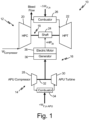
- FIG. 1 is a schematic diagram of a gas turbine engine power assist system 10, which includes primary engine 12 and secondary engine 14.
- Primary and secondary engines 12 and 14 are gas turbine engines.
- Primary engine 12 can be an aircraft propulsion engine, and secondary engine 14 can be an aircraft APU.
- Primary engine 12 and secondary engine 14 are interconnected by power linkage 16 through which power can be transferred between primary engine 12 and secondary engine 14.
- Primary engine 12 can be a multi-spool engine, having at least a low pressure spool and high pressure spool as known in the art. For simplicity, only high pressure spool 18 is illustrated. High pressure spool 18 includes high pressure compressor (HPC) 20 and high pressure turbine (HPT) 22 mounted on shaft 24. Although not illustrated, it will be understood by one of ordinary skill in the art that the low pressure spool can carry a fan, low pressure compressor, and low pressure turbine.
- Primary engine 12 is a Brayton cycle engine wherein a mixture of fuel and compressed air from HPC 20 is ignited in combustor 26 to drive rotation of HPT 22 and thereby HPC 20 via shaft 24.
- secondary engine 14 can be a gas turbine engine. As illustrated, secondary engine 14 includes compressor 28 and turbine 30 mounted on shaft 32. A mixture of fuel and compressed air from compressor 28 is ignited in combustor 34 to drive turbine 30 and thereby compressor 28 via shaft 32. Secondary engine 14 can additionally include a power turbine (not shown) mounted on a power shaft, which is rotationally independent from shaft 32. Secondary engine 14 can provide power for a range of peripheral aircraft functions independent from propulsion or from the operation of primary engine 12. For example, secondary engine 14 can be used for power generation, for cabin air circulation, and/or to drive mechanical actuation of aircraft components. Secondary engine 14 can have a number of configurations or cycles (e.g., wankel cycle) and is not limited to the gas turbine engine depicted.
- wankel cycle e.g., wankel cycle
- Primary engine 12 and secondary engine 14 are connected by power linkage 16, which includes generator 36 and motor 38.
- power linkage 16 When primary engine 12 is operating in an idle mode, fuel flow to primary engine 12 can be reduced and power extracted from secondary engine 14 can be provided to primary engine 12 via power linkage 16 to boost high pressure spool 18.
- an idle mode of operation refers to a rotational speed of the high spool 18 that is greater than the minimum rotational speed required to achieve starting of the engine and is less than the rotational speed (N2) associated with the maximum idle thrust of primary engine 12 set by the airframer. Idle is based on the engine's minimum limiting factor (e.g., minimum N1, N2, fuel air ratio, ECS bleed, etc.).
- Power assist system 10 can be used to supplement power to primary engine 12 during descent of the aircraft as well as during ground idle and other flight idle operations. As illustrated, rotational energy of shaft 32 of secondary engine 14 is transferred to shaft 24 on high pressure spool 18 of primary engine 12 via generator 36 and motor 38.
- Generator 36 and motor 38 can be a combined motor-generator capable of operating in a reverse direction (i.e., transferring power from primary engine 12 to secondary engine 14).
- Generator 36 and motor 38 can be separate components coupled via an electrical connection (not shown).
- Generator 36 is a rotary generator driven by shaft 32 to produce electrical power, which is provided to motor 38.
- Motor 38 uses the electrical power to drive shaft 24 of high pressure spool 18.
- the power shaft (not shown) of secondary engine 14 can be used to boost high pressure spool 18 of primary engine 12 via generator 36 and motor 38.
- fuel flow into combustor 26 of primary engine 12 is reduced, as indicated by - ⁇ W F, in , which represents a change in fuel flow from a conventional idle mode (i.e., idle without power assist).
- Fuel flow input (+W F, in APU ) to secondary engine 14 is required to operate secondary engine 14.
- Secondary engine 14 provides supplementary horsepower (+HP in ) to primary engine 12 via generator 36/motor 38. Supplemental power provided to primary engine 12 can cause high pressure spool 18 to rotate at a higher speed than a conventional idle speed.
- the increased speed of high pressure spool 18 can improve operation safety (i.e., improve compressor 20 operating stability margin) of primary engine 12 and response time from idle, allowing for a faster spool up time (time required to accelerate and increase fuel flow rate) if additional thrust output by engine 12 becomes necessary.
- operation safety i.e., improve compressor 20 operating stability margin
- response time from idle allowing for a faster spool up time (time required to accelerate and increase fuel flow rate) if additional thrust output by engine 12 becomes necessary.
- fuel flow in secondary engine 14 is increased, a net fuel reduction can be achieved, as is discussed further with respect to FIGS. 4-6 .
- the architecture of power linkage 16 can be used in reverse for boosting power to secondary engine 14.
- APU secondary engine 14
- power can be transferred from primary engine 12 to APU 14 when primary engine 12 is operating at high power.
- power assist system 10 is operated in reverse with high pressure spool 18 on primary engine 12 driving a combined motor-generator.
- Generator 36 provides electric power to motor 38, which in turn drives shaft 32 of APU 14.
- Such power transfer can reduce the idle fuel burn of APU 14, such that APU 14 can remain on during flight and ready to respond on demand while reducing fuel usage, or keep APU 14 spooled up to reduce reaction time at start-up.
- Boosting power to secondary engine 14 can be supplied by the low spool of primary engine 12 through separate power linkage (not shown).
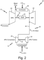
- FIG. 2 is a schematic diagram of an embodiment of a gas turbine engine power assist system 40 in which secondary gas turbine engine 14 provides compressed air to primary gas turbine engine 12.
- Power assist system 40 is identical to power assist system 10 with the exception of the power linkage.
- Power assist system 40 replaces electrical/mechanical linkage 16 with a mechanical power linkage 42.
- Power linkage 42 includes bleed air conduit 44, which connects compressor 28 of secondary engine 14 to HPT 22 of primary engine 10. Compressed bleed air from compressor 28 is provided directly into HPT 22 to provide torque to high pressure spool 18 and thereby boost power to primary engine 12 to maintain pressurization and operation at a reduced fuel flow (- ⁇ W F, in ).
- FIG. 3 is an alternative embodiment of a gas turbine engine power assist system 50 in which secondary gas turbine engine 14 supplements power to primary gas turbine engine 12 by providing compressed air to HPT 22 and by driving shaft 18 via generator 36 and motor 38.
- Power assist system 50 is identical to power assist systems 10 and 40 with the exception of the power linkage.
- Power assist system 50 includes power linkage 52, which is a combination of power linkage 16 and power linkage 42.
- Power linkage 52 can simultaneously deliver compressed air to HPT 22 to provide high spool torque while also driving shaft 18 via generator 36/motor 38. Additional benefit may be realized by combining the supplemental power provided by compressed air with rotational power provided by generator 36/motor 38 in some operations.
- Both power linkages influence the operating line on HPC 20. While the addition of compressed air into HPT 22 can have an adverse impact on the operating line, the rotational energy provided by motor 38 can have a positive impact on the operating line. Therefore, a balance between the two may provide a more efficient power boost to primary engine 12.
- FIGS. 4-6 provide graphical representations of fuel flow reduction using power assist systems 10, 40, and/or 50.
- FIG. 4 illustrates the effect of supplementing power to primary engine 12 using any of the power assist systems 10, 40, or 50.
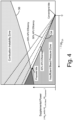
- FIG. 4 shows ability to reduce fuel flow to primary engine 12 as compared to fuel flow at conventional idle (- ⁇ W F, in ) by increasing horsepower (+HP in ) provided by secondary engine 14 via generator 36/motor 38 and/or increasing high spool torque provided by secondary engine 14 via compressed air from compressor 28 (shown as ratio of bleed air from compressor 28 to airflow entering compressor 20, W in, APU Bleed / W Compressor ).
- the conventional gas turbine idle point is the nominal fuel flow a gas turbine would operate at without boosting from secondary engine 14.
- FIG. 4 is a graphical representation of fuel flow reduction to the primary gas turbine engine with power boost to the primary gas turbine engine provided by the secondary gas turbine engine.
- FIG. 4 illustrates a conventional gas turbine engine idle point, in which the core supplies pressurized bleed air for the aircraft ECS (e.g., passenger cabin air).
- ECS e.g., passenger cabin air
- supplemental power must be provided to maintain minimum bleed air pressurization, identified by line 54.
- Insufficient supplemental power i.e., anything below line 54 falls within an Insufficient Bleed Pressure Zone for the aircraft ECS.
- supplemental power provided to primary engine 12 relative to fuel flow into primary engine 12 must fall below a lean blowout (LBO) limit or a Combustion Instability Zone, identified by line 56.
- LBO lean blowout
- Excessive supplemental power i.e., anything above line 56, falls within the Combustion Instability Zone in which a fuel-to-air ratio is reduced enough to cause the combustor flame to become unstable or extinguished.
- excessive supplemental power combined with excessive reduction in primary engine 12 fuel flow (- ⁇ W F, in ) can reduce combustor 26 fuel-to-air ratio below sustainable combustion.
- the proposed idle location using power assist systems 10, 40, 50 can lie near the intersection of combustion instability zone line 56 and the minimum bleed air pressurization line 54, preferably providing a safety margin between the proposed idle location and line 56.
- the proposed idle location is preferably on or near the minimum bleed air pressurization line 54 to avoid using fuel and supplemental power to pressurize air above what is required.
- the relationship between fuel flow and supplemental power provided to primary gas turbine engine 12 will vary for each power assist system 10, 40, 50.
- the graph of FIG. 4 is intended to provide a simplified example of the power assist used during a descent idle mode as disclosed herein. It will be understood by one of ordinary skill in the art that modeling will be required for each power assist system 10, 40, 50, which can include variations in primary and secondary engines 12, 14 and power linkages 16, 42, 52, to identify an ideal fuel/supplemental power input combination. Furthermore, it will be understood that models will look different depending on the mode of operation (i.e., flight idle or ground idle).
- power assist system 10, 40, 50 may be used to boost spool speed or reduce acceleration time without producing a net fuel flow reduction.
- vanes of HPC 20 may be used to restrict airflow to shift Combustion Instability Zone line 56.
- the incidence angles of the HPC vanes can be changed to allow more or less airflow depending on the speed of high pressure spool 18. As the vanes are closed, airflow from HPC 20 can be reduced, which allows for an additional reduction in primary engine 12 fuel flow before reaching the LBO limit. By restricting airflow from HPC 20, the fuel-to-air ratio can be adjusted to optimize operation of power assist systems 10, 40, 50.
- FIG. 4 includes varying APU 14 efficiency lines. As will be discussed further with respect to FIG. 6 , net fuel savings are dependent in part on the fuel efficiency at which APU 14 operates. Along the APU efficiency line, power assist systems 10, 40, and 50 are energy neutral (i.e., the amount fuel (+ ⁇ W F, in APU ) needed to generate supplemental power is balanced by the amount by fuel reduction (- ⁇ W F, in ) to primary engine 12). Net fuel savings are only achieved to the left of each APU efficiency line, with greater fuel savings realized the farther left the idle position is located from the APU efficiency line. As illustrated in FIG. 4 , the proposed idle location would result in a slight net fuel savings with supplemental power provided by secondary engine 14 operating at 40% efficiency, and improved net fuel savings with secondary engines 14 operating at 50% and 60% efficiency.
- FIG. 5 is a graphical representation of improved fuel reduction obtainable when aircraft ECS requirements of primary engine 12 are removed.
- pressurized air for the aircraft ECS can be supplied by a source of airflow other than the core or primary engine 12. Therefore, there is no requirement for primary engine 12 to supply pressurized bleed air for the aircraft ECS.
- the idle location can be moved further to the left in fuel flow to a new proposed idle operation as there is no requirement to meet a minimum bleed air pressurization.
- Supplemental power provided to primary engine 12 relative to fuel flow into primary engine 12 must fall below the Combustion Instability Zone line 56, and sufficient supplemental power (e.g., +HP in ) is still provided by secondary engine 14 to maintain an ideal idle speed as necessary to reduce the time primary engine 12 takes to spool up if additional thrust is needed.
- sufficient supplemental power e.g., +HP in
- FIG. 6 is a graphical representation of an example of net fuel reduction with power supplementation to the primary gas turbine engine during descent of the aircraft, accounting for secondary engine 14 fuel needed to generate supplemental power and primary engine 12 fuel.
- FIG. 6 represents model results for power assist system 10 for particular models of a turbofan engine 12 and APU 14.
- a power input of SP 1 would require a fuel reduction of approximately WF 1-2 (reduction from WF 1 to WF 2 ) fuel flow to primary engine 12 to be energy neutral, as indicated by the 50% APU energy efficiency.
- the reduction of WF 1-2 accounts for the amount of fuel needed by APU 14 to produce supplemental power for primary engine 12.
- any further reduction of fuel flow to primary engine 12 results in a net fuel savings of WF 2-3 (reduction from WF 2 to WF 3 ) as indicated in FIG. 6 .
- This is a reduction of about five percent in net fuel consumption, with a reduction of fuel flow to primary engine 12 of greater than ten percent over a conventional idle mode in which power to primary engine 12 is not boosted by secondary engine 14.
- the net fuel savings is dependent on the efficiency of APU 14 with lower APU efficiencies resulting in lower net fuel savings.
- net fuel flow may be unchanged or even increased depending on the system configuration and goal of operation.
- the primary goal of using power assist systems 10, 40, and 50 can be to improve readiness or response time of primary engine 12 in the event that additional thrust output is necessary. While use of power assist systems 10, 40, and 50 as disclosed can result in a net reduction in fuel flow, in some embodiments, power assist systems 10, 40, 50 may be used to boost spool speed or reduce acceleration time without producing a reduction in net fuel flow.
- a method of improving response time of primary engine 12 can include increasing supplementary horsepower (+HP in ) to primary engine 12 via power linkage 16 and reducing a bleed flow ratio of bleed air from compressor 28 to airflow entering compressor 20, W in, APU Bleed / W Compressor via power linkage 42 in a controlled time variant manner concurrent with an increase in combustor 26 fuel flow (+ ⁇ W F, in ) in primary engine 12.
- Power assist systems 10, 40, and 50 provide the capability for reducing fuel requirements of primary engine 12 during an idle mode of operation, and particularly, during descent of the aircraft.
- a net fuel savings can be realized by supplementing power to high pressure spool 18 via generator 36/motor 38 driven by secondary engine 14 and/or compressed bleed air from secondary engine compressor 28.
- supplemental power provided to primary engine 12 can increase the idle speed above the conventional idle speed providing safer engine operating conditions (i.e., improved compressor 20 operating stability margin) and reduced spool up time should additional thrust output by primary engine 12 be necessary.
- Power assist system 10 provides the additional benefit of being capable of operating in reverse, transferring power from primary engine 12 to secondary engine 14 to improve secondary engine 14 efficiency, such that the secondary engine 14 can remain on during flight and available for service as needed.
Landscapes
- Engineering & Computer Science (AREA)
- Mechanical Engineering (AREA)
- General Engineering & Computer Science (AREA)
- Chemical & Material Sciences (AREA)
- Combustion & Propulsion (AREA)
- Aviation & Aerospace Engineering (AREA)
- Power Engineering (AREA)
- Transportation (AREA)
- Engine Equipment That Uses Special Cycles (AREA)
- Control Of Turbines (AREA)
Description
- The present disclosure relates generally to multiple engine gas turbine systems, and more particularly to a power-assist system in which power is transferred between an auxiliary power unit (APU) and a high spool of a primary engine.
- Conventional aircraft turbine engines remain on during descent and idle to provide pressurized cabin air and avoid the need for in-flight restart. The idle mode requires fuel burn sufficient to ensure a self-sustaining engine. A need exists to reduce the amount of fuel needed during idle to improve engine economics.
-
EP2452876A2 discloses a prior art aircraft hybrid gas turbofan according to the preamble of claim 4. - A.V. Lukovnikov et al: "The Hybrid Propulsion Systems for the Advanced Aircraft", 7 December 2014, pages 1-5, XP055675057, and
EP1728990A2 disclose other aircraft hybrid gas turbofan prior art systems. - In an aspect, a method of operating an aircraft hybrid gas turbofan is provided as set forth in
claim 1. - In another aspect, an aircraft hybrid gas turbofan is provided as set forth in claim 4.
- Features of embodiments of the invention are set forth in the dependent claims.
- The present summary is provided only by way of example, and not limitation. Other aspects of the present disclosure will be appreciated in view of the entirety of the present disclosure, including the entire text, claims, and accompanying figures.
-
-
FIG. 1 is a schematic diagram of a gas turbine engine power assist system in which a secondary gas turbine engine boosts power to a primary gas turbine engine of an aircraft through a power linkage including a generator and motor. -
FIG. 2 is a schematic diagram of an embodiment of a gas turbine engine power assist system in which the secondary gas turbine engine boosts power to the primary gas turbine engine through a power linkage, which provides compressed air from the secondary gas turbine engine to a high pressure turbine of the primary gas turbine engine. -
FIG. 3 is another embodiment of a gas turbine engine power assist system in which the secondary gas turbine engine boosts power to the primary gas turbine engine through the power linkages ofFIGS. 1 and2 . -
FIG. 4 is a graphical representation of fuel flow reduction to the primary gas turbine engine with power boost to the primary gas turbine engine provided by the secondary gas turbine engine. -
FIG. 5 is a graphical representation of improved fuel flow reduction overFIG. 4 obtainable when environmental control system requirements of the primary gas turbine engine are removed. -
FIG. 6 is a graphical representation of net fuel reduction with power supplementation to the primary gas turbine engine, accounting for fuel needed to generate supplemental power. - While the above-identified figures set forth one or more embodiments of the present disclosure, other embodiments are also contemplated, as noted in the discussion. In all cases, this disclosure presents the invention by way of representation and not limitation. It should be understood that numerous other modifications and embodiments can be devised by those skilled in the art, which fall within the scope of the invention. The figures may not be drawn to scale, and applications and embodiments of the present invention may include features and components not specifically shown in the drawings.
- The present disclosure provides several modes of providing power assist to a high spool of a primary gas turbine engine to enable a reduced fuel flow during an idle mode of operation, and particularly, during descent of an aircraft. Primary gas turbine engines on an aircraft are kept on during descent to maintain minimum air pressurization needed for an aircraft environmental control system (ECS) and to remain available for operation if needed. Significant fuel flow inputs are necessary to keep an engine on during descent. The engine can remain on with minimum pressurization maintained at a reduced fuel flow if the power to the engine is supplemented. The present disclosure is directed to operation of an aircraft hybrid gas turbofan in which a secondary gas turbine engine, such as an auxiliary power unit (APU), is used to provide supplemental power to the primary gas turbine engine to provide a sub-idle descent mode of operation. In one mode, the APU drives a generator, which supplies electrical energy to a motor used to boost power to the high spool of the primary engine. In another mode, the APU provides compressed air into a turbine section of the primary engine to provide high spool torque. In yet another mode, the APU provides both electric power to boost the high spool and compressed air to the turbine section to increase high spool torque. While fuel input is required to power the APU, each power assist mode can result in a net fuel savings. Additionally, the same architecture provided for supplementing power to the primary engine via generator/motor can be used in reverse for supplementing power to the APU. When the primary engine is operating at high power, the power transfer can be reversed, with the high spool (or low spool) on the primary engine boosting a shaft of the APU via a generator and motor. Such power transfer can improve APU efficiency, such that the APU can remain on or spooled up during flight and available for service on demand.
-
FIG. 1 is a schematic diagram of a gas turbine enginepower assist system 10, which includesprimary engine 12 andsecondary engine 14. Primary andsecondary engines Primary engine 12 can be an aircraft propulsion engine, andsecondary engine 14 can be an aircraft APU.Primary engine 12 andsecondary engine 14 are interconnected bypower linkage 16 through which power can be transferred betweenprimary engine 12 andsecondary engine 14. -
Primary engine 12 can be a multi-spool engine, having at least a low pressure spool and high pressure spool as known in the art. For simplicity, onlyhigh pressure spool 18 is illustrated.High pressure spool 18 includes high pressure compressor (HPC) 20 and high pressure turbine (HPT) 22 mounted onshaft 24. Although not illustrated, it will be understood by one of ordinary skill in the art that the low pressure spool can carry a fan, low pressure compressor, and low pressure turbine.Primary engine 12 is a Brayton cycle engine wherein a mixture of fuel and compressed air from HPC 20 is ignited incombustor 26 to drive rotation of HPT 22 and thereby HPC 20 viashaft 24. - Like
primary engine 12,secondary engine 14 can be a gas turbine engine. As illustrated,secondary engine 14 includescompressor 28 andturbine 30 mounted onshaft 32. A mixture of fuel and compressed air fromcompressor 28 is ignited incombustor 34 to driveturbine 30 and therebycompressor 28 viashaft 32.Secondary engine 14 can additionally include a power turbine (not shown) mounted on a power shaft, which is rotationally independent fromshaft 32.Secondary engine 14 can provide power for a range of peripheral aircraft functions independent from propulsion or from the operation ofprimary engine 12. For example,secondary engine 14 can be used for power generation, for cabin air circulation, and/or to drive mechanical actuation of aircraft components.Secondary engine 14 can have a number of configurations or cycles (e.g., wankel cycle) and is not limited to the gas turbine engine depicted. -
Primary engine 12 andsecondary engine 14 are connected bypower linkage 16, which includesgenerator 36 andmotor 38. Whenprimary engine 12 is operating in an idle mode, fuel flow toprimary engine 12 can be reduced and power extracted fromsecondary engine 14 can be provided toprimary engine 12 viapower linkage 16 to boosthigh pressure spool 18. As used herein, an idle mode of operation refers to a rotational speed of thehigh spool 18 that is greater than the minimum rotational speed required to achieve starting of the engine and is less than the rotational speed (N2) associated with the maximum idle thrust ofprimary engine 12 set by the airframer. Idle is based on the engine's minimum limiting factor (e.g., minimum N1, N2, fuel air ratio, ECS bleed, etc.).Power assist system 10 can be used to supplement power toprimary engine 12 during descent of the aircraft as well as during ground idle and other flight idle operations. As illustrated, rotational energy ofshaft 32 ofsecondary engine 14 is transferred toshaft 24 onhigh pressure spool 18 ofprimary engine 12 viagenerator 36 andmotor 38.Generator 36 andmotor 38 can be a combined motor-generator capable of operating in a reverse direction (i.e., transferring power fromprimary engine 12 to secondary engine 14).Generator 36 andmotor 38 can be separate components coupled via an electrical connection (not shown).Generator 36 is a rotary generator driven byshaft 32 to produce electrical power, which is provided tomotor 38.Motor 38, in turn, uses the electrical power to driveshaft 24 ofhigh pressure spool 18. The power shaft (not shown) ofsecondary engine 14 can be used to boosthigh pressure spool 18 ofprimary engine 12 viagenerator 36 andmotor 38. - As illustrated, during operation of
power assist system 10, fuel flow intocombustor 26 ofprimary engine 12 is reduced, as indicated by -ΔWF, in, which represents a change in fuel flow from a conventional idle mode (i.e., idle without power assist). Fuel flow input (+WF, in APU) tosecondary engine 14 is required to operatesecondary engine 14.Secondary engine 14 provides supplementary horsepower (+HPin) toprimary engine 12 viagenerator 36/motor 38. Supplemental power provided toprimary engine 12 can causehigh pressure spool 18 to rotate at a higher speed than a conventional idle speed. The increased speed ofhigh pressure spool 18 can improve operation safety (i.e., improvecompressor 20 operating stability margin) ofprimary engine 12 and response time from idle, allowing for a faster spool up time (time required to accelerate and increase fuel flow rate) if additional thrust output byengine 12 becomes necessary. Although fuel flow insecondary engine 14 is increased, a net fuel reduction can be achieved, as is discussed further with respect toFIGS. 4-6 . - The architecture of
power linkage 16 can be used in reverse for boosting power tosecondary engine 14. In some operations, it may be beneficial to have a hybrid electric configuration in which an APU (secondary engine 14) is available on an as-needed basis throughout an entire flight. As such, it may be desired to runAPU 14 at idle during the entire flight or keepAPU 14 spooled up, but off, to ensureAPU 14 is ready when needed. To reduce the amount of fuel needed to runAPU 14 at idle or to keepAPU 14 spooled up, power can be transferred fromprimary engine 12 toAPU 14 whenprimary engine 12 is operating at high power. In this configuration,power assist system 10 is operated in reverse withhigh pressure spool 18 onprimary engine 12 driving a combined motor-generator.Generator 36 provides electric power tomotor 38, which in turn drivesshaft 32 ofAPU 14. Such power transfer can reduce the idle fuel burn ofAPU 14, such thatAPU 14 can remain on during flight and ready to respond on demand while reducing fuel usage, or keepAPU 14 spooled up to reduce reaction time at start-up. Boosting power tosecondary engine 14 can be supplied by the low spool ofprimary engine 12 through separate power linkage (not shown). -
FIG. 2 is a schematic diagram of an embodiment of a gas turbine enginepower assist system 40 in which secondarygas turbine engine 14 provides compressed air to primarygas turbine engine 12. Power assistsystem 40 is identical to power assistsystem 10 with the exception of the power linkage. Power assistsystem 40 replaces electrical/mechanical linkage 16 with amechanical power linkage 42.Power linkage 42 includesbleed air conduit 44, which connectscompressor 28 ofsecondary engine 14 toHPT 22 ofprimary engine 10. Compressed bleed air fromcompressor 28 is provided directly intoHPT 22 to provide torque tohigh pressure spool 18 and thereby boost power toprimary engine 12 to maintain pressurization and operation at a reduced fuel flow (-ΔWF, in). Although fuel input (+WF, in APU) is required to operatesecondary engine 14, a net fuel savings can still be realized usingpower assist system 40. In addition, the capability for bleeding off compressor air fromsecondary engine 14 could facilitate operation ofsecondary engine 14 in certain operating conditions, as such architecture allows for rematching each participatingengine cycle compressor 28 shown, which could alternatively provide a source of bleed air. As previously discussed,secondary engine 14 is not limited to the embodiment shown. It will be understood by one of ordinary skill in the art that the source of bleed air can vary depending on the configuration of the APU. -
FIG. 3 is an alternative embodiment of a gas turbine enginepower assist system 50 in which secondarygas turbine engine 14 supplements power to primarygas turbine engine 12 by providing compressed air toHPT 22 and by drivingshaft 18 viagenerator 36 andmotor 38. Power assistsystem 50 is identical to power assistsystems system 50 includespower linkage 52, which is a combination ofpower linkage 16 andpower linkage 42.Power linkage 52 can simultaneously deliver compressed air toHPT 22 to provide high spool torque while also drivingshaft 18 viagenerator 36/motor 38. Additional benefit may be realized by combining the supplemental power provided by compressed air with rotational power provided bygenerator 36/motor 38 in some operations. Both power linkages influence the operating line onHPC 20. While the addition of compressed air intoHPT 22 can have an adverse impact on the operating line, the rotational energy provided bymotor 38 can have a positive impact on the operating line. Therefore, a balance between the two may provide a more efficient power boost toprimary engine 12. -
FIGS. 4-6 provide graphical representations of fuel flow reduction usingpower assist systems FIG. 4 illustrates the effect of supplementing power toprimary engine 12 using any of thepower assist systems FIG. 4 shows ability to reduce fuel flow toprimary engine 12 as compared to fuel flow at conventional idle (-ΔWF, in) by increasing horsepower (+HPin) provided bysecondary engine 14 viagenerator 36/motor 38 and/or increasing high spool torque provided bysecondary engine 14 via compressed air from compressor 28 (shown as ratio of bleed air fromcompressor 28 to airflow enteringcompressor 20, Win, APU Bleed / WCompressor). The conventional gas turbine idle point is the nominal fuel flow a gas turbine would operate at without boosting fromsecondary engine 14. -
FIG. 4 is a graphical representation of fuel flow reduction to the primary gas turbine engine with power boost to the primary gas turbine engine provided by the secondary gas turbine engine.FIG. 4 illustrates a conventional gas turbine engine idle point, in which the core supplies pressurized bleed air for the aircraft ECS (e.g., passenger cabin air). As fuel flow toprimary engine 12 is reduced, supplemental power must be provided to maintain minimum bleed air pressurization, identified byline 54. Insufficient supplemental power, i.e., anything belowline 54 falls within an Insufficient Bleed Pressure Zone for the aircraft ECS. Additionally, supplemental power provided toprimary engine 12 relative to fuel flow intoprimary engine 12 must fall below a lean blowout (LBO) limit or a Combustion Instability Zone, identified byline 56. Excessive supplemental power, i.e., anything aboveline 56, falls within the Combustion Instability Zone in which a fuel-to-air ratio is reduced enough to cause the combustor flame to become unstable or extinguished. In other words, excessive supplemental power combined with excessive reduction inprimary engine 12 fuel flow (-ΔWF, in) can reducecombustor 26 fuel-to-air ratio below sustainable combustion. The proposed idle location usingpower assist systems instability zone line 56 and the minimum bleedair pressurization line 54, preferably providing a safety margin between the proposed idle location andline 56. In some embodiments, the proposed idle location is preferably on or near the minimum bleedair pressurization line 54 to avoid using fuel and supplemental power to pressurize air above what is required. - The relationship between fuel flow and supplemental power provided to primary
gas turbine engine 12 will vary for eachpower assist system FIG. 4 is intended to provide a simplified example of the power assist used during a descent idle mode as disclosed herein. It will be understood by one of ordinary skill in the art that modeling will be required for eachpower assist system secondary engines power linkages primary engine 12 in the event that additional thrust output is necessary. In some embodiments,power assist system - Additional configurations may be considered in optimization of
power assist systems HPC 20 may be used to restrict airflow to shift CombustionInstability Zone line 56. The incidence angles of the HPC vanes can be changed to allow more or less airflow depending on the speed ofhigh pressure spool 18. As the vanes are closed, airflow fromHPC 20 can be reduced, which allows for an additional reduction inprimary engine 12 fuel flow before reaching the LBO limit. By restricting airflow fromHPC 20, the fuel-to-air ratio can be adjusted to optimize operation ofpower assist systems - The efficiency of
secondary engine 14 can also significantly impact the potential for net fuel savings achieved bypower assist systems FIG. 4 includes varyingAPU 14 efficiency lines. As will be discussed further with respect toFIG. 6 , net fuel savings are dependent in part on the fuel efficiency at whichAPU 14 operates. Along the APU efficiency line,power assist systems FIG. 4 , the proposed idle location would result in a slight net fuel savings with supplemental power provided bysecondary engine 14 operating at 40% efficiency, and improved net fuel savings withsecondary engines 14 operating at 50% and 60% efficiency. -
FIG. 5 is a graphical representation of improved fuel reduction obtainable when aircraft ECS requirements ofprimary engine 12 are removed. In some embodiments, pressurized air for the aircraft ECS can be supplied by a source of airflow other than the core orprimary engine 12. Therefore, there is no requirement forprimary engine 12 to supply pressurized bleed air for the aircraft ECS. In such embodiments, the idle location can be moved further to the left in fuel flow to a new proposed idle operation as there is no requirement to meet a minimum bleed air pressurization. Supplemental power provided toprimary engine 12 relative to fuel flow intoprimary engine 12 must fall below the CombustionInstability Zone line 56, and sufficient supplemental power (e.g., +HPin) is still provided bysecondary engine 14 to maintain an ideal idle speed as necessary to reduce the timeprimary engine 12 takes to spool up if additional thrust is needed. -
FIG. 6 is a graphical representation of an example of net fuel reduction with power supplementation to the primary gas turbine engine during descent of the aircraft, accounting forsecondary engine 14 fuel needed to generate supplemental power andprimary engine 12 fuel.FIG. 6 represents model results forpower assist system 10 for particular models of aturbofan engine 12 andAPU 14. As illustrated inFIG. 6 , forAPU 14 operating at 50% efficiency a power input of SP1 would require a fuel reduction of approximately WF1-2 (reduction from WF1 to WF2) fuel flow toprimary engine 12 to be energy neutral, as indicated by the 50% APU energy efficiency. The reduction of WF1-2 accounts for the amount of fuel needed byAPU 14 to produce supplemental power forprimary engine 12. Any further reduction of fuel flow toprimary engine 12 results in a net fuel savings of WF2-3 (reduction from WF2 to WF3) as indicated inFIG. 6 . This is a reduction of about five percent in net fuel consumption, with a reduction of fuel flow toprimary engine 12 of greater than ten percent over a conventional idle mode in which power toprimary engine 12 is not boosted bysecondary engine 14. As previously discussed, the net fuel savings is dependent on the efficiency ofAPU 14 with lower APU efficiencies resulting in lower net fuel savings. - In some embodiments, net fuel flow may be unchanged or even increased depending on the system configuration and goal of operation. The primary goal of using
power assist systems primary engine 12 in the event that additional thrust output is necessary. While use ofpower assist systems power assist systems power assist system 50, a method of improving response time ofprimary engine 12 can include increasing supplementary horsepower (+HPin) toprimary engine 12 viapower linkage 16 and reducing a bleed flow ratio of bleed air fromcompressor 28 to airflow enteringcompressor 20, Win, APU Bleed / WCompressor viapower linkage 42 in a controlled time variant manner concurrent with an increase incombustor 26 fuel flow (+ΔWF, in) inprimary engine 12. - Power assist
systems primary engine 12 during an idle mode of operation, and particularly, during descent of the aircraft. A net fuel savings can be realized by supplementing power tohigh pressure spool 18 viagenerator 36/motor 38 driven bysecondary engine 14 and/or compressed bleed air fromsecondary engine compressor 28. In addition, supplemental power provided toprimary engine 12 can increase the idle speed above the conventional idle speed providing safer engine operating conditions (i.e.,improved compressor 20 operating stability margin) and reduced spool up time should additional thrust output byprimary engine 12 be necessary. Power assistsystem 10 provides the additional benefit of being capable of operating in reverse, transferring power fromprimary engine 12 tosecondary engine 14 to improvesecondary engine 14 efficiency, such that thesecondary engine 14 can remain on during flight and available for service as needed. - While the invention has been described with reference to an exemplary embodiment(s), it will be understood by those skilled in the art that various changes may be made without departing from the scope of the invention. Therefore, it is intended that the invention not be limited to the particular embodiment(s) disclosed, but that the invention will include all embodiments falling within the scope of the appended claims.
Claims (5)
- A method of operating an aircraft hybrid gas turbofan, the method comprising:providing supplemental power to a primary gas turbine engine (12) during a mode of operation of the primary gas turbine engine (12), wherein providing supplemental power comprises boosting the high spool (18) of the primary gas turbine engine (12) using a secondary gas turbine engine (14) via a first power linkage (42; 52) connecting the primary and secondary gas turbine engines (12, 14), and wherein the primary gas turbine engine (12) is a propulsion engine and the secondary gas turbine engine (14) is an auxiliary power unit (APU);characterised in that:providing supplemental power to the primary gas turbine engine (12) occurs during descent of the aircraft;the method further comprises reducing a fuel flow to the primary gas turbine engine (12) when supplemental power is provided to the primary gas turbine engine (12) by the APU; andboosting the high spool (18) of the primary gas turbine engine (12) comprises a first power supplementation method, wherein the first power supplementation method comprises:generating compressed air in the secondary gas turbine engine (14); andproviding the compressed air directly into a turbine (22) of the high spool (18) of the primary gas turbine engine (12) to provide high spool torque.
- The method of claim 1, wherein boosting the high spool (18) of the primary gas turbine engine (12) comprises a second power supplementation method;
wherein the second power supplementation method comprises:driving a generator (36) with the secondary gas turbine engine (14);coupling a motor (38) to the high spool (18); andpowering the motor (38) via the generator (36). - The method of claim 1 or 2, wherein boosting the high spool (18) of the primary gas turbine engine (12) comprises providing supplemental power to the primary gas turbine engine (12) in an amount greater than 100 horsepower.
- An aircraft hybrid gas turbofan, comprising:a primary gas turbine engine (12) having a high spool (18), wherein the primary gas turbine engine (12) is a propulsion engine;a secondary gas turbine engine (14), wherein the secondary gas turbine engine (14) is an auxiliary power unit (APU); anda power linkage (42; 52) between the high spool (18) of the primary gas turbine engine (12) and the APU;characterised in that:
the power linkage (42; 52) includes a mechanical coupling comprising a bleed air conduit (44) connecting a compressor section of the APU to a core gas path of a turbine (22) of the high spool (18). - The aircraft hybrid gas turbofan of claim 4, wherein the power linkage (52) includes a combined motor/generator (36; 38) configured to transfer power between the high spool (18) of the primary gas turbine engine (12) and the APU.
Applications Claiming Priority (1)
| Application Number | Priority Date | Filing Date | Title |
|---|---|---|---|
| US201862719375P | 2018-08-17 | 2018-08-17 |
Publications (2)
| Publication Number | Publication Date |
|---|---|
| EP3640450A1 EP3640450A1 (en) | 2020-04-22 |
| EP3640450B1 true EP3640450B1 (en) | 2024-04-17 |
Family
ID=67658636
Family Applications (1)
| Application Number | Title | Priority Date | Filing Date |
|---|---|---|---|
| EP19191061.1A Active EP3640450B1 (en) | 2018-08-17 | 2019-08-09 | A method of operating an aircraft hybrid gas turbofan and relative hybrid gas turbofan |
Country Status (2)
| Country | Link |
|---|---|
| US (1) | US20200056497A1 (en) |
| EP (1) | EP3640450B1 (en) |
Families Citing this family (18)
| Publication number | Priority date | Publication date | Assignee | Title |
|---|---|---|---|---|
| US11035300B2 (en) * | 2019-03-29 | 2021-06-15 | Rolls-Royce Corporation | Control of a gas turbine driving a generator of an electrical system based on faults detected in the electrical system |
| US10914234B1 (en) | 2019-08-23 | 2021-02-09 | Raytheon Technologies Corporation | Gas turbine engine and method for operating same |
| US20210310412A1 (en) * | 2020-04-06 | 2021-10-07 | Williams International Co., L.L.C. | External auxiliary power unit |
| US12291995B2 (en) * | 2021-10-29 | 2025-05-06 | Rtx Corporation | Hybrid electric single engine descent power extraction control |
| EP4173957A1 (en) * | 2021-10-29 | 2023-05-03 | Raytheon Technologies Corporation | Power management in a hybrid-electric propulsion system during single engine failure at descent |
| EP4174298B1 (en) | 2021-10-29 | 2024-08-28 | RTX Corporation | Hybrid-electric single engine descent engine management |
| US12258141B2 (en) | 2021-10-29 | 2025-03-25 | Rtx Corporation | Hybrid electric single engine descent energy management |
| US11867131B2 (en) * | 2021-10-29 | 2024-01-09 | Rtx Corporation | Hybrid electric single engine descent mode activation logic |
| US11898490B2 (en) | 2022-05-05 | 2024-02-13 | Rtx Corporation | Transmission and method for control of boost spool |
| US11976598B2 (en) * | 2022-05-05 | 2024-05-07 | Rtx Corporation | Transmission and method for control of boost spool |
| US11649763B1 (en) * | 2022-06-23 | 2023-05-16 | Raytheon Technologies Corporation | Rating control architecture and method for hybrid electric engine |
| US12385434B2 (en) | 2022-06-26 | 2025-08-12 | Rtx Corporation | Aircraft powerplant with boosted gas turbine engine |
| US12244209B2 (en) | 2023-06-08 | 2025-03-04 | Rtx Corporation | Aircraft powerplant with boosted gas turbine engine |
| US20240410321A1 (en) * | 2023-06-09 | 2024-12-12 | Pratt & Whitney Canada Corp. | System and method for controlling engines of a multi-engine aircraft engine assembly |
| US20240417092A1 (en) * | 2023-06-16 | 2024-12-19 | Pratt & Whitney Canada Corp. | System and method for controlling engines of a multi-engine aircraft engine assembly |
| US12110116B1 (en) | 2023-06-30 | 2024-10-08 | Rtx Corporation | Pre-heating aircraft engine in standby mode |
| US12270332B1 (en) * | 2023-09-26 | 2025-04-08 | Pratt & Whitney Canada Corp. | Hybrid-electric aircraft propulsion system control system and method |
| US12552545B1 (en) | 2025-03-03 | 2026-02-17 | Rtx Corporation | Drivetrain for aircraft powerplant with boosted turbine engine |
Citations (1)
| Publication number | Priority date | Publication date | Assignee | Title |
|---|---|---|---|---|
| US20170226934A1 (en) * | 2014-08-08 | 2017-08-10 | Safran Aircraft Engines | Hybridisation of the compressors of a turbojet |
Family Cites Families (2)
| Publication number | Priority date | Publication date | Assignee | Title |
|---|---|---|---|---|
| US7464533B2 (en) * | 2003-01-28 | 2008-12-16 | General Electric Company | Apparatus for operating gas turbine engines |
| US8684304B2 (en) * | 2010-11-16 | 2014-04-01 | Rolls-Royce Corporation | Aircraft, propulsion system, and system for taxiing an aircraft |
-
2019
- 2019-06-04 US US16/431,245 patent/US20200056497A1/en not_active Abandoned
- 2019-08-09 EP EP19191061.1A patent/EP3640450B1/en active Active
Patent Citations (1)
| Publication number | Priority date | Publication date | Assignee | Title |
|---|---|---|---|---|
| US20170226934A1 (en) * | 2014-08-08 | 2017-08-10 | Safran Aircraft Engines | Hybridisation of the compressors of a turbojet |
Also Published As
| Publication number | Publication date |
|---|---|
| US20200056497A1 (en) | 2020-02-20 |
| EP3640450A1 (en) | 2020-04-22 |
Similar Documents
| Publication | Publication Date | Title |
|---|---|---|
| EP3640450B1 (en) | A method of operating an aircraft hybrid gas turbofan and relative hybrid gas turbofan | |
| EP3551537B1 (en) | Aircraft and method for supplying engine air to an environmental control system | |
| US9328667B2 (en) | Systems and methods for changing a speed of a compressor boost stage in a gas turbine | |
| CA2902461C (en) | Hybrid turbo electric aero-propulsion system control | |
| JP5325367B2 (en) | Method and apparatus for operating a gas turbine engine | |
| EP3211183B1 (en) | Method and apparatus for controlling a compressor of a gas turbine engine | |
| US20200032702A1 (en) | Multi-engine architecture with linkages to multiple spools | |
| EP3315747B1 (en) | Fan module with rotatable vane ring power system | |
| EP2602458A2 (en) | Multiple turboshaft engine control method and system for helicopters | |
| US20100251726A1 (en) | Turbine engine transient power extraction system and method | |
| JP2006336652A (en) | Method and apparatus for operating a gas turbine engine | |
| EP3127816A1 (en) | Auxiliary power unit assembly and a method of using the same | |
| US12054268B2 (en) | Hybrid propulsion system including electric motor with fan shroud encircling integrated fan blades | |
| JP2006194247A (en) | Gas turbine engine assembly | |
| US9175605B2 (en) | Gas turbine engine surge margin bleed power recuperation | |
| US20210276725A1 (en) | Systems and Methods for Defining APU Steady State Speed according to the Aircraft Operational Conditions | |
| US11015476B2 (en) | Electrical energy generating system | |
| US11718408B2 (en) | Electric power system for powerplants of a multi-engine aircraft | |
| US12221221B2 (en) | Sub-idle hybrid operation mode for hybrid electric propulsion system | |
| US20250163823A1 (en) | Hybrid gas turbofan powered sub-idle descent mode | |
| CN115585067A (en) | Gas turbine engine and method of operation | |
| US11982239B2 (en) | Gas turbine engine system with mixed flow auxiliary power unit | |
| CA3072944A1 (en) | Electric power system for powerplants of a multi-engine aircraft |
Legal Events
| Date | Code | Title | Description |
|---|---|---|---|
| PUAI | Public reference made under article 153(3) epc to a published international application that has entered the european phase |
Free format text: ORIGINAL CODE: 0009012 |
|
| STAA | Information on the status of an ep patent application or granted ep patent |
Free format text: STATUS: THE APPLICATION HAS BEEN PUBLISHED |
|
| AK | Designated contracting states |
Kind code of ref document: A1 Designated state(s): AL AT BE BG CH CY CZ DE DK EE ES FI FR GB GR HR HU IE IS IT LI LT LU LV MC MK MT NL NO PL PT RO RS SE SI SK SM TR |
|
| AX | Request for extension of the european patent |
Extension state: BA ME |
|
| STAA | Information on the status of an ep patent application or granted ep patent |
Free format text: STATUS: REQUEST FOR EXAMINATION WAS MADE |
|
| 17P | Request for examination filed |
Effective date: 20201022 |
|
| RBV | Designated contracting states (corrected) |
Designated state(s): AL AT BE BG CH CY CZ DE DK EE ES FI FR GB GR HR HU IE IS IT LI LT LU LV MC MK MT NL NO PL PT RO RS SE SI SK SM TR |
|
| RAP1 | Party data changed (applicant data changed or rights of an application transferred) |
Owner name: RAYTHEON TECHNOLOGIES CORPORATION |
|
| STAA | Information on the status of an ep patent application or granted ep patent |
Free format text: STATUS: EXAMINATION IS IN PROGRESS |
|
| 17Q | First examination report despatched |
Effective date: 20210913 |
|
| RAP3 | Party data changed (applicant data changed or rights of an application transferred) |
Owner name: RTX CORPORATION |
|
| GRAP | Despatch of communication of intention to grant a patent |
Free format text: ORIGINAL CODE: EPIDOSNIGR1 |
|
| STAA | Information on the status of an ep patent application or granted ep patent |
Free format text: STATUS: GRANT OF PATENT IS INTENDED |
|
| INTG | Intention to grant announced |
Effective date: 20231110 |
|
| INTG | Intention to grant announced |
Effective date: 20231110 |
|
| GRAS | Grant fee paid |
Free format text: ORIGINAL CODE: EPIDOSNIGR3 |
|
| GRAA | (expected) grant |
Free format text: ORIGINAL CODE: 0009210 |
|
| STAA | Information on the status of an ep patent application or granted ep patent |
Free format text: STATUS: THE PATENT HAS BEEN GRANTED |
|
| AK | Designated contracting states |
Kind code of ref document: B1 Designated state(s): AL AT BE BG CH CY CZ DE DK EE ES FI FR GB GR HR HU IE IS IT LI LT LU LV MC MK MT NL NO PL PT RO RS SE SI SK SM TR |
|
| REG | Reference to a national code |
Ref country code: GB Ref legal event code: FG4D |
|
| REG | Reference to a national code |
Ref country code: CH Ref legal event code: EP |
|
| REG | Reference to a national code |
Ref country code: DE Ref legal event code: R096 Ref document number: 602019050335 Country of ref document: DE |
|
| REG | Reference to a national code |
Ref country code: IE Ref legal event code: FG4D |
|
| REG | Reference to a national code |
Ref country code: LT Ref legal event code: MG9D |
|
| REG | Reference to a national code |
Ref country code: NL Ref legal event code: MP Effective date: 20240417 |
|
| REG | Reference to a national code |
Ref country code: AT Ref legal event code: MK05 Ref document number: 1677450 Country of ref document: AT Kind code of ref document: T Effective date: 20240417 |
|
| PG25 | Lapsed in a contracting state [announced via postgrant information from national office to epo] |
Ref country code: NL Free format text: LAPSE BECAUSE OF FAILURE TO SUBMIT A TRANSLATION OF THE DESCRIPTION OR TO PAY THE FEE WITHIN THE PRESCRIBED TIME-LIMIT Effective date: 20240417 |
|
| PG25 | Lapsed in a contracting state [announced via postgrant information from national office to epo] |
Ref country code: NL Free format text: LAPSE BECAUSE OF FAILURE TO SUBMIT A TRANSLATION OF THE DESCRIPTION OR TO PAY THE FEE WITHIN THE PRESCRIBED TIME-LIMIT Effective date: 20240417 |
|
| PG25 | Lapsed in a contracting state [announced via postgrant information from national office to epo] |
Ref country code: IS Free format text: LAPSE BECAUSE OF FAILURE TO SUBMIT A TRANSLATION OF THE DESCRIPTION OR TO PAY THE FEE WITHIN THE PRESCRIBED TIME-LIMIT Effective date: 20240817 |
|
| PG25 | Lapsed in a contracting state [announced via postgrant information from national office to epo] |
Ref country code: BG Free format text: LAPSE BECAUSE OF FAILURE TO SUBMIT A TRANSLATION OF THE DESCRIPTION OR TO PAY THE FEE WITHIN THE PRESCRIBED TIME-LIMIT Effective date: 20240417 |
|
| PG25 | Lapsed in a contracting state [announced via postgrant information from national office to epo] |
Ref country code: HR Free format text: LAPSE BECAUSE OF FAILURE TO SUBMIT A TRANSLATION OF THE DESCRIPTION OR TO PAY THE FEE WITHIN THE PRESCRIBED TIME-LIMIT Effective date: 20240417 Ref country code: FI Free format text: LAPSE BECAUSE OF FAILURE TO SUBMIT A TRANSLATION OF THE DESCRIPTION OR TO PAY THE FEE WITHIN THE PRESCRIBED TIME-LIMIT Effective date: 20240417 |
|
| PG25 | Lapsed in a contracting state [announced via postgrant information from national office to epo] |
Ref country code: GR Free format text: LAPSE BECAUSE OF FAILURE TO SUBMIT A TRANSLATION OF THE DESCRIPTION OR TO PAY THE FEE WITHIN THE PRESCRIBED TIME-LIMIT Effective date: 20240718 |
|
| PG25 | Lapsed in a contracting state [announced via postgrant information from national office to epo] |
Ref country code: PT Free format text: LAPSE BECAUSE OF FAILURE TO SUBMIT A TRANSLATION OF THE DESCRIPTION OR TO PAY THE FEE WITHIN THE PRESCRIBED TIME-LIMIT Effective date: 20240819 |
|
| PG25 | Lapsed in a contracting state [announced via postgrant information from national office to epo] |
Ref country code: ES Free format text: LAPSE BECAUSE OF FAILURE TO SUBMIT A TRANSLATION OF THE DESCRIPTION OR TO PAY THE FEE WITHIN THE PRESCRIBED TIME-LIMIT Effective date: 20240417 |
|
| PG25 | Lapsed in a contracting state [announced via postgrant information from national office to epo] |
Ref country code: AT Free format text: LAPSE BECAUSE OF FAILURE TO SUBMIT A TRANSLATION OF THE DESCRIPTION OR TO PAY THE FEE WITHIN THE PRESCRIBED TIME-LIMIT Effective date: 20240417 |
|
| PG25 | Lapsed in a contracting state [announced via postgrant information from national office to epo] |
Ref country code: PL Free format text: LAPSE BECAUSE OF FAILURE TO SUBMIT A TRANSLATION OF THE DESCRIPTION OR TO PAY THE FEE WITHIN THE PRESCRIBED TIME-LIMIT Effective date: 20240417 |
|
| PG25 | Lapsed in a contracting state [announced via postgrant information from national office to epo] |
Ref country code: LV Free format text: LAPSE BECAUSE OF FAILURE TO SUBMIT A TRANSLATION OF THE DESCRIPTION OR TO PAY THE FEE WITHIN THE PRESCRIBED TIME-LIMIT Effective date: 20240417 |
|
| PG25 | Lapsed in a contracting state [announced via postgrant information from national office to epo] |
Ref country code: PT Free format text: LAPSE BECAUSE OF FAILURE TO SUBMIT A TRANSLATION OF THE DESCRIPTION OR TO PAY THE FEE WITHIN THE PRESCRIBED TIME-LIMIT Effective date: 20240819 Ref country code: PL Free format text: LAPSE BECAUSE OF FAILURE TO SUBMIT A TRANSLATION OF THE DESCRIPTION OR TO PAY THE FEE WITHIN THE PRESCRIBED TIME-LIMIT Effective date: 20240417 Ref country code: NO Free format text: LAPSE BECAUSE OF FAILURE TO SUBMIT A TRANSLATION OF THE DESCRIPTION OR TO PAY THE FEE WITHIN THE PRESCRIBED TIME-LIMIT Effective date: 20240717 Ref country code: LV Free format text: LAPSE BECAUSE OF FAILURE TO SUBMIT A TRANSLATION OF THE DESCRIPTION OR TO PAY THE FEE WITHIN THE PRESCRIBED TIME-LIMIT Effective date: 20240417 Ref country code: IS Free format text: LAPSE BECAUSE OF FAILURE TO SUBMIT A TRANSLATION OF THE DESCRIPTION OR TO PAY THE FEE WITHIN THE PRESCRIBED TIME-LIMIT Effective date: 20240817 Ref country code: HR Free format text: LAPSE BECAUSE OF FAILURE TO SUBMIT A TRANSLATION OF THE DESCRIPTION OR TO PAY THE FEE WITHIN THE PRESCRIBED TIME-LIMIT Effective date: 20240417 Ref country code: GR Free format text: LAPSE BECAUSE OF FAILURE TO SUBMIT A TRANSLATION OF THE DESCRIPTION OR TO PAY THE FEE WITHIN THE PRESCRIBED TIME-LIMIT Effective date: 20240718 Ref country code: FI Free format text: LAPSE BECAUSE OF FAILURE TO SUBMIT A TRANSLATION OF THE DESCRIPTION OR TO PAY THE FEE WITHIN THE PRESCRIBED TIME-LIMIT Effective date: 20240417 Ref country code: ES Free format text: LAPSE BECAUSE OF FAILURE TO SUBMIT A TRANSLATION OF THE DESCRIPTION OR TO PAY THE FEE WITHIN THE PRESCRIBED TIME-LIMIT Effective date: 20240417 Ref country code: BG Free format text: LAPSE BECAUSE OF FAILURE TO SUBMIT A TRANSLATION OF THE DESCRIPTION OR TO PAY THE FEE WITHIN THE PRESCRIBED TIME-LIMIT Effective date: 20240417 Ref country code: AT Free format text: LAPSE BECAUSE OF FAILURE TO SUBMIT A TRANSLATION OF THE DESCRIPTION OR TO PAY THE FEE WITHIN THE PRESCRIBED TIME-LIMIT Effective date: 20240417 Ref country code: RS Free format text: LAPSE BECAUSE OF FAILURE TO SUBMIT A TRANSLATION OF THE DESCRIPTION OR TO PAY THE FEE WITHIN THE PRESCRIBED TIME-LIMIT Effective date: 20240717 |
|
| PG25 | Lapsed in a contracting state [announced via postgrant information from national office to epo] |
Ref country code: DK Free format text: LAPSE BECAUSE OF FAILURE TO SUBMIT A TRANSLATION OF THE DESCRIPTION OR TO PAY THE FEE WITHIN THE PRESCRIBED TIME-LIMIT Effective date: 20240417 |
|
| REG | Reference to a national code |
Ref country code: DE Ref legal event code: R097 Ref document number: 602019050335 Country of ref document: DE |
|
| PG25 | Lapsed in a contracting state [announced via postgrant information from national office to epo] |
Ref country code: EE Free format text: LAPSE BECAUSE OF FAILURE TO SUBMIT A TRANSLATION OF THE DESCRIPTION OR TO PAY THE FEE WITHIN THE PRESCRIBED TIME-LIMIT Effective date: 20240417 |
|
| PG25 | Lapsed in a contracting state [announced via postgrant information from national office to epo] |
Ref country code: CZ Free format text: LAPSE BECAUSE OF FAILURE TO SUBMIT A TRANSLATION OF THE DESCRIPTION OR TO PAY THE FEE WITHIN THE PRESCRIBED TIME-LIMIT Effective date: 20240417 |
|
| PG25 | Lapsed in a contracting state [announced via postgrant information from national office to epo] |
Ref country code: SK Free format text: LAPSE BECAUSE OF FAILURE TO SUBMIT A TRANSLATION OF THE DESCRIPTION OR TO PAY THE FEE WITHIN THE PRESCRIBED TIME-LIMIT Effective date: 20240417 Ref country code: RO Free format text: LAPSE BECAUSE OF FAILURE TO SUBMIT A TRANSLATION OF THE DESCRIPTION OR TO PAY THE FEE WITHIN THE PRESCRIBED TIME-LIMIT Effective date: 20240417 |
|
| PG25 | Lapsed in a contracting state [announced via postgrant information from national office to epo] |
Ref country code: SM Free format text: LAPSE BECAUSE OF FAILURE TO SUBMIT A TRANSLATION OF THE DESCRIPTION OR TO PAY THE FEE WITHIN THE PRESCRIBED TIME-LIMIT Effective date: 20240417 |
|
| PG25 | Lapsed in a contracting state [announced via postgrant information from national office to epo] |
Ref country code: SM Free format text: LAPSE BECAUSE OF FAILURE TO SUBMIT A TRANSLATION OF THE DESCRIPTION OR TO PAY THE FEE WITHIN THE PRESCRIBED TIME-LIMIT Effective date: 20240417 Ref country code: SK Free format text: LAPSE BECAUSE OF FAILURE TO SUBMIT A TRANSLATION OF THE DESCRIPTION OR TO PAY THE FEE WITHIN THE PRESCRIBED TIME-LIMIT Effective date: 20240417 Ref country code: RO Free format text: LAPSE BECAUSE OF FAILURE TO SUBMIT A TRANSLATION OF THE DESCRIPTION OR TO PAY THE FEE WITHIN THE PRESCRIBED TIME-LIMIT Effective date: 20240417 Ref country code: EE Free format text: LAPSE BECAUSE OF FAILURE TO SUBMIT A TRANSLATION OF THE DESCRIPTION OR TO PAY THE FEE WITHIN THE PRESCRIBED TIME-LIMIT Effective date: 20240417 Ref country code: DK Free format text: LAPSE BECAUSE OF FAILURE TO SUBMIT A TRANSLATION OF THE DESCRIPTION OR TO PAY THE FEE WITHIN THE PRESCRIBED TIME-LIMIT Effective date: 20240417 Ref country code: CZ Free format text: LAPSE BECAUSE OF FAILURE TO SUBMIT A TRANSLATION OF THE DESCRIPTION OR TO PAY THE FEE WITHIN THE PRESCRIBED TIME-LIMIT Effective date: 20240417 |
|
| PG25 | Lapsed in a contracting state [announced via postgrant information from national office to epo] |
Ref country code: IT Free format text: LAPSE BECAUSE OF FAILURE TO SUBMIT A TRANSLATION OF THE DESCRIPTION OR TO PAY THE FEE WITHIN THE PRESCRIBED TIME-LIMIT Effective date: 20240417 |
|
| PLBE | No opposition filed within time limit |
Free format text: ORIGINAL CODE: 0009261 |
|
| STAA | Information on the status of an ep patent application or granted ep patent |
Free format text: STATUS: NO OPPOSITION FILED WITHIN TIME LIMIT |
|
| 26N | No opposition filed |
Effective date: 20250120 |
|
| REG | Reference to a national code |
Ref country code: CH Ref legal event code: PL |
|
| PG25 | Lapsed in a contracting state [announced via postgrant information from national office to epo] |
Ref country code: LU Free format text: LAPSE BECAUSE OF NON-PAYMENT OF DUE FEES Effective date: 20240809 |
|
| PG25 | Lapsed in a contracting state [announced via postgrant information from national office to epo] |
Ref country code: SI Free format text: LAPSE BECAUSE OF FAILURE TO SUBMIT A TRANSLATION OF THE DESCRIPTION OR TO PAY THE FEE WITHIN THE PRESCRIBED TIME-LIMIT Effective date: 20240417 Ref country code: MC Free format text: LAPSE BECAUSE OF FAILURE TO SUBMIT A TRANSLATION OF THE DESCRIPTION OR TO PAY THE FEE WITHIN THE PRESCRIBED TIME-LIMIT Effective date: 20240417 Ref country code: CH Free format text: LAPSE BECAUSE OF NON-PAYMENT OF DUE FEES Effective date: 20240831 |
|
| REG | Reference to a national code |
Ref country code: BE Ref legal event code: MM Effective date: 20240831 |
|
| PG25 | Lapsed in a contracting state [announced via postgrant information from national office to epo] |
Ref country code: BE Free format text: LAPSE BECAUSE OF NON-PAYMENT OF DUE FEES Effective date: 20240831 |
|
| PG25 | Lapsed in a contracting state [announced via postgrant information from national office to epo] |
Ref country code: IE Free format text: LAPSE BECAUSE OF NON-PAYMENT OF DUE FEES Effective date: 20240809 |
|
| PG25 | Lapsed in a contracting state [announced via postgrant information from national office to epo] |
Ref country code: SE Free format text: LAPSE BECAUSE OF FAILURE TO SUBMIT A TRANSLATION OF THE DESCRIPTION OR TO PAY THE FEE WITHIN THE PRESCRIBED TIME-LIMIT Effective date: 20240417 |
|
| PGFP | Annual fee paid to national office [announced via postgrant information from national office to epo] |
Ref country code: DE Payment date: 20250724 Year of fee payment: 7 |
|
| PGFP | Annual fee paid to national office [announced via postgrant information from national office to epo] |
Ref country code: GB Payment date: 20250725 Year of fee payment: 7 |
|
| PGFP | Annual fee paid to national office [announced via postgrant information from national office to epo] |
Ref country code: FR Payment date: 20250725 Year of fee payment: 7 |
|
| PG25 | Lapsed in a contracting state [announced via postgrant information from national office to epo] |
Ref country code: CY Free format text: LAPSE BECAUSE OF FAILURE TO SUBMIT A TRANSLATION OF THE DESCRIPTION OR TO PAY THE FEE WITHIN THE PRESCRIBED TIME-LIMIT; INVALID AB INITIO Effective date: 20190809 |
|
| PG25 | Lapsed in a contracting state [announced via postgrant information from national office to epo] |
Ref country code: HU Free format text: LAPSE BECAUSE OF FAILURE TO SUBMIT A TRANSLATION OF THE DESCRIPTION OR TO PAY THE FEE WITHIN THE PRESCRIBED TIME-LIMIT; INVALID AB INITIO Effective date: 20190809 |