EP3640448A1 - Self-aligning belt pulley - Google Patents
Self-aligning belt pulley Download PDFInfo
- Publication number
- EP3640448A1 EP3640448A1 EP19201642.6A EP19201642A EP3640448A1 EP 3640448 A1 EP3640448 A1 EP 3640448A1 EP 19201642 A EP19201642 A EP 19201642A EP 3640448 A1 EP3640448 A1 EP 3640448A1
- Authority
- EP
- European Patent Office
- Prior art keywords
- collar
- self
- wheel
- bolt
- belt pulley
- Prior art date
- Legal status (The legal status is an assumption and is not a legal conclusion. Google has not performed a legal analysis and makes no representation as to the accuracy of the status listed.)
- Granted
Links
Images


Classifications
-
- F—MECHANICAL ENGINEERING; LIGHTING; HEATING; WEAPONS; BLASTING
- F16—ENGINEERING ELEMENTS AND UNITS; GENERAL MEASURES FOR PRODUCING AND MAINTAINING EFFECTIVE FUNCTIONING OF MACHINES OR INSTALLATIONS; THERMAL INSULATION IN GENERAL
- F16H—GEARING
- F16H55/00—Elements with teeth or friction surfaces for conveying motion; Worms, pulleys or sheaves for gearing mechanisms
- F16H55/32—Friction members
- F16H55/36—Pulleys
-
- F—MECHANICAL ENGINEERING; LIGHTING; HEATING; WEAPONS; BLASTING
- F02—COMBUSTION ENGINES; HOT-GAS OR COMBUSTION-PRODUCT ENGINE PLANTS
- F02B—INTERNAL-COMBUSTION PISTON ENGINES; COMBUSTION ENGINES IN GENERAL
- F02B67/00—Engines characterised by the arrangement of auxiliary apparatus not being otherwise provided for, e.g. the apparatus having different functions; Driving auxiliary apparatus from engines, not otherwise provided for
- F02B67/04—Engines characterised by the arrangement of auxiliary apparatus not being otherwise provided for, e.g. the apparatus having different functions; Driving auxiliary apparatus from engines, not otherwise provided for of mechanically-driven auxiliary apparatus
- F02B67/06—Engines characterised by the arrangement of auxiliary apparatus not being otherwise provided for, e.g. the apparatus having different functions; Driving auxiliary apparatus from engines, not otherwise provided for of mechanically-driven auxiliary apparatus driven by means of chains, belts, or like endless members
Definitions
- the present invention relates to belt pulleys.
- the present invention relates to belt pulleys for use in vehicles such as on engine applications such as front end auxiliary drive systems.
- Belt drive systems are well known and used in many applications.
- belt drive systems may be used for front end auxiliary drive systems on internal combustion engines.
- a major factor in the lifetime of such belt drive systems is alignment of the belt and the planes of rotation of the belt pulleys.
- the planes of rotation of the pulleys may become offset due to manufacturing tolerances and or low quality casting or machining processes.
- the present invention aims to solve some of the above mentioned problems.
- a self-aligning belt pulley for a belt drive system e.g. a FEAD system
- the self-aligning pulley comprising: a wheel; a bolt; a collar; and a anti-rotation means, wherein the bolt is received through the centre of the collar and the collar is freely rotatable on the bolt, and the wheel is supported by the collar and rotationally fixed to the collar by the anti-rotation means and wherein the wheel is slideable relative to the collar.
- the wheel can slide relative the collar to accommodate misalignments in belt drive systems.
- the anti-rotation means may comprise a key and keyway.
- Advantageously key and keyway anti rotation devices are cheap to manufacture and have no moving parts which improve system reliability.
- the anti-rotation means may comprise a number of interlocking splines.
- the interlocking splines provide more than one contact point to prevent relative rotation of the collar and wheel.
- the collar may be a bearing.
- a bearing allows the collar to rotate smoothly relative the bolt.
- the collar may be a plain bearing.
- a plain bearing has no moving parts and is therefore resistant to failure thereby increasing system robustness.
- the collar may comprise a spindle roller bearing.
- a spindle roller bearing allows the collar to rotate relative the bolt with reduced frictional losses.
- a self-aligning belt pulley 10 The belt pulley is configured to automatically self-align should it be used in a drive system where there is an offset between the planes of the pulleys.
- the self-aligning pulley 10 comprises a wheel 12, a collar 14, an anti-rotation means (key) 16, a bolt 18 and a nut 20 (see figures 2 and 3 ).
- the wheel 12 in this specific embodiment is a grooved pulley for use with a multi-v belt for instance, the serpentine or fan belt of an internal combustion engine.
- the wheel 12 has grooves on its outer circumference for engagement with a multi-v belt.
- the pulley may have a smooth outer surface, for example for use as a back side belt pulley in a belt drive system or any other style of pulley.
- the wheel 12 further comprises a keyway 22 for receiving the key 16.
- the collar 14 comprises a keyway 24 for receiving the key 16.
- the collar 14 supports the wheel 12 relative to the bolt 18 and permits rotational movement of the wheel 12 relative to the bolt 18.
- the collar 14 may be a plain bearing or in alternative embodiment any mean that permits rotation about the bolt 18 for example a needle roller bearing.
- the key 16 in this embodiment is a key 16 is received in the keyway 22 of the wheel 12 and the keyway 24 of the collar 14.
- the key 16 prevents relative rotational movement of the collar 14 and the wheel 12. Translational movement of the wheel 12 relative to the collar 14 along the axis L is unrestricted. That is, the wheel 12 can slide relative to the key 16 and collar 14.
- other means for preventing rotational movement of the wheel 12 relative to the collar 14 whilst permitting sliding motion may be used for example a series of interlocking splines.
- the width W of the wheel 12 is smaller than the length Z of the collar 14. This difference in dimensions between the width W and length Z permits the wheel 12 to slide relative to the collar 14 by a distance of X. It will be understood that in other embodiments, these dimensions will be modified to suit the particular application of the invention.
- the bolt 18 is a high tensile steel bolt, however may be any suitable fastener for the particular application.
- the bolt 18 is received through the centre of the collar 14.
- the collar 14 being freely rotatable about the shank of the bolt 18.
- the nut 20 (see figures 2 and 3 ) is a flange head nut. In other embodiments any suitable retainer may be used, indeed, the nut may be replaced by a press fit steel washer or a retaining pin through the hank of the bolt 18. In some embodiments the nut 20 may not be required. For example when the bolt 20 is attaching the wheel 12 to a protruding boss on an engine block. The nut 20 in the embodiments shown in figures 2 and 3 retain the collar 14, key 16 and wheel 12 on the bolt 18.
- the belt drive system comprises a self-aligning belt pulley 10, a standard known belt pulley 26 and a belt 28.
- the pulleys 10, 26 are fixed relative one another to a surface 30 for example the front face of an engine block. As is shown in figure 4 , the planes of rotation of the pulleys 10, 26 are offset from one another, leading to a misalignment of the belt 28.
- the misalignment of the pulleys may be caused by dimensional tolerance differences in machining of the surface 30 and or of the pulleys themselves.
- the wheel 12 of self-aligning pulley 10 moves by a distance of X in the direction D to the position shown in figure 5 thereby aligning the planes of the pulleys 10, 26 and aligning the belt 28.
Landscapes
- Engineering & Computer Science (AREA)
- General Engineering & Computer Science (AREA)
- Mechanical Engineering (AREA)
- Chemical & Material Sciences (AREA)
- Combustion & Propulsion (AREA)
- Pulleys (AREA)
- Devices For Conveying Motion By Means Of Endless Flexible Members (AREA)
Abstract
Description
- The present invention relates to belt pulleys. In particular, the present invention relates to belt pulleys for use in vehicles such as on engine applications such as front end auxiliary drive systems.
- Belt drive systems are well known and used in many applications. In particular, belt drive systems may be used for front end auxiliary drive systems on internal combustion engines.
- A major factor in the lifetime of such belt drive systems is alignment of the belt and the planes of rotation of the belt pulleys. The planes of rotation of the pulleys may become offset due to manufacturing tolerances and or low quality casting or machining processes.
- Belts running on these systems are misaligned. This misalignment causes increased wear and fatigue of the system in particular belts and pulley bearing which can cause early failure of belts or pulleys. Tightening tolerances to minimise offset in rotational planes is expensive and time consuming.
- The present invention aims to solve some of the above mentioned problems.
- Accordingly, there is provided a self-aligning belt pulley for a belt drive system e.g. a FEAD system, the self-aligning pulley comprising: a wheel; a bolt; a collar; and a anti-rotation means, wherein the bolt is received through the centre of the collar and the collar is freely rotatable on the bolt, and the wheel is supported by the collar and rotationally fixed to the collar by the anti-rotation means and wherein the wheel is slideable relative to the collar.
- Advantageously, the wheel can slide relative the collar to accommodate misalignments in belt drive systems.
- The anti-rotation means may comprise a key and keyway. Advantageously key and keyway anti rotation devices are cheap to manufacture and have no moving parts which improve system reliability.
- The anti-rotation means may comprise a number of interlocking splines. Advantageously, the interlocking splines provide more than one contact point to prevent relative rotation of the collar and wheel.
- The collar may be a bearing. Advantageously, a bearing allows the collar to rotate smoothly relative the bolt.
- The collar may be a plain bearing. Advantageously, a plain bearing has no moving parts and is therefore resistant to failure thereby increasing system robustness.
- The collar may comprise a spindle roller bearing. Advantageously, a spindle roller bearing allows the collar to rotate relative the bolt with reduced frictional losses.
- Embodiments of the invention will now be described, by way of example only, with reference to the accompanying drawings, in which:
- Fig. 1
- is a perspective view of the pulley according to the present invention;
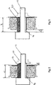
- Fig. 2
- is a cross section of a pulley in a first position;
- Fig. 3
- is a cross section of the pulley of
Fig. 2 in a second position; - Fig. 4
- is a schematic of a belt drive including the pulley of
Fig. 2 in the first position; - Fig. 5
- is a schematic of a belt drive including the pulley of
Fig. 2 in the second position. - The drawings are provided by way of reference only, and will be acknowledged as not to scale.
- With reference to
Fig. 1 , there is shown a self-aligningbelt pulley 10. The belt pulley is configured to automatically self-align should it be used in a drive system where there is an offset between the planes of the pulleys. The self-aligningpulley 10 comprises awheel 12, acollar 14, an anti-rotation means (key) 16, abolt 18 and a nut 20 (seefigures 2 and 3 ). - The
wheel 12 in this specific embodiment is a grooved pulley for use with a multi-v belt for instance, the serpentine or fan belt of an internal combustion engine. Thewheel 12 has grooves on its outer circumference for engagement with a multi-v belt. In other embodiments the pulley may have a smooth outer surface, for example for use as a back side belt pulley in a belt drive system or any other style of pulley. Thewheel 12 further comprises akeyway 22 for receiving thekey 16. - The
collar 14 comprises akeyway 24 for receiving thekey 16. Thecollar 14 supports thewheel 12 relative to thebolt 18 and permits rotational movement of thewheel 12 relative to thebolt 18. Thecollar 14 may be a plain bearing or in alternative embodiment any mean that permits rotation about thebolt 18 for example a needle roller bearing. - The key 16 in this embodiment is a
key 16 is received in thekeyway 22 of thewheel 12 and thekeyway 24 of thecollar 14. The key 16 prevents relative rotational movement of thecollar 14 and thewheel 12. Translational movement of thewheel 12 relative to thecollar 14 along the axis L is unrestricted. That is, thewheel 12 can slide relative to thekey 16 andcollar 14. In other embodiments, other means for preventing rotational movement of thewheel 12 relative to thecollar 14 whilst permitting sliding motion may be used for example a series of interlocking splines. - The width W of the
wheel 12 is smaller than the length Z of thecollar 14. This difference in dimensions between the width W and length Z permits thewheel 12 to slide relative to thecollar 14 by a distance of X. It will be understood that in other embodiments, these dimensions will be modified to suit the particular application of the invention. - The
bolt 18 is a high tensile steel bolt, however may be any suitable fastener for the particular application. Thebolt 18 is received through the centre of thecollar 14. Thecollar 14 being freely rotatable about the shank of thebolt 18. - The nut 20 (see
figures 2 and 3 ) is a flange head nut. In other embodiments any suitable retainer may be used, indeed, the nut may be replaced by a press fit steel washer or a retaining pin through the hank of thebolt 18. In some embodiments thenut 20 may not be required. For example when thebolt 20 is attaching thewheel 12 to a protruding boss on an engine block. Thenut 20 in the embodiments shown infigures 2 and 3 retain thecollar 14,key 16 andwheel 12 on thebolt 18. - Referring now to
figures 4 and 5 , there is shown a schematic belt drive system. The belt drive system comprises a self-aligningbelt pulley 10, a standard knownbelt pulley 26 and abelt 28. Thepulleys surface 30 for example the front face of an engine block. As is shown infigure 4 , the planes of rotation of thepulleys belt 28. - The misalignment of the pulleys may be caused by dimensional tolerance differences in machining of the
surface 30 and or of the pulleys themselves. Thewheel 12 of self-aligningpulley 10 moves by a distance of X in the direction D to the position shown infigure 5 thereby aligning the planes of thepulleys belt 28. - The invention is not limited to the embodiments or examples described herein, and may be modified or adapted without departing from the scope of the present invention.
Claims (6)
- A self-aligning belt pulley for a belt drive system e.g. a FEAD system, the self-aligning pulley comprising:a wheel;a bolt;a collar; anda anti-rotation means, wherein the bolt is received through the centre of the collar and the collar is freely rotatable on the bolt, and the wheel is supported by the collar and rotationally fixed to the collar by the anti-rotation means and wherein the wheel is slideable relative to the collar.
- A self-aligning belt pulley according to claim 1 wherein the anti-rotation means comprises a key and keyway.
- A self-aligning belt pulley according to claim 1 wherein the anti-rotation means comprises a number of interlocking splines.
- A self-aligning belt pulley according to claim 1 wherein the collar comprises a bearing
- A self-aligning belt pulley according to claim 4 wherein the collar comprises a plain bearing.
- A self-aligning belt pulley according to claim 4 wherein the collar comprises a spindle roller bearing.
Applications Claiming Priority (1)
| Application Number | Priority Date | Filing Date | Title |
|---|---|---|---|
| GBGB1816768.4A GB201816768D0 (en) | 2018-10-15 | 2018-10-15 | Self-aligning belt pulley |
Publications (2)
| Publication Number | Publication Date |
|---|---|
| EP3640448A1 true EP3640448A1 (en) | 2020-04-22 |
| EP3640448B1 EP3640448B1 (en) | 2021-07-07 |
Family
ID=64394987
Family Applications (1)
| Application Number | Title | Priority Date | Filing Date |
|---|---|---|---|
| EP19201642.6A Active EP3640448B1 (en) | 2018-10-15 | 2019-10-07 | Self-aligning belt pulley |
Country Status (2)
| Country | Link |
|---|---|
| EP (1) | EP3640448B1 (en) |
| GB (1) | GB201816768D0 (en) |
Citations (3)
| Publication number | Priority date | Publication date | Assignee | Title |
|---|---|---|---|---|
| US20040077445A1 (en) * | 2002-10-17 | 2004-04-22 | Prior Gregory Paul | Engine accessory belt drive with self-aligning pulley |
| CN105936136A (en) * | 2015-03-03 | 2016-09-14 | 乔治·佩特拉托 | Wheel pressing devices for folding-gluing machines and related folding-gluing machines |
| US20170082177A1 (en) * | 2015-09-17 | 2017-03-23 | Dayco Ip Holdings, Llc | Self-aligning pulley |
-
2018
- 2018-10-15 GB GBGB1816768.4A patent/GB201816768D0/en not_active Ceased
-
2019
- 2019-10-07 EP EP19201642.6A patent/EP3640448B1/en active Active
Patent Citations (3)
| Publication number | Priority date | Publication date | Assignee | Title |
|---|---|---|---|---|
| US20040077445A1 (en) * | 2002-10-17 | 2004-04-22 | Prior Gregory Paul | Engine accessory belt drive with self-aligning pulley |
| CN105936136A (en) * | 2015-03-03 | 2016-09-14 | 乔治·佩特拉托 | Wheel pressing devices for folding-gluing machines and related folding-gluing machines |
| US20170082177A1 (en) * | 2015-09-17 | 2017-03-23 | Dayco Ip Holdings, Llc | Self-aligning pulley |
Also Published As
| Publication number | Publication date |
|---|---|
| GB201816768D0 (en) | 2018-11-28 |
| EP3640448B1 (en) | 2021-07-07 |
Similar Documents
| Publication | Publication Date | Title |
|---|---|---|
| US7344313B2 (en) | Taper lock bearing assembly | |
| US20250215939A1 (en) | Reverse-input blocking clutch | |
| US20220060084A1 (en) | Electric motor with reverse input cutoff clutch | |
| KR20090074068A (en) | Transfer pumps with improved bearings on the drive shaft, in particular transfer pumps for the transfer of diesel fuel | |
| WO2015012053A1 (en) | Pulley device with embedded unidirectional clutch | |
| US8393800B2 (en) | Needle roller bearing and crankshaft support structure | |
| US20170159735A1 (en) | Adjusting Device for a Disc Brake, and Disc Brake with Such an Adjusting Device | |
| KR960011632B1 (en) | Roller bearing clutch | |
| US12117051B2 (en) | Reverse-input blocking clutch | |
| CA2633682C (en) | Bearing anti creep device & method | |
| EP3640448A1 (en) | Self-aligning belt pulley | |
| US20170082177A1 (en) | Self-aligning pulley | |
| US6682226B2 (en) | Cylindrical roller bearing with preload capability | |
| US10359102B2 (en) | Friction roller-type reduction gear | |
| US3014380A (en) | Motion-transmitting device | |
| US20210048063A1 (en) | Bearing support structure | |
| KR101252328B1 (en) | Linear motion machine with servo motor | |
| CN111379619A (en) | Variable compression ratio mechanism and control method thereof | |
| US8402856B2 (en) | Engine tapered gear assembly | |
| CN115143195B (en) | A sliding heavy-duty coupling | |
| JP7768265B2 (en) | Ball screw device | |
| US20160053831A1 (en) | One-way clutch device | |
| US7641558B2 (en) | Constant velocity joint | |
| US11280384B2 (en) | Balance shaft assembly | |
| JP2007218394A (en) | Two-split bearing |
Legal Events
| Date | Code | Title | Description |
|---|---|---|---|
| PUAI | Public reference made under article 153(3) epc to a published international application that has entered the european phase |
Free format text: ORIGINAL CODE: 0009012 |
|
| STAA | Information on the status of an ep patent application or granted ep patent |
Free format text: STATUS: THE APPLICATION HAS BEEN PUBLISHED |
|
| AK | Designated contracting states |
Kind code of ref document: A1 Designated state(s): AL AT BE BG CH CY CZ DE DK EE ES FI FR GB GR HR HU IE IS IT LI LT LU LV MC MK MT NL NO PL PT RO RS SE SI SK SM TR |
|
| AX | Request for extension of the european patent |
Extension state: BA ME |
|
| STAA | Information on the status of an ep patent application or granted ep patent |
Free format text: STATUS: REQUEST FOR EXAMINATION WAS MADE |
|
| 17P | Request for examination filed |
Effective date: 20201022 |
|
| RBV | Designated contracting states (corrected) |
Designated state(s): AL AT BE BG CH CY CZ DE DK EE ES FI FR GB GR HR HU IE IS IT LI LT LU LV MC MK MT NL NO PL PT RO RS SE SI SK SM TR |
|
| GRAP | Despatch of communication of intention to grant a patent |
Free format text: ORIGINAL CODE: EPIDOSNIGR1 |
|
| STAA | Information on the status of an ep patent application or granted ep patent |
Free format text: STATUS: GRANT OF PATENT IS INTENDED |
|
| INTG | Intention to grant announced |
Effective date: 20210316 |
|
| GRAS | Grant fee paid |
Free format text: ORIGINAL CODE: EPIDOSNIGR3 |
|
| GRAA | (expected) grant |
Free format text: ORIGINAL CODE: 0009210 |
|
| STAA | Information on the status of an ep patent application or granted ep patent |
Free format text: STATUS: THE PATENT HAS BEEN GRANTED |
|
| AK | Designated contracting states |
Kind code of ref document: B1 Designated state(s): AL AT BE BG CH CY CZ DE DK EE ES FI FR GB GR HR HU IE IS IT LI LT LU LV MC MK MT NL NO PL PT RO RS SE SI SK SM TR |
|
| REG | Reference to a national code |
Ref country code: GB Ref legal event code: FG4D |
|
| REG | Reference to a national code |
Ref country code: AT Ref legal event code: REF Ref document number: 1408801 Country of ref document: AT Kind code of ref document: T Effective date: 20210715 |
|
| REG | Reference to a national code |
Ref country code: DE Ref legal event code: R096 Ref document number: 602019005907 Country of ref document: DE |
|
| REG | Reference to a national code |
Ref country code: IE Ref legal event code: FG4D |
|
| REG | Reference to a national code |
Ref country code: LT Ref legal event code: MG9D |
|
| REG | Reference to a national code |
Ref country code: NL Ref legal event code: MP Effective date: 20210707 |
|
| REG | Reference to a national code |
Ref country code: AT Ref legal event code: MK05 Ref document number: 1408801 Country of ref document: AT Kind code of ref document: T Effective date: 20210707 |
|
| PG25 | Lapsed in a contracting state [announced via postgrant information from national office to epo] |
Ref country code: ES Free format text: LAPSE BECAUSE OF FAILURE TO SUBMIT A TRANSLATION OF THE DESCRIPTION OR TO PAY THE FEE WITHIN THE PRESCRIBED TIME-LIMIT Effective date: 20210707 Ref country code: RS Free format text: LAPSE BECAUSE OF FAILURE TO SUBMIT A TRANSLATION OF THE DESCRIPTION OR TO PAY THE FEE WITHIN THE PRESCRIBED TIME-LIMIT Effective date: 20210707 Ref country code: SE Free format text: LAPSE BECAUSE OF FAILURE TO SUBMIT A TRANSLATION OF THE DESCRIPTION OR TO PAY THE FEE WITHIN THE PRESCRIBED TIME-LIMIT Effective date: 20210707 Ref country code: LT Free format text: LAPSE BECAUSE OF FAILURE TO SUBMIT A TRANSLATION OF THE DESCRIPTION OR TO PAY THE FEE WITHIN THE PRESCRIBED TIME-LIMIT Effective date: 20210707 Ref country code: AT Free format text: LAPSE BECAUSE OF FAILURE TO SUBMIT A TRANSLATION OF THE DESCRIPTION OR TO PAY THE FEE WITHIN THE PRESCRIBED TIME-LIMIT Effective date: 20210707 Ref country code: BG Free format text: LAPSE BECAUSE OF FAILURE TO SUBMIT A TRANSLATION OF THE DESCRIPTION OR TO PAY THE FEE WITHIN THE PRESCRIBED TIME-LIMIT Effective date: 20211007 Ref country code: FI Free format text: LAPSE BECAUSE OF FAILURE TO SUBMIT A TRANSLATION OF THE DESCRIPTION OR TO PAY THE FEE WITHIN THE PRESCRIBED TIME-LIMIT Effective date: 20210707 Ref country code: HR Free format text: LAPSE BECAUSE OF FAILURE TO SUBMIT A TRANSLATION OF THE DESCRIPTION OR TO PAY THE FEE WITHIN THE PRESCRIBED TIME-LIMIT Effective date: 20210707 Ref country code: NO Free format text: LAPSE BECAUSE OF FAILURE TO SUBMIT A TRANSLATION OF THE DESCRIPTION OR TO PAY THE FEE WITHIN THE PRESCRIBED TIME-LIMIT Effective date: 20211007 Ref country code: PT Free format text: LAPSE BECAUSE OF FAILURE TO SUBMIT A TRANSLATION OF THE DESCRIPTION OR TO PAY THE FEE WITHIN THE PRESCRIBED TIME-LIMIT Effective date: 20211108 Ref country code: NL Free format text: LAPSE BECAUSE OF FAILURE TO SUBMIT A TRANSLATION OF THE DESCRIPTION OR TO PAY THE FEE WITHIN THE PRESCRIBED TIME-LIMIT Effective date: 20210707 |
|
| PG25 | Lapsed in a contracting state [announced via postgrant information from national office to epo] |
Ref country code: PL Free format text: LAPSE BECAUSE OF FAILURE TO SUBMIT A TRANSLATION OF THE DESCRIPTION OR TO PAY THE FEE WITHIN THE PRESCRIBED TIME-LIMIT Effective date: 20210707 Ref country code: LV Free format text: LAPSE BECAUSE OF FAILURE TO SUBMIT A TRANSLATION OF THE DESCRIPTION OR TO PAY THE FEE WITHIN THE PRESCRIBED TIME-LIMIT Effective date: 20210707 Ref country code: GR Free format text: LAPSE BECAUSE OF FAILURE TO SUBMIT A TRANSLATION OF THE DESCRIPTION OR TO PAY THE FEE WITHIN THE PRESCRIBED TIME-LIMIT Effective date: 20211008 |
|
| REG | Reference to a national code |
Ref country code: DE Ref legal event code: R097 Ref document number: 602019005907 Country of ref document: DE |
|
| PG25 | Lapsed in a contracting state [announced via postgrant information from national office to epo] |
Ref country code: DK Free format text: LAPSE BECAUSE OF FAILURE TO SUBMIT A TRANSLATION OF THE DESCRIPTION OR TO PAY THE FEE WITHIN THE PRESCRIBED TIME-LIMIT Effective date: 20210707 |
|
| PLBE | No opposition filed within time limit |
Free format text: ORIGINAL CODE: 0009261 |
|
| STAA | Information on the status of an ep patent application or granted ep patent |
Free format text: STATUS: NO OPPOSITION FILED WITHIN TIME LIMIT |
|
| PG25 | Lapsed in a contracting state [announced via postgrant information from national office to epo] |
Ref country code: SM Free format text: LAPSE BECAUSE OF FAILURE TO SUBMIT A TRANSLATION OF THE DESCRIPTION OR TO PAY THE FEE WITHIN THE PRESCRIBED TIME-LIMIT Effective date: 20210707 Ref country code: SK Free format text: LAPSE BECAUSE OF FAILURE TO SUBMIT A TRANSLATION OF THE DESCRIPTION OR TO PAY THE FEE WITHIN THE PRESCRIBED TIME-LIMIT Effective date: 20210707 Ref country code: RO Free format text: LAPSE BECAUSE OF FAILURE TO SUBMIT A TRANSLATION OF THE DESCRIPTION OR TO PAY THE FEE WITHIN THE PRESCRIBED TIME-LIMIT Effective date: 20210707 Ref country code: EE Free format text: LAPSE BECAUSE OF FAILURE TO SUBMIT A TRANSLATION OF THE DESCRIPTION OR TO PAY THE FEE WITHIN THE PRESCRIBED TIME-LIMIT Effective date: 20210707 Ref country code: CZ Free format text: LAPSE BECAUSE OF FAILURE TO SUBMIT A TRANSLATION OF THE DESCRIPTION OR TO PAY THE FEE WITHIN THE PRESCRIBED TIME-LIMIT Effective date: 20210707 Ref country code: AL Free format text: LAPSE BECAUSE OF FAILURE TO SUBMIT A TRANSLATION OF THE DESCRIPTION OR TO PAY THE FEE WITHIN THE PRESCRIBED TIME-LIMIT Effective date: 20210707 |
|
| REG | Reference to a national code |
Ref country code: DE Ref legal event code: R084 Ref document number: 602019005907 Country of ref document: DE |
|
| 26N | No opposition filed |
Effective date: 20220408 |
|
| REG | Reference to a national code |
Ref country code: BE Ref legal event code: MM Effective date: 20211031 |
|
| PG25 | Lapsed in a contracting state [announced via postgrant information from national office to epo] |
Ref country code: MC Free format text: LAPSE BECAUSE OF FAILURE TO SUBMIT A TRANSLATION OF THE DESCRIPTION OR TO PAY THE FEE WITHIN THE PRESCRIBED TIME-LIMIT Effective date: 20210707 |
|
| PG25 | Lapsed in a contracting state [announced via postgrant information from national office to epo] |
Ref country code: LU Free format text: LAPSE BECAUSE OF NON-PAYMENT OF DUE FEES Effective date: 20211007 Ref country code: IT Free format text: LAPSE BECAUSE OF FAILURE TO SUBMIT A TRANSLATION OF THE DESCRIPTION OR TO PAY THE FEE WITHIN THE PRESCRIBED TIME-LIMIT Effective date: 20210707 Ref country code: BE Free format text: LAPSE BECAUSE OF NON-PAYMENT OF DUE FEES Effective date: 20211031 |
|
| PG25 | Lapsed in a contracting state [announced via postgrant information from national office to epo] |
Ref country code: IE Free format text: LAPSE BECAUSE OF NON-PAYMENT OF DUE FEES Effective date: 20211007 |
|
| REG | Reference to a national code |
Ref country code: CH Ref legal event code: PL |
|
| P01 | Opt-out of the competence of the unified patent court (upc) registered |
Effective date: 20230518 |
|
| PG25 | Lapsed in a contracting state [announced via postgrant information from national office to epo] |
Ref country code: CY Free format text: LAPSE BECAUSE OF FAILURE TO SUBMIT A TRANSLATION OF THE DESCRIPTION OR TO PAY THE FEE WITHIN THE PRESCRIBED TIME-LIMIT Effective date: 20210707 |
|
| PG25 | Lapsed in a contracting state [announced via postgrant information from national office to epo] |
Ref country code: LI Free format text: LAPSE BECAUSE OF NON-PAYMENT OF DUE FEES Effective date: 20221031 Ref country code: HU Free format text: LAPSE BECAUSE OF FAILURE TO SUBMIT A TRANSLATION OF THE DESCRIPTION OR TO PAY THE FEE WITHIN THE PRESCRIBED TIME-LIMIT; INVALID AB INITIO Effective date: 20191007 Ref country code: CH Free format text: LAPSE BECAUSE OF NON-PAYMENT OF DUE FEES Effective date: 20221031 |
|
| PG25 | Lapsed in a contracting state [announced via postgrant information from national office to epo] |
Ref country code: MK Free format text: LAPSE BECAUSE OF FAILURE TO SUBMIT A TRANSLATION OF THE DESCRIPTION OR TO PAY THE FEE WITHIN THE PRESCRIBED TIME-LIMIT Effective date: 20210707 |
|
| GBPC | Gb: european patent ceased through non-payment of renewal fee |
Effective date: 20231007 |
|
| PG25 | Lapsed in a contracting state [announced via postgrant information from national office to epo] |
Ref country code: TR Free format text: LAPSE BECAUSE OF FAILURE TO SUBMIT A TRANSLATION OF THE DESCRIPTION OR TO PAY THE FEE WITHIN THE PRESCRIBED TIME-LIMIT Effective date: 20210707 |
|
| PG25 | Lapsed in a contracting state [announced via postgrant information from national office to epo] |
Ref country code: GB Free format text: LAPSE BECAUSE OF NON-PAYMENT OF DUE FEES Effective date: 20231007 |
|
| PG25 | Lapsed in a contracting state [announced via postgrant information from national office to epo] |
Ref country code: GB Free format text: LAPSE BECAUSE OF NON-PAYMENT OF DUE FEES Effective date: 20231007 |
|
| PG25 | Lapsed in a contracting state [announced via postgrant information from national office to epo] |
Ref country code: MT Free format text: LAPSE BECAUSE OF FAILURE TO SUBMIT A TRANSLATION OF THE DESCRIPTION OR TO PAY THE FEE WITHIN THE PRESCRIBED TIME-LIMIT Effective date: 20210707 |
|
| PGFP | Annual fee paid to national office [announced via postgrant information from national office to epo] |
Ref country code: DE Payment date: 20251021 Year of fee payment: 7 |
|
| PGFP | Annual fee paid to national office [announced via postgrant information from national office to epo] |
Ref country code: FR Payment date: 20251030 Year of fee payment: 7 |