EP3640440A1 - Stator attachment system for gas turbine engine - Google Patents
Stator attachment system for gas turbine engine Download PDFInfo
- Publication number
- EP3640440A1 EP3640440A1 EP19203121.9A EP19203121A EP3640440A1 EP 3640440 A1 EP3640440 A1 EP 3640440A1 EP 19203121 A EP19203121 A EP 19203121A EP 3640440 A1 EP3640440 A1 EP 3640440A1
- Authority
- EP
- European Patent Office
- Prior art keywords
- stator
- tab
- compressor case
- tab portion
- retention
- Prior art date
- Legal status (The legal status is an assumption and is not a legal conclusion. Google has not performed a legal analysis and makes no representation as to the accuracy of the status listed.)
- Granted
Links
Images




Classifications
-
- F—MECHANICAL ENGINEERING; LIGHTING; HEATING; WEAPONS; BLASTING
- F01—MACHINES OR ENGINES IN GENERAL; ENGINE PLANTS IN GENERAL; STEAM ENGINES
- F01D—NON-POSITIVE DISPLACEMENT MACHINES OR ENGINES, e.g. STEAM TURBINES
- F01D25/00—Component parts, details, or accessories, not provided for in, or of interest apart from, other groups
- F01D25/24—Casings; Casing parts, e.g. diaphragms, casing fastenings
-
- F—MECHANICAL ENGINEERING; LIGHTING; HEATING; WEAPONS; BLASTING
- F01—MACHINES OR ENGINES IN GENERAL; ENGINE PLANTS IN GENERAL; STEAM ENGINES
- F01D—NON-POSITIVE DISPLACEMENT MACHINES OR ENGINES, e.g. STEAM TURBINES
- F01D9/00—Stators
- F01D9/02—Nozzles; Nozzle boxes; Stator blades; Guide conduits, e.g. individual nozzles
- F01D9/04—Nozzles; Nozzle boxes; Stator blades; Guide conduits, e.g. individual nozzles forming ring or sector
- F01D9/042—Nozzles; Nozzle boxes; Stator blades; Guide conduits, e.g. individual nozzles forming ring or sector fixing blades to stators
-
- F—MECHANICAL ENGINEERING; LIGHTING; HEATING; WEAPONS; BLASTING
- F01—MACHINES OR ENGINES IN GENERAL; ENGINE PLANTS IN GENERAL; STEAM ENGINES
- F01D—NON-POSITIVE DISPLACEMENT MACHINES OR ENGINES, e.g. STEAM TURBINES
- F01D25/00—Component parts, details, or accessories, not provided for in, or of interest apart from, other groups
- F01D25/24—Casings; Casing parts, e.g. diaphragms, casing fastenings
- F01D25/243—Flange connections; Bolting arrangements
-
- F—MECHANICAL ENGINEERING; LIGHTING; HEATING; WEAPONS; BLASTING
- F01—MACHINES OR ENGINES IN GENERAL; ENGINE PLANTS IN GENERAL; STEAM ENGINES
- F01D—NON-POSITIVE DISPLACEMENT MACHINES OR ENGINES, e.g. STEAM TURBINES
- F01D25/00—Component parts, details, or accessories, not provided for in, or of interest apart from, other groups
- F01D25/24—Casings; Casing parts, e.g. diaphragms, casing fastenings
- F01D25/246—Fastening of diaphragms or stator-rings
-
- F—MECHANICAL ENGINEERING; LIGHTING; HEATING; WEAPONS; BLASTING
- F01—MACHINES OR ENGINES IN GENERAL; ENGINE PLANTS IN GENERAL; STEAM ENGINES
- F01D—NON-POSITIVE DISPLACEMENT MACHINES OR ENGINES, e.g. STEAM TURBINES
- F01D25/00—Component parts, details, or accessories, not provided for in, or of interest apart from, other groups
- F01D25/24—Casings; Casing parts, e.g. diaphragms, casing fastenings
- F01D25/26—Double casings; Measures against temperature strain in casings
-
- F—MECHANICAL ENGINEERING; LIGHTING; HEATING; WEAPONS; BLASTING
- F01—MACHINES OR ENGINES IN GENERAL; ENGINE PLANTS IN GENERAL; STEAM ENGINES
- F01D—NON-POSITIVE DISPLACEMENT MACHINES OR ENGINES, e.g. STEAM TURBINES
- F01D25/00—Component parts, details, or accessories, not provided for in, or of interest apart from, other groups
- F01D25/24—Casings; Casing parts, e.g. diaphragms, casing fastenings
- F01D25/26—Double casings; Measures against temperature strain in casings
- F01D25/265—Vertically split casings; Clamping arrangements therefor
-
- F—MECHANICAL ENGINEERING; LIGHTING; HEATING; WEAPONS; BLASTING
- F04—POSITIVE - DISPLACEMENT MACHINES FOR LIQUIDS; PUMPS FOR LIQUIDS OR ELASTIC FLUIDS
- F04D—NON-POSITIVE-DISPLACEMENT PUMPS
- F04D29/00—Details, component parts, or accessories
- F04D29/40—Casings; Connections of working fluid
- F04D29/52—Casings; Connections of working fluid for axial pumps
- F04D29/54—Fluid-guiding means, e.g. diffusers
- F04D29/541—Specially adapted for elastic fluid pumps
- F04D29/542—Bladed diffusers
-
- F—MECHANICAL ENGINEERING; LIGHTING; HEATING; WEAPONS; BLASTING
- F04—POSITIVE - DISPLACEMENT MACHINES FOR LIQUIDS; PUMPS FOR LIQUIDS OR ELASTIC FLUIDS
- F04D—NON-POSITIVE-DISPLACEMENT PUMPS
- F04D29/00—Details, component parts, or accessories
- F04D29/60—Mounting; Assembling; Disassembling
- F04D29/64—Mounting; Assembling; Disassembling of axial pumps
- F04D29/644—Mounting; Assembling; Disassembling of axial pumps especially adapted for elastic fluid pumps
-
- F—MECHANICAL ENGINEERING; LIGHTING; HEATING; WEAPONS; BLASTING
- F05—INDEXING SCHEMES RELATING TO ENGINES OR PUMPS IN VARIOUS SUBCLASSES OF CLASSES F01-F04
- F05D—INDEXING SCHEME FOR ASPECTS RELATING TO NON-POSITIVE-DISPLACEMENT MACHINES OR ENGINES, GAS-TURBINES OR JET-PROPULSION PLANTS
- F05D2240/00—Components
- F05D2240/10—Stators
- F05D2240/12—Fluid guiding means, e.g. vanes
-
- F—MECHANICAL ENGINEERING; LIGHTING; HEATING; WEAPONS; BLASTING
- F05—INDEXING SCHEMES RELATING TO ENGINES OR PUMPS IN VARIOUS SUBCLASSES OF CLASSES F01-F04
- F05D—INDEXING SCHEME FOR ASPECTS RELATING TO NON-POSITIVE-DISPLACEMENT MACHINES OR ENGINES, GAS-TURBINES OR JET-PROPULSION PLANTS
- F05D2260/00—Function
- F05D2260/30—Retaining components in desired mutual position
- F05D2260/36—Retaining components in desired mutual position by a form fit connection, e.g. by interlocking
Definitions
- Gas turbine engines may be employed to power various devices.
- a gas turbine engine may be employed to power a mobile platform, such as an aircraft.
- gas turbine engines have a case that surrounds components of the gas turbine engine to protect the engine components and the surroundings.
- one or more portions of the case may be split into two or more pieces to facilitate the maintenance of the associated components of the gas turbine engine.
- a case surrounding a compressor section of the gas turbine engine may be split, to enable maintenance of the components associated with the compressor section.
- the split of the case surrounding the compressor section generally requires that the components associated with the compressor section are able to be coupled to a respective half of the case while maintaining co-axial alignment during operation of the gas turbine engine.
- stator attachment is described herein as being used with a stator of a compressor section of a gas turbine engine onboard a mobile platform, such as a bus, motorcycle, train, motor vehicle, marine vessel, aircraft, rotorcraft and the like, the various teachings of the present disclosure can be used with a gas turbine engine on a stationary platform.
- a mobile platform such as a bus, motorcycle, train, motor vehicle, marine vessel, aircraft, rotorcraft and the like
- many alternative or additional functional relationships or physical connections may be present in an embodiment of the present disclosure.
- figures shown herein depict an example with certain arrangements of elements, additional intervening elements, devices, features, or components may be present in an actual embodiment. It should also be understood that the drawings are merely illustrative and may not be drawn to scale.
- the high pressure air is mixed with fuel, which is combusted.
- the high-temperature combustion air or combustive gas flow is directed into the turbine section 118.
- the turbine section 118 includes one or more turbines 134 disposed in axial flow series. It will be appreciated that the number of turbines, and/or the configurations thereof, may vary.
- the combustive gas expands through and rotates the turbines 134.
- the combustive gas flow then exits turbine section 118 for mixture with the cooler bypass airflow from the outer bypass duct 106 and is ultimately discharged from gas turbine engine 100 through exhaust section 120.
- the compressor section 114 includes four compressors 130a-130d, which sequentially raise the pressure of the air.
- Each of the compressors 130a-130d includes a plurality of airfoils 180, which are coupled to a respective rotor 182.
- the compressors 130a-130d are each contained within the compressor case 204, which is axially split along the longitudinal axis 140 ( FIG. 1 ).
- the compressor section 114 also includes at least one variable vane stator 206 and at least one fixed vane stator 202.
- the stator attachment system 200 couples each of the fixed vane stators 202a-202c to the compressor case 204, and in this example, each of the fixed vane stators 202a-202c is substantially the same.
- the stator attachment system 200 will be discussed herein with regard to the fixed vane stator 202a with the understanding that the stator attachment system 200 for each of the fixed vane stators 202b, 202c is the same.
- FIG. 3 is a front end view of the compressor case 204 taken from the perspective of line 3-3 of FIG. 2 , in which a first half 204a of the compressor case 204 is coupled to a second half 204b of the compressor case 204.
- the compressor case 204 is substantially annular and is symmetric about the longitudinal axis 140 such that the first half 204a and the second half 204b are symmetric about the longitudinal axis 140.
- the grooves 222 are each defined within an interior surface 224 of the respective half 204a, 204b to extend along the interior surface 224 between the mounting flanges 219 in a semi-circular shape.
- Each of the grooves 222 includes at least one or a pair of channels 223.
- the pair of channels 223 provides a guide to receive a portion of the fixed vane stator 202 within the groove 222 and provide clearance for a portion of the fixed vane stator 202a.
- the plurality of retention slots 225 includes a first retention slot portion 226, a second retention slot 228 and a third retention slot portion 230.
- the first retention slot portion 226, the second retention slot 228 and the third retention slot portion 230 are spaced apart about the perimeter of the groove 222.
- the inner seal interface 258 includes a first leg 312, a second leg 314 and a third leg 316.
- the first leg 312 is coupled to or integrally formed with the inner platform 256, and the second leg 314.
- the second leg 314 is coupled to or integrally formed with the first leg 312 and the third leg 316.
- the second leg 314 extends along an axis, which is substantially oblique to the longitudinal axis 140. It should be noted that the second leg 314 may extend along the axis to define a positive or negative angle with the longitudinal axis 140 depending upon the position of the fixed vane stator 202 in the compressor section 114.
- the sealing member 260 is inserted into the slot 296 of the outer platform 254 of the first stator half 250.
- the pins 285 are positioned within the coupling bores 283 to couple the first stator half 250 to the second stator half 252. It should be noted that in other embodiments, the pins 285 may be integrally formed with the first stator half 250 or the second stator half 252 to reduce assembly time, if desired. This process may be repeated for each of the fixed vane stators 202b, 202c.
Landscapes
- Engineering & Computer Science (AREA)
- Mechanical Engineering (AREA)
- General Engineering & Computer Science (AREA)
- Structures Of Non-Positive Displacement Pumps (AREA)
Abstract
Description
- The present disclosure generally relates to gas turbine engines, and more particularly relates to a stator attachment system for a gas turbine engine having a split compressor case.
- Gas turbine engines may be employed to power various devices. For example, a gas turbine engine may be employed to power a mobile platform, such as an aircraft. Generally, gas turbine engines have a case that surrounds components of the gas turbine engine to protect the engine components and the surroundings. In certain instances, one or more portions of the case may be split into two or more pieces to facilitate the maintenance of the associated components of the gas turbine engine. For example, a case surrounding a compressor section of the gas turbine engine may be split, to enable maintenance of the components associated with the compressor section. The split of the case surrounding the compressor section generally requires that the components associated with the compressor section are able to be coupled to a respective half of the case while maintaining co-axial alignment during operation of the gas turbine engine. In certain instances, in order to couple components associated with the compressor section to the respective half of the case, the compressor component, such as a stator, is split into individual stator pieces, which are individually machined to be received within respective individual pilot bores machined into the case. This increases part count, manufacturing time and assembly time for the gas turbine engine.
- Accordingly, it is desirable to provide a stator attachment for a gas turbine engine, which maintains co-axial alignment while reducing part count, manufacturing time and assembly time. Furthermore, other desirable features and characteristics of the present invention will become apparent from the subsequent detailed description and the appended claims, taken in conjunction with the accompanying drawings and the foregoing technical field and background.
- In accordance with various embodiments, provided is a stator attachment system for coupling a stator to a compressor case. The compressor case is split to define a first half and a second half. The stator attachment system includes a plurality of retention slots defined in each of the first half and the second half of the compressor case. The plurality of retention slots is spaced apart about a perimeter of the first half and the second half of the compressor case such that at least one of the plurality of retention slots associated with the first half is vertically aligned with at least one of the plurality of retention slots associated with the second half. The stator attachment system includes a plurality of tabs defined on the stator that extend radially outward from the stator. Each of the plurality of tabs is configured to engage with one of the plurality of retention slots to couple the stator to the compressor case.
- Also provided is a gas turbine engine. The gas turbine engine includes a split compressor case having a first half and a second half. Each of the first half and the second half has a plurality of retention slots spaced apart about a perimeter of the respective one of the first half and the second half. The gas turbine engine includes a stator having a plurality of fixed stator vanes. The stator is split to define a first stator half and a second stator half. Each of the first stator half and the second stator half has a plurality of tabs that extend radially outward from the respective one of the first stator half and the second stator half. Each tab of the plurality of tabs is configured to be received within a respective one of the plurality of retention slots to couple the first stator half to the first half of the compressor case and to couple the second stator half to the second half of the compressor case.
- Further provided is a gas turbine engine. The gas turbine engine includes a split compressor case having a first half and a second half. Each of the first half and the second half has a plurality of retention slots spaced apart about a perimeter of the respective one of the first half and the second half. The plurality of retention slots includes at least a first retention slot portion at a first end, a second retention slot and a third retention slot portion at a second end. The first end is opposite the second end. The gas turbine engine also includes a stator having a plurality of fixed stator vanes. The stator is split to define a first stator half and a second stator half. Each of the first stator half and the second stator half has a plurality of tabs that extend radially outward from the respective one of the first stator half and the second stator half. Each tab of the plurality of tabs is configured to be received within a respective one of the plurality of retention slots to couple the first stator half to the first half of the compressor case and to couple the second stator half to the second half of the compressor case.
- The exemplary embodiments will hereinafter be described in conjunction with the following drawing figures, wherein like numerals denote like elements, and wherein:
-
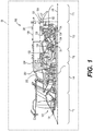
FIG. 1 is a schematic cross-sectional illustration of a gas turbine engine, which includes an exemplary stator attachment system for a gas turbine engine in accordance with the various teachings of the present disclosure; -
FIG. 2 is a detail cross-sectional view, taken atdetail 2 ofFIG. 1 , which illustrates a compressor section of the gas turbine engine which includes the stator attachment system ofFIG. 1 according to various embodiments; -
FIG. 3 is a front cross-sectional view of a compressor case surrounding a fixed vane stator, taken from the perspective of line 3-3 inFIG. 2 , in which the fixed vane stator is coupled to the compressor case with the stator attachment system and a plurality of sealing structures of the gas turbine engine inFIG. 2 are removed for clarity; -
FIG. 4 is a perspective view of the compressor case and the fixed vane stator in which the compressor case is expanded from the fixed vane stator and the plurality of sealing structures of the gas turbine engine inFIG. 2 are removed for clarity; -
FIG. 5 is a front cross-sectional view of the compressor case surrounding the fixed vane stator, taken from the perspective of line 5-5 inFIG. 2 , which illustrates the stator attachment system for coupling the fixed vane stator to the compressor case and the plurality of sealing structures of the gas turbine engine inFIG. 2 are removed for clarity; -
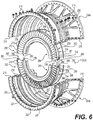
FIG. 6 is a perspective exploded view of the compressor case and the fixed vane stator and the plurality of sealing structures of the gas turbine engine inFIG. 2 are removed for clarity; -
FIG. 7A is a cross-sectional detail view of a portion of the stator attachment system, taken from the perspective of line 7A-7A inFIG. 5 , which illustrates a pin that couples a first half of the fixed vane stator to a second half of the fixed vane stator; -
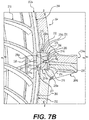
FIG. 7B is a cross-sectional detail view of a portion of the stator attachment system opposite the portion of the stator attachment system ofFIG. 7A , taken from the perspective of line 7B-7B inFIG. 5 , which illustrates a pin that couples a first half of the fixed vane stator to a second half of the fixed vane stator; -
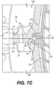
FIG. 7C is a detail cross-sectional view of a portion of the stator attachment system, taken atdetail 7C ofFIG. 5 , which illustrates respective first tab portions engaged with respective retention slot portions; and -
FIG. 8 is a detail cross-sectional view of a portion of the stator attachment system, taken atdetail 8 ofFIG. 5 , which illustrates a tab engaged with a retention slot. - The following detailed description is merely exemplary in nature and is not intended to limit the application and uses. Furthermore, there is no intention to be bound by any expressed or implied theory presented in the preceding technical field, background, brief summary or the following detailed description. In addition, those skilled in the art will appreciate that embodiments of the present disclosure may be practiced in conjunction with any type of component for use in a gas turbine engine having a split case, and the stator described herein for an axially split compressor case of a compressor section of a gas turbine engine is merely one exemplary embodiment according to the present disclosure. In addition, while the stator attachment is described herein as being used with a stator of a compressor section of a gas turbine engine onboard a mobile platform, such as a bus, motorcycle, train, motor vehicle, marine vessel, aircraft, rotorcraft and the like, the various teachings of the present disclosure can be used with a gas turbine engine on a stationary platform. Further, it should be noted that many alternative or additional functional relationships or physical connections may be present in an embodiment of the present disclosure. In addition, while the figures shown herein depict an example with certain arrangements of elements, additional intervening elements, devices, features, or components may be present in an actual embodiment. It should also be understood that the drawings are merely illustrative and may not be drawn to scale.
- As used herein, the term "axial" refers to a direction that is generally parallel to or coincident with an axis of rotation, axis of symmetry, or centerline of a component or components. For example, in a cylinder or disc with a centerline and generally circular ends or opposing faces, the "axial" direction may refer to the direction that generally extends in parallel to the centerline between the opposite ends or faces. In certain instances, the term "axial" may be utilized with respect to components that are not cylindrical (or otherwise radially symmetric). For example, the "axial" direction for a rectangular housing containing a rotating shaft may be viewed as a direction that is generally parallel to or coincident with the rotational axis of the shaft. Furthermore, the term "radially" as used herein may refer to a direction or a relationship of components with respect to a line extending outward from a shared centerline, axis, or similar reference, for example in a plane of a cylinder or disc that is perpendicular to the centerline or axis. In certain instances, components may be viewed as "radially" aligned even though one or both of the components may not be cylindrical (or otherwise radially symmetric). Furthermore, the terms "axial" and "radial" (and any derivatives) may encompass directional relationships that are other than precisely aligned with (e.g., oblique to) the true axial and radial dimensions, provided the relationship is predominately in the respective nominal axial or radial direction. As used herein, the term "transverse" denotes an axis that crosses another axis at an angle such that the axis and the other axis are neither substantially perpendicular nor substantially parallel. Also as used herein, the terms "integrally formed" and "integral" mean one-piece and exclude brazing, fasteners, or the like for maintaining portions thereon in a fixed relationship as a single unit.
- With reference to
FIG. 1 , a partial, cross-sectional view of an exemplarygas turbine engine 100 is shown with the remaining portion of thegas turbine engine 100 being substantially axisymmetric about alongitudinal axis 140, which also comprises an axis of rotation for thegas turbine engine 100. In the depicted embodiment, thegas turbine engine 100 is an annular multi-spool turbofan gas turbine jet engine within anaircraft 99, although other arrangements and uses may be provided. As will be discussed herein, thegas turbine engine 100 includes astator attachment system 200, which couples two halves of a fixedvane stator 202 to two halves of acompressor case 204 of acompressor section 114 of thegas turbine engine 100. Thestator attachment system 200 provides radial and axial piloting for the fixedvane stator 202 to maintain co-axial alignment of the fixedvane stator 202 during operation of thegas turbine engine 100. Further, thestator attachment system 200 reduces leakage in thecompressor section 114 by eliminating holes in the case for pilot bores (that would receive individual fixed vane stator pieces). As will be discussed, thestator attachment system 200 also eliminates the need for individual fixed vane stator pieces, as the fixedvane stator 202 may be configured as two half fixed vane stator arrays, which are received within a respective half of thecompressor case 204. This reduces part count, manufacturing and assembly time for thegas turbine engine 100. - In this example, with continued reference to
FIG. 1 , thegas turbine engine 100 includes afan section 112, thecompressor section 114, acombustor section 116, aturbine section 118, and anexhaust section 120. In one example, thefan section 112 includes afan 122 mounted on arotor 124 that draws air into thegas turbine engine 100 and accelerates it. A fraction of the accelerated air exhausted from thefan 122 is directed through theouter bypass duct 106 and the remaining fraction of air exhausted from thefan 122 is directed into thecompressor section 114. Theouter bypass duct 106 is generally defined by anouter casing 128 that is spaced apart from and surrounds theexhaust guide vane 126. - In the embodiment of
FIG. 1 , thecompressor section 114 includes one or more compressors 130. The number of compressors in thecompressor section 114 and the configuration thereof may vary. The one or more compressors 130 sequentially raise the pressure of the air and direct a majority of the high pressure air into thecombustor section 116. A fraction of the compressed air bypasses thecombustor section 116 and is used to cool, among other components, turbine blades in theturbine section 118. - In the embodiment of
FIG. 1 , in thecombustor section 116, which includes acombustion chamber 132, the high pressure air is mixed with fuel, which is combusted. The high-temperature combustion air or combustive gas flow is directed into theturbine section 118. In this example, theturbine section 118 includes one ormore turbines 134 disposed in axial flow series. It will be appreciated that the number of turbines, and/or the configurations thereof, may vary. The combustive gas expands through and rotates theturbines 134. The combustive gas flow then exitsturbine section 118 for mixture with the cooler bypass airflow from theouter bypass duct 106 and is ultimately discharged fromgas turbine engine 100 throughexhaust section 120. As theturbines 134 rotate, each drives equipment in thegas turbine engine 100 via concentrically disposed shafts or spools. Generally, theturbines 134 in theturbine section 118, the compressors 130 in thecompressor section 114 and thefan 122 are mechanically linked by one or more shafts or spools. For example, in a two spool turbofan engine platform, the turbine rotors contained within a high pressure (HP)turbine stage 136 may be rotationally fixed to the compressors 130 contained withincompressor section 114 by a HP shaft, while theturbines 134 contained within a low pressure (LP)turbine stage 138 may be rotationally fixed to therotor 124 of thefan 122 by a coaxial LP shaft. In other embodiments,gas turbine engine 100 may be a single spool engine or a multi-spool engine containing more than two coaxial shafts. - With reference to
FIG. 2 , a detail view of a portion of thecompressor section 114 is shown. In the example ofFIG. 2 , thecompressor section 114 includes fourcompressors 130a-130d, which sequentially raise the pressure of the air. Each of thecompressors 130a-130d includes a plurality ofairfoils 180, which are coupled to arespective rotor 182. Thecompressors 130a-130d are each contained within thecompressor case 204, which is axially split along the longitudinal axis 140 (FIG. 1 ). In this example, thecompressor section 114 also includes at least onevariable vane stator 206 and at least onefixed vane stator 202. Generally, thevariable vane stator 206 includes a plurality ofvariable stator vanes 208, which are each adjustable or movable relative to thecompressor case 204 to direct the airflow through thecompressor section 114. In contrast, the fixedvane stator 202 includes a plurality of fixedstator vanes 210 which are unmovable and remain in a fixed or stationary position relative to thecompressor case 204. In this example, thecompressor section 114 includes three fixedvane stators 202a-202c; however, thecompressor section 114 may include any number of fixedvane stators 202. Thecompressor section 114 also includes a plurality of sealingstructures 212, which reduce air leakage through thecompressor section 114. In this example, thestator attachment system 200 couples each of the fixedvane stators 202a-202c to thecompressor case 204, and in this example, each of the fixedvane stators 202a-202c is substantially the same. As thestator attachment system 200 is the same for each of the fixedvane stators 202a-202c, thestator attachment system 200 will be discussed herein with regard to the fixedvane stator 202a with the understanding that thestator attachment system 200 for each of the fixedvane stators - With reference to
FIG. 3 , the fixedvane stator 202a and thecompressor case 204 are shown in greater detail.FIG. 3 is a front end view of thecompressor case 204 taken from the perspective of line 3-3 ofFIG. 2 , in which afirst half 204a of thecompressor case 204 is coupled to asecond half 204b of thecompressor case 204. In this example, thecompressor case 204 is substantially annular and is symmetric about thelongitudinal axis 140 such that thefirst half 204a and thesecond half 204b are symmetric about thelongitudinal axis 140. As discussed, in this example, thecompressor case 204 is axially split into twohalves FIG. 4 ), including, but not limited to, bolts, screws, clips, pins, etc. In the example of bolts as themechanical fastener 218, a nut may be used to secure thehalves flange 219 that extends along a perimeter of therespective half halves compressor case 204 is composed of a suitable metal or metal alloy, including, but not limited to titanium, steel or nickel; and are formed by casting, machining, forging, direct metal laser sintering (DMLS), laser powder bed fusion (L-PBF), electron powder bed fusion (E-PBF), electron beam melting (EBM), etc. In one example, with reference toFIG. 4 , thecompressor case 204 is shown expanded from the fixedvane stator 202a. Eachhalf compressor case 204 includes a plurality ofgrooves 222 and a plurality ofretention slots 225. Thegrooves 222 each receive a respective one of the fixedvane stators 202. Thegrooves 222 are each defined within aninterior surface 224 of therespective half interior surface 224 between the mountingflanges 219 in a semi-circular shape. Each of thegrooves 222 includes at least one or a pair ofchannels 223. The pair ofchannels 223 provides a guide to receive a portion of the fixedvane stator 202 within thegroove 222 and provide clearance for a portion of the fixedvane stator 202a. In one example, the plurality ofretention slots 225 includes a firstretention slot portion 226, asecond retention slot 228 and a thirdretention slot portion 230. The firstretention slot portion 226, thesecond retention slot 228 and the thirdretention slot portion 230 are spaced apart about the perimeter of thegroove 222. Thechannels 223 are interconnected at discrete locations along therespective groove 222 by the firstretention slot portion 226, thesecond retention slot 228 and the thirdretention slot portion 230. Stated another way, the firstretention slot portion 226, thesecond retention slot 228 and the thirdretention slot portion 230 are orientated axially or extend along an axis substantially parallel to thelongitudinal axis 140 and parallel to a longitudinal axis of thecompressor case 204 such that the firstretention slot portion 226, thesecond retention slot 228 and the thirdretention slot portion 230 interconnect thechannels 223 of a respective one of thegrooves 222. - Each of the first
retention slot portion 226, thesecond retention slot 228 and the thirdretention slot portion 230 cooperate with the fixedvane stator 202 to define thestator attachment system 200. In this example, the firstretention slot portion 226 is defined on afirst end 232 of therespective half retention slot portion 230 is defined on an opposite,second end 234 of therespective half retention slot portion 226 and the thirdretention slot portion 230 are substantially the same, but are defined on opposite ends of therespective half retention slot portion 226, thesecond retention slot 228 and the thirdretention slot portion 230 are defined into theinterior surface 224 so as to extend into therespective half vane stator 202. Generally, the plurality ofretention slots 225 are defined in each of thefirst half 204a and thesecond half 204b of thecompressor case 204 so as to be spaced apart about a perimeter of thefirst half 204a and thesecond half 204b of thecompressor case 204. In one example, at least one of the plurality ofretention slots 225 associated with thefirst half 204a is vertically aligned with at least one of the plurality ofretention slots 225 of thesecond half 204b. In this example, thesecond retention slot 228 of each of thefirst half 204a and thesecond half 204b is vertically aligned along a vertical axis VA (FIG. 5 ). - With reference to
FIG. 5 , the firstretention slot portion 226 and the thirdretention slot portion 230 each extend for a distance D1, which is less than a distance D2 of thesecond retention slot 228. The firstretention slot portion 226 and the thirdretention slot portion 230 of thehalf 204a cooperate with the firstretention slot portion 226 and the thirdretention slot portion 230 of the half 204b when thecompressor case 204 is assembled to define a respective assembledretention slot retention slots - The
second retention slot 228 is defined between the firstretention slot portion 226 and the thirdretention slot portion 230. Generally, thesecond retention slot 228 of thehalf 204a is defined so as to be opposite thesecond retention slot 228 of the half 204b, and thus, thesecond retention slot 228 of the half 204a may be considered a retention slot for a top side of thecompressor case 204 and thesecond retention slot 228 of the half 204b may be considered a retention slot for an opposite bottom side of thecompressor case 204. Each of the firstretention slot portion 226, thesecond retention slot 228 and the thirdretention slot portion 230 also have a depth H1, which is substantially equal for each of the firstretention slot portion 226, thesecond retention slot 228 and the thirdretention slot portion 230. With reference toFIG. 4 , each of the firstretention slot portion 226, thesecond retention slot 228 and the thirdretention slot portion 230 have a width W1, which is substantially equal to a width of therespective groove 222. As will be discussed, the width W1, the depth H1 (FIG. 5 ) and the distances D1, D2 (FIG. 5 ) are sized to cooperate with corresponding features of the fixedvane stator 202 to retain the fixedvane stator 202 within therespective half compressor case 204. - With reference to
FIG. 4 , the fixedvane stator 202a includes afirst stator half 250 and asecond stator half 252, which are shown coupled together. Thefirst stator half 250 and thesecond stator half 252 cooperate to guide air through the compressor section 114 (FIG. 2 ) and are symmetric about the longitudinal axis 140 (FIG. 5 ). Each of thefirst stator half 250 and thesecond stator half 252 include a first,outer platform 254, the plurality of fixedstator vanes 210, a second,inner platform 256, aninner seal interface 258 and an optional sealing member 260 (FIG. 6 ). In one example, each of thefirst stator half 250 and thesecond stator half 252 are integrally formed such that the respectiveouter platform 254, the plurality of fixedstator vanes 210, theinner platform 256 and theinner seal interface 258 are monolithic or one-piece. It should be noted that in other embodiments, one or more of theouter platform 254, the plurality of fixedstator vanes 210, theinner platform 256 and theinner seal interface 258 may be discrete components that are coupled together though a suitable technique, such as a bonding, mechanical fasteners, etc. In this example, each of thefirst stator half 250 and thesecond stator half 252 are formed from a metal or metal alloy, including, but not limited to nickel, steel or titanium; and are formed through casting, machining, forging, direct metal laser sintering (DMLS), laser powder bed fusion (L-PBF), electron powder bed fusion (E-PBF), electron beam melting (EBM), etc. By providing theouter platform 254, the plurality of fixedstator vanes 210, theinner platform 256 and theinner seal interface 258 as one-piece, the part count and complexity of the fixedvane stator 202a is reduced. Moreover, by providing the plurality of fixedstator vanes 210, an array of about 180 degrees of fixedstator vanes 210 may be coupled to therespective half compressor case 204, which also reduces part count, manufacturing and assembly time for thegas turbine engine 100. - With continued reference to
FIG. 6 , theouter platform 254 is annular and semi-circular. Theouter platform 254 defines an outer perimeter of the respective one of thefirst stator half 250 and thesecond stator half 252. In one example, theouter platform 254 includes afirst side 262 opposite asecond side 264. Thefirst side 262 is coupled to thecompressor case 204, and thesecond side 264 is coupled to or integrally formed with the plurality of fixedstator vanes 210. Thefirst side 262 includes at least one or a pair ofrails 266 and a plurality oftabs 268. Therails 266 extend radially outward from thefirst side 262, and are spaced apart axially on thefirst side 262. The pair ofrails 266 are each sized and shaped to be received within a respective one of the pair ofchannels 223 of a respective one of thegrooves 222 so as to be spaced a distance apart from the respective one of the pair of channels 223 (FIG. 2 ) to allow for thermal expansion during operation of the gas turbine engine 100 (FIG. 1 ). The plurality oftabs 268 cooperate with the plurality ofretention slots 225 to form thestator attachment system 200. Stated another way, thestator attachment system 200 includes the plurality ofretention slots 225 and the plurality oftabs 268, and each of the plurality ofretention slots 225 receive a respective one of a plurality of thetabs 268 to couple thefirst stator half 250 and thesecond stator half 252 to therespective half compressor case 204. Thus, in this example, thefirst stator half 250 and thesecond stator half 252 each include the plurality oftabs 268, which engage a respective one of the plurality ofretention slots 225 to couple the fixedvane stator 202a to thecompressor case 204. - In this example, the plurality of
tabs 268 includes afirst tab portion 270, asecond tab 272 and athird tab portion 274. Each of thefirst tab portion 270, thesecond tab 272 and thethird tab portion 274 extend radially outward from thefirst side 262 and are spaced apart from each other about a perimeter of thefirst side 262. Each of thefirst tab portion 270, thesecond tab 272 and thethird tab portion 274 are substantially rectangular, however, thefirst tab portion 270, thesecond tab 272 and thethird tab portion 274 may have any shape that cooperates with the respective one of theretention slots 225 to restrict the movement of the respective one of thefirst stator half 250 and thesecond stator half 252. Thefirst tab portion 270 is defined at afirst end 280 of theouter platform 254, and thethird tab portion 274 is defined at asecond end 282 of theouter platform 254, with thesecond end 282 opposite thefirst end 280. Thefirst tab portion 270 and thethird tab portion 274 are substantially the same, but are defined onopposite ends respective stator half first tab portion 270 and thethird tab portion 274 define acoupling bore 283. The coupling bore 283 of thefirst tab portion 270 of thefirst stator half 250 is coaxially aligned with the coupling bore 283 of thefirst tab portion 270 of thesecond stator half 252 when the fixedvane stator 202a is assembled to enable a mechanical fastener, including, but not limited to apin 285 to be received within each of the coupling bores 283 to couple thefirst tab portion 270 of thefirst stator half 250 to thefirst tab portion 270 of thesecond stator half 252, as shown inFIG. 7A . Similarly, the coupling bore 283 of thethird tab portion 274 of thefirst stator half 250 is coaxially aligned with the coupling bore 283 of thethird tab portion 274 of thesecond stator half 252 when the fixedvane stator 202a is assembled to enable thepin 285 to be received within each of the coupling bores 283 to couple thethird tab portion 274 of thefirst stator half 250 tothird tab portion 274 of thesecond stator half 252 as shown inFIG. 7B . It should be noted that thepins 285 may be integrally formed with a respective one of the coupling bores 283 of thefirst stator half 250 or thesecond stator half 252 during the formation of thefirst stator half 250 or thesecond stator half 252 to further reduce the assembly time of thegas turbine engine 100 by eliminating the insertion of thepins 285 during assembly. - With reference to
FIG. 5 , thefirst tab portion 270 and thethird tab portion 274 each extend for a distance D3, which is less than a distance D4 of thesecond tab 272. Thefirst tab portion 270 and thethird tab portion 274 of thefirst stator half 250 cooperate with thefirst tab portion 270 and thethird tab portion 274 of thesecond stator half 252 when the fixedvane stator 202 is assembled to thecompressor case 204 to define a respective assembledtab 284, 286. The assembledtab 284 is shown inFIG. 7C , with the understanding that the assembled tab 286 is a mirror image of the assembledtab 284 as shown inFIG. 5 . The assembledtabs 284, 286 extend for a combined distance (D3 + D3), which is substantially equal to D4. It should be noted that in other embodiments, the distances may or may not be equal. Generally, the distance D3 is slightly less than the distance D1 so that thefirst tab portion 270 and thethird tab portion 274 may be positioned within the firstretention slot portion 226 and the thirdretention slot portion 230. Similarly, the distance D4 is slightly less than the distance D2 so that thesecond tab 272 may be positioned within thesecond retention slot 228. - The
second tab 272 is defined between thefirst tab portion 270 and thethird tab portion 274. Generally, thesecond tab 272 of thefirst stator half 250 is defined so as to be opposite thesecond tab 272 of thesecond stator half 252, and thus, thesecond tab 272 of thefirst stator half 250 may be considered a tab for a top side of the fixedvane stator 202a and thesecond tab 272 of thesecond stator half 252 may be considered a tab for an opposite bottom side of the fixedvane stator 202a. Each of thefirst tab portion 270, thesecond tab 272 and thethird tab portion 274 also have a height H2, which is substantially equal for each of thefirst tab portion 270, thesecond tab 272 and thethird tab portion 274. The height H2 is slightly greater than the depth H1 associated with the plurality ofretention slots 225 so that thefirst tab portion 270, thesecond tab 272 and thethird tab portion 274 may extend radially into the respective one of the plurality ofretention slots 225. - With reference to
FIG. 4 , each of thefirst tab portion 270, thesecond tab 272 and thethird tab portion 274 have a width W2. The width W2 is slightly less than the width W1 associated with the plurality ofretention slots 225 so that thefirst tab portion 270, thesecond tab 272 and thethird tab portion 274 may be received within the respective one of the plurality ofretention slots 225. Thus, thefirst tab portion 270, thesecond tab 272 and thethird tab portion 274 of each of thefirst stator half 250 and thesecond stator half 252 cooperate with the firstretention slot portion 226, thesecond retention slot 228 and the thirdretention slot portion 230 of the respective one of thehalves compressor case 204 to attach the fixedvane stator 202a to thecompressor case 204 while providing axial and radial piloting during the operation of the gas turbine engine 100 (FIG. 1 ). - In one example, with reference to
FIG. 5 , each of thefirst tab portion 270 and thethird tab portion 274 include anotch FIG. 7A , a detail cross-sectional view of thefirst tab portion 270 of thefirst stator half 250 and thesecond stator half 252 is shown.FIG. 7B is a detail cross-sectional view of thethird tab portion 274 of thefirst stator half 250 and thesecond stator half 252. As shown, thenotches 270a (FIG. 7A ) and thenotches 274a (FIG. 7B ) cooperate to define arecess 275. Therecess 275 is sized and shaped to receive a tool, including, but not limited to a flat head screwdriver, to enable the separation of thefirst stator half 250 from thesecond stator half 252. Stated another way, thenotches first tab portions 270 and thethird tab portions 274 to separate thefirst stator half 250 from thesecond stator half 252 when thefirst stator half 250 is coupled or assembled to thesecond stator half 252 with thepins 285. With reference toFIG. 8 , in one example, thesecond tab 272 also defines anotch 272a. Thenotch 272a provides a datum for manufacturing the respective one of thefirst stator half 250 and thesecond stator half 252. It should be noted that while thefirst tab portion 270, thesecond tab 272 and thethird tab portion 274 are illustrated and described herein as including therespective notches first tab portion 270, thesecond tab 272 and thethird tab portion 274 may not include therespective notch - In addition, with reference to
FIGS. 7A and7B , in one example, thefirst tab portion 270 and thethird tab portion 274 include afillet 277. Thefillet 277 is defined along asidewall FIG. 7A ) and the third tab portion 274 (FIG. 7B ), respectively, near the respective transition between theouter platform 254 and thefirst tab portion 270 and thethird tab portion 274. Thefirst tab portion 270 and thethird tab portion 274 may also include achamfer 279 at a transition between thesidewall sidewall 270c (FIG. 7A ), 274c (FIG. 7B ) that defines the terminal end of thefirst tab portion 270 and thethird tab portion 274. - With reference to
FIG. 8 , in one example, thesecond tab 272 includes a pair of thefillets 277. Thefillets 277 are defined along asidewall 272b, 272c of thesecond tab 272 near the respective transition between theouter platform 254 and thesecond tab 272. Thesecond tab 272 may also include a pair of thechamfers 279 at a transition between thesidewall 272b, 272c and asidewall 272d that defines the terminal end of thesecond tab 272. It should be noted that while thefirst tab portion 270, thesecond tab 272 and thethird tab portion 274 are illustrated and described herein as including therespective fillets 277 andchamfers 279, one or more of thefirst tab portion 270, thesecond tab 272 and thethird tab portion 274 may not include therespective fillets 277 and chamfers 279. - With reference to
FIG. 2 , theouter platform 254 also includes a first,front surface 288 and an opposite second, backsurface 290. Therails 266 each extend radially from thefirst side 262 of theouter platform 254 at a respective one of thefront surface 288 and theback surface 290. Thefront surface 288 contacts afirst sidewall 292 of thegroove 222, and theback surface 290 contacts asecond sidewall 294 of thegroove 222. In this example, theback surface 290 defines anannular slot 296, which receives the sealingmember 260 to reduce air leakage about the fixedvane stator 202a. - The fixed
vane stator 202a also includes the plurality of fixedstator vanes 210. Each of the fixedstator vanes 210 includes aleading edge 300 opposite a trailingedge 302, and aroot 304 opposite atip 306. Each of the fixedstator vanes 210 directs the airflow through thecompressor section 114 and is static, stationary or fixed in orientation. Thetip 306 is coupled to or integrally formed with theouter platform 254, and theroot 304 is coupled to or integrally formed with theinner platform 256. - The
inner platform 256 is defined between the plurality of fixedstator vanes 210 and theinner seal interface 258. Theinner platform 256 is annular and semi-circular. In one example, theinner platform 256 includes athird side 308 opposite afourth side 310. Thethird side 308 is coupled to or integrally formed with theroot 304 of each of the fixedstator vanes 210, and thefourth side 310 is coupled to or integrally formed with theinner seal interface 258. - The
inner seal interface 258 includes afirst leg 312, asecond leg 314 and a third leg 316. Thefirst leg 312 is coupled to or integrally formed with theinner platform 256, and thesecond leg 314. Thesecond leg 314 is coupled to or integrally formed with thefirst leg 312 and the third leg 316. Thesecond leg 314 extends along an axis, which is substantially oblique to thelongitudinal axis 140. It should be noted that thesecond leg 314 may extend along the axis to define a positive or negative angle with thelongitudinal axis 140 depending upon the position of the fixedvane stator 202 in thecompressor section 114. In the example of the fixedvane stator 202a, thesecond leg 314 extends at a positive angle relative to thelongitudinal axis 140, and in the example of the fixedvane stator 202c, thesecond leg 314 extends at a negative angle relative to thelongitudinal axis 140. The third leg 316 is coupled to the sealingstructure 212. In one example, the third leg 316 defines a recess 316a, which receives a portion of the sealingstructure 212, such as a portion of a labyrinth seal 212a. The third leg 316 cooperates with the labyrinth seal 212a to reduce leakage through thecompressor section 114. The third leg 316 also defines an inner perimeter or circumference of the respective one of thefirst stator half 250 and thesecond stator half 252. It should be noted that while theinner seal interface 258 is illustrated and described herein as being monolithic with theinner platform 256, it should be understood that theinner seal interface 258 may be discrete from theinner platform 256 and coupled to theinner platform 256 via a suitable technique, including, but not limited to, a plurality of mechanical fasteners disposed in bores defined along the perimeter of both theinner seal interface 258 and theinner platform 256. - The sealing
member 260 is received within and coupled to theslot 296. In one example, with reference toFIG. 6 , the sealingmember 260 is an elastomeric ring, such as an semi-circular O-ring, which is received within theslot 296. With reference back toFIG. 2 , the sealingmember 260 cooperates with thegroove 222 to reduce leakage and recirculation within thecompressor section 114. The sealingmember 260 also pre-loads the fixedvane stator 202a within thecompressor case 204. It should be noted that the sealingmember 260 may be optional. - In order to assemble the fixed
vane stator 202a into thecompressor case 204, with reference toFIG. 6 , in one example, with thesecond stator half 252 formed, the sealingmember 260 is inserted into theslot 296 of theouter platform 254. With thesecond half 204b of thecompressor case 204 formed with therespective grooves 222 and the plurality ofretention slots 225, and thesecond stator half 252 formed with the plurality oftabs 268, theouter platform 254 is positioned within thegroove 222 such that therails 266 are received within thechannels 223 of thegroove 222. Thefirst tab portion 270 is received within the firstretention slot portion 226, thesecond tab 272 is received within thesecond retention slot 228, and thethird tab portion 274 is received within the thirdretention slot portion 230. With thesecond stator half 252 coupled to the half 204b and thefirst stator half 250 formed, the sealingmember 260 is inserted into theslot 296 of theouter platform 254 of thefirst stator half 250. Thepins 285 are positioned within the coupling bores 283 to couple thefirst stator half 250 to thesecond stator half 252. It should be noted that in other embodiments, thepins 285 may be integrally formed with thefirst stator half 250 or thesecond stator half 252 to reduce assembly time, if desired. This process may be repeated for each of the fixedvane stators first half 204a of thecompressor case 204 formed with therespective grooves 222 and the plurality ofretention slots 225, thefirst half 204a is positioned over thefirst stator half 250 such that theouter platform 254 of thefirst stator half 250 is positioned within thegroove 222 and therails 266 are received within thechannels 223 of thegroove 222. Thefirst tab portion 270 is received within the firstretention slot portion 226, thesecond tab 272 is received within thesecond retention slot 228, and thethird tab portion 274 is received within the thirdretention slot portion 230. This process may be repeated for each of the fixedvane stators first stator half 250 coupled to thesecond stator half 252 for each of the fixedvane stators 202a-202c, themechanical fasteners 218 may be inserted through the fastener bores 220 of the mountingflange 219 to couple thefirst half 204a to thesecond half 204b of thecompressor case 204. - With reference to
FIGS. 7A and7B , the planar orflat sidewalls 270b (FIG. 7A ), 274b (FIG. 7B ) of thefirst tab portion 270 and thethird tab portion 274, respectively, cooperate with planar orflat sidewalls retention slots vane stator 202a-202c radially and axially (relative to the longitudinal axis 140 (FIG. 5 )). In addition, generally, the planar orflat sidewalls 270c (FIG. 7A ), 274c (FIG. 7B ) are spaced apart from a planar or flat sidewall 238c by a distance D5, which provides clearance for thermal expansion of the fixedvane stator 202a-202c and/or thecompressor case 204. Similarly, with reference toFIG. 8 , planar orflat sidewalls 272b, 272c of thesecond tab 272 cooperate with planar orflat sidewalls second retention slot 228 to limit or constrain movement of the fixedvane stator 202a-202c radially and axially (relative to the longitudinal axis 140 (FIG. 5 )). In addition, generally, the sidewall 270d is spaced apart from a planar orflat sidewall 228c by a distance D6, which provides clearance for thermal expansion of the fixedvane stator 202a-202c and/or thecompressor case 204. The distance D6 may also serve to limit local radial displacement of the fixedvane stator 202a-202c perpendicular to a plane that defines the split plane for thecompressor case 204 in order to maintain the roundness of the fixedvane stator 202a-202c and theinner seal interface 258. - Thus, the
stator attachment system 200 provides for improved attachment of the fixedvane stators 202a-202c to an axiallysplit compressor case 204 through the use of the plurality oftabs 268 that each engage a respective one of a plurality ofretention slots 225. By providing the plurality oftabs 268 integrally formed with the fixedvane stator 202, additional mechanical fasteners are not required to couple the fixedvane stators 202a-202c to thecompressor case 204, which reduces a number of bores that may need to be formed in thecompressor case 204. Moreover, by positioning the plurality of tabs 268 to be spaced apart by about 90 degrees (the first tab portion 270 of the first stator half 250 at about 0 degrees, the second tab 272 of the first stator half 250 at about 90 degrees, the third tab portion 274 of the first stator half 250 at about 180 degrees, the third tab portion 274 of the second stator half 252 at 180 degrees, the second tab 272 of the second stator half 252 at about 270 degrees, and the first tab portion 270 of the second stator half 252 at about 360 or 0 degrees) about a circumference of the fixed vane stators 202a-202c (when assembled as shown inFIG. 5 ) and the plurality of retention slots 225 to be spaced apart by about 90 degrees (the first retention slot portion 226 of the first half 204a at about 0 degrees, the second retention slot 228 of the first half 204a at about 90 degrees, the third retention slot portion 230 of the first half 204a at about 180 degrees, the third retention slot portion 230 of the second half 204b at 180 degrees, the second retention slot 228 of the second half 204b at about 270 degrees, and the first retention slot portion 226 of the second half 204b at about 360 or 0 degrees) about a circumference of the compressor case 204 (FIG. 5 ), the stator attachment system 200 provides radial and axial piloting for the respective fixed vane stator 202a-202c and maintains the respective fixed vane stator 202a-202c co-axially aligned with the compressor case 204 during operation of the gas turbine engine 100. Generally, thestator attachment system 200 includes two of the plurality oftabs 268 along the plane that defines the split plane for thecompressor case 204, which in this example comprise the assembledtabs 284, 286. Thestator attachment system 200 also includes two of the plurality oftabs 268 perpendicular to the plane that defines the split plane for thecompressor case 204, which in this example, comprise thesecond tab 272 of each of thefirst stator half 250 and thesecond stator half 252. Thus, in this example, the plurality oftabs 268 are substantially coincident with and aligned 90 degrees with the split plane for thecompressor case 204. This arrangement of the plurality oftabs 268, which cooperate with the similarly arranged plurality ofretention slots 225, provides for the radial and axial piloting of each of the fixedvane stators 202a-202c. Further, thestator attachment system 200 enables thefirst stator half 250 and thesecond stator half 252 to include about 180 degrees of the fixedstator vanes 210, which reduces assembly time and part count for thegas turbine engine 100. It should also be noted that thestator attachment system 200 enables the fixedvane stators 202 to be composed of a material having a coefficient of thermal expansion, which is different than the coefficient of thermal expansion of the material from which thecompressor case 204 is composed. Stated another way, thestator attachment system 200 enables the fixedvane stators 202 to be coupled to thecompressor case 204 when the coefficients of thermal expansion of the fixedvane stators 202 and thecompressor case 204 are different. - In this document, relational terms such as first and second, and the like may be used solely to distinguish one entity or action from another entity or action without necessarily requiring or implying any actual such relationship or order between such entities or actions. Numerical ordinals such as "first," "second," "third," etc. simply denote different singles of a plurality and do not imply any order or sequence unless specifically defined by the claim language. The sequence of the text in any of the claims does not imply that process steps must be performed in a temporal or logical order according to such sequence unless it is specifically defined by the language of the claim. The process steps may be interchanged in any order without departing from the scope of the invention as long as such an interchange does not contradict the claim language and is not logically nonsensical.
- While at least one exemplary embodiment has been presented in the foregoing detailed description, it should be appreciated that a vast number of variations exist. It should also be appreciated that the exemplary embodiment or exemplary embodiments are only examples, and are not intended to limit the scope, applicability, or configuration of the disclosure in any way. Rather, the foregoing detailed description will provide those skilled in the art with a convenient road map for implementing the exemplary embodiment or exemplary embodiments. It should be understood that various changes can be made in the function and arrangement of elements without departing from the scope of the disclosure as set forth in the appended claims and the legal equivalents thereof.
Claims (15)
- A stator attachment system for coupling a stator to a compressor case, the compressor case split to define a first half and a second half, the stator attachment system comprising:a plurality of retention slots defined in each of the first half and the second half of the compressor case, the plurality of retention slots spaced apart about a perimeter of the first half and the second half of the compressor case such that at least one of the plurality of retention slots associated with the first half is vertically aligned with at least one of the plurality of retention slots associated with the second half; anda plurality of tabs defined on the stator that extend radially outward from the stator, each of the plurality of tabs configured to engage with one of the plurality of retention slots to couple the stator to the compressor case.
- The stator attachment system of Claim 1, wherein the plurality of retention slots for each of the first half and the second half of the compressor case includes at least a first retention slot portion at a first end, a second retention slot and a third retention slot portion at a second end, the first end opposite the second end.
- The stator attachment system of Claim 2, wherein the second retention slot of each of the first half and the second half is vertically aligned.
- The stator attachment system of Claim 1, further comprising the stator having a first stator half and a second stator half, each of the first stator half and the second stator half including the plurality of tabs and a plurality of fixed stator vanes.
- The stator attachment system of Claim 4, wherein the plurality of tabs for each of the first stator half and the second stator half include a first tab portion at a first stator end, a second tab and a third tab portion at a second stator end, the first stator end opposite the second stator end.
- The stator attachment system of Claim 5, wherein the first tab portion extends for a first distance, the second tab extends for a second distance and the second distance is greater than the first distance.
- The stator attachment system of Claim 5, wherein the first tab portion includes a coupling bore, and the coupling bore of the first tab portion of the first stator half is configured to be coaxially aligned with the coupling bore of the first tab portion of the second stator half to receive a pin to couple the first stator half to the second stator half.
- The stator attachment system of Claim 1, wherein the plurality of retention slots extend along an axis that is parallel to a longitudinal axis of the compressor case.
- A gas turbine engine comprising:the stator attachment system of Claim 1;the split compressor case having the first half and the second half, each of the first half and the second half having the plurality of retention slots; andthe stator having a plurality of fixed stator vanes, the stator split to define a first stator half and a second stator half, each of the first stator half and the second stator half having the plurality of tabs that extend radially outward from the respective one of the first stator half and the second stator half, with each tab of the plurality of tabs configured to be received within a respective one of the plurality of retention slots to couple the first stator half to the first half of the compressor case and to couple the second stator half to the second half of the compressor case.
- The gas turbine engine of Claim 9, wherein at least one of the plurality of retention slots of the first half is vertically aligned with at least one of the plurality of retention slots of the second half.
- The gas turbine engine of Claim 9, wherein the plurality of retention slots for each of the first half and the second half of the compressor case includes at least a first retention slot portion at a first end, a second retention slot and a third retention slot portion at a second end, the first end opposite the second end.
- The gas turbine engine of Claim 9, wherein the plurality of tabs for each of the first stator half and the second stator half include a first tab portion at a first stator end, a second tab and a third tab portion at a second stator end, the first stator end opposite the second stator end.
- The gas turbine engine of Claim 12, wherein the first tab portion of the first stator half and the first tab portion of the second stator half are configured to be received within the first retention slot portion of the first half and the first retention slot portion of the second half, respectively.
- The gas turbine engine of Claim 12, wherein the first tab portion extends for a first distance, the second tab extends for a second distance, the second distance is greater than the first distance, and the first tab portion includes a coupling bore, with the coupling bore of the first tab portion of the first stator half configured to be coaxially aligned with the coupling bore of the first tab portion of the second stator half to receive a pin to couple the first stator half to the second stator half.
- The gas turbine engine of Claim 9, further comprising a sealing member coupled to each of the first stator half and the second stator half that cooperates with the first half and the second half of the compressor case, respectively, to reduce leakage through the stator.
Applications Claiming Priority (1)
| Application Number | Priority Date | Filing Date | Title |
|---|---|---|---|
| US16/163,866 US11073033B2 (en) | 2018-10-18 | 2018-10-18 | Stator attachment system for gas turbine engine |
Publications (2)
| Publication Number | Publication Date |
|---|---|
| EP3640440A1 true EP3640440A1 (en) | 2020-04-22 |
| EP3640440B1 EP3640440B1 (en) | 2025-08-27 |
Family
ID=68289844
Family Applications (1)
| Application Number | Title | Priority Date | Filing Date |
|---|---|---|---|
| EP19203121.9A Active EP3640440B1 (en) | 2018-10-18 | 2019-10-14 | Stator attachment system for gas turbine engine |
Country Status (2)
| Country | Link |
|---|---|
| US (1) | US11073033B2 (en) |
| EP (1) | EP3640440B1 (en) |
Cited By (2)
| Publication number | Priority date | Publication date | Assignee | Title |
|---|---|---|---|---|
| CN112065777A (en) * | 2020-11-10 | 2020-12-11 | 中国航发上海商用航空发动机制造有限责任公司 | Adjusting precision maintaining structure of inlet guide vane of gas compressor |
| US20240360790A1 (en) * | 2023-04-28 | 2024-10-31 | Pratt & Whitney Canada Corp. | Retainer and method for disassembling an aircraft engine |
Families Citing this family (6)
| Publication number | Priority date | Publication date | Assignee | Title |
|---|---|---|---|---|
| US11614002B2 (en) | 2020-10-30 | 2023-03-28 | Raytheon Technologies Corporation | Split case structure for a gas turbine engine |
| US11732610B2 (en) | 2021-11-24 | 2023-08-22 | Raytheon Technologies Corporation | Sectioned engine structure for a gas turbine engine |
| US11808455B2 (en) | 2021-11-24 | 2023-11-07 | Rtx Corporation | Gas turbine engine combustor with integral fuel conduit(s) |
| US11560806B1 (en) * | 2021-12-27 | 2023-01-24 | General Electric Company | Turbine nozzle assembly |
| GB202202610D0 (en) * | 2022-02-25 | 2022-04-13 | Rolls Royce Plc | Casing assembly for gas turbine engine |
| US11846249B1 (en) | 2022-09-02 | 2023-12-19 | Rtx Corporation | Gas turbine engine with integral bypass duct |
Citations (2)
| Publication number | Priority date | Publication date | Assignee | Title |
|---|---|---|---|---|
| US6234750B1 (en) * | 1999-03-12 | 2001-05-22 | General Electric Company | Interlocked compressor stator |
| EP2568126A2 (en) * | 2011-09-07 | 2013-03-13 | General Electric Company | Turbine casing assembly mounting pin |
Family Cites Families (25)
| Publication number | Priority date | Publication date | Assignee | Title |
|---|---|---|---|---|
| US2247423A (en) * | 1940-01-25 | 1941-07-01 | Gen Electric | Elastic fluid turbine diaphragm supporting and centering arrangement |
| BE496713A (en) | 1949-07-01 | |||
| US3070353A (en) * | 1958-12-03 | 1962-12-25 | Gen Motors Corp | Shroud assembly |
| NL296573A (en) | 1962-08-13 | |||
| US3496628A (en) | 1965-04-28 | 1970-02-24 | Usa | Method of joining thin-walled members,particularly in casings for gas turbine engines |
| US3302926A (en) * | 1965-12-06 | 1967-02-07 | Gen Electric | Segmented nozzle diaphragm for high temperature turbine |
| US3322331A (en) | 1966-08-31 | 1967-05-30 | Torrington Mfg Co | Air impeller and housing units |
| US4792277A (en) | 1987-07-08 | 1988-12-20 | United Technologies Corporation | Split shroud compressor |
| US4834613A (en) | 1988-02-26 | 1989-05-30 | United Technologies Corporation | Radially constrained variable vane shroud |
| US4990056A (en) | 1989-11-16 | 1991-02-05 | General Motors Corporation | Stator vane stage in axial flow compressor |
| US5127797A (en) | 1990-09-12 | 1992-07-07 | United Technologies Corporation | Compressor case attachment means |
| US5233822A (en) | 1991-01-31 | 1993-08-10 | General Electric Company | Method and system for the disassembly of an annular combustor |
| US6517313B2 (en) * | 2001-06-25 | 2003-02-11 | Pratt & Whitney Canada Corp. | Segmented turbine vane support structure |
| US6969239B2 (en) | 2002-09-30 | 2005-11-29 | General Electric Company | Apparatus and method for damping vibrations between a compressor stator vane and a casing of a gas turbine engine |
| JP4918263B2 (en) | 2006-01-27 | 2012-04-18 | 三菱重工業株式会社 | Stator blade ring of axial compressor |
| US8276273B2 (en) | 2007-10-23 | 2012-10-02 | Mitsubishi Heavy Industries, Ltd. | Method for removing blade ring and member for removing blade ring |
| US8128353B2 (en) * | 2008-09-30 | 2012-03-06 | General Electric Company | Method and apparatus for matching the thermal mass and stiffness of bolted split rings |
| DE102008060705B4 (en) | 2008-12-05 | 2019-05-16 | Man Energy Solutions Se | Horizontally split turbomachine housing |
| US8231338B2 (en) * | 2009-05-05 | 2012-07-31 | General Electric Company | Turbine shell with pin support |
| US9039364B2 (en) * | 2011-06-29 | 2015-05-26 | United Technologies Corporation | Integrated case and stator |
| EP2921656B1 (en) | 2014-03-20 | 2019-05-08 | Ansaldo Energia Switzerland AG | Turbomachine and method for disassembling such a turbomachine |
| WO2016148692A1 (en) * | 2015-03-17 | 2016-09-22 | Siemens Aktiengesellschaft | Stator vane dampening system usable within a turbine engine |
| US9845702B2 (en) * | 2015-04-27 | 2017-12-19 | United Technologies Corporation | Stator damper |
| US10487678B2 (en) * | 2016-05-23 | 2019-11-26 | United Technologies Corporation | Engine air sealing by seals in series |
| US20170363212A1 (en) * | 2016-06-15 | 2017-12-21 | General Electric Company | Rotating seal and sealing element therefor |
-
2018
- 2018-10-18 US US16/163,866 patent/US11073033B2/en active Active
-
2019
- 2019-10-14 EP EP19203121.9A patent/EP3640440B1/en active Active
Patent Citations (2)
| Publication number | Priority date | Publication date | Assignee | Title |
|---|---|---|---|---|
| US6234750B1 (en) * | 1999-03-12 | 2001-05-22 | General Electric Company | Interlocked compressor stator |
| EP2568126A2 (en) * | 2011-09-07 | 2013-03-13 | General Electric Company | Turbine casing assembly mounting pin |
Cited By (4)
| Publication number | Priority date | Publication date | Assignee | Title |
|---|---|---|---|---|
| CN112065777A (en) * | 2020-11-10 | 2020-12-11 | 中国航发上海商用航空发动机制造有限责任公司 | Adjusting precision maintaining structure of inlet guide vane of gas compressor |
| CN112065777B (en) * | 2020-11-10 | 2021-01-19 | 中国航发上海商用航空发动机制造有限责任公司 | Adjusting precision maintaining structure of inlet guide vane of gas compressor |
| US20240360790A1 (en) * | 2023-04-28 | 2024-10-31 | Pratt & Whitney Canada Corp. | Retainer and method for disassembling an aircraft engine |
| US12247518B2 (en) * | 2023-04-28 | 2025-03-11 | Pratt & Whitney Canada Corp. | Retainer and method for disassembling an aircraft engine |
Also Published As
| Publication number | Publication date |
|---|---|
| US20200123919A1 (en) | 2020-04-23 |
| US11073033B2 (en) | 2021-07-27 |
| EP3640440B1 (en) | 2025-08-27 |
Similar Documents
| Publication | Publication Date | Title |
|---|---|---|
| EP3640440B1 (en) | Stator attachment system for gas turbine engine | |
| US7559749B2 (en) | LP turbine vane airfoil profile | |
| US11156116B2 (en) | Turbine nozzle with reduced leakage feather seals | |
| EP2604813B1 (en) | Gas Turbine Engine Part Retention | |
| EP3199822A1 (en) | Impeller shroud supports having mid-impeller bleed flow passages and gas turbine engines including the same | |
| US10513944B2 (en) | Manifold for use in a clearance control system and method of manufacturing | |
| US11143048B2 (en) | Labyrinth seal with variable tooth heights | |
| EP4119771B1 (en) | Radial turbine rotor for gas turbine engine | |
| EP3214269A1 (en) | Airfoil for a gas turbine engine | |
| EP3176374A1 (en) | Trailing edge cooling for a turbine airfoil | |
| US20230287797A1 (en) | Seal assemblies for turbine engines and related methods | |
| EP3431710A1 (en) | Shield for a turbine engine airfoil | |
| CN108661727B (en) | Turbine engine bearing assembly and method of assembling same | |
| US10836499B2 (en) | Turbine engine with single wall cantilevered architecture | |
| US20200353577A1 (en) | Turbine wheels, turbine engines including the same, and methods of fabricating turbine wheels with improved bond line geometry | |
| US20230399957A1 (en) | Seal assemblies for turbine engines | |
| EP4163499A1 (en) | Diffuser and deswirl system with integral tangential on-board injector for engine | |
| EP3412869A1 (en) | Turbomachine rotor blade | |
| EP3246522A1 (en) | Internal cooling of stator vanes | |
| US10774661B2 (en) | Shroud for a turbine engine | |
| EP4717879A1 (en) | Turbine engine airfoil with cooling hole pattern | |
| US10801724B2 (en) | Method and apparatus for minimizing cross-flow across an engine cooling hole | |
| EP4717880A1 (en) | Turbine engine airfoil with cooling hole pattern | |
| EP4733549A1 (en) | Booster rotors and methods of operating gas turbine engines | |
| US11781504B2 (en) | Bleed plenum for compressor section |
Legal Events
| Date | Code | Title | Description |
|---|---|---|---|
| PUAI | Public reference made under article 153(3) epc to a published international application that has entered the european phase |
Free format text: ORIGINAL CODE: 0009012 |
|
| STAA | Information on the status of an ep patent application or granted ep patent |
Free format text: STATUS: THE APPLICATION HAS BEEN PUBLISHED |
|
| AK | Designated contracting states |
Kind code of ref document: A1 Designated state(s): AL AT BE BG CH CY CZ DE DK EE ES FI FR GB GR HR HU IE IS IT LI LT LU LV MC MK MT NL NO PL PT RO RS SE SI SK SM TR |
|
| AX | Request for extension of the european patent |
Extension state: BA ME |
|
| STAA | Information on the status of an ep patent application or granted ep patent |
Free format text: STATUS: REQUEST FOR EXAMINATION WAS MADE |
|
| 17P | Request for examination filed |
Effective date: 20200608 |
|
| RBV | Designated contracting states (corrected) |
Designated state(s): AL AT BE BG CH CY CZ DE DK EE ES FI FR GB GR HR HU IE IS IT LI LT LU LV MC MK MT NL NO PL PT RO RS SE SI SK SM TR |
|
| STAA | Information on the status of an ep patent application or granted ep patent |
Free format text: STATUS: EXAMINATION IS IN PROGRESS |
|
| 17Q | First examination report despatched |
Effective date: 20201021 |
|
| RAP3 | Party data changed (applicant data changed or rights of an application transferred) |
Owner name: HONEYWELL INTERNATIONAL INC. |
|
| P01 | Opt-out of the competence of the unified patent court (upc) registered |
Effective date: 20230421 |
|
| REG | Reference to a national code |
Ref country code: DE Free format text: PREVIOUS MAIN CLASS: F01D0025240000 Ref legal event code: R079 Ref document number: 602019074666 Country of ref document: DE Ipc: F04D0029540000 |
|
| GRAP | Despatch of communication of intention to grant a patent |
Free format text: ORIGINAL CODE: EPIDOSNIGR1 |
|
| STAA | Information on the status of an ep patent application or granted ep patent |
Free format text: STATUS: GRANT OF PATENT IS INTENDED |
|
| RIC1 | Information provided on ipc code assigned before grant |
Ipc: F01D 25/26 20060101ALI20250313BHEP Ipc: F01D 25/24 20060101ALI20250313BHEP Ipc: F04D 29/64 20060101ALI20250313BHEP Ipc: F04D 29/54 20060101AFI20250313BHEP |
|
| INTG | Intention to grant announced |
Effective date: 20250402 |
|
| GRAS | Grant fee paid |
Free format text: ORIGINAL CODE: EPIDOSNIGR3 |
|
| GRAA | (expected) grant |
Free format text: ORIGINAL CODE: 0009210 |
|
| STAA | Information on the status of an ep patent application or granted ep patent |
Free format text: STATUS: THE PATENT HAS BEEN GRANTED |
|
| AK | Designated contracting states |
Kind code of ref document: B1 Designated state(s): AL AT BE BG CH CY CZ DE DK EE ES FI FR GB GR HR HU IE IS IT LI LT LU LV MC MK MT NL NO PL PT RO RS SE SI SK SM TR |
|
| REG | Reference to a national code |
Ref country code: GB Ref legal event code: FG4D |
|
| REG | Reference to a national code |
Ref country code: CH Ref legal event code: EP |
|
| REG | Reference to a national code |
Ref country code: DE Ref legal event code: R096 Ref document number: 602019074666 Country of ref document: DE |
|
| REG | Reference to a national code |
Ref country code: IE Ref legal event code: FG4D |
|
| REG | Reference to a national code |
Ref country code: NL Ref legal event code: MP Effective date: 20250827 |
|
| PG25 | Lapsed in a contracting state [announced via postgrant information from national office to epo] |
Ref country code: IS Free format text: LAPSE BECAUSE OF FAILURE TO SUBMIT A TRANSLATION OF THE DESCRIPTION OR TO PAY THE FEE WITHIN THE PRESCRIBED TIME-LIMIT Effective date: 20251227 |
|
| PG25 | Lapsed in a contracting state [announced via postgrant information from national office to epo] |
Ref country code: NO Free format text: LAPSE BECAUSE OF FAILURE TO SUBMIT A TRANSLATION OF THE DESCRIPTION OR TO PAY THE FEE WITHIN THE PRESCRIBED TIME-LIMIT Effective date: 20251127 |
|
| REG | Reference to a national code |
Ref country code: LT Ref legal event code: MG9D |
|
| PG25 | Lapsed in a contracting state [announced via postgrant information from national office to epo] |
Ref country code: PT Free format text: LAPSE BECAUSE OF FAILURE TO SUBMIT A TRANSLATION OF THE DESCRIPTION OR TO PAY THE FEE WITHIN THE PRESCRIBED TIME-LIMIT Effective date: 20251229 |
|
| PG25 | Lapsed in a contracting state [announced via postgrant information from national office to epo] |
Ref country code: FI Free format text: LAPSE BECAUSE OF FAILURE TO SUBMIT A TRANSLATION OF THE DESCRIPTION OR TO PAY THE FEE WITHIN THE PRESCRIBED TIME-LIMIT Effective date: 20250827 |
|
| PG25 | Lapsed in a contracting state [announced via postgrant information from national office to epo] |
Ref country code: NL Free format text: LAPSE BECAUSE OF FAILURE TO SUBMIT A TRANSLATION OF THE DESCRIPTION OR TO PAY THE FEE WITHIN THE PRESCRIBED TIME-LIMIT Effective date: 20250827 Ref country code: HR Free format text: LAPSE BECAUSE OF FAILURE TO SUBMIT A TRANSLATION OF THE DESCRIPTION OR TO PAY THE FEE WITHIN THE PRESCRIBED TIME-LIMIT Effective date: 20250827 |
|
| PGFP | Annual fee paid to national office [announced via postgrant information from national office to epo] |
Ref country code: FR Payment date: 20251027 Year of fee payment: 7 |
|
| PG25 | Lapsed in a contracting state [announced via postgrant information from national office to epo] |
Ref country code: GR Free format text: LAPSE BECAUSE OF FAILURE TO SUBMIT A TRANSLATION OF THE DESCRIPTION OR TO PAY THE FEE WITHIN THE PRESCRIBED TIME-LIMIT Effective date: 20251128 |
|
| PG25 | Lapsed in a contracting state [announced via postgrant information from national office to epo] |
Ref country code: SE Free format text: LAPSE BECAUSE OF FAILURE TO SUBMIT A TRANSLATION OF THE DESCRIPTION OR TO PAY THE FEE WITHIN THE PRESCRIBED TIME-LIMIT Effective date: 20250827 |
|
| PG25 | Lapsed in a contracting state [announced via postgrant information from national office to epo] |
Ref country code: LV Free format text: LAPSE BECAUSE OF FAILURE TO SUBMIT A TRANSLATION OF THE DESCRIPTION OR TO PAY THE FEE WITHIN THE PRESCRIBED TIME-LIMIT Effective date: 20250827 |
|
| PG25 | Lapsed in a contracting state [announced via postgrant information from national office to epo] |
Ref country code: BG Free format text: LAPSE BECAUSE OF FAILURE TO SUBMIT A TRANSLATION OF THE DESCRIPTION OR TO PAY THE FEE WITHIN THE PRESCRIBED TIME-LIMIT Effective date: 20250827 Ref country code: PL Free format text: LAPSE BECAUSE OF FAILURE TO SUBMIT A TRANSLATION OF THE DESCRIPTION OR TO PAY THE FEE WITHIN THE PRESCRIBED TIME-LIMIT Effective date: 20250827 |
|
| PG25 | Lapsed in a contracting state [announced via postgrant information from national office to epo] |
Ref country code: RS Free format text: LAPSE BECAUSE OF FAILURE TO SUBMIT A TRANSLATION OF THE DESCRIPTION OR TO PAY THE FEE WITHIN THE PRESCRIBED TIME-LIMIT Effective date: 20251127 |
|
| PG25 | Lapsed in a contracting state [announced via postgrant information from national office to epo] |
Ref country code: ES Free format text: LAPSE BECAUSE OF FAILURE TO SUBMIT A TRANSLATION OF THE DESCRIPTION OR TO PAY THE FEE WITHIN THE PRESCRIBED TIME-LIMIT Effective date: 20250827 |
|
| REG | Reference to a national code |
Ref country code: AT Ref legal event code: MK05 Ref document number: 1830200 Country of ref document: AT Kind code of ref document: T Effective date: 20250827 |
|
| PG25 | Lapsed in a contracting state [announced via postgrant information from national office to epo] |
Ref country code: RO Free format text: LAPSE BECAUSE OF FAILURE TO SUBMIT A TRANSLATION OF THE DESCRIPTION OR TO PAY THE FEE WITHIN THE PRESCRIBED TIME-LIMIT Effective date: 20250827 |
|
| PG25 | Lapsed in a contracting state [announced via postgrant information from national office to epo] |
Ref country code: SM Free format text: LAPSE BECAUSE OF FAILURE TO SUBMIT A TRANSLATION OF THE DESCRIPTION OR TO PAY THE FEE WITHIN THE PRESCRIBED TIME-LIMIT Effective date: 20250827 |
|
| PG25 | Lapsed in a contracting state [announced via postgrant information from national office to epo] |
Ref country code: DK Free format text: LAPSE BECAUSE OF FAILURE TO SUBMIT A TRANSLATION OF THE DESCRIPTION OR TO PAY THE FEE WITHIN THE PRESCRIBED TIME-LIMIT Effective date: 20250827 |
|
| PG25 | Lapsed in a contracting state [announced via postgrant information from national office to epo] |
Ref country code: AT Free format text: LAPSE BECAUSE OF FAILURE TO SUBMIT A TRANSLATION OF THE DESCRIPTION OR TO PAY THE FEE WITHIN THE PRESCRIBED TIME-LIMIT Effective date: 20250827 |
|
| PG25 | Lapsed in a contracting state [announced via postgrant information from national office to epo] |
Ref country code: IT Free format text: LAPSE BECAUSE OF FAILURE TO SUBMIT A TRANSLATION OF THE DESCRIPTION OR TO PAY THE FEE WITHIN THE PRESCRIBED TIME-LIMIT Effective date: 20250827 |
|
| PG25 | Lapsed in a contracting state [announced via postgrant information from national office to epo] |
Ref country code: CZ Free format text: LAPSE BECAUSE OF FAILURE TO SUBMIT A TRANSLATION OF THE DESCRIPTION OR TO PAY THE FEE WITHIN THE PRESCRIBED TIME-LIMIT Effective date: 20250827 |
|
| PG25 | Lapsed in a contracting state [announced via postgrant information from national office to epo] |
Ref country code: SK Free format text: LAPSE BECAUSE OF FAILURE TO SUBMIT A TRANSLATION OF THE DESCRIPTION OR TO PAY THE FEE WITHIN THE PRESCRIBED TIME-LIMIT Effective date: 20250827 Ref country code: EE Free format text: LAPSE BECAUSE OF FAILURE TO SUBMIT A TRANSLATION OF THE DESCRIPTION OR TO PAY THE FEE WITHIN THE PRESCRIBED TIME-LIMIT Effective date: 20250827 |
|
| REG | Reference to a national code |
Ref country code: DE Ref legal event code: R119 Ref document number: 602019074666 Country of ref document: DE |
|
| REG | Reference to a national code |
Ref country code: CH Ref legal event code: H13 Free format text: ST27 STATUS EVENT CODE: U-0-0-H10-H13 (AS PROVIDED BY THE NATIONAL OFFICE) Effective date: 20260527 |
|
| PG25 | Lapsed in a contracting state [announced via postgrant information from national office to epo] |
Ref country code: LU Free format text: LAPSE BECAUSE OF NON-PAYMENT OF DUE FEES Effective date: 20251014 |
|
| REG | Reference to a national code |
Ref country code: BE Ref legal event code: MM Effective date: 20251031 |
|
| PG25 | Lapsed in a contracting state [announced via postgrant information from national office to epo] |
Ref country code: MC Free format text: LAPSE BECAUSE OF FAILURE TO SUBMIT A TRANSLATION OF THE DESCRIPTION OR TO PAY THE FEE WITHIN THE PRESCRIBED TIME-LIMIT Effective date: 20250827 Ref country code: LT Free format text: LAPSE BECAUSE OF FAILURE TO SUBMIT A TRANSLATION OF THE DESCRIPTION OR TO PAY THE FEE WITHIN THE PRESCRIBED TIME-LIMIT Effective date: 20250827 |
|
| PLBE | No opposition filed within time limit |
Free format text: ORIGINAL CODE: 0009261 |
|
| STAA | Information on the status of an ep patent application or granted ep patent |
Free format text: STATUS: NO OPPOSITION FILED WITHIN TIME LIMIT |
|
| REG | Reference to a national code |
Ref country code: CH Ref legal event code: L10 Free format text: ST27 STATUS EVENT CODE: U-0-0-L10-L00 (AS PROVIDED BY THE NATIONAL OFFICE) Effective date: 20260708 |
|
| PG25 | Lapsed in a contracting state [announced via postgrant information from national office to epo] |
Ref country code: DE Free format text: LAPSE BECAUSE OF NON-PAYMENT OF DUE FEES Effective date: 20260501 |
|
| PG25 | Lapsed in a contracting state [announced via postgrant information from national office to epo] |
Ref country code: BE Free format text: LAPSE BECAUSE OF NON-PAYMENT OF DUE FEES Effective date: 20251031 Ref country code: CH Free format text: LAPSE BECAUSE OF NON-PAYMENT OF DUE FEES Effective date: 20251031 |
|
| 26N | No opposition filed |
Effective date: 20260528 |