EP3640189A1 - Resistance-based inspection of elevator system support members - Google Patents
Resistance-based inspection of elevator system support members Download PDFInfo
- Publication number
- EP3640189A1 EP3640189A1 EP19202078.2A EP19202078A EP3640189A1 EP 3640189 A1 EP3640189 A1 EP 3640189A1 EP 19202078 A EP19202078 A EP 19202078A EP 3640189 A1 EP3640189 A1 EP 3640189A1
- Authority
- EP
- European Patent Office
- Prior art keywords
- monitoring system
- support structure
- elevator
- elevator car
- resistance
- Prior art date
- Legal status (The legal status is an assumption and is not a legal conclusion. Google has not performed a legal analysis and makes no representation as to the accuracy of the status listed.)
- Granted
Links
Images



Classifications
-
- B—PERFORMING OPERATIONS; TRANSPORTING
- B66—HOISTING; LIFTING; HAULING
- B66B—ELEVATORS; ESCALATORS OR MOVING WALKWAYS
- B66B7/00—Other common features of elevators
- B66B7/12—Checking, lubricating, or cleaning means for ropes, cables or guides
- B66B7/1207—Checking means
- B66B7/1215—Checking means specially adapted for ropes or cables
- B66B7/1223—Checking means specially adapted for ropes or cables by analysing electric variables
-
- B—PERFORMING OPERATIONS; TRANSPORTING
- B66—HOISTING; LIFTING; HAULING
- B66B—ELEVATORS; ESCALATORS OR MOVING WALKWAYS
- B66B1/00—Control systems of elevators in general
- B66B1/34—Details, e.g. call counting devices, data transmission from car to control system, devices giving information to the control system
- B66B1/3476—Load weighing or car passenger counting devices
-
- B—PERFORMING OPERATIONS; TRANSPORTING
- B66—HOISTING; LIFTING; HAULING
- B66B—ELEVATORS; ESCALATORS OR MOVING WALKWAYS
- B66B5/00—Applications of checking, fault-correcting, or safety devices in elevators
- B66B5/0006—Monitoring devices or performance analysers
- B66B5/0018—Devices monitoring the operating condition of the elevator system
- B66B5/0025—Devices monitoring the operating condition of the elevator system for maintenance or repair
-
- B—PERFORMING OPERATIONS; TRANSPORTING
- B66—HOISTING; LIFTING; HAULING
- B66B—ELEVATORS; ESCALATORS OR MOVING WALKWAYS
- B66B9/00—Kinds or types of lifts in, or associated with, buildings or other structures
-
- B—PERFORMING OPERATIONS; TRANSPORTING
- B66—HOISTING; LIFTING; HAULING
- B66B—ELEVATORS; ESCALATORS OR MOVING WALKWAYS
- B66B7/00—Other common features of elevators
- B66B7/06—Arrangements of ropes or cables
- B66B7/062—Belts
Definitions
- Exemplary embodiments generally relates to monitoring systems and methods, and more particularly, to systems and methods for monitoring the condition of a support structure, for example a belt or rope used in an elevator system.
- Tensile support structures such as coated steel belts or wire ropes containing metal cords, are used to move an elevator car up and down within an elevator shaft or hoistway. Because the condition of the tensile support structure is critical to the safety of the operation of the elevator, there is a need to determine the remaining strength level of the tensile support and detect if the remaining strength level falls below a minimum threshold.
- the strength of a tensile support structure can be reduced by normal operation of the elevator over time.
- the primary source of the degradation in the strength of the support structure is the cyclic bending of the support structure around sheaves as the elevator is moved up and down in an elevator shaft or hoistway.
- the degradation of a support structure is normally not uniform along the length of the support structure, but rather, focused to areas of the support structure that are subjected to high levels or severities of bending cycles.
- Some electrical characteristics, such as electrical resistance or impedance, of the cables, cords or tension members in the support structure will vary as the cross-sectional areas of the tension members decrease. Accordingly, it is possible to determine the remaining support strength of the support structure based on the electrical characteristics of the tension members thereof.
- monitoring systems which employ a resistance-based inspection scheme to monitor the resistance of support structures, and thus, the remaining strength thereof. In such systems, a measured electrical resistance is compared to a predetermined resistance threshold such that if the resistance threshold is exceeded, the belt is evaluated for potential repair or replacement.
- the resistance threshold is determined taking selected factors into account, including an expected elevator system traffic pattern,
- a method of wear detection of a supporting structure of an elevator system includes measuring an electrical resistance of at least one tension member of a supporting structure via a monitoring system, the supporting structure operably connected to an elevator car and one or more sheaves of an elevator system.
- a threshold resistance is determined utilizing one or more indicators of an actual traffic pattern of the elevator car.
- the measured electrical resistance is compared to the threshold resistance, the result of the comparison indicative of wear of the at least one tension member.
- the one or more indicators includes a count of elevator car starts from a selected landing floor of the elevator system.
- the monitoring system may be operably connected to a main controller of the elevator system, the main controller providing the count to the monitoring system.
- the one or more indicators may include load weight data of the elevator car.
- the monitoring system may be operably connected to a load weight sensor of the elevator car to provide the load weight data to the monitoring system.
- the threshold resistance may be re-determined at one or more selected intervals.
- the selected interval may change over a service life of the support structure.
- the electrical resistance may be remeasured at one or more selected measurement intervals.
- the method may include one or more of remeasuring the electrical resistance, repairing the support structure or retiring the support structure if the measured electrical resistance exceeds the resistance threshold.
- a monitoring system for a support structure of an elevator car of an elevator system includes a monitoring unit engagable to one or more tension members of the support structure and configured to measure an electrical resistance thereof and compare the measured electrical resistance to a threshold resistance.
- the monitoring unit is operably connected to one or more elevator system components and is configured to determine the threshold resistance utilizing one or more indicators of an actual traffic pattern of the elevator car.
- the one or more indicators may include a count of elevator car starts from a selected landing floor of the elevator system.
- the monitoring system may be operably connected to a main controller of the elevator system, the main controller providing the count to the monitoring system.
- the one or more indicators may include load weight data of the elevator car.
- the monitoring system may be operably connected to a load weight sensor of the elevator car to provide the load weight data to the monitoring system.
- the monitoring unit may be configured to redetermine the threshold resistance at one or more selected intervals.
- the selected interval may change over a service life of the support structure.
- the measurement unit may be configured to remeasure the electrical resistance at one or more selected measurement intervals.
- an elevator system in yet another embodiment, includes an elevator car, a support structure operably connected to the elevator car and configured to move the elevator car along a hoistway of the elevator system, and a monitoring system including a monitoring unit engagable to one or more tension members of the support structure and configured to measure an electrical resistance thereof and compare the measured electrical resistance to a threshold resistance.
- the monitoring unit is operably connected to one or more elevator system components and is configured to determine the threshold utilizing one or more indicators of an actual traffic pattern of the elevator car.
- the one or more indicators may include one or more of a count of elevator car starts from a selected landing floor of the elevator system, or load weight data of the elevator car.
- the support structure may be one of a rope or a belt.
- FIG. 1 describes one possible support structure, in particular a tensile support structure, namely belts or ropes used to suspend and/or drive components of an elevator system
- the present invention could be used with other support structures.
- Other exemplary support structures include belts or jacketed cords as used in exercise machines, jacketed cables as used with cranes, or any other multistrand wire or rope being used in tension.
- an elevator system 10 is shown in schematic fashion. It is to be understood that the version of the elevator system10 shown in FIG. 1 is for illustrative purposes only and to present background for the various components of a general elevator system.
- the elevator system 10 may include a car 12 coupled to a counterweight 14 by a support structure 16.
- the support structure 16 may extend over a traction sheave 18 that is driven by a machine 20. Traction between the sheave 18 and the support structure 16 may drive the car 12 and counterweight 14 through the hoistway. Operation of the machine 20 may be controlled by a main controller 22.
- the elevator system 10 may further include a monitoring system 24 in electrical communication with, and/or disposed in a location proximate to, the support structure 16 and configured to detect the condition of the support structure 16 by measuring, for example continuously or intermittently, the resistance thereof.
- one exemplary support structure 16 is provided in the form of a belt having a plurality of individual tension members 26 in a jacket coating 28.
- the tension members 26 may include conventional steel wires formed into strands and/or cords, or any other supportive material having an electrical resistance.
- the jacket coating 28 may comprise one or more materials suitable for promoting traction with the traction sheave 18, such as polyurethane or elastomeric materials.
- the jacket coating 28 may additionally comprise an electrically insulative material suitable for prohibiting electrical communication therein.
- the overall operational condition or state of a support structure 16 could be monitored continuously or intermittently for any substantial increase in resistance.
- the support structure 16 may also be monitored for any wear in the jacket coating 28 by, for example, detecting for any contact or electrical short between exposed tension members 26 and electrically conductive idler or fraction sheaves 18.
- the individual tension members 26 may be connected in series so as to minimize the number of monitored resistances and provide one effective resistance per support structure 16.
- the effective resistance of a support structure 16 may be indicative of the actual resistance, or any multiple, fraction or scale thereof, exhibited by the support structure 16.
- the tension members 26 may be coupled or shorted together at alternating and respective ends using connectors 30 so as to electrically connect the tension members 26 associated with one support structure 16 in series form.
- Other arrangements, such as monitoring one or more tension members 26 in parallel or a combination of parallel and serial monitoring of subsets of the tension members 26, are also possible.
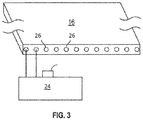
- the monitoring system 24 is electrically connected to one or more tension members 26 of the support structure 16. Although described below with respect to tension members 26, the monitoring system 24 could be connected to one or more strands or individual wires of the tension members 26.
- the monitoring system 24 is connected to support structure 16 at a suitable location, for example, at an end of the support structure 16 located at an upper end of the hoistway of the elevator system 10. It is to be appreciated, though, that this location is merely exemplary and other locations for connecting the monitoring system 24 to the support structure 16 are contemplated within the scope of the present disclosure.
- an electrical current is applied through the tension members 26.
- a resulting voltage allows for determination of an electrical resistance of the tension member 26.
- This measured resistance is compared to an initial resistance of the tension member 26 measured or established during the initial installation of the support structure 16 to the elevator system 10.
- the change in electrical resistance is compared to one or more thresholds, and when the threshold is exceeded, action may be taken by the elevator system 10, including but not limited to, notifying the maintenance provider, sounding of an alarm, and/or stopping operation of the elevator system 10.
- wear of the tension member 26 depends of the traffic pattern of the elevator car 12 along the hoistway 36, for example, cycles of passage of portions of the tension member 26 over the traction sheave 18.
- the monitoring system 24 utilizes an actual traffic pattern of the elevator car 12. Utilization of the actual traffic pattern of the elevator car 12 when determining the resistance threshold allows for a more accurate and less conservative determination of the resistance threshold, thereby potentially extending the useful service life of the support structure 16, compared to a traditional measurement system in which does not take into account an actual traffic pattern of the elevator car. Such a determination results in a more conservative estimation, and thus support structures 16 may be retired from service prior to their useful service life being exhausted.
- the actual traffic pattern is determined via intercommunication between the monitoring system 24 and other components of the elevator system 10.
- the main controller 22 may count quantities of starts at each floor landing 38 of the hoistway 36. Each start at a particular floor landing 38 equates with a passage of a particular portion of the support structure 16 over the traction sheave 18 of the elevator system 10.
- the monitoring system 24 may be connected to a load weight sensor 40 of the elevator car 12, with the sensed load weights being indicative of tensile loads on the support structure 16, in particular a suspension portion 42 of the support structure 16 between the traction sheave 18 and the elevator car 12.
- an elevator system 10 in particular evaluating a condition of the support structure 16, is illustrated.
- the support structure 16 and monitoring system 24 are installed in the hoistway 36.
- an electrical resistance of at least one tension member 26 of the support structure is measured by the monitoring system 24.
- an electrical resistance threshold is established based on an actual traffic pattern of operation of the elevator system 10. In some embodiments, the actual traffic pattern is determined via communication between the monitoring system 24 and the main controller 22 and/or the load weight sensor 40.
- the measured electrical resistance is compared to the electrical resistance threshold, with the result of the comparison indicative of wear of the at least one tension member 26.
- the elevator system 10 is operated for a selected time interval, for example one month or one year.
- the stated time intervals are merely exemplary, however, and other time intervals may be utilized.
- the electrical resistance is remeasured at block 102, and the actual traffic pattern of operation of the elevator system 10 over the time interval may be utilized to modify the electrical resistance threshold at block 104.
- the electrical resistance of the support structure 16 may be measured at measurement intervals that vary over the service life of the support structure.
- the measured electrical resistance is compared to the electrical resistance threshold at block 106 and if the measured electrical resistance exceeds the resistance threshold, the support structure 16 is evaluated further at block 110 for further action, which may include, for example, remeasurement of the electrical resistance, or repair or replacement of the support structure 16. If the measured electrical resistance of the support structure 16 does not exceed the resistance threshold, the elevator system 10 is again operated for a selected interval at block 108. It is to be appreciated that the selected interval may remain constant, or alternatively may change relative to previous selected intervals. For example, early in the life of the support structure 16, the selected interval may be relatively long, and may decrease when the support structure 16 nears its projected end of service life.
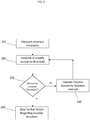
- an electrical resistance of at least one tension member 26 of the support structure is measured by the monitoring system 24.
- an electrical resistance threshold is established based on an actual traffic pattern of operation of the elevator system 10. In some embodiments, the actual traffic pattern is determined via communication between the monitoring system 24 and the main controller 22 and/or the load weight sensor 40.
- the measured electrical resistance is compared to the electrical resistance threshold, with the result of the comparison indicative of wear of the at least one tension member 26.
- the elevator system 10 is operated for a selected time interval, for example one month or one year.
- the stated time intervals are merely exemplary, however, and other time intervals may be utilized.
- the electrical resistance is remeasured at block 202, and the actual traffic pattern of operation of the elevator system 10 over the time interval may be utilized to modify the electrical resistance threshold at block 204.
- the electrical resistance of the support structure 16 may be measured at measurement intervals that vary over the service life of the support structure.
- the measured electrical resistance is compared to the electrical resistance threshold at block 206 and if the measured electrical resistance exceeds the resistance threshold, the support structure 16 is evaluated further at block 210 for further action, which may include, for example, remeasurement of the electrical resistance, or repair or replacement of the support structure 16. If the measured electrical resistance of the support structure 16 does not exceed the resistance threshold, the elevator system 10 is again operated for a selected interval at block 208. It is to be appreciated that the selected interval may remain constant, or alternatively may change relative to previous selected intervals. For example, early in the life of the support structure 16, the selected interval may be relatively long, and may decrease when the support structure 16 nears its projected end of service life.
Landscapes
- Engineering & Computer Science (AREA)
- Automation & Control Theory (AREA)
- Structural Engineering (AREA)
- Mechanical Engineering (AREA)
- Computer Networks & Wireless Communication (AREA)
- Maintenance And Inspection Apparatuses For Elevators (AREA)
- Indicating And Signalling Devices For Elevators (AREA)
Abstract
Description
- Exemplary embodiments generally relates to monitoring systems and methods, and more particularly, to systems and methods for monitoring the condition of a support structure, for example a belt or rope used in an elevator system.
- Tensile support structures, such as coated steel belts or wire ropes containing metal cords, are used to move an elevator car up and down within an elevator shaft or hoistway. Because the condition of the tensile support structure is critical to the safety of the operation of the elevator, there is a need to determine the remaining strength level of the tensile support and detect if the remaining strength level falls below a minimum threshold.
- The strength of a tensile support structure can be reduced by normal operation of the elevator over time. The primary source of the degradation in the strength of the support structure is the cyclic bending of the support structure around sheaves as the elevator is moved up and down in an elevator shaft or hoistway. The degradation of a support structure is normally not uniform along the length of the support structure, but rather, focused to areas of the support structure that are subjected to high levels or severities of bending cycles.
- Some electrical characteristics, such as electrical resistance or impedance, of the cables, cords or tension members in the support structure will vary as the cross-sectional areas of the tension members decrease. Accordingly, it is possible to determine the remaining support strength of the support structure based on the electrical characteristics of the tension members thereof. There currently are some monitoring systems which employ a resistance-based inspection scheme to monitor the resistance of support structures, and thus, the remaining strength thereof. In such systems, a measured electrical resistance is compared to a predetermined resistance threshold such that if the resistance threshold is exceeded, the belt is evaluated for potential repair or replacement. The resistance threshold is determined taking selected factors into account, including an expected elevator system traffic pattern,
- In one embodiment, a method of wear detection of a supporting structure of an elevator system includes measuring an electrical resistance of at least one tension member of a supporting structure via a monitoring system, the supporting structure operably connected to an elevator car and one or more sheaves of an elevator system. A threshold resistance is determined utilizing one or more indicators of an actual traffic pattern of the elevator car. The measured electrical resistance is compared to the threshold resistance, the result of the comparison indicative of wear of the at least one tension member.
- Additionally or alternatively, in this or other embodiments the one or more indicators includes a count of elevator car starts from a selected landing floor of the elevator system.
- Additionally or alternatively, in this or other embodiments the monitoring system may be operably connected to a main controller of the elevator system, the main controller providing the count to the monitoring system.
- Additionally or alternatively, in this or other embodiments the one or more indicators may include load weight data of the elevator car.
- Additionally or alternatively, in this or other embodiments the monitoring system may be operably connected to a load weight sensor of the elevator car to provide the load weight data to the monitoring system.
- Additionally or alternatively, in this or other embodiments the threshold resistance may be re-determined at one or more selected intervals.
- Additionally or alternatively, in this or other embodiments the selected interval may change over a service life of the support structure.
- Additionally or alternatively, in this or other embodiments the electrical resistance may be remeasured at one or more selected measurement intervals.
- Additionally or alternatively, in this or other embodiments the method may include one or more of remeasuring the electrical resistance, repairing the support structure or retiring the support structure if the measured electrical resistance exceeds the resistance threshold.
- In another embodiment, a monitoring system for a support structure of an elevator car of an elevator system includes a monitoring unit engagable to one or more tension members of the support structure and configured to measure an electrical resistance thereof and compare the measured electrical resistance to a threshold resistance. The monitoring unit is operably connected to one or more elevator system components and is configured to determine the threshold resistance utilizing one or more indicators of an actual traffic pattern of the elevator car.
- Additionally or alternatively, in this or other embodiments the one or more indicators may include a count of elevator car starts from a selected landing floor of the elevator system.
- Additionally or alternatively, in this or other embodiments the monitoring system may be operably connected to a main controller of the elevator system, the main controller providing the count to the monitoring system.
- Additionally or alternatively, in this or other embodiments the one or more indicators may include load weight data of the elevator car.
- Additionally or alternatively, in this or other embodiments the monitoring system may be operably connected to a load weight sensor of the elevator car to provide the load weight data to the monitoring system.
- Additionally or alternatively, in this or other embodiments the monitoring unit may be configured to redetermine the threshold resistance at one or more selected intervals.
- Additionally or alternatively, in this or other embodiments the selected interval may change over a service life of the support structure.
- Additionally or alternatively, in this or other embodiments the measurement unit may be configured to remeasure the electrical resistance at one or more selected measurement intervals.
- In yet another embodiment, an elevator system includes an elevator car, a support structure operably connected to the elevator car and configured to move the elevator car along a hoistway of the elevator system, and a monitoring system including a monitoring unit engagable to one or more tension members of the support structure and configured to measure an electrical resistance thereof and compare the measured electrical resistance to a threshold resistance. The monitoring unit is operably connected to one or more elevator system components and is configured to determine the threshold utilizing one or more indicators of an actual traffic pattern of the elevator car.
- Additionally or alternatively, in this or other embodiments the one or more indicators may include one or more of a count of elevator car starts from a selected landing floor of the elevator system, or load weight data of the elevator car.
- Additionally or alternatively, in this or other embodiments the support structure may be one of a rope or a belt.
- The following descriptions should not be considered limiting in any way. With reference to the accompanying drawings, like elements are numbered alike:
-
FIG. 1 is a schematic view of an embodiment of an elevator system; -
FIG. 2A is an end view of an embodiment of a support structure for an elevator system; -
FIG. 2B is a plan view of an embodiment of a support structure for an elevator system; -
FIG. 3 is a schematic illustration of an embodiment of a monitoring system operably connected to a support structure; -
FIG. 4 is an illustration of a method of monitoring a support structure; and -
FIG. 5 is an illustration of another method of monitoring a support structure. - A detailed description of one or more embodiments of the disclosed apparatus and method are presented herein by way of exemplification and not limitation with reference to the Figures.
- The present invention relates to monitoring of support structures. While
FIG. 1 describes one possible support structure, in particular a tensile support structure, namely belts or ropes used to suspend and/or drive components of an elevator system, the present invention could be used with other support structures. Other exemplary support structures include belts or jacketed cords as used in exercise machines, jacketed cables as used with cranes, or any other multistrand wire or rope being used in tension. Referring now toFIG. 1 , anelevator system 10 is shown in schematic fashion. It is to be understood that the version of the elevator system10 shown inFIG. 1 is for illustrative purposes only and to present background for the various components of a general elevator system. - As shown in
FIG. 1 , theelevator system 10 may include a car 12 coupled to acounterweight 14 by asupport structure 16. Thesupport structure 16 may extend over atraction sheave 18 that is driven by amachine 20. Traction between thesheave 18 and thesupport structure 16 may drive the car 12 andcounterweight 14 through the hoistway. Operation of themachine 20 may be controlled by amain controller 22. Theelevator system 10 may further include amonitoring system 24 in electrical communication with, and/or disposed in a location proximate to, thesupport structure 16 and configured to detect the condition of thesupport structure 16 by measuring, for example continuously or intermittently, the resistance thereof. - Turning to
FIG. 2A , oneexemplary support structure 16 is provided in the form of a belt having a plurality ofindividual tension members 26 in ajacket coating 28. Thetension members 26 may include conventional steel wires formed into strands and/or cords, or any other supportive material having an electrical resistance. Thejacket coating 28 may comprise one or more materials suitable for promoting traction with thetraction sheave 18, such as polyurethane or elastomeric materials. Thejacket coating 28 may additionally comprise an electrically insulative material suitable for prohibiting electrical communication therein. The operational condition or state of one or more (including each)tension member 26 of thesupport structure 16 ofFIG. 2A may be determined using a resistance-based inspection scheme, wherein, for example, the remaining life of the one ormore tension members 26 of thesupport structure 16 may be determined in terms of the increase in the resistance of thetension members 26 relative to a baseline value (for example measured during initial installation of thesupport structure 16 in theelevator system 10. The overall operational condition or state of asupport structure 16 could be monitored continuously or intermittently for any substantial increase in resistance. Thesupport structure 16 may also be monitored for any wear in thejacket coating 28 by, for example, detecting for any contact or electrical short betweenexposed tension members 26 and electrically conductive idler or fraction sheaves 18. In one possible arrangement, theindividual tension members 26 may be connected in series so as to minimize the number of monitored resistances and provide one effective resistance persupport structure 16. The effective resistance of asupport structure 16 may be indicative of the actual resistance, or any multiple, fraction or scale thereof, exhibited by the support structure 16.As shown by the ends of anexemplary support structure 16 ofFIG. 2B , thetension members 26 may be coupled or shorted together at alternating and respectiveends using connectors 30 so as to electrically connect thetension members 26 associated with onesupport structure 16 in series form. Other arrangements, such as monitoring one ormore tension members 26 in parallel or a combination of parallel and serial monitoring of subsets of thetension members 26, are also possible. - Referring to
FIG. 3 , themonitoring system 24 is electrically connected to one ormore tension members 26 of thesupport structure 16. Although described below with respect totension members 26, themonitoring system 24 could be connected to one or more strands or individual wires of thetension members 26. Themonitoring system 24 is connected to supportstructure 16 at a suitable location, for example, at an end of thesupport structure 16 located at an upper end of the hoistway of theelevator system 10. It is to be appreciated, though, that this location is merely exemplary and other locations for connecting themonitoring system 24 to thesupport structure 16 are contemplated within the scope of the present disclosure. - During operation, an electrical current is applied through the
tension members 26. A resulting voltage allows for determination of an electrical resistance of thetension member 26. This measured resistance is compared to an initial resistance of thetension member 26 measured or established during the initial installation of thesupport structure 16 to theelevator system 10. A change in the electrical resistance of thetension member 26, typically an increase in resistance, indicates wear of thetension member 26. The change in electrical resistance is compared to one or more thresholds, and when the threshold is exceeded, action may be taken by theelevator system 10, including but not limited to, notifying the maintenance provider, sounding of an alarm, and/or stopping operation of theelevator system 10. - Referring again to
FIG. 1 , wear of thetension member 26 depends of the traffic pattern of the elevator car 12 along thehoistway 36, for example, cycles of passage of portions of thetension member 26 over thetraction sheave 18. As such, when determining the resistance threshold, themonitoring system 24 utilizes an actual traffic pattern of the elevator car 12. Utilization of the actual traffic pattern of the elevator car 12 when determining the resistance threshold allows for a more accurate and less conservative determination of the resistance threshold, thereby potentially extending the useful service life of thesupport structure 16, compared to a traditional measurement system in which does not take into account an actual traffic pattern of the elevator car. Such a determination results in a more conservative estimation, and thus supportstructures 16 may be retired from service prior to their useful service life being exhausted. - The actual traffic pattern is determined via intercommunication between the
monitoring system 24 and other components of theelevator system 10. For example, themain controller 22 may count quantities of starts at each floor landing 38 of thehoistway 36. Each start at a particular floor landing 38 equates with a passage of a particular portion of thesupport structure 16 over thetraction sheave 18 of theelevator system 10. Further, themonitoring system 24 may be connected to aload weight sensor 40 of the elevator car 12, with the sensed load weights being indicative of tensile loads on thesupport structure 16, in particular asuspension portion 42 of thesupport structure 16 between thetraction sheave 18 and the elevator car 12. - Referring now to
FIG. 4 , a method of operating anelevator system 10, in particular evaluating a condition of thesupport structure 16, is illustrated. Inblock 100, thesupport structure 16 andmonitoring system 24 are installed in thehoistway 36. Atblock 102, an electrical resistance of at least onetension member 26 of the support structure is measured by themonitoring system 24. Atblock 104, an electrical resistance threshold is established based on an actual traffic pattern of operation of theelevator system 10. In some embodiments, the actual traffic pattern is determined via communication between themonitoring system 24 and themain controller 22 and/or theload weight sensor 40. Atblock 106, the measured electrical resistance is compared to the electrical resistance threshold, with the result of the comparison indicative of wear of the at least onetension member 26. - If the measured electrical resistance is below the electrical resistance threshold, at
block 108 theelevator system 10 is operated for a selected time interval, for example one month or one year. The stated time intervals are merely exemplary, however, and other time intervals may be utilized. When the time interval is complete, the electrical resistance is remeasured atblock 102, and the actual traffic pattern of operation of theelevator system 10 over the time interval may be utilized to modify the electrical resistance threshold atblock 104. One skilled in the art will readily appreciate that the electrical resistance of thesupport structure 16 may be measured at measurement intervals that vary over the service life of the support structure. The measured electrical resistance is compared to the electrical resistance threshold atblock 106 and if the measured electrical resistance exceeds the resistance threshold, thesupport structure 16 is evaluated further atblock 110 for further action, which may include, for example, remeasurement of the electrical resistance, or repair or replacement of thesupport structure 16. If the measured electrical resistance of thesupport structure 16 does not exceed the resistance threshold, theelevator system 10 is again operated for a selected interval atblock 108. It is to be appreciated that the selected interval may remain constant, or alternatively may change relative to previous selected intervals. For example, early in the life of thesupport structure 16, the selected interval may be relatively long, and may decrease when thesupport structure 16 nears its projected end of service life. - Referring now to
FIG. 5 , a method of wear detection of thesupport structure 16 is illustrated. Atblock 202, an electrical resistance of at least onetension member 26 of the support structure is measured by themonitoring system 24. Atblock 204, an electrical resistance threshold is established based on an actual traffic pattern of operation of theelevator system 10. In some embodiments, the actual traffic pattern is determined via communication between themonitoring system 24 and themain controller 22 and/or theload weight sensor 40. Atblock 206, the measured electrical resistance is compared to the electrical resistance threshold, with the result of the comparison indicative of wear of the at least onetension member 26. - If the measured electrical resistance is below the electrical resistance threshold, at
block 208 theelevator system 10 is operated for a selected time interval, for example one month or one year. The stated time intervals are merely exemplary, however, and other time intervals may be utilized. When the time interval is complete, the electrical resistance is remeasured atblock 202, and the actual traffic pattern of operation of theelevator system 10 over the time interval may be utilized to modify the electrical resistance threshold atblock 204. One skilled in the art will readily appreciate that the electrical resistance of thesupport structure 16 may be measured at measurement intervals that vary over the service life of the support structure. The measured electrical resistance is compared to the electrical resistance threshold atblock 206 and if the measured electrical resistance exceeds the resistance threshold, thesupport structure 16 is evaluated further atblock 210 for further action, which may include, for example, remeasurement of the electrical resistance, or repair or replacement of thesupport structure 16. If the measured electrical resistance of thesupport structure 16 does not exceed the resistance threshold, theelevator system 10 is again operated for a selected interval atblock 208. It is to be appreciated that the selected interval may remain constant, or alternatively may change relative to previous selected intervals. For example, early in the life of thesupport structure 16, the selected interval may be relatively long, and may decrease when thesupport structure 16 nears its projected end of service life. - Utilizing actual traffic patterns of operation of the
elevator system 10 in determination of the resistance threshold for use in electrical resistance-based evaluation of thesupport structure 16, reduces uncertainty in establishing the resistance threshold, thus extending useful service life of thesupport structure 16 and reducing associated costs and maintenance time. - The term "about" is intended to include the degree of error associated with measurement of the particular quantity based upon the equipment available at the time of filing the application.
- The terminology used herein is for the purpose of describing particular embodiments only and is not intended to be limiting of the present disclosure. As used herein, the singular forms "a", "an" and "the" are intended to include the plural forms as well, unless the context clearly indicates otherwise. It will be further understood that the terms "comprises" and/or "comprising," when used in this specification, specify the presence of stated features, integers, steps, operations, elements, and/or components, but do not preclude the presence or addition of one or more other features, integers, steps, operations, element components, and/or groups thereof.
- While the present disclosure has been described with reference to an exemplary embodiment or embodiments, it will be understood by those skilled in the art that various changes may be made and equivalents may be substituted for elements thereof without departing from the scope of the present disclosure. In addition, many modifications may be made to adapt a particular situation or material to the teachings of the present disclosure without departing from the essential scope thereof. Therefore, it is intended that the present disclosure not be limited to the particular embodiment disclosed as the best mode contemplated for carrying out this present disclosure, but that the present disclosure will include all embodiments falling within the scope of the claims.
Claims (15)
- A method of wear detection of a supporting structure of an elevator system, comprising:measuring an electrical resistance of at least one tension member of a supporting structure via a monitoring system, the supporting structure being operably connected to an elevator car and one or more sheaves of an elevator system;determining a threshold resistance utilizing one or more indicators of an actual traffic pattern of the elevator car; andcomparing the measured electrical resistance to the threshold resistance, the result of the comparison indicative of wear of the at least one tension member.
- The method of any of the preceding claims, wherein the one or more indicators includes a count of elevator car starts from a selected landing floor of the elevator system.
- The method of any of the preceding claims, wherein the monitoring system is operably connected to a main controller of the elevator system, the main controller providing the count to the monitoring system.
- The method of any of the preceding claims, wherein the one or more indicators includes load weight data of the elevator car.
- The method of any of the preceding claims, wherein the monitoring system is operably connected to a load weight sensor of the elevator car to provide the load weight data to the monitoring system.
- The method of any of the preceding claims 1, wherein the threshold resistance is re-determined at one or more selected intervals,
wherein the selected interval preferably changes over a service life of the support structure. - The method of any of the preceding claims, wherein the electrical resistance is remeasured at one or more selected measurement intervals.
- The method of any of the preceding claims, further comprising one or more of the following steps: remeasuring the electrical resistance; repairing the support structure; or retiring the support structure if the measured electrical resistance exceeds the resistance threshold.
- A monitoring system for a support structure of an elevator car of an elevator system, the monitoring system comprising a monitoring unit engagable to one or more tension members of the support structure, and operably connected to one or more elevator system components,
wherein the monitoring unit is configured todetermine the threshold resistance utilizing one or more indicators of an actual traffic pattern of the elevator car, andmeasure an electrical resistance of the one or more tension members, andcompare the measured electrical resistance to a threshold resistance. - The monitoring system of claim 9, wherein the one or more indicators includes: a count of elevator car starts from a selected landing floor of the elevator system or load weight data of the elevator car.
- The monitoring system of claim 9 or 10, wherein the monitoring system is operably connected to a main controller of the elevator system, the main controller providing the count to the monitoring system.
- The monitoring system of claim any of claims 9 to 11, wherein the one or more indicators includes load weight data of the elevator car,
wherein preferably the monitoring system is operably connected to a load weight sensor of the elevator car to provide the load weight data to the monitoring system. - The monitoring system of any of claims 9 to 12, wherein the monitoring unit is configured to redetermine the threshold resistance at one or more selected intervals,
wherein preferably the selected interval changes over a service life of the support structure. - The monitoring system of any of claims 9 to 14, wherein the measurement unit is configured to remeasure the electrical resistance at one or more selected measurement intervals.
- An elevator system, comprising:an elevator car;a support structure operably connected to the elevator car and configured to move the elevator car along a hoistway of the elevator system; anda monitoring system according to any of claims 9 to 14,wherein the support structure is preferably one of a rope or a belt.
Applications Claiming Priority (1)
| Application Number | Priority Date | Filing Date | Title |
|---|---|---|---|
| US16/164,146 US20200122973A1 (en) | 2018-10-18 | 2018-10-18 | Resistance-based inspection of elevator system support members |
Publications (2)
| Publication Number | Publication Date |
|---|---|
| EP3640189A1 true EP3640189A1 (en) | 2020-04-22 |
| EP3640189B1 EP3640189B1 (en) | 2025-01-29 |
Family
ID=68242393
Family Applications (1)
| Application Number | Title | Priority Date | Filing Date |
|---|---|---|---|
| EP19202078.2A Active EP3640189B1 (en) | 2018-10-18 | 2019-10-08 | Resistance-based inspection of elevator system support members |
Country Status (4)
| Country | Link |
|---|---|
| US (1) | US20200122973A1 (en) |
| EP (1) | EP3640189B1 (en) |
| CN (1) | CN111071897A (en) |
| ES (1) | ES3010257T3 (en) |
Cited By (1)
| Publication number | Priority date | Publication date | Assignee | Title |
|---|---|---|---|---|
| EP4378876A1 (en) * | 2022-11-29 | 2024-06-05 | Otis Elevator Company | Elevator suspension member monitoring |
Families Citing this family (3)
| Publication number | Priority date | Publication date | Assignee | Title |
|---|---|---|---|---|
| US20190100408A1 (en) * | 2017-09-29 | 2019-04-04 | Otis Elevator Company | Rope deterioration detection |
| US20210339984A1 (en) * | 2020-04-29 | 2021-11-04 | Tk Elevator Innovation And Operations Gmbh | Methods of monitoring the condition of elevator belts |
| CN113945448B (en) * | 2021-09-30 | 2023-06-30 | 厦门市特种设备检验检测院 | Elevator door bearing strength detector |
Citations (4)
| Publication number | Priority date | Publication date | Assignee | Title |
|---|---|---|---|---|
| WO2005094250A2 (en) * | 2004-03-16 | 2005-10-13 | Otis Elevator Company | Tensile support strength monitoring system and method |
| WO2005095250A1 (en) * | 2004-03-16 | 2005-10-13 | Otis Elevator Company | Tensile support strength measurement system and method |
| US20130153340A1 (en) * | 2011-12-20 | 2013-06-20 | Inventio Ag | Checking states in an elevator installation |
| EP2749521A2 (en) * | 2012-12-30 | 2014-07-02 | Kone Corporation | A method and an arrangement in rope condition monitoring of an elevator |
Family Cites Families (12)
| Publication number | Priority date | Publication date | Assignee | Title |
|---|---|---|---|---|
| EP1730066B1 (en) * | 2004-03-16 | 2010-10-20 | Otis Elevator Company | Elevator load bearing member wear and failure detection |
| WO2012030332A1 (en) * | 2010-09-01 | 2012-03-08 | Otis Elevator Company | Resistance-based monitoring system and method |
| US9995711B2 (en) * | 2012-04-02 | 2018-06-12 | Otis Elevator Company | Calibration of wear detection system |
| ES2687278T3 (en) * | 2013-11-13 | 2018-10-24 | Kone Corporation | Procedure to monitor the condition of the elevator cables and their arrangement |
| CN106458510A (en) * | 2014-02-18 | 2017-02-22 | 奥的斯电梯公司 | Connector for inspection system of elevator tension member |
| FI126182B (en) * | 2014-06-17 | 2016-07-29 | Kone Corp | Procedure and arrangement for monitoring the condition of a lift line |
| BR112017009860A2 (en) * | 2014-11-28 | 2017-12-19 | Inventio Ag | elevator system |
| US9932203B2 (en) * | 2015-07-31 | 2018-04-03 | Inventio Ag | Method and device for detecting a deterioration state of a load bearing capacity in a suspension member arrangement for an elevator |
| CN107922157B (en) * | 2015-08-21 | 2020-08-04 | 通力股份公司 | Device and method for monitoring the condition of a traction belt and/or a traction belt terminal |
| WO2019066856A1 (en) * | 2017-09-28 | 2019-04-04 | Kone Corporation | A method, an elevator safety control unit, and an elevator system for defining a condition of an elevator car suspension means |
| CN108423521B (en) * | 2018-06-12 | 2019-10-15 | 安徽伟迈信息技术有限公司 | Lift Cable Monitoring System |
| US20210094800A1 (en) * | 2019-09-27 | 2021-04-01 | Thyssenkrupp Elevator Innovation And Operations Gmbh | Systems and methods for monitoring the integrity of belts in elevator systems |
-
2018
- 2018-10-18 US US16/164,146 patent/US20200122973A1/en active Pending
-
2019
- 2019-10-08 EP EP19202078.2A patent/EP3640189B1/en active Active
- 2019-10-08 ES ES19202078T patent/ES3010257T3/en active Active
- 2019-10-17 CN CN201910987247.XA patent/CN111071897A/en active Pending
Patent Citations (4)
| Publication number | Priority date | Publication date | Assignee | Title |
|---|---|---|---|---|
| WO2005094250A2 (en) * | 2004-03-16 | 2005-10-13 | Otis Elevator Company | Tensile support strength monitoring system and method |
| WO2005095250A1 (en) * | 2004-03-16 | 2005-10-13 | Otis Elevator Company | Tensile support strength measurement system and method |
| US20130153340A1 (en) * | 2011-12-20 | 2013-06-20 | Inventio Ag | Checking states in an elevator installation |
| EP2749521A2 (en) * | 2012-12-30 | 2014-07-02 | Kone Corporation | A method and an arrangement in rope condition monitoring of an elevator |
Cited By (1)
| Publication number | Priority date | Publication date | Assignee | Title |
|---|---|---|---|---|
| EP4378876A1 (en) * | 2022-11-29 | 2024-06-05 | Otis Elevator Company | Elevator suspension member monitoring |
Also Published As
| Publication number | Publication date |
|---|---|
| ES3010257T3 (en) | 2025-04-01 |
| US20200122973A1 (en) | 2020-04-23 |
| CN111071897A (en) | 2020-04-28 |
| EP3640189B1 (en) | 2025-01-29 |
Similar Documents
| Publication | Publication Date | Title |
|---|---|---|
| AU2009331700B2 (en) | Method for monitoring an elevator support means, an elevator support means monitoring device, and an elevator system having such a monitoring device | |
| EP3640189B1 (en) | Resistance-based inspection of elevator system support members | |
| US8807286B2 (en) | Method and an arrangement in rope condition monitoring of an elevator | |
| CN106477411B (en) | Method, installation and elevator | |
| EP2611720B1 (en) | Resistance-based monitoring system and method | |
| US9995711B2 (en) | Calibration of wear detection system | |
| US9327941B2 (en) | Method and apparatus for checking states in an elevator installation | |
| JPWO2002046082A1 (en) | Elevator main rope stretch detection device | |
| JP2003112876A (en) | Suspension rope wear detector | |
| CA2890138C (en) | Lift installation | |
| US9828216B2 (en) | Connector for inspection system of elevator tension member | |
| CN107922157A (en) | For leash and/or the apparatus and method for the status monitoring for drawing tape terminal | |
| EP3470357B1 (en) | System and method for monitoring wire ropes | |
| EP3505482B1 (en) | Method for condition monitoring of a rope of a hoisting apparatus | |
| EP3461779A1 (en) | Rope deterioration detection | |
| CN107074488A (en) | elevator equipment | |
| US5886308A (en) | Rope speed monitoring assembly and method | |
| US20190202667A1 (en) | Method and testing device for determining a state of a suspension traction apparatus of an elevator system | |
| EP4516717B1 (en) | Elongation based monitoring of tension members | |
| EP4737375A1 (en) | Resistance-based inspection of elevator system support members | |
| JP2004196449A (en) | elevator | |
| HK1235379A1 (en) | Method, arrangement and elevator |
Legal Events
| Date | Code | Title | Description |
|---|---|---|---|
| PUAI | Public reference made under article 153(3) epc to a published international application that has entered the european phase |
Free format text: ORIGINAL CODE: 0009012 |
|
| STAA | Information on the status of an ep patent application or granted ep patent |
Free format text: STATUS: THE APPLICATION HAS BEEN PUBLISHED |
|
| AK | Designated contracting states |
Kind code of ref document: A1 Designated state(s): AL AT BE BG CH CY CZ DE DK EE ES FI FR GB GR HR HU IE IS IT LI LT LU LV MC MK MT NL NO PL PT RO RS SE SI SK SM TR |
|
| AX | Request for extension of the european patent |
Extension state: BA ME |
|
| STAA | Information on the status of an ep patent application or granted ep patent |
Free format text: STATUS: REQUEST FOR EXAMINATION WAS MADE |
|
| 17P | Request for examination filed |
Effective date: 20200902 |
|
| RBV | Designated contracting states (corrected) |
Designated state(s): AL AT BE BG CH CY CZ DE DK EE ES FI FR GB GR HR HU IE IS IT LI LT LU LV MC MK MT NL NO PL PT RO RS SE SI SK SM TR |
|
| STAA | Information on the status of an ep patent application or granted ep patent |
Free format text: STATUS: EXAMINATION IS IN PROGRESS |
|
| 17Q | First examination report despatched |
Effective date: 20210210 |
|
| GRAP | Despatch of communication of intention to grant a patent |
Free format text: ORIGINAL CODE: EPIDOSNIGR1 |
|
| STAA | Information on the status of an ep patent application or granted ep patent |
Free format text: STATUS: GRANT OF PATENT IS INTENDED |
|
| INTG | Intention to grant announced |
Effective date: 20240902 |
|
| GRAS | Grant fee paid |
Free format text: ORIGINAL CODE: EPIDOSNIGR3 |
|
| GRAA | (expected) grant |
Free format text: ORIGINAL CODE: 0009210 |
|
| STAA | Information on the status of an ep patent application or granted ep patent |
Free format text: STATUS: THE PATENT HAS BEEN GRANTED |
|
| AK | Designated contracting states |
Kind code of ref document: B1 Designated state(s): AL AT BE BG CH CY CZ DE DK EE ES FI FR GB GR HR HU IE IS IT LI LT LU LV MC MK MT NL NO PL PT RO RS SE SI SK SM TR |
|
| REG | Reference to a national code |
Ref country code: GB Ref legal event code: FG4D |
|
| REG | Reference to a national code |
Ref country code: CH Ref legal event code: EP |
|
| REG | Reference to a national code |
Ref country code: DE Ref legal event code: R096 Ref document number: 602019065337 Country of ref document: DE |
|
| REG | Reference to a national code |
Ref country code: IE Ref legal event code: FG4D |
|
| REG | Reference to a national code |
Ref country code: ES Ref legal event code: FG2A Ref document number: 3010257 Country of ref document: ES Kind code of ref document: T3 Effective date: 20250401 |
|
| REG | Reference to a national code |
Ref country code: NL Ref legal event code: MP Effective date: 20250129 |
|
| PG25 | Lapsed in a contracting state [announced via postgrant information from national office to epo] |
Ref country code: NL Free format text: LAPSE BECAUSE OF FAILURE TO SUBMIT A TRANSLATION OF THE DESCRIPTION OR TO PAY THE FEE WITHIN THE PRESCRIBED TIME-LIMIT Effective date: 20250129 |
|
| PG25 | Lapsed in a contracting state [announced via postgrant information from national office to epo] |
Ref country code: RS Free format text: LAPSE BECAUSE OF FAILURE TO SUBMIT A TRANSLATION OF THE DESCRIPTION OR TO PAY THE FEE WITHIN THE PRESCRIBED TIME-LIMIT Effective date: 20250429 |
|
| PG25 | Lapsed in a contracting state [announced via postgrant information from national office to epo] |
Ref country code: FI Free format text: LAPSE BECAUSE OF FAILURE TO SUBMIT A TRANSLATION OF THE DESCRIPTION OR TO PAY THE FEE WITHIN THE PRESCRIBED TIME-LIMIT Effective date: 20250129 |
|
| PG25 | Lapsed in a contracting state [announced via postgrant information from national office to epo] |
Ref country code: PL Free format text: LAPSE BECAUSE OF FAILURE TO SUBMIT A TRANSLATION OF THE DESCRIPTION OR TO PAY THE FEE WITHIN THE PRESCRIBED TIME-LIMIT Effective date: 20250129 |
|
| REG | Reference to a national code |
Ref country code: LT Ref legal event code: MG9D |
|
| PG25 | Lapsed in a contracting state [announced via postgrant information from national office to epo] |
Ref country code: NO Free format text: LAPSE BECAUSE OF FAILURE TO SUBMIT A TRANSLATION OF THE DESCRIPTION OR TO PAY THE FEE WITHIN THE PRESCRIBED TIME-LIMIT Effective date: 20250429 Ref country code: IS Free format text: LAPSE BECAUSE OF FAILURE TO SUBMIT A TRANSLATION OF THE DESCRIPTION OR TO PAY THE FEE WITHIN THE PRESCRIBED TIME-LIMIT Effective date: 20250529 |
|
| REG | Reference to a national code |
Ref country code: AT Ref legal event code: MK05 Ref document number: 1763311 Country of ref document: AT Kind code of ref document: T Effective date: 20250129 |
|
| PG25 | Lapsed in a contracting state [announced via postgrant information from national office to epo] |
Ref country code: HR Free format text: LAPSE BECAUSE OF FAILURE TO SUBMIT A TRANSLATION OF THE DESCRIPTION OR TO PAY THE FEE WITHIN THE PRESCRIBED TIME-LIMIT Effective date: 20250129 |
|
| PG25 | Lapsed in a contracting state [announced via postgrant information from national office to epo] |
Ref country code: PT Free format text: LAPSE BECAUSE OF FAILURE TO SUBMIT A TRANSLATION OF THE DESCRIPTION OR TO PAY THE FEE WITHIN THE PRESCRIBED TIME-LIMIT Effective date: 20250529 Ref country code: LV Free format text: LAPSE BECAUSE OF FAILURE TO SUBMIT A TRANSLATION OF THE DESCRIPTION OR TO PAY THE FEE WITHIN THE PRESCRIBED TIME-LIMIT Effective date: 20250129 |
|
| PG25 | Lapsed in a contracting state [announced via postgrant information from national office to epo] |
Ref country code: GR Free format text: LAPSE BECAUSE OF FAILURE TO SUBMIT A TRANSLATION OF THE DESCRIPTION OR TO PAY THE FEE WITHIN THE PRESCRIBED TIME-LIMIT Effective date: 20250430 Ref country code: BG Free format text: LAPSE BECAUSE OF FAILURE TO SUBMIT A TRANSLATION OF THE DESCRIPTION OR TO PAY THE FEE WITHIN THE PRESCRIBED TIME-LIMIT Effective date: 20250129 |
|
| PG25 | Lapsed in a contracting state [announced via postgrant information from national office to epo] |
Ref country code: AT Free format text: LAPSE BECAUSE OF FAILURE TO SUBMIT A TRANSLATION OF THE DESCRIPTION OR TO PAY THE FEE WITHIN THE PRESCRIBED TIME-LIMIT Effective date: 20250129 |
|
| PG25 | Lapsed in a contracting state [announced via postgrant information from national office to epo] |
Ref country code: SE Free format text: LAPSE BECAUSE OF FAILURE TO SUBMIT A TRANSLATION OF THE DESCRIPTION OR TO PAY THE FEE WITHIN THE PRESCRIBED TIME-LIMIT Effective date: 20250129 |
|
| PG25 | Lapsed in a contracting state [announced via postgrant information from national office to epo] |
Ref country code: SM Free format text: LAPSE BECAUSE OF FAILURE TO SUBMIT A TRANSLATION OF THE DESCRIPTION OR TO PAY THE FEE WITHIN THE PRESCRIBED TIME-LIMIT Effective date: 20250129 |
|
| PG25 | Lapsed in a contracting state [announced via postgrant information from national office to epo] |
Ref country code: DK Free format text: LAPSE BECAUSE OF FAILURE TO SUBMIT A TRANSLATION OF THE DESCRIPTION OR TO PAY THE FEE WITHIN THE PRESCRIBED TIME-LIMIT Effective date: 20250129 |
|
| PG25 | Lapsed in a contracting state [announced via postgrant information from national office to epo] |
Ref country code: IT Free format text: LAPSE BECAUSE OF FAILURE TO SUBMIT A TRANSLATION OF THE DESCRIPTION OR TO PAY THE FEE WITHIN THE PRESCRIBED TIME-LIMIT Effective date: 20250129 |
|
| PGFP | Annual fee paid to national office [announced via postgrant information from national office to epo] |
Ref country code: GB Payment date: 20250923 Year of fee payment: 7 |
|
| PGFP | Annual fee paid to national office [announced via postgrant information from national office to epo] |
Ref country code: FR Payment date: 20250923 Year of fee payment: 7 |
|
| PG25 | Lapsed in a contracting state [announced via postgrant information from national office to epo] |
Ref country code: EE Free format text: LAPSE BECAUSE OF FAILURE TO SUBMIT A TRANSLATION OF THE DESCRIPTION OR TO PAY THE FEE WITHIN THE PRESCRIBED TIME-LIMIT Effective date: 20250129 Ref country code: CZ Free format text: LAPSE BECAUSE OF FAILURE TO SUBMIT A TRANSLATION OF THE DESCRIPTION OR TO PAY THE FEE WITHIN THE PRESCRIBED TIME-LIMIT Effective date: 20250129 |
|
| PG25 | Lapsed in a contracting state [announced via postgrant information from national office to epo] |
Ref country code: RO Free format text: LAPSE BECAUSE OF FAILURE TO SUBMIT A TRANSLATION OF THE DESCRIPTION OR TO PAY THE FEE WITHIN THE PRESCRIBED TIME-LIMIT Effective date: 20250129 |
|
| PG25 | Lapsed in a contracting state [announced via postgrant information from national office to epo] |
Ref country code: SK Free format text: LAPSE BECAUSE OF FAILURE TO SUBMIT A TRANSLATION OF THE DESCRIPTION OR TO PAY THE FEE WITHIN THE PRESCRIBED TIME-LIMIT Effective date: 20250129 |
|
| REG | Reference to a national code |
Ref country code: DE Ref legal event code: R097 Ref document number: 602019065337 Country of ref document: DE |
|
| PLBE | No opposition filed within time limit |
Free format text: ORIGINAL CODE: 0009261 |
|
| STAA | Information on the status of an ep patent application or granted ep patent |
Free format text: STATUS: NO OPPOSITION FILED WITHIN TIME LIMIT |
|
| 26N | No opposition filed |
Effective date: 20251030 |
|
| PGFP | Annual fee paid to national office [announced via postgrant information from national office to epo] |
Ref country code: DE Payment date: 20250923 Year of fee payment: 7 |
|
| PGFP | Annual fee paid to national office [announced via postgrant information from national office to epo] |
Ref country code: ES Payment date: 20251103 Year of fee payment: 7 |