EP3640153A1 - Packaging container and method for manufacturing same - Google Patents
Packaging container and method for manufacturing same Download PDFInfo
- Publication number
- EP3640153A1 EP3640153A1 EP18818554.0A EP18818554A EP3640153A1 EP 3640153 A1 EP3640153 A1 EP 3640153A1 EP 18818554 A EP18818554 A EP 18818554A EP 3640153 A1 EP3640153 A1 EP 3640153A1
- Authority
- EP
- European Patent Office
- Prior art keywords
- surface portion
- area
- front surface
- packaging container
- rear surface
- Prior art date
- Legal status (The legal status is an assumption and is not a legal conclusion. Google has not performed a legal analysis and makes no representation as to the accuracy of the status listed.)
- Granted
Links
Images



Classifications
-
- B—PERFORMING OPERATIONS; TRANSPORTING
- B65—CONVEYING; PACKING; STORING; HANDLING THIN OR FILAMENTARY MATERIAL
- B65D—CONTAINERS FOR STORAGE OR TRANSPORT OF ARTICLES OR MATERIALS, e.g. BAGS, BARRELS, BOTTLES, BOXES, CANS, CARTONS, CRATES, DRUMS, JARS, TANKS, HOPPERS, FORWARDING CONTAINERS; ACCESSORIES, CLOSURES, OR FITTINGS THEREFOR; PACKAGING ELEMENTS; PACKAGES
- B65D75/00—Packages comprising articles or materials partially or wholly enclosed in strips, sheets, blanks, tubes or webs of flexible sheet material, e.g. in folded wrappers
- B65D75/008—Standing pouches, i.e. "Standbeutel"
-
- B—PERFORMING OPERATIONS; TRANSPORTING
- B31—MAKING ARTICLES OF PAPER, CARDBOARD OR MATERIAL WORKED IN A MANNER ANALOGOUS TO PAPER; WORKING PAPER, CARDBOARD OR MATERIAL WORKED IN A MANNER ANALOGOUS TO PAPER
- B31B—MAKING CONTAINERS OF PAPER, CARDBOARD OR MATERIAL WORKED IN A MANNER ANALOGOUS TO PAPER
- B31B70/00—Making flexible containers, e.g. envelopes or bags
- B31B70/26—Folding sheets, blanks or webs
-
- B—PERFORMING OPERATIONS; TRANSPORTING
- B31—MAKING ARTICLES OF PAPER, CARDBOARD OR MATERIAL WORKED IN A MANNER ANALOGOUS TO PAPER; WORKING PAPER, CARDBOARD OR MATERIAL WORKED IN A MANNER ANALOGOUS TO PAPER
- B31B—MAKING CONTAINERS OF PAPER, CARDBOARD OR MATERIAL WORKED IN A MANNER ANALOGOUS TO PAPER
- B31B70/00—Making flexible containers, e.g. envelopes or bags
- B31B70/60—Uniting opposed surfaces or edges; Taping
- B31B70/64—Uniting opposed surfaces or edges; Taping by applying heat or pressure
-
- B—PERFORMING OPERATIONS; TRANSPORTING
- B31—MAKING ARTICLES OF PAPER, CARDBOARD OR MATERIAL WORKED IN A MANNER ANALOGOUS TO PAPER; WORKING PAPER, CARDBOARD OR MATERIAL WORKED IN A MANNER ANALOGOUS TO PAPER
- B31B—MAKING CONTAINERS OF PAPER, CARDBOARD OR MATERIAL WORKED IN A MANNER ANALOGOUS TO PAPER
- B31B70/00—Making flexible containers, e.g. envelopes or bags
- B31B70/74—Auxiliary operations
- B31B70/79—Coating; Impregnating; Waterproofing; Decoating
-
- B—PERFORMING OPERATIONS; TRANSPORTING
- B32—LAYERED PRODUCTS
- B32B—LAYERED PRODUCTS, i.e. PRODUCTS BUILT-UP OF STRATA OF FLAT OR NON-FLAT, e.g. CELLULAR OR HONEYCOMB, FORM
- B32B27/00—Layered products comprising a layer of synthetic resin
- B32B27/06—Layered products comprising a layer of synthetic resin as the main or only constituent of a layer, which is next to another layer of the same or of a different material
- B32B27/10—Layered products comprising a layer of synthetic resin as the main or only constituent of a layer, which is next to another layer of the same or of a different material of paper or cardboard
-
- B—PERFORMING OPERATIONS; TRANSPORTING
- B32—LAYERED PRODUCTS
- B32B—LAYERED PRODUCTS, i.e. PRODUCTS BUILT-UP OF STRATA OF FLAT OR NON-FLAT, e.g. CELLULAR OR HONEYCOMB, FORM
- B32B27/00—Layered products comprising a layer of synthetic resin
- B32B27/32—Layered products comprising a layer of synthetic resin comprising polyolefins
-
- B—PERFORMING OPERATIONS; TRANSPORTING
- B32—LAYERED PRODUCTS
- B32B—LAYERED PRODUCTS, i.e. PRODUCTS BUILT-UP OF STRATA OF FLAT OR NON-FLAT, e.g. CELLULAR OR HONEYCOMB, FORM
- B32B29/00—Layered products comprising a layer of paper or cardboard
- B32B29/002—Layered products comprising a layer of paper or cardboard as the main or only constituent of a layer, which is next to another layer of the same or of a different material
-
- B—PERFORMING OPERATIONS; TRANSPORTING
- B65—CONVEYING; PACKING; STORING; HANDLING THIN OR FILAMENTARY MATERIAL
- B65D—CONTAINERS FOR STORAGE OR TRANSPORT OF ARTICLES OR MATERIALS, e.g. BAGS, BARRELS, BOTTLES, BOXES, CANS, CARTONS, CRATES, DRUMS, JARS, TANKS, HOPPERS, FORWARDING CONTAINERS; ACCESSORIES, CLOSURES, OR FITTINGS THEREFOR; PACKAGING ELEMENTS; PACKAGES
- B65D65/00—Wrappers or flexible covers; Packaging materials of special type or form
- B65D65/38—Packaging materials of special type or form
- B65D65/40—Applications of laminates for particular packaging purposes
-
- B—PERFORMING OPERATIONS; TRANSPORTING
- B65—CONVEYING; PACKING; STORING; HANDLING THIN OR FILAMENTARY MATERIAL
- B65D—CONTAINERS FOR STORAGE OR TRANSPORT OF ARTICLES OR MATERIALS, e.g. BAGS, BARRELS, BOTTLES, BOXES, CANS, CARTONS, CRATES, DRUMS, JARS, TANKS, HOPPERS, FORWARDING CONTAINERS; ACCESSORIES, CLOSURES, OR FITTINGS THEREFOR; PACKAGING ELEMENTS; PACKAGES
- B65D75/00—Packages comprising articles or materials partially or wholly enclosed in strips, sheets, blanks, tubes or webs of flexible sheet material, e.g. in folded wrappers
- B65D75/04—Articles or materials wholly enclosed in single sheets or wrapper blanks
- B65D75/20—Articles or materials wholly enclosed in single sheets or wrapper blanks in sheets or blanks doubled around contents and having their opposed free margins united, e.g. by pressure-sensitive adhesive, crimping, heat-sealing, or welding
-
- B—PERFORMING OPERATIONS; TRANSPORTING
- B65—CONVEYING; PACKING; STORING; HANDLING THIN OR FILAMENTARY MATERIAL
- B65D—CONTAINERS FOR STORAGE OR TRANSPORT OF ARTICLES OR MATERIALS, e.g. BAGS, BARRELS, BOTTLES, BOXES, CANS, CARTONS, CRATES, DRUMS, JARS, TANKS, HOPPERS, FORWARDING CONTAINERS; ACCESSORIES, CLOSURES, OR FITTINGS THEREFOR; PACKAGING ELEMENTS; PACKAGES
- B65D81/00—Containers, packaging elements, or packages, for contents presenting particular transport or storage problems, or adapted to be used for non-packaging purposes after removal of contents
- B65D81/24—Adaptations for preventing deterioration or decay of contents; Applications to the container or packaging material of food preservatives, fungicides, pesticides or animal repellants
-
- B—PERFORMING OPERATIONS; TRANSPORTING
- B65—CONVEYING; PACKING; STORING; HANDLING THIN OR FILAMENTARY MATERIAL
- B65D—CONTAINERS FOR STORAGE OR TRANSPORT OF ARTICLES OR MATERIALS, e.g. BAGS, BARRELS, BOTTLES, BOXES, CANS, CARTONS, CRATES, DRUMS, JARS, TANKS, HOPPERS, FORWARDING CONTAINERS; ACCESSORIES, CLOSURES, OR FITTINGS THEREFOR; PACKAGING ELEMENTS; PACKAGES
- B65D81/00—Containers, packaging elements, or packages, for contents presenting particular transport or storage problems, or adapted to be used for non-packaging purposes after removal of contents
- B65D81/34—Containers, packaging elements, or packages, for contents presenting particular transport or storage problems, or adapted to be used for non-packaging purposes after removal of contents for packaging foodstuffs or other articles intended to be cooked or heated within the package
- B65D81/3446—Containers, packaging elements, or packages, for contents presenting particular transport or storage problems, or adapted to be used for non-packaging purposes after removal of contents for packaging foodstuffs or other articles intended to be cooked or heated within the package specially adapted to be heated by microwaves
- B65D81/3461—Flexible containers, e.g. bags, pouches, envelopes
-
- B—PERFORMING OPERATIONS; TRANSPORTING
- B31—MAKING ARTICLES OF PAPER, CARDBOARD OR MATERIAL WORKED IN A MANNER ANALOGOUS TO PAPER; WORKING PAPER, CARDBOARD OR MATERIAL WORKED IN A MANNER ANALOGOUS TO PAPER
- B31B—MAKING CONTAINERS OF PAPER, CARDBOARD OR MATERIAL WORKED IN A MANNER ANALOGOUS TO PAPER
- B31B2160/00—Shape of flexible containers
- B31B2160/10—Shape of flexible containers rectangular and flat, i.e. without structural provision for thickness of contents
- B31B2160/102—Shape of flexible containers rectangular and flat, i.e. without structural provision for thickness of contents obtained from essentially rectangular sheets
-
- B—PERFORMING OPERATIONS; TRANSPORTING
- B31—MAKING ARTICLES OF PAPER, CARDBOARD OR MATERIAL WORKED IN A MANNER ANALOGOUS TO PAPER; WORKING PAPER, CARDBOARD OR MATERIAL WORKED IN A MANNER ANALOGOUS TO PAPER
- B31B—MAKING CONTAINERS OF PAPER, CARDBOARD OR MATERIAL WORKED IN A MANNER ANALOGOUS TO PAPER
- B31B2160/00—Shape of flexible containers
- B31B2160/20—Shape of flexible containers with structural provision for thickness of contents
-
- B—PERFORMING OPERATIONS; TRANSPORTING
- B31—MAKING ARTICLES OF PAPER, CARDBOARD OR MATERIAL WORKED IN A MANNER ANALOGOUS TO PAPER; WORKING PAPER, CARDBOARD OR MATERIAL WORKED IN A MANNER ANALOGOUS TO PAPER
- B31B—MAKING CONTAINERS OF PAPER, CARDBOARD OR MATERIAL WORKED IN A MANNER ANALOGOUS TO PAPER
- B31B2170/00—Construction of flexible containers
- B31B2170/20—Construction of flexible containers having multi-layered walls, e.g. laminated or lined
-
- B—PERFORMING OPERATIONS; TRANSPORTING
- B32—LAYERED PRODUCTS
- B32B—LAYERED PRODUCTS, i.e. PRODUCTS BUILT-UP OF STRATA OF FLAT OR NON-FLAT, e.g. CELLULAR OR HONEYCOMB, FORM
- B32B2250/00—Layers arrangement
- B32B2250/02—2 layers
-
- B—PERFORMING OPERATIONS; TRANSPORTING
- B32—LAYERED PRODUCTS
- B32B—LAYERED PRODUCTS, i.e. PRODUCTS BUILT-UP OF STRATA OF FLAT OR NON-FLAT, e.g. CELLULAR OR HONEYCOMB, FORM
- B32B2255/00—Coating on the layer surface
- B32B2255/12—Coating on the layer surface on paper layer
-
- B—PERFORMING OPERATIONS; TRANSPORTING
- B32—LAYERED PRODUCTS
- B32B—LAYERED PRODUCTS, i.e. PRODUCTS BUILT-UP OF STRATA OF FLAT OR NON-FLAT, e.g. CELLULAR OR HONEYCOMB, FORM
- B32B2255/00—Coating on the layer surface
- B32B2255/20—Inorganic coating
-
- B—PERFORMING OPERATIONS; TRANSPORTING
- B32—LAYERED PRODUCTS
- B32B—LAYERED PRODUCTS, i.e. PRODUCTS BUILT-UP OF STRATA OF FLAT OR NON-FLAT, e.g. CELLULAR OR HONEYCOMB, FORM
- B32B2255/00—Coating on the layer surface
- B32B2255/26—Polymeric coating
-
- B—PERFORMING OPERATIONS; TRANSPORTING
- B32—LAYERED PRODUCTS
- B32B—LAYERED PRODUCTS, i.e. PRODUCTS BUILT-UP OF STRATA OF FLAT OR NON-FLAT, e.g. CELLULAR OR HONEYCOMB, FORM
- B32B2307/00—Properties of the layers or laminate
- B32B2307/50—Properties of the layers or laminate having particular mechanical properties
- B32B2307/54—Yield strength; Tensile strength
-
- B—PERFORMING OPERATIONS; TRANSPORTING
- B32—LAYERED PRODUCTS
- B32B—LAYERED PRODUCTS, i.e. PRODUCTS BUILT-UP OF STRATA OF FLAT OR NON-FLAT, e.g. CELLULAR OR HONEYCOMB, FORM
- B32B2307/00—Properties of the layers or laminate
- B32B2307/70—Other properties
- B32B2307/71—Resistive to light or to UV
-
- B—PERFORMING OPERATIONS; TRANSPORTING
- B32—LAYERED PRODUCTS
- B32B—LAYERED PRODUCTS, i.e. PRODUCTS BUILT-UP OF STRATA OF FLAT OR NON-FLAT, e.g. CELLULAR OR HONEYCOMB, FORM
- B32B2307/00—Properties of the layers or laminate
- B32B2307/70—Other properties
- B32B2307/718—Weight, e.g. weight per square meter
-
- B—PERFORMING OPERATIONS; TRANSPORTING
- B32—LAYERED PRODUCTS
- B32B—LAYERED PRODUCTS, i.e. PRODUCTS BUILT-UP OF STRATA OF FLAT OR NON-FLAT, e.g. CELLULAR OR HONEYCOMB, FORM
- B32B2307/00—Properties of the layers or laminate
- B32B2307/70—Other properties
- B32B2307/724—Permeability to gases, adsorption
- B32B2307/7242—Non-permeable
- B32B2307/7244—Oxygen barrier
-
- B—PERFORMING OPERATIONS; TRANSPORTING
- B32—LAYERED PRODUCTS
- B32B—LAYERED PRODUCTS, i.e. PRODUCTS BUILT-UP OF STRATA OF FLAT OR NON-FLAT, e.g. CELLULAR OR HONEYCOMB, FORM
- B32B2307/00—Properties of the layers or laminate
- B32B2307/70—Other properties
- B32B2307/732—Dimensional properties
-
- B—PERFORMING OPERATIONS; TRANSPORTING
- B32—LAYERED PRODUCTS
- B32B—LAYERED PRODUCTS, i.e. PRODUCTS BUILT-UP OF STRATA OF FLAT OR NON-FLAT, e.g. CELLULAR OR HONEYCOMB, FORM
- B32B2439/00—Containers; Receptacles
- B32B2439/40—Closed containers
-
- B—PERFORMING OPERATIONS; TRANSPORTING
- B32—LAYERED PRODUCTS
- B32B—LAYERED PRODUCTS, i.e. PRODUCTS BUILT-UP OF STRATA OF FLAT OR NON-FLAT, e.g. CELLULAR OR HONEYCOMB, FORM
- B32B2439/00—Containers; Receptacles
- B32B2439/70—Food packaging
Definitions
- the present invention relates to a packaging container and a method of producing the same, and in particular, to a packaging container for food and beverages such as retort food and drinks and a technique that may be effectively applied in producing the same.
- Conventional packaging containers for ready-made meals such as baby food and nursing care food, and boiled food such as curry and fish include cans, bottles and retort pouches constituted by laminated sheets in which aluminum foil is held between various plastic films.
- retort pouches including an alumina or silica vapor deposited film as a substrate of laminated sheet, which can be used for cooking with a microwave oven have also been widely distributed (see PTL 1).
- Use of a retort pouch such as the packaging bag of PTL1 as an alternative to cans and bottles is advantageous in view of transportation cost and ease of disposal in terms of environment.
- the film when a plastic film is used as a substrate as in PTL 1, the film may be low in stiffness, and in particular, there is room for improvement in applying the film to a stably freestanding packaging container. Although it is possible to enhance the stiffness by increasing the thickness of the plastic film of the substrate, it becomes difficult to dispose of, and further, the load on the environment becomes larger.
- the present invention has been made in view of the circumstances mentioned above, and the object thereof is to provide a stably freestanding packaging container and a method of producing the same.
- a packaging container includes a laminated sheet where at least a substrate, a barrier layer and a sealant layer are laminated together in this order, the laminated sheet having a rigidity (stiffness) of 1.01 mN ⁇ m or less measured by a Taber stiffness tester method in accordance with JIS-P8125.
- the method of producing a packaging container according to one aspect of the present invention includes:
- a packaging container according to embodiments of the present invention is hereinafter described with reference to the drawings.
- the drawings are schematic, and the relationship between the thickness and planar dimensions, the ratios of the thicknesses of each layer, and the like, are different from actual ones.
- the following embodiments exemplify configurations embodying the technical concept of the invention.
- the technical concept of the invention should not be construed as limiting materials, shapes and structures of constituent parts to those set out hereinafter.
- the technical idea of the present invention can be modified in various ways within the technical scope defined by the claims.
- a packaging container 1 according to the first embodiment of the present invention is constituted mainly by a laminated sheet 2.
- the laminated sheet 2 has a laminated structure including a substrate 2A that enhances the rigidity (stiffness) of the laminated sheet, a barrier layer 2B excellent in various barrier properties to oxygen, ultraviolet rays and the like, and a sealant layer 2C excellent in sealing properties including thermocompression sealing properties, laminated in this order.
- a substrate 2A for example, a paper base having a basis weight of 60 to 140 g/m 2 and a thickness of 120 to 220 ⁇ m is used.
- the barrier layer 2B for example, a barrier film having a thickness of the order of 12 ⁇ m, which is formed by vapor depositing an inorganic compound, is used.
- the sealant layer 2C for example, an unstretched polypropylene film (CPP film) having a thickness of 70 ⁇ m or more is used.
- CPP film unstretched polypropylene film
- the oxygen permeability of the laminated sheet 2 was measured with an apparatus of model number: OXTRAN 2/21 ML manufactured by MOCON Co. for a plurality of laminated sheets 2 at 30°C and at 70% RH (relative humidity), and values of 0.01, 0.002, 0.039 and 0.014 cc/m 2 /day/atm were obtained.
- This measurement method was in accordance with the MOCON method (JIS-K7126-2: 2006).
- water vapor permeability of a plurality of laminated sheets 2 was measured by a cup method at 40°C and at 90% RH (relative humidity), and values of 0.565, 0.651, 0.929 and 0.957 g/m 2 /day were obtained. This measurement method was in accordance with JIS-Z0208: 1976.
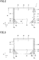
- the packaging container 1 is formed by folding a laminated sheet 2 into a W shape in side view such that the sealant layers 2C face each other. That is, as shown in Figs. 2 and 3 , the packaging container 1 is provided with a front surface portion 21 and a rear surface portion 22 in a facing arrangement so that the sealant layers 2C face each other, and a bottom surface portion 23 folded between the front surface portion 21 and the rear surface portion 22 from one end (a first end) to the other end (a second end) in the first direction of the front surface portion 21 and the rear surface portion 22.
- Each of the front surface portion 21 and the rear surface portion 22 has a height in the first direction (X direction) and a width in the second direction (Y direction) orthogonal to the first direction in the same plane.
- the X direction that is the first direction may be referred to as the height direction
- the Y direction that is the second direction may be referred to as the width direction. Therefore, the bottom surface portion 23 is provided on one of ends, that is, it is provided on a first end (one end) opposite to a second end (the other end) in the height direction (X direction) of each of the front surface portion 21 and the rear surface portion 22.
- the bottom surface portion 23 is folded in half between the front surface portion 21 and the rear surface portion 22 such that the first area 23a and the second area 23b face each other (see Fig. 4 (c) ).
- the packaging container 1 is provided with a side sealing portion 24 having two-layered structure in which edge portions of the front surface portion 21 and the rear surface portion 22 in the width direction (hereinafter may simply be referred to as edges) are overlapped with each other and are sealed, and a bottom surface sealing portion 25 having four-layered structure in which edge portions of the front surface portion 21 and the rear surface portion 22, and edge portions of the bottom surface portion 23 in the width direction (hereinafter may simply be referred to as edges) are overlapped with one another and are sealed.
- the side sealing portion 24, the bottom surface sealing portion 25, and a reinforcing sealing portion 25a to be described later are shown by hatching.
- Each of the side sealing portion 24 and the bottom surface sealing portion 25 is provided at edges of the front surface portion 21 and the rear surface portion 22, the edges facing with each other in the width direction (Y direction).
- the bottom surface sealing portion 25 extends from the first end (one side) to the second end (the other side) of the front surface portion 21 and the rear surface portion 22, and the side sealing portion 24 is connected to the bottom surface sealing portion 25 and extends from the bottom surface sealing portion 25 to the second end of the front surface portion 21 and the rear surface portion 22.
- a size 23h of the bottom folded depth where the bottom surface portion 23 is folded, in other words, the height of the bottom surface sealing portion 25 is preferably 10 to 40% of the size of the height 1h of the front surface portion 21 and the rear surface portion 22.
- the size is less than 10%, which is smaller than the above range, the bottom surface portion 23 when opened becomes narrow and the packaging container 1 cannot stably stand upright by itself.
- the size is more than 40%, which is larger than the above range, the bottom part 23 cannot be fully opened when the folded bottom surface portion 23 is attempted to be opened, and therefore the packaging container 1 cannot stably stand upright by itself.
- a more preferred range is 15 to 25%. In this range, the stability of standing upright by itself further improves.
- the packaging container 1 is provided with a reinforcing sealing portion 25a having two-layered structure in which the first area 23a, which is one of the first area 23a and the second area 23b of the bottom surface portion 23, and the front surface portion 21 are overlapped with each other and are sealed, and a reinforcing sealing portion 25b having four-layered structure in which the second area 23b, which is the other of the first area 23a and the second area 23b of the bottom surface portion 23, and the rear surface portion 22 are overlapped with each other and are sealed.
- Each of the reinforcing sealing portions 25a and 25b are provided at both edges of the front surface portion 21 and the rear surface portion 22, the edges facing each other in the width direction of the.
- the packaging container 1 is provided with a containing portion 30 surrounded by the front surface portion 21, the rear surface portion 22 and the bottom surface portion 23, and formed by sealing the front surface portion 21, the rear surface portion 22 and the bottom surface portion 23 by sealing the side sealing portion 24 and the bottom surface sealing portion 25.
- the side sealing portion 24, the bottom surface sealing portion 25 and the reinforcing sealing portions 25a and 25b are formed by thermocompression sealing, ultrasonic welding or the like.
- a point sealing portion 26 is provided toward the bottom surface sealing portion 25 and the side sealing portion 24 in order to enhance the sealing performance.
- the point sealing portion 26 is formed in a width that is 40 to 90% of the sealing width of the bottom surface sealing portion 25 and the side sealing portion 24.
- the point sealing portion 26 is provided in each of the two rims of the front surface portion 21 and the rear surface portion 22 in the width direction.
- the point sealing portion 26 preferably has a length in the bottom surface sealing portion 25 in the X direction in a ratio of 10% or more with respect to the entire length in the X direction provided toward the side sealing portion 24 and the bottom surface sealing portion 25.
- the ratio is less than 10%, the strength is insufficient, and the possibility that food or drink (content) in the containing portion 30 leaks when the packaging container 1 is dropped increases.
- the sealant layers 2C fuse with each other as shown in Fig. 5 , and therefore a sealing line is not clearly visible from the outer surface (surface on the side of the substrate 2A of the laminated sheet 2) of the packaging container 1. For this reason, the designability of the outer surface of the packaging container 1 is not impaired.
- a blanked portion 27 is provided in each of the two bottom surface sealing portions 25.
- the substrates 2A need to be bonded to each other at each bottom surface sealing portion 25 to form the bottom surface portion 23.
- the sealant layer 2C can be exposed towards the bottom surface portion 23 at the bottom surface sealing portion 25. That is, in the bottom surface sealing portion 25, the sealant layers 2C of the front surface portion 21 and that of the rear surface portion 22 can be fused together with each other through the blanked portion 27 provided in each of the first area 23a and the second area 23b of the bottom surface portion 23.
- the blanked portion 27 is preferably provided at a position that is 5 to 50% of the bottom folded depth (size 23h) from the bottom edge of the bottom surface sealing portion 25.
- the position is below this range, not only can the area of the blanked portion not be sufficiently secured, but also the impact of a drop is concentrated in a drop test, and the bag breaking resistant strength reduces.
- the position was above this range, the lower side of the bottom surface portion which is not sealed would open by the weight of the contents, and therefore it cannot stably stand upright by itself.
- An even more preferable range is 5 to 30%, and a further preferable range is 10 to 20%. In this range, both the bag breaking resistance strength in a drop test and the stability of standing upright by itself further improve.
- the blanked portion 27 is constituted by a wide slit (band-like cut off region) having a predetermined width inside a rim of the bottom surface sealing portion 25, but the blanked portion 27 may be constituted by a through-hole with a planar shape of a circle or an ellipse.
- a sealing portion 28 which seals the containing portion 30 by overlapping the front surface portion 21 and the rear surface portion 22 in double after putting food in the containing portion 30, is provided.
- a cut off part 29 is provided for releasing the upper part side of the containing portion by cutting off the upper part side of the front surface portion 21 and the rear surface portion 22 when taking out food from the containing portion 30 after retorting (after heat treatment).
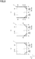
- the packaging container 1 constituted as such defines and forms, in the sheet state as shown in Figs. 4 (a) and (b) , the front surface portion 21, the bottom surface portion 23 (the first area 23a, the second area 23b) and the rear surface portion 22 in the longitudinal direction in this order.
- the bottom surface sealing portions 25, 25 are provided at both edge sides in the width direction (the second direction) of each of the first area 23a and the second area 23b.
- the side sealing portion 24 and the bottom surface sealing portion 25 are provided at both edge sides in the width direction of each of the first area 23a and the second area 23b.
- the side sealing portions 24 are provided so as to be located at both edges, and extending in the longitudinal direction (the first direction) of the packaging container in the sheet state. That is, the side sealing portion 24, the bottom surface sealing portion 25, the bottom surface sealing portion 25, the bottom surface sealing portion 25, the bottom surface sealing portion 25 and the side sealing portion 24 are provided in this order along the longitudinal direction of the packaging container 1 in the sheet state.
- the size of the bottom surface sealing portion 25 in the longitudinal direction (the first direction) is set to be approximately equal to the sizes of the first area 23a and the second area 23b along the longitudinal direction (the first direction) of the packaging container 1 in the sheet state.
- the size of the bottom surface sealing portion 25 in the longitudinal direction (the first direction) provided in the front surface portion 21 and the rear surface portion 22 preferably is approximately equal to the size of the bottom surface sealing portion 25 in the longitudinal direction (first direction) provided in the bottom surface portion 23.
- the first area 23a and the second area 23b are folded to form a peak, and the front surface portion 21 or the rear surface portion 22 and the bottom surface portion 23 are folded to form valleys, to form a W shape in side view, and the packaging container 1 in the sheet state is folded such that the front surface portion 21 and the rear surface portion 22 face each other.
- the side sealing portions 24, 24 at one edge in the width direction of the packaging container 1, and the bottom surface sealing portion 25 of the front surface portion 21 or the rear surface portion 22 and the bottom surface sealing portion 25 of the bottom surface portion 23 are placed tightly together and fixed, for example, by thermocompression sealing or ultrasonic welding. Then, by fixing the side sealing portion 24 and the bottom surface sealing portion 25 at the other edge in the width direction of the packaging container 1 in the same manner, the packaging container 1 having a shape as shown in Fig. 4 (d) is obtained.
- the packaging container 1 has a bag shape provided with the containing portion 30 where both edge parts extending in the longitudinal direction (the first direction), of the packaging container 1 in the sheet state, form an opening part.
- the packaging container 1 can be self-supported by extending the opening part, and pressing the first area 23a and the second area 23b from inside the containing portion 30 to make most of the first area 23a and the second area 23b be in contact with the surface on which the packaging container 1 is placed.
- the packaging container 1 is sealed after food is stored in the containing portion 30, by fixing the sealing portions 28 shown in Fig. 4 (a) to each other similarly to the side sealing portion 24 and the bottom surface sealing portion 25 under, for example, reduced pressure of the containing portion 30.
- the packaging container 1 When the packaging container 1 stores food therein and is stood upright with the bottom portion 23 facing downward, the food flows towards the bottom surface portion 23. Further, due to the flow of the food, the internal pressure of the bottom surface portion 23 of the containing portion 30 increases, and therefore the bottom surface portion 23 folded between the front surface portion 21 and the rear surface portion 22 opens and the one edge side (side of the bottom surface portion 23) of the containing portion 30 bulges. As a result, the packaging container 1 stands upright by itself with the bottom surface portion 23 facing downward. At this time, in order to have the packaging container 1 stably stand upright by itself, it is useful to increase the thickness of the substrate 2A to enhance the rigidity of the laminated sheet 2.
- the inventors of the present invention studied folding with a bag making machine, and found out that folding with a bag making machine is possible with a laminated sheet 2 having a Taber stiffness (stiffness) measured by a Taber stiffness tester method in accordance with JIS (Japanese Industrial Standards) P8125: 2000 of 1.01 mN ⁇ m or less. Therefore, since folding with a bag making machine is possible with a laminated sheet 2 having a stiffness of approximately 1.01 mN ⁇ m or less, it is possible to provide the stably freestanding packaging container 1.
- the term “rigidity” refers to paper stiffness, which is generally called “koshi” in Japanese. Further, the Taber stiffness tester method is a type of a load test method.
- the laminated sheet 2 includes a paper substrate as the substrate 2A.
- the paper substrate can significantly reduce the energy required during combustion as compared to a plastic substrate during disposal. Therefore, the packaging container 1 constituted by the laminated sheet 2 including a paper substrate can reduce load on the environment.
- the bottom surface portion 23 of the packaging container 1 is folded between the front surface portion 21 and the rear surface portion 22 from the front surface portion 21 and the rear surface portion 22, and therefore a sealing portion where the front surface portion 21 and the rear surface portion 22, and the bottom surface portion 23 are overlapped with one another and are sealed is not present at the first end of the front surface portion 21 and the rear surface portion 22. If a sealing portion were present in the first end of the front surface portion 21 and the rear surface portion 22, and also the packaging container stands upright with the bottom portion 23 facing downward, the bottom surface portion would be in a state of being raised from the installation surface where the bottom surface portion 23 of the packaging container 1 contacts, for example, the turntable of a microwave oven.
- a part of the bottom surface portion 23 would be in a state of being separated (floating) from the turntable.
- the heating power on the installation surface side is high, and therefore heating of food is affected in a packaging container where the bottom surface portion is raised from the installation surface.
- a sealing portion is not present at the first end of the front surface portion 21 and the rear surface portion 22, and therefore the bottom surface portion 23 would not be in a state of being raised from the installation surface. Accordingly, heating with a microwave oven can be performed efficiently as compared to the case where a sealing portion is present at the first end of the front surface portion 21 and the rear surface portion 22.
- the packaging container 1 may use a sheet containing cellulose as a substrate. Further, the packaging container 1 may use, as paper substitute, a stone paper mainly composed of an inorganic mineral, for example, a new material LIMEX mainly composed of limestone developed and manufactured by TBM Co., Ltd. may be used.
- a stone paper mainly composed of an inorganic mineral for example, a new material LIMEX mainly composed of limestone developed and manufactured by TBM Co., Ltd. may be used.
- Stone paper is a material that uses limestone and resin.
- the inorganic mineral refers to a natural mineral such as a limestone, but may also include an artificial material having similar or the same properties as a natural mineral. Examples of the artificial material include synthetic calcium carbonate or synthetic mica.
- materials including cellulose include paper, those using paper and resin, for example, those having resin coated on paper, and those having cellulose fibers coated on resin.
- Cellulose itself is not limited to plant-derived substances such as wood and grass, but includes cellulose-like substances derived from natural polysaccharides (substances constituting silk, substances produced by sea squirts), substances where substituent(s) is(are) introduced to cellulose or cellulose-like substances, or substances where their molecular weights are made smaller (lengths of the molecules are shortened) and the like.
- thermoplastic resins polyethylene, polypropylene, PET, polyvinyl acetate resin, acrylic resin and the like
- heat (photo) curable resins urethane, epoxy, phenol resin and the like
- water-soluble polymers polyvinyl alcohol, thermoplastic resins, thermosetting resins which can be applied as water-soluble dispersions
- the packaging container 1 of the first embodiment uses a paper substrate as the substrate 2A of the laminated sheet 2. In this case, heating with a microwave oven is possible.
- a packaging container using a laminated sheet having an aluminum foil held between various plastic films is known, but this packaging container cannot be heated with a microwave oven.
- a packaging container using alumina or silica vapor deposited film which can be heated with a microwave oven is known, but the alumina or silica vapor deposited film is thin, and therefore the stiffness is low and the stability of packaging container to stand upright by itself in particular on the palm is low.
- the packaging container 1 of the first embodiment has high stiffness, and it is possible to eat and drink directly from the storage container during an emergency or disaster.
- the packaging container 1 of the first embodiment uses a paper substrate as the substrate 2A of the laminated sheet 2, and therefore even when processed with heat, a design and the like drawn on the front surface portion 21 and the rear surface portion 22 are not affected.
- it is environmentally friendly and excessive packaging is not necessary.
- it is lightweight, and is also useful as an alternative to cans and bottles from the perspective of transportation cost and ease of disposal in terms of environment.
- the laminated sheet 2 shown in Fig. 7 (a) is prepared.
- the laminated sheet 2 has a laminated structure where at least the substrate 2A, the barrier layer 2B and the sealant layer 2C are laminated in this order.
- the laminated sheet 2 is formed in a rectangle having an X direction (a height direction) which is a first direction and a Y direction (a width direction) which is a second direction, the X direction and the Y direction being perpendicular to each other in the same plane.
- the laminated sheet 2 has a structure where the front surface portion 21, the first area 23a and the second area 23b of the bottom surface portion 23, and the rear surface portion 22 are defined by scores in this order along the X direction.
- the laminated sheet 2 is folded in half such that the front surface portion 21 and the rear surface portion 22, and the first area 23a and the second area 23b of the bottom surface portion 23 are respectively overlapped with each other.
- the laminated sheet 2 is folded along a score between the first area 23a and the second area 23b of the bottom surface portion 23 such that the sealant layer 2C on a first side faces the sealant layer 2C on a second side. That is, in the laminated sheet 2 folded in half, the sealant layer 2C of the front surface portion 21 and that of the rear surface portion 22 face each other (see Fig.
- the sealant layer 2C of the first area 23a and that of the second area 23b of the bottom surface portion 23 face each other.
- the substrate 2A of each of the front surface portion 21 and the rear surface portion 22 serves as an outermost layer (see Fig. 5 ), and similarly the substrate 2A of each of the first area 23a and the second area 23b of the bottom surface portion 23 serves as an outermost layer.
- the blanked portion 27 is formed where a part of each of the first area 23a and the second area 23b is removed from each of the rims on both sides of the first area 23a and the second area 23b in the Y direction.
- the blanked portion 27 is formed by performing a blanking process (punching process) in a state where, for example, the first area 23a and the second area 23b are aligned with each other.
- each of the substrates 2A of the first area 23a and the second area 23b of the bottom surface portion 23 face each other.
- each of the sealant layers 2C of the front surface portion 21 and the first area 23a face each other, and each of the sealant layers 2C of the rear surface portion 22 and the second area 23b face each other.
- each of the sealant layers 2C of the front surface portion 21 and the first area 23a, and each of the sealant layers 2C of the rear surface portion 22 and that of the second area 23b are respectively sealed with the first area 23a and the second area 23b of the bottom surface portion 23 being overlapped with each other.
- These sealings are performed by, for example, thermocompression sealing or ultrasonic welding.
- the reinforcing sealing portion 25a is formed where the sealant layer 2C of the front surface portion 21 and that of the first area 23a are sealed to each other, and the reinforcing sealing portion 25b is formed where the sealant layer 2C of the rear surface portion 22 and that of the second area 23b are sealed to each other.
- the reinforcing sealing portion 25a is formed in an oblique direction towards the bottom edge 21a of the front surface portion 21 (a folded portion between the front surface portion 21 and the first area 23a of the bottom surface portion 23 as shown in Fig. 7 (d) ) from each of the edges extending in the X direction of the front surface portion 21.
- the reinforcing sealing portion 25b is also formed in an oblique direction towards the bottom edge 22a of the rear surface portion 22 (a folded portion between the rear surface portion 22 and the second area 23b of the bottom surface portion 23 as shown in Fig. 7 (d) ) from each of the edges extending in the X direction of the rear surface portion 22.
- the sealant layers 2C are sealed to one another throughout the double-layered region where the front surface portion 21 and the rear surface portion 22 are overlapped with each other, and the quadruple-layered region where the front surface portion 21, the rear surface portion 22, the first area 23a and the second area 23b of the bottom surface portion 23 are overlapped with one another.
- These sealings are performed by, for example, thermocompression sealing or ultrasonic welding.
- the point sealing portions 26 are formed where the sealant layers 2C are sealed to one another throughout the double-layered region and the quadruple-layered region.
- the sealant layer 2C of the front surface portion 21 and that of the rear surface portion 22 is sealed to each other.
- These sealings are performed by, for example, thermocompression sealing or ultrasonic welding.
- the side sealing portion 24 and the bottom surface sealing portion 25 are formed, the side sealing portion 24 having two-layered structure in which the sealant layers 2C are sealed to each other by overlapping the edges of the front surface portion 21 and of the rear surface portion 22 in the Y direction, and the bottom surface sealing portion 25 having four-layered structure in which the sealant layers 2C are sealed to one another by overlapping the edges of the front surface portion 21, of the rear surface portion 22, of the first area 23 and of the second area 23b of the bottom surface portion 23 in the Y direction.
- the laminated sheet 2 where the side sealing portion 24, the bottom surface sealing portion 25, the reinforcing sealing portions 25a and 25b, and point sealing portions are formed, is cut into a predetermined shape, thereby producing the packaging container 1 shown in Figs. 2 and 3 which is almost completed.
- the notch 29 is formed in the side sealing portion 24.
- the packaging container 1 According to the method of producing the packaging container 1 according to the first embodiment of the present invention, it is possible to produce the stably freestanding packaging container.
- the sealant layers 2C of the laminated sheet 2 in the side sealing portion 24, the bottom surface sealing portion 25, the reinforcing sealing portions 25a and 25b, and the point sealing portions 26 can be sealed to one another, and therefore the packaging container 1 excellent in sealing performance can be produced.
- the reinforcing sealing step (see Fig. 8 (a) ) forming the reinforcing sealing portions 25a and 25b, the point sealing step (see Fig. 8 (b) ) forming the point sealing portions 26, and the side face and bottom face sealing step (see Fig. 8 (c) ) forming the side sealing portion 24 and the bottom surface sealing portion 25 have been described in this order, but the order of these sealing steps is not limited to this and there is no particular order.
- the reinforcing sealing step shown in Fig. 8 (a) is described as S1
- the point sealing step shown in Fig. 8 (b) is described as S2
- an insertion part that makes it possible to insert a straw into the containing portion 30 from the outside, or a vapor discharge part that allows vapor in the containing portion 30 to escape outside when pressure in the containing portion 30 rises to a certain level or higher by heating the content (food or drink) in the sealed containing portion 30 may be provided.
- Example 1 the same packaging container as that of the first embodiment was provided using a laminated sheet made of the following materials as the laminated sheet 2.
- the substrate 2A a paper substrate having a basis weight of 70 g/m 2 and a thickness of 133 ⁇ m was used. Further, for the barrier layer 2B, a barrier film having a thickness of 12 ⁇ m by deposition of an inorganic compound was used. Further, for the sealant layer 2C, an unstretched polypropylene film (CPP film) having a thickness of 70 ⁇ m was used. Further, the size 23h of the bottom folded depth was set to 18% of the height 1h of the packaging container 1.
- CPP film unstretched polypropylene film
- the packaging container of the Example 1 stably stood upright by itself with food being contained therein.
- Example 2 the packaging container was provided using a laminated sheet made of the following materials as the laminated sheet 2.
- the substrate 2A a paper substrate having a basis weight of 80 g/m 2 and a thickness of 139 ⁇ m was used. Further, for the barrier layer 2B and the sealant layer 2C, the same films as those of Example 1 were used. Further, the size 23h of the bottom folded depth was set to the same size as that of the Example 1.
- the packaging container of the Example 2 also stably stood upright by itself with food being contained therein.
- Example 3 the packaging container was provided using a laminated sheet made of the following materials as the laminated sheet 2.
- the substrate 2A a paper substrate having a basis weight of 90 g/m 2 and a thickness of 146 ⁇ m was used. Further, for the barrier layer 2B and the sealant layer 2C, the same films as those of Example 1 were used. The size 23h of the bottom folded depth was set to the same size as that of the Example 1.
- the packaging container of the Example 3 also stably stood up by itself with food being contained therein.
- Example 4 the packaging container was provided using a laminated sheet made of the following materials as the laminated sheet 2.
- the substrate 2A a paper substrate having a basis weight of 100 g/m 2 and a thickness of 157 ⁇ m was used. Further, for the barrier layer 2B and the sealant layer 2C, the same films as those of Example 1 were used. Further, the size 23h of the bottom folded depth was set to the same size as that of the Example 1.
- the packaging container of the Example 4 also stably stood upright by itself with food being contained therein.
- Example 5 the packaging container was provided using a laminated sheet made of the following materials as the laminated sheet 2.
- the substrate 2A a paper substrate having a basis weight of 110 g/m 2 and a thickness of 177 ⁇ m was used. Further, for the barrier layer 2B and the sealant layer 2C, the same films as those of Example 1 were used. Further, the size 23h of the bottom folded depth was set to the same size as that of the Example 1.
- the packaging container of the Example 5 also stably stood upright by itself with food being contained therein.
- Example 6 the packaging container was produced using a laminated sheet made of the following materials as the laminated sheet 2.
- the substrate 2A a paper substrate having a basis weight of 120 g/m 2 and a thickness of 193 ⁇ m was used. Further, for the barrier layer 2B and the sealant layer 2C, the same films as those of Example 1 were used. Further, the size 23h of the bottom folded depth was set to the same size as that of the Example 1.
- the packaging container of the Example 6 also stably stood upright by itself with food being contained therein.
- Example 7 the packaging container was provided using a laminated sheet made of the following materials as the laminated sheet 2.
- the substrate 2A a paper substrate having a basis weight of 140 g/m 2 and a thickness of 221 ⁇ m was used. Further, for the barrier layer 2B and the sealant layer 2C, the same films as those of Example 1 were used. Further, the size 23h of the bottom folded depth was set to the same size as that of the Example 1.
- the packaging container of the Example 7 also stably stood upright by itself with food being contained therein.
- Example 8 the packaging container was provided using a laminated sheet made of the following materials as the laminated sheet 2.
- the substrate 2A a paper substrate having a basis weight of 80 g/m 2 and a thickness of 139 ⁇ m was used. Further, for the barrier layer 2B, an identical film to that of Example 1 was used. Further, for the sealant layer 2C, an unstretched polypropylene film (CPP film) having a thickness of 30 ⁇ m was used. Further, the size 23h of the bottom folded depth was set to the same size as that of the Example 1.
- CPP film unstretched polypropylene film
- the packaging container of the Example 8 also stably stood upright by itself with food being contained therein.
- Example 9 the packaging container was provided using a laminated sheet made of the following materials as the laminated sheet 2.
- the substrate 2A an identical paper substrate to that of Example 8 was used. Further, for the barrier layer 2B, an identical film to that of Example 1 was used. Further, for the sealant layer 2C, an unstretched polypropylene film (CPP film) having a thickness of 40 ⁇ m was used. Further, the size 23h of the bottom folded depth was set to the same size as that of the Example 1.
- CPP film unstretched polypropylene film
- the packaging container of the Example 9 also stably stood upright by itself with food being contained therein.
- Example 10 the packaging container was provided using a laminated sheet made of the following materials as the laminated sheet 2.
- the same paper substrate as that of Example 8 was used. Further, for the barrier layer 2B, an identical film to that of Example 1 was used. Further, for the sealant layer 2C, an unstretched polypropylene film (CPP film) having a thickness of 50 ⁇ m was used. Further, the size 23h of the bottom folded depth was set to the same size as that of the Example 1.
- CPP film unstretched polypropylene film
- the packaging container of the Example 10 also stably stood upright by itself with food being contained therein.
- Example 11 the packaging container was provided using a laminated sheet made of the following materials as the laminated sheet 2.
- the same paper substrate as that of Example 8 was used. Further, for the barrier layer 2B, an identical film to that of Example 1 was used. Further, for the sealant layer 2C, an unstretched polypropylene film (CPP film) having a thickness of 60 ⁇ m was used. Further, the size 23h of the bottom folded depth was set to the same size as that of the Example 1.
- CPP film unstretched polypropylene film
- the packaging container of the Example 11 also stably stood upright by itself with food being contained therein.
- the packaging container was provided using a laminated sheet made of the following materials as a laminated sheet.
- the substrate 2A a plastic film substrate having a density of 1. 35 g/cm 3 (converted to a basis weight of 20 g/m 2 ) and a thickness of 15 ⁇ m was used. Further, for the barrier layer 2B, an identical film to that of Example 1 was used. Further, for the sealant layer 2C, an unstretched polypropylene film (CPP film) having a thickness of 70 ⁇ m was used. Further, the size of the bottom folded depth was set to the same size as that of the Example 1.
- CPP film unstretched polypropylene film
- Taber stiffness (stiffness) of the laminated sheet 2 was measured by a Taber stiffness tester method in accordance with JIS-P8125: 2000. Further, when stiffness was smaller than 0.95 mN ⁇ m, it was determined that folding with a bag making machine was possible and was evaluated as "VERY GOOD", and even when stiffness was 0.95 mN ⁇ m or more and 1.01 mN ⁇ m or less, it was determined that folding with a bag making machine was possible and was evaluated as "GOOD”.
- Example 1 The measured value of Example 1 was 0.27 mN ⁇ m, that of Example 2 was 0.34 mN ⁇ m, that of Example 3 was 0.44 mN ⁇ m, that of Example 4 is 0.63 mN ⁇ m, that of Example 5 was 0.66 mN ⁇ m, that of Example 6 was 0.84 mN ⁇ m, that of Example 7 was 1.01 mN ⁇ m, those of Examples 8 to 11 were all 1.01 mN ⁇ m or less, and stiffness was too low to make any measurement in Comparative Example 1.
- the evaluation results are shown in Table 1.
- sealing strength was measured at side sealing portions (the side sealing portion 24 and the bottom surface sealing portion 25) of the packaging container by a test method of a heat sealing soft packaging bag and a semi-stiff container in accordance with JIS-Z0238: 1998. Further, when the sealing strength was 40 N/15 mm or more, it was determined as suitable and was evaluated as "VERY GOOD", and even when the sealing strength was larger than 23 [N/15 mm] and less than 40 [N/15 mm], it was determined as suitable and was evaluated as "GOOD”. The evaluation results are shown in Table 1. In the Japan Food Sanitation Law, it is set forth that the sealing strength after retort (after heat processing) should be more than 23 [N/15 mm].
- Example 1 was 61.1 [N/15 mm], that of Example 2 was 54.2 [N/15 mm], that of Example 3 was 49.5 [N/15 mm], that of Example 4 was 47.1 [N/15 mm], that of Example 5 was 48.8 [N/15 mm], that of Example 6 was 45.7 [N/15 mm], that of Example 7 was 25.8 [N/15 mm], that of Example 8 was 30.1 [N/15 mm], that of Example 9 was 25.4 [N/15 mm] and those of Examples 10 and 11 and Comparative Example 1 were all more than 23 [N/15 mm].
- Examples 1 to 11 and Comparative Example 1 drop tests of the packaging containers were carried out for 36 bags by a transportation drop test (free drop test among impact tests) in accordance with JIS-Z0200: 2013, and when the number of leaked bags was zero, it was evaluated as "VERY GOOD", and when the number of leaked bags was 1 to 7, it was evaluated as "GOOD”.
- the test was performed by dropping the packaging containers from a height of 60 cm.
- the evaluation results are shown in Table 1.
- the number of leaks in Examples 1 to 7 was 4 or less
- that in Example 8 was 7, that in Example 9 was 6, that in Example 10 was 5, that in Example 11 was 4, and that in Comparative Example 1 was 7 or less.
- the sealant layer 2C comprising a paper substrate having a basis weight of 60 to 140 g/m 2 and a thickness of 120 to 220 ⁇ m as the substrate 2A, the barrier layer 2B and a CPP film having a thickness of 70 ⁇ m or more as the sealant layer 2C laminated in this order for the laminated sheet 2.
- the packaging container 1 having the size 23h of the bottom folded depth to be 15% to 25% of the size 1h of the height of the packaging container 1 could stand up by itself.
- Example 2-1A [Example 2-1A, Example 2-1B]
- Example 2-1A and Example 2-1B the bottom surface sealing portion 25 of the packaging container of Example 2 was provided with the blanked portion 27 at a position of 5 mm (12.5%) from the bottom edge thereof. Height of the bottom surface sealing portion 25 in the X direction
- Example 2-2A [Example 2-2A, Example 2-2B]
- Example 2-2A and Example 2-2B the bottom surface sealing portion 25 of the packaging container of Example 2 was provided with the blanked portion 27 at a position of 20 mm (50%) from the bottom edge thereof.
- Example 2-3A [Example 2-3A, Example 2-3B]
- Example 2-3A and Example 2-3B the bottom surface sealing portion 25 of the packaging container of Example 2 is not provided with the blanked portion 27.
- Examples 2-1A to 2-3B five packaging containers 1 containing 300 ml of water and sealed, and five packaging containers 1 containing 200 ml of water and sealed were prepared.
- the packaging containers 1 containing 300 ml of water were dropped from a height of 50 cm, and the packaging containers 1 containing 200 ml of water from a height of 100 cm for 10 times for each packaging container 1, and the state of broken bags at the intersection point parts (parts where the bottom surface sealing portion 25 and the reinforcing sealing portions 25a, 25b intersect), the reinforcing sealing portions 25a, 25b and the bottom surface portion 23 were evaluated.
- Table 2 each of the intersection point, the V seal, and the bottom is shown.
- Examples 2-1A, 2-2A and 2-3A are before retort, and Examples 2-1B, 2-2B and 2-3B are after retort.
- the evaluation results are shown in Table 2.
- Table 2 shows the number of broken bags of the five bags.
- Construction Evaluation Substrate Thickness of barrier layer ( ⁇ m) Thickness of sealant layer ( ⁇ m) Position of blanked portion 300 ml of water 200 ml of water Basis weight (g/m 2 ) Thickness ( ⁇ m) Height 50 cm Height 100 cm (mm) (%) Intersection point V seal Base Intersection point V seal Base Intersection point V seal Base
- Example 2-1A 80 139 12 70 5 12.5 0 1 0 0 0 0 0 0 0
- Example 2-1B 80 139 12 70 5 12.5 0 0 0 0 0 0 0
- Example 2-2A 80 139 12 70 20 50 1 0 0 0 0 1
- Example 2-2B 80 139 12 70 20 50 0
- Examples 2-1A to 2-3B it was also confirmed from Examples 2-1A to 2-3B that it is preferable to provide the blanked portion 27 at a position of 2 to 12 mm above the bottom edge 25c of the bottom surface sealing portion 25.
- the position of the blanked portion 27 of 2 to 12 mm above the bottom edge 25c is equivalent to the size 23h of the bottom folded depth being 5 to 30% of the length of the bottom surface sealing portion 25 in the X-direction.
- the position of the blanked portion in Table 2 is the case where the size 23h of the bottom folded depth is 40 mm, and 5 mm of the position of the blanked portion is equivalent to 12.5% of the size 23h of the bottom folded depth.
- 20 mm of the position of the blanked portion is equivalent to 50% of the size 23h of the bottom folded depth.
- Example 2-4 at the boundary part between the side sealing portion 24 and the bottom surface sealing portion 25 of the packaging container of the Example 2, the point sealing portion 26 with a width of 90% of the sealing width of the side sealing portion 24 and the bottom surface sealing portion 25 was provided toward each of the side sealing portion 24 and the bottom surface sealing portion 25.
- Example 2-5 at the boundary part between the side sealing portion 24 and the bottom surface sealing portion 25 of the packaging container of the Example 2, the point sealing portion 26 with a width of 60% of the sealing width of the side sealing portion 24 and the bottom surface sealing portion 25 was provided toward each of the side sealing portion 24 and the bottom surface sealing portion 25.
- Example 2-6 at the boundary part between the side sealing portion 24 and the bottom surface sealing portion 25 of the packaging container of the Example 2, the point sealing portion 26 with a width of 40% of the sealing width of the side sealing portion 24 and the bottom surface sealing portion 25 was provided toward each of the side sealing portion 24 and the bottom surface sealing portion 25.
- Examples 2-4 to 2-6 similarly to the Examples 1 to 11 and Comparative Example 1 mentioned above, by transportation drop tests (free drop tests among impact tests) in accordance with the packaged cargo of JIS-Z0200: 2013, drop tests of packaging containers each containing 200 ml of water were performed for 42 bags, drop tests of packaging containers each containing 250 ml of water were performed for 36 bags, and drop tests of packaging containers each containing 300 ml of water were performed for 30 bags, and the numbers of leaks were evaluated.
- the test was performed by dropping the packaging containers from a height of 60 cm.
- the evaluation results are shown in Table 3.
- Example 2-5 As can be seen from Table 3, it was confirmed in Example 2-5 that liquid leaks did not occur in the case where the volume of water was 200 ml, and in the case where the volume of water was 250 ml. Thereby, regarding the value of the sealing width of the point sealing portion 26 with respect to the sealing widths of the bottom surface sealing portion 25 and the side sealing portion 24, it is found that the center of the value that shows improvement is approximately 60%, and the range of the value showing a trend of improvement is 40 to 90%.
- a packaging container 1A according to the second embodiment of the present invention has nearly the same constitution as the packaging container 1 of the first embodiment mentioned above, and the following constitution is different.
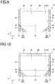
- the packaging container 1A of the second embodiment is provided with a cutout area 31A in the sealing portion 28 of each of the front surface portion 21 and the rear surface portion 22.
- the cutout area 31 is surrounded by, for example, a perforation line, and after putting food in the containing portion 30 and sealing the sealing portion 28, it can be easily cut out from the sealing portion 28.
- the cutout area 31A has a length in the width direction (Y direction) longer than the length in the height direction (X direction) so that a cutout hole 32A after the cutout area 31A is cut out can be used, for example, as a handle.
- the cutout hole 32A after the cutout area 31A is cut out can be used as a handle, and concurrently, by holding the cutout hole 32A as a handle, it is possible to easily transport the heated packaging container 1A heated with a microwave oven or the like.
- the shape of the cutout area 31A it is possible to use the cutout area 31A after being cut out from the sealing portion 28 as a tool such as a spoon so that the sealing portion 28 can be effectively used.
- the cutout area 31A is provided in the sealing portion 28, it is preferable to enhance the sealing strength by making the width in the X direction larger than the sealing portion 28 of the first embodiment mentioned above.
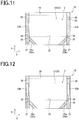
- a packaging container 1B according to the third embodiment of the present invention modifies the position of forming a cutout area. That is, as shown in Fig. 11 , the packaging container 1B of the third embodiment is provided with a cutout area 31B in each of two side sealing portions 24 positioned on the opposite sides in the width direction (Y direction). In the third embodiment also, the cutout area 31B is surrounded by, for example, a perforation line, and after putting food in the containing portion 30 and sealing the sealing portion 28, it can be easily cut out from the side sealing portion 24. Moreover, as shown in Fig.
- the cutout area 31B has a length in the width direction (Y direction) longer than the length in the height direction (X direction) so that a cutout hole 32B after the cutout area 31B is cut out can be used, for example, as a handle.
- the cutout hole 32B after the cutout area 31B is cut out can be used as a handle, and concurrently, by using the cutout hole 32B as a handle, it is possible to easily transport the heated packaging container 1B heated with a microwave oven or the like.
- the shape of the cutout area 31B it is possible to use the cutout area 31B after being cut out from the sealing portion 28 as a tool such as a spoon so that the side sealing portion 24 can be effectively used.
- the cutout area 31B is provided in the side sealing portion 24, it is preferable to increase the width in the Y direction as compared to the first and second embodiments mentioned above to enhance the sealing strength.
- the cutout area 31B is provided in each of the two side sealing portions 24 was described, but the cutout area 31B may be provided in either one of the two side sealing portions 24.
- packaging containers 1, 1A and 1B for ready-made meals were described.
- the present invention is not limited to this embodiment, and can be applied to packaging containers for drinks, food and the like.
Landscapes
- Engineering & Computer Science (AREA)
- Mechanical Engineering (AREA)
- Food Science & Technology (AREA)
- Life Sciences & Earth Sciences (AREA)
- Bag Frames (AREA)
- Packages (AREA)
- Cartons (AREA)
- Wrappers (AREA)
Abstract
Description
- The present invention relates to a packaging container and a method of producing the same, and in particular, to a packaging container for food and beverages such as retort food and drinks and a technique that may be effectively applied in producing the same.
- Conventional packaging containers for ready-made meals such as baby food and nursing care food, and boiled food such as curry and fish include cans, bottles and retort pouches constituted by laminated sheets in which aluminum foil is held between various plastic films. In recent years, retort pouches including an alumina or silica vapor deposited film as a substrate of laminated sheet, which can be used for cooking with a microwave oven, have also been widely distributed (see PTL 1). Use of a retort pouch such as the packaging bag of PTL1 as an alternative to cans and bottles is advantageous in view of transportation cost and ease of disposal in terms of environment.
- [PTL 1] Patent No.
4232246 - Due to the recent growing awareness of disaster management, it has become an important feature to be able to eat and drink directly from a storage container providing a stock of food at the time of a disaster.
- However, according to study by the inventors of the present invention, when a plastic film is used as a substrate as in
PTL 1, the film may be low in stiffness, and in particular, there is room for improvement in applying the film to a stably freestanding packaging container. Although it is possible to enhance the stiffness by increasing the thickness of the plastic film of the substrate, it becomes difficult to dispose of, and further, the load on the environment becomes larger. - The present invention has been made in view of the circumstances mentioned above, and the object thereof is to provide a stably freestanding packaging container and a method of producing the same.
- In order to achieve the object mentioned above, a packaging container according to one aspect of the present invention includes a laminated sheet where at least a substrate, a barrier layer and a sealant layer are laminated together in this order, the laminated sheet having a rigidity (stiffness) of 1.01 mN·m or less measured by a Taber stiffness tester method in accordance with JIS-P8125.
- Moreover, the method of producing a packaging container according to one aspect of the present invention includes:
- a step of preparing a laminated sheet including a substrate, a barrier layer and a sealant layer laminated together in this order, wherein the laminated sheet is formed in a rectangle having a first direction and a second direction perpendicular to each other, and a front surface portion, a first area and a second area of a bottom surface portion, and a rear surface portion are defined and formed in this order along the first direction;
- a step of folding the laminated sheet in half so that the folded sealant layers face each other, and the front surface portion and the rear surface portion, and the first area and the second area of the bottom surface portion are respectively overlapped with each other;
- a step of forming a blanked portion at both edges of the first area and the second area in the second direction of the first area and the second area by removing part of the both edges of the first area and the second area with the first area and the second area of the bottom surface portion being overlapped with each other;
- a step of folding the first area and the second area inside between the front surface portion and the rear surface portion such that the blanked portions of the first area and the second area face each other, and the first area and the second area are overlapped with each other; and
- a step of sealing each sealant layer of the front surface portion and the rear surface portion, each sealant layer of the front surface portion and the first area of the bottom surface portion, each sealant layer of the front surface portion and the second area of the bottom surface portion, and each sealant layer of the front surface portion and the rear surface portion through each of the blanked portions of the first area and the second area at both end portions of the front surface portion and the rear surface portion in the second direction.
- According to one aspect of the present invention, it is possible to provide a stably freestanding packaging container and a method of producing the same.
-
-
Fig. 1 is a cross-sectional view illustrating a cross-sectional structure of a laminated sheet used in the packaging container according to a first embodiment of the present invention. -
Fig. 2 is a front view of a front face side of the packaging container according to the first embodiment of the present invention. -
Fig. 3 is a rear view of a rear face side opposite to the front face of the packaging container according to the first embodiment of the present invention. -
Fig. 4 is a set of perspective views illustrating an assembly method of the packaging container according to the first embodiment of the present invention. -
Fig. 5 is a cross-sectional view illustrating a cross-sectional structure taken along the line II-II inFig. 2 . -
Fig. 6 is a cross-sectional view illustrating a cross-sectional structure taken along the line III-III inFig. 2 . -
Fig. 7 is a set of diagrams illustrating a method of producing the packaging container according to the first embodiment of the present invention. -
Fig. 8 is a set of diagrams illustrating a method of producing the packaging container according to the first embodiment of the present invention. -
Fig. 9 is a front view of a front face side of the packaging container according to a second embodiment of the present invention. -
Fig. 10 is a front view illustrating a state where a cutout area shown inFig. 9 is cut out. -
Fig. 11 is a front view of a front face side of the packaging container according to a third embodiment of the present invention. -
Fig. 12 is a front view showing a state where a cutout area shown inFig. 11 is cut out. - A packaging container according to embodiments of the present invention is hereinafter described with reference to the drawings. Here, the drawings are schematic, and the relationship between the thickness and planar dimensions, the ratios of the thicknesses of each layer, and the like, are different from actual ones. The following embodiments exemplify configurations embodying the technical concept of the invention. The technical concept of the invention should not be construed as limiting materials, shapes and structures of constituent parts to those set out hereinafter. The technical idea of the present invention can be modified in various ways within the technical scope defined by the claims.
- In the following embodiments, as an example, a packaging container for a ready-made meal application that can be stored for a long time shall be described.
- As shown in
Figs. 1 to 4 , apackaging container 1 according to the first embodiment of the present invention is constituted mainly by a laminatedsheet 2. - As shown in
Fig. 1 , the laminatedsheet 2 has a laminated structure including asubstrate 2A that enhances the rigidity (stiffness) of the laminated sheet, abarrier layer 2B excellent in various barrier properties to oxygen, ultraviolet rays and the like, and asealant layer 2C excellent in sealing properties including thermocompression sealing properties, laminated in this order. In this embodiment, as thesubstrate 2A, for example, a paper base having a basis weight of 60 to 140 g/m2 and a thickness of 120 to 220 µm is used. Moreover, as thebarrier layer 2B, for example, a barrier film having a thickness of the order of 12 µm, which is formed by vapor depositing an inorganic compound, is used. Moreover, as thesealant layer 2C, for example, an unstretched polypropylene film (CPP film) having a thickness of 70 µm or more is used. - For example, the oxygen permeability of the laminated sheet 2 (oxygen transmission rate) was measured with an apparatus of model number: OXTRAN 2/21 ML manufactured by MOCON Co. for a plurality of laminated
sheets 2 at 30°C and at 70% RH (relative humidity), and values of 0.01, 0.002, 0.039 and 0.014 cc/m2/day/atm were obtained. This measurement method was in accordance with the MOCON method (JIS-K7126-2: 2006). - Moreover, water vapor permeability of a plurality of laminated
sheets 2 was measured by a cup method at 40°C and at 90% RH (relative humidity), and values of 0.565, 0.651, 0.929 and 0.957 g/m2 /day were obtained. This measurement method was in accordance with JIS-Z0208: 1976. - The
packaging container 1 is formed by folding a laminatedsheet 2 into a W shape in side view such that thesealant layers 2C face each other. That is, as shown inFigs. 2 and 3 , thepackaging container 1 is provided with afront surface portion 21 and arear surface portion 22 in a facing arrangement so that thesealant layers 2C face each other, and abottom surface portion 23 folded between thefront surface portion 21 and therear surface portion 22 from one end (a first end) to the other end (a second end) in the first direction of thefront surface portion 21 and therear surface portion 22. Each of thefront surface portion 21 and therear surface portion 22 has a height in the first direction (X direction) and a width in the second direction (Y direction) orthogonal to the first direction in the same plane. In this embodiment, the X direction that is the first direction may be referred to as the height direction, and the Y direction that is the second direction may be referred to as the width direction. Therefore, thebottom surface portion 23 is provided on one of ends, that is, it is provided on a first end (one end) opposite to a second end (the other end) in the height direction (X direction) of each of thefront surface portion 21 and therear surface portion 22. Thebottom surface portion 23 is folded in half between thefront surface portion 21 and therear surface portion 22 such that thefirst area 23a and thesecond area 23b face each other (seeFig. 4 (c) ). - Moreover, the
packaging container 1 is provided with aside sealing portion 24 having two-layered structure in which edge portions of thefront surface portion 21 and therear surface portion 22 in the width direction (hereinafter may simply be referred to as edges) are overlapped with each other and are sealed, and a bottomsurface sealing portion 25 having four-layered structure in which edge portions of thefront surface portion 21 and therear surface portion 22, and edge portions of thebottom surface portion 23 in the width direction (hereinafter may simply be referred to as edges) are overlapped with one another and are sealed. Further, inFigs. 2 and 3 , theside sealing portion 24, the bottomsurface sealing portion 25, and a reinforcingsealing portion 25a to be described later are shown by hatching. Each of theside sealing portion 24 and the bottomsurface sealing portion 25 is provided at edges of thefront surface portion 21 and therear surface portion 22, the edges facing with each other in the width direction (Y direction). The bottomsurface sealing portion 25 extends from the first end (one side) to the second end (the other side) of thefront surface portion 21 and therear surface portion 22, and theside sealing portion 24 is connected to the bottomsurface sealing portion 25 and extends from the bottomsurface sealing portion 25 to the second end of thefront surface portion 21 and therear surface portion 22. Asize 23h of the bottom folded depth where thebottom surface portion 23 is folded, in other words, the height of the bottomsurface sealing portion 25 is preferably 10 to 40% of the size of theheight 1h of thefront surface portion 21 and therear surface portion 22. When the size is less than 10%, which is smaller than the above range, thebottom surface portion 23 when opened becomes narrow and thepackaging container 1 cannot stably stand upright by itself. Moreover, when the size is more than 40%, which is larger than the above range, thebottom part 23 cannot be fully opened when the foldedbottom surface portion 23 is attempted to be opened, and therefore thepackaging container 1 cannot stably stand upright by itself. A more preferred range is 15 to 25%. In this range, the stability of standing upright by itself further improves. - Moreover, the
packaging container 1 is provided with a reinforcingsealing portion 25a having two-layered structure in which thefirst area 23a, which is one of thefirst area 23a and thesecond area 23b of thebottom surface portion 23, and thefront surface portion 21 are overlapped with each other and are sealed, and a reinforcingsealing portion 25b having four-layered structure in which thesecond area 23b, which is the other of thefirst area 23a and thesecond area 23b of thebottom surface portion 23, and therear surface portion 22 are overlapped with each other and are sealed. Each of the reinforcingsealing portions front surface portion 21 and therear surface portion 22, the edges facing each other in the width direction of the. The reinforcingsealing portions front surface portion 21 and therear surface portion 22, extend from the first end of thefront surface portion 21 and therear surface portion 22 toward one bottomsurface sealing portion 25, and is connected to the one bottomsurface sealing portion 25. The reinforcingsealing portions front surface portion 21 and therear surface portion 22, extend from the first end of thefront surface portion 21 and therear surface portion 22 toward one bottomsurface sealing portion 25, and is connected to the one bottomsurface sealing portion 25. - Moreover, the
packaging container 1 is provided with a containingportion 30 surrounded by thefront surface portion 21, therear surface portion 22 and thebottom surface portion 23, and formed by sealing thefront surface portion 21, therear surface portion 22 and thebottom surface portion 23 by sealing theside sealing portion 24 and the bottomsurface sealing portion 25. Theside sealing portion 24, the bottomsurface sealing portion 25 and the reinforcingsealing portions - At the boundary part between the bottom
surface sealing portion 25 and theside sealing portion 24, apoint sealing portion 26 is provided toward the bottomsurface sealing portion 25 and theside sealing portion 24 in order to enhance the sealing performance. Preferably, thepoint sealing portion 26 is formed in a width that is 40 to 90% of the sealing width of the bottomsurface sealing portion 25 and theside sealing portion 24. Thepoint sealing portion 26 is provided in each of the two rims of thefront surface portion 21 and therear surface portion 22 in the width direction. - Moreover, the
point sealing portion 26 preferably has a length in the bottomsurface sealing portion 25 in the X direction in a ratio of 10% or more with respect to the entire length in the X direction provided toward theside sealing portion 24 and the bottomsurface sealing portion 25. When the ratio is less than 10%, the strength is insufficient, and the possibility that food or drink (content) in the containingportion 30 leaks when thepackaging container 1 is dropped increases. - Further, when sealing is performed by thermocompression sealing or ultrasonic welding, the sealant layers 2C fuse with each other as shown in
Fig. 5 , and therefore a sealing line is not clearly visible from the outer surface (surface on the side of thesubstrate 2A of the laminated sheet 2) of thepackaging container 1. For this reason, the designability of the outer surface of thepackaging container 1 is not impaired. - As shown in
Figs. 2 and 3 , a blankedportion 27 is provided in each of the two bottomsurface sealing portions 25. As shown inFig. 6 , thesubstrates 2A need to be bonded to each other at each bottomsurface sealing portion 25 to form thebottom surface portion 23. With the blankedportion 27 provided, thesealant layer 2C can be exposed towards thebottom surface portion 23 at the bottomsurface sealing portion 25. That is, in the bottomsurface sealing portion 25, the sealant layers 2C of thefront surface portion 21 and that of therear surface portion 22 can be fused together with each other through the blankedportion 27 provided in each of thefirst area 23a and thesecond area 23b of thebottom surface portion 23. The blankedportion 27 is preferably provided at a position that is 5 to 50% of the bottom folded depth (size 23h) from the bottom edge of the bottomsurface sealing portion 25. When the position is below this range, not only can the area of the blanked portion not be sufficiently secured, but also the impact of a drop is concentrated in a drop test, and the bag breaking resistant strength reduces. Moreover, if the position was above this range, the lower side of the bottom surface portion which is not sealed would open by the weight of the contents, and therefore it cannot stably stand upright by itself. An even more preferable range is 5 to 30%, and a further preferable range is 10 to 20%. In this range, both the bag breaking resistance strength in a drop test and the stability of standing upright by itself further improve. - In this embodiment, the blanked
portion 27 is constituted by a wide slit (band-like cut off region) having a predetermined width inside a rim of the bottomsurface sealing portion 25, but the blankedportion 27 may be constituted by a through-hole with a planar shape of a circle or an ellipse. - At the second end of the
front surface portion 21 and therear surface portion 22, a sealingportion 28, which seals the containingportion 30 by overlapping thefront surface portion 21 and therear surface portion 22 in double after putting food in the containingportion 30, is provided. Moreover, in at least one of the twoside sealing portions 24, a cut offpart 29 is provided for releasing the upper part side of the containing portion by cutting off the upper part side of thefront surface portion 21 and therear surface portion 22 when taking out food from the containingportion 30 after retorting (after heat treatment). - The
packaging container 1 constituted as such defines and forms, in the sheet state as shown inFigs. 4 (a) and (b) , thefront surface portion 21, the bottom surface portion 23 (thefirst area 23a, thesecond area 23b) and therear surface portion 22 in the longitudinal direction in this order. Next, the bottomsurface sealing portions first area 23a and thesecond area 23b. Moreover, theside sealing portion 24 and the bottomsurface sealing portion 25 are provided at both edge sides in the width direction of each of thefirst area 23a and thesecond area 23b. Among these, theside sealing portions 24 are provided so as to be located at both edges, and extending in the longitudinal direction (the first direction) of the packaging container in the sheet state. That is, theside sealing portion 24, the bottomsurface sealing portion 25, the bottomsurface sealing portion 25, the bottomsurface sealing portion 25, the bottomsurface sealing portion 25 and theside sealing portion 24 are provided in this order along the longitudinal direction of thepackaging container 1 in the sheet state. - The size of the bottom
surface sealing portion 25 in the longitudinal direction (the first direction) is set to be approximately equal to the sizes of thefirst area 23a and thesecond area 23b along the longitudinal direction (the first direction) of thepackaging container 1 in the sheet state. The size of the bottomsurface sealing portion 25 in the longitudinal direction (the first direction) provided in thefront surface portion 21 and therear surface portion 22 preferably is approximately equal to the size of the bottomsurface sealing portion 25 in the longitudinal direction (first direction) provided in thebottom surface portion 23. - Next, as shown in
Fig. 4 (b) , thefirst area 23a and thesecond area 23b are folded to form a peak, and thefront surface portion 21 or therear surface portion 22 and thebottom surface portion 23 are folded to form valleys, to form a W shape in side view, and thepackaging container 1 in the sheet state is folded such that thefront surface portion 21 and therear surface portion 22 face each other. - Next, as shown in
Fig. 4 (c) , theside sealing portions packaging container 1, and the bottomsurface sealing portion 25 of thefront surface portion 21 or therear surface portion 22 and the bottomsurface sealing portion 25 of thebottom surface portion 23 are placed tightly together and fixed, for example, by thermocompression sealing or ultrasonic welding. Then, by fixing theside sealing portion 24 and the bottomsurface sealing portion 25 at the other edge in the width direction of thepackaging container 1 in the same manner, thepackaging container 1 having a shape as shown inFig. 4 (d) is obtained. Thepackaging container 1 has a bag shape provided with the containingportion 30 where both edge parts extending in the longitudinal direction (the first direction), of thepackaging container 1 in the sheet state, form an opening part. Further, as shown inFig. 4 (e) , thepackaging container 1 can be self-supported by extending the opening part, and pressing thefirst area 23a and thesecond area 23b from inside the containingportion 30 to make most of thefirst area 23a and thesecond area 23b be in contact with the surface on which thepackaging container 1 is placed. Thepackaging container 1 is sealed after food is stored in the containingportion 30, by fixing the sealingportions 28 shown inFig. 4 (a) to each other similarly to theside sealing portion 24 and the bottomsurface sealing portion 25 under, for example, reduced pressure of the containingportion 30. - When the
packaging container 1 stores food therein and is stood upright with thebottom portion 23 facing downward, the food flows towards thebottom surface portion 23. Further, due to the flow of the food, the internal pressure of thebottom surface portion 23 of the containingportion 30 increases, and therefore thebottom surface portion 23 folded between thefront surface portion 21 and therear surface portion 22 opens and the one edge side (side of the bottom surface portion 23) of the containingportion 30 bulges. As a result, thepackaging container 1 stands upright by itself with thebottom surface portion 23 facing downward. At this time, in order to have thepackaging container 1 stably stand upright by itself, it is useful to increase the thickness of thesubstrate 2A to enhance the rigidity of thelaminated sheet 2. However, when the rigidity of thelaminated sheet 2 is too high, it is difficult to fold thebottom surface portion 23 inside with a bag making machine. Thus, the inventors of the present invention studied folding with a bag making machine, and found out that folding with a bag making machine is possible with alaminated sheet 2 having a Taber stiffness (stiffness) measured by a Taber stiffness tester method in accordance with JIS (Japanese Industrial Standards) P8125: 2000 of 1.01 mN·m or less. Therefore, since folding with a bag making machine is possible with alaminated sheet 2 having a stiffness of approximately 1.01 mN·m or less, it is possible to provide the stablyfreestanding packaging container 1. - Here, the term "rigidity" refers to paper stiffness, which is generally called "koshi" in Japanese. Further, the Taber stiffness tester method is a type of a load test method.
- Moreover, the
laminated sheet 2 includes a paper substrate as thesubstrate 2A. The paper substrate can significantly reduce the energy required during combustion as compared to a plastic substrate during disposal. Therefore, thepackaging container 1 constituted by thelaminated sheet 2 including a paper substrate can reduce load on the environment. - Moreover, the
bottom surface portion 23 of thepackaging container 1 is folded between thefront surface portion 21 and therear surface portion 22 from thefront surface portion 21 and therear surface portion 22, and therefore a sealing portion where thefront surface portion 21 and therear surface portion 22, and thebottom surface portion 23 are overlapped with one another and are sealed is not present at the first end of thefront surface portion 21 and therear surface portion 22. If a sealing portion were present in the first end of thefront surface portion 21 and therear surface portion 22, and also the packaging container stands upright with thebottom portion 23 facing downward, the bottom surface portion would be in a state of being raised from the installation surface where thebottom surface portion 23 of thepackaging container 1 contacts, for example, the turntable of a microwave oven. That is, a part of thebottom surface portion 23 would be in a state of being separated (floating) from the turntable. In a microwave oven, the heating power on the installation surface side is high, and therefore heating of food is affected in a packaging container where the bottom surface portion is raised from the installation surface. On the other hand, in thepackaging container 1 according to the first embodiment, a sealing portion is not present at the first end of thefront surface portion 21 and therear surface portion 22, and therefore thebottom surface portion 23 would not be in a state of being raised from the installation surface. Accordingly, heating with a microwave oven can be performed efficiently as compared to the case where a sealing portion is present at the first end of thefront surface portion 21 and therear surface portion 22. - The
packaging container 1 may use a sheet containing cellulose as a substrate. Further, thepackaging container 1 may use, as paper substitute, a stone paper mainly composed of an inorganic mineral, for example, a new material LIMEX mainly composed of limestone developed and manufactured by TBM Co., Ltd. may be used. - Stone paper is a material that uses limestone and resin. Further, the inorganic mineral refers to a natural mineral such as a limestone, but may also include an artificial material having similar or the same properties as a natural mineral. Examples of the artificial material include synthetic calcium carbonate or synthetic mica.
- Moreover, materials including cellulose include paper, those using paper and resin, for example, those having resin coated on paper, and those having cellulose fibers coated on resin. Cellulose itself is not limited to plant-derived substances such as wood and grass, but includes cellulose-like substances derived from natural polysaccharides (substances constituting silk, substances produced by sea squirts), substances where substituent(s) is(are) introduced to cellulose or cellulose-like substances, or substances where their molecular weights are made smaller (lengths of the molecules are shortened) and the like.
- The resins used for the substances mentioned above include thermoplastic resins (polyethylene, polypropylene, PET, polyvinyl acetate resin, acrylic resin and the like), heat (photo) curable resins (urethane, epoxy, phenol resin and the like), water-soluble polymers (polyvinyl alcohol, thermoplastic resins, thermosetting resins which can be applied as water-soluble dispersions) and the like.
- Here, the
packaging container 1 of the first embodiment uses a paper substrate as thesubstrate 2A of thelaminated sheet 2. In this case, heating with a microwave oven is possible. Conventionally, a packaging container using a laminated sheet having an aluminum foil held between various plastic films is known, but this packaging container cannot be heated with a microwave oven. Moreover, a packaging container using alumina or silica vapor deposited film which can be heated with a microwave oven is known, but the alumina or silica vapor deposited film is thin, and therefore the stiffness is low and the stability of packaging container to stand upright by itself in particular on the palm is low. On the other hand, thepackaging container 1 of the first embodiment has high stiffness, and it is possible to eat and drink directly from the storage container during an emergency or disaster. - Moreover, the
packaging container 1 of the first embodiment uses a paper substrate as thesubstrate 2A of thelaminated sheet 2, and therefore even when processed with heat, a design and the like drawn on thefront surface portion 21 and therear surface portion 22 are not affected. In addition, it is possible to write names and sentences on thefront surface portion 21 and therear surface portion 22. Also, it is environmentally friendly and excessive packaging is not necessary. Moreover, it is lightweight, and is also useful as an alternative to cans and bottles from the perspective of transportation cost and ease of disposal in terms of environment. - Referring to
Figs. 7 and8 , a method of producing thepackaging container 1 according to the first embodiment of the present invention will be described. - First, the
laminated sheet 2 shown inFig. 7 (a) is prepared. As shown inFig. 1 , thelaminated sheet 2 has a laminated structure where at least thesubstrate 2A, thebarrier layer 2B and thesealant layer 2C are laminated in this order. Further, as shown inFig. 7 (a) , thelaminated sheet 2 is formed in a rectangle having an X direction (a height direction) which is a first direction and a Y direction (a width direction) which is a second direction, the X direction and the Y direction being perpendicular to each other in the same plane. Further, thelaminated sheet 2 has a structure where thefront surface portion 21, thefirst area 23a and thesecond area 23b of thebottom surface portion 23, and therear surface portion 22 are defined by scores in this order along the X direction. - Next, as shown in
Fig. 7 (b) , thelaminated sheet 2 is folded in half such that thefront surface portion 21 and therear surface portion 22, and thefirst area 23a and thesecond area 23b of thebottom surface portion 23 are respectively overlapped with each other. Thelaminated sheet 2 is folded along a score between thefirst area 23a and thesecond area 23b of thebottom surface portion 23 such that thesealant layer 2C on a first side faces thesealant layer 2C on a second side. That is, in thelaminated sheet 2 folded in half, thesealant layer 2C of thefront surface portion 21 and that of therear surface portion 22 face each other (seeFig. 5 ), and similarly, thesealant layer 2C of thefirst area 23a and that of thesecond area 23b of thebottom surface portion 23 face each other. Further, thesubstrate 2A of each of thefront surface portion 21 and therear surface portion 22 serves as an outermost layer (seeFig. 5 ), and similarly thesubstrate 2A of each of thefirst area 23a and thesecond area 23b of thebottom surface portion 23 serves as an outermost layer. - Next, as shown in
Fig. 7 (c) , in a state where thefirst area 23a and thesecond area 23b of thebottom surface portion 23 are aligned with each other, the blankedportion 27 is formed where a part of each of thefirst area 23a and thesecond area 23b is removed from each of the rims on both sides of thefirst area 23a and thesecond area 23b in the Y direction. The blankedportion 27 is formed by performing a blanking process (punching process) in a state where, for example, thefirst area 23a and thesecond area 23b are aligned with each other. - Next, as shown in
Fig. 7 (d) , the blankedportions 27 of each of thefirst area 23a and thesecond area 23b of thebottom surface portion 23 face each other, and thefirst area 23a and thesecond area 23b are folded between thefront surface portion 21 and therear surface portion 22 such that thefirst area 23a and thesecond area 23b are aligned with each other. In this step, each of thesubstrates 2A of thefirst area 23a and thesecond area 23b of thebottom surface portion 23 face each other. Further, each of the sealant layers 2C of thefront surface portion 21 and thefirst area 23a face each other, and each of the sealant layers 2C of therear surface portion 22 and thesecond area 23b face each other. - Then, at both sides of the
front surface portion 21 and therear surface portion 22 in the Y direction, each of the sealant layers 2C of thefront surface portion 21 and thefirst area 23a, and each of the sealant layers 2C of therear surface portion 22 and that of thesecond area 23b are respectively sealed with thefirst area 23a and thesecond area 23b of thebottom surface portion 23 being overlapped with each other. These sealings are performed by, for example, thermocompression sealing or ultrasonic welding. Through this step, as shown inFig. 8 (a) , the reinforcing sealingportion 25a is formed where thesealant layer 2C of thefront surface portion 21 and that of thefirst area 23a are sealed to each other, and the reinforcing sealingportion 25b is formed where thesealant layer 2C of therear surface portion 22 and that of thesecond area 23b are sealed to each other. The reinforcingsealing portion 25a is formed in an oblique direction towards thebottom edge 21a of the front surface portion 21 (a folded portion between thefront surface portion 21 and thefirst area 23a of thebottom surface portion 23 as shown inFig. 7 (d) ) from each of the edges extending in the X direction of thefront surface portion 21. Moreover, the reinforcing sealingportion 25b is also formed in an oblique direction towards thebottom edge 22a of the rear surface portion 22 (a folded portion between therear surface portion 22 and thesecond area 23b of thebottom surface portion 23 as shown inFig. 7 (d) ) from each of the edges extending in the X direction of therear surface portion 22. - Next, at both end portions of the
front surface portion 21 and therear surface portion 22 in the Y direction, the sealant layers 2C are sealed to one another throughout the double-layered region where thefront surface portion 21 and therear surface portion 22 are overlapped with each other, and the quadruple-layered region where thefront surface portion 21, therear surface portion 22, thefirst area 23a and thesecond area 23b of thebottom surface portion 23 are overlapped with one another. These sealings are performed by, for example, thermocompression sealing or ultrasonic welding. Through this step, as shown inFig. 8 (b) , thepoint sealing portions 26 are formed where the sealant layers 2C are sealed to one another throughout the double-layered region and the quadruple-layered region. - Next, at both end portions of the
front surface portion 21 and therear surface portion 22 in the Y direction, thesealant layer 2C of thefront surface portion 21 and that of therear surface portion 22, thesealant layer 2C of thefront surface portion 21 and that of thefirst area 23a of thebottom surface portion 23, thesealant layer 2C of therear surface portion 22 and that of thesecond area 23b of thebottom surface portion 23, and thesealant layer 2C of thefront surface portion 21 and that of therear surface portion 22 through the blankedportion 27 of each of thefirst area 23a and thesecond area 23b are sealed to each other. These sealings are performed by, for example, thermocompression sealing or ultrasonic welding. Through this step, as shown inFig. 8 (c) , theside sealing portion 24 and the bottomsurface sealing portion 25 are formed, theside sealing portion 24 having two-layered structure in which the sealant layers 2C are sealed to each other by overlapping the edges of thefront surface portion 21 and of therear surface portion 22 in the Y direction, and the bottomsurface sealing portion 25 having four-layered structure in which the sealant layers 2C are sealed to one another by overlapping the edges of thefront surface portion 21, of therear surface portion 22, of thefirst area 23 and of thesecond area 23b of thebottom surface portion 23 in the Y direction. - Then, the
laminated sheet 2, where theside sealing portion 24, the bottomsurface sealing portion 25, the reinforcingsealing portions packaging container 1 shown inFigs. 2 and 3 which is almost completed. In this cutting step, thenotch 29 is formed in theside sealing portion 24. - According to the method of producing the
packaging container 1 according to the first embodiment of the present invention, it is possible to produce the stably freestanding packaging container. - Moreover, according to the method of producing the
packaging container 1 according to the first embodiment of the present invention, the sealant layers 2C of thelaminated sheet 2 in theside sealing portion 24, the bottomsurface sealing portion 25, the reinforcingsealing portions point sealing portions 26 can be sealed to one another, and therefore thepackaging container 1 excellent in sealing performance can be produced. - In the first embodiment, the reinforcing sealing step (see
Fig. 8 (a) ) forming the reinforcingsealing portions Fig. 8 (b) ) forming thepoint sealing portions 26, and the side face and bottom face sealing step (seeFig. 8 (c) ) forming theside sealing portion 24 and the bottomsurface sealing portion 25 have been described in this order, but the order of these sealing steps is not limited to this and there is no particular order. For example, when the reinforcing sealing step shown inFig. 8 (a) is described as S1, the point sealing step shown inFig. 8 (b) is described as S2, and the side face and bottom face sealing step shown inFig. 8 (c) is described as S3, the order may be S1 → S3 → S2, S2 → S1 → S3, S2 → S3 → S1, S3 → S1 → S2, or S3 → S2 → S1. - Moreover, in either one of the
front surface portion 21 or therear surface portion 22, an insertion part that makes it possible to insert a straw into the containingportion 30 from the outside, or a vapor discharge part that allows vapor in the containingportion 30 to escape outside when pressure in the containingportion 30 rises to a certain level or higher by heating the content (food or drink) in the sealed containingportion 30 may be provided. - Examples and Comparative Example of the present embodiment are hereinafter shown. The present embodiment should not be limited to the following examples.
- In Example 1, the same packaging container as that of the first embodiment was provided using a laminated sheet made of the following materials as the
laminated sheet 2. - For the
substrate 2A, a paper substrate having a basis weight of 70 g/m2 and a thickness of 133 µm was used. Further, for thebarrier layer 2B, a barrier film having a thickness of 12 µm by deposition of an inorganic compound was used. Further, for thesealant layer 2C, an unstretched polypropylene film (CPP film) having a thickness of 70 µm was used. Further, thesize 23h of the bottom folded depth was set to 18% of theheight 1h of thepackaging container 1. - The packaging container of the Example 1 stably stood upright by itself with food being contained therein.
- In Example 2, the packaging container was provided using a laminated sheet made of the following materials as the
laminated sheet 2. - For the
substrate 2A, a paper substrate having a basis weight of 80 g/m2 and a thickness of 139 µm was used. Further, for thebarrier layer 2B and thesealant layer 2C, the same films as those of Example 1 were used. Further, thesize 23h of the bottom folded depth was set to the same size as that of the Example 1. - The packaging container of the Example 2 also stably stood upright by itself with food being contained therein.
- In Example 3, the packaging container was provided using a laminated sheet made of the following materials as the
laminated sheet 2. - For the
substrate 2A, a paper substrate having a basis weight of 90 g/m2 and a thickness of 146 µm was used. Further, for thebarrier layer 2B and thesealant layer 2C, the same films as those of Example 1 were used. Thesize 23h of the bottom folded depth was set to the same size as that of the Example 1. - The packaging container of the Example 3 also stably stood up by itself with food being contained therein.
- In Example 4, the packaging container was provided using a laminated sheet made of the following materials as the
laminated sheet 2. - For the
substrate 2A, a paper substrate having a basis weight of 100 g/m2 and a thickness of 157 µm was used. Further, for thebarrier layer 2B and thesealant layer 2C, the same films as those of Example 1 were used. Further, thesize 23h of the bottom folded depth was set to the same size as that of the Example 1. - The packaging container of the Example 4 also stably stood upright by itself with food being contained therein.
- In Example 5, the packaging container was provided using a laminated sheet made of the following materials as the
laminated sheet 2. - For the
substrate 2A, a paper substrate having a basis weight of 110 g/m2 and a thickness of 177 µm was used. Further, for thebarrier layer 2B and thesealant layer 2C, the same films as those of Example 1 were used. Further, thesize 23h of the bottom folded depth was set to the same size as that of the Example 1. - The packaging container of the Example 5 also stably stood upright by itself with food being contained therein.
- In Example 6, the packaging container was produced using a laminated sheet made of the following materials as the
laminated sheet 2. - For the
substrate 2A, a paper substrate having a basis weight of 120 g/m2 and a thickness of 193 µm was used. Further, for thebarrier layer 2B and thesealant layer 2C, the same films as those of Example 1 were used. Further, thesize 23h of the bottom folded depth was set to the same size as that of the Example 1. - The packaging container of the Example 6 also stably stood upright by itself with food being contained therein.
- In Example 7, the packaging container was provided using a laminated sheet made of the following materials as the
laminated sheet 2. - For the
substrate 2A, a paper substrate having a basis weight of 140 g/m2 and a thickness of 221 µm was used. Further, for thebarrier layer 2B and thesealant layer 2C, the same films as those of Example 1 were used. Further, thesize 23h of the bottom folded depth was set to the same size as that of the Example 1. - The packaging container of the Example 7 also stably stood upright by itself with food being contained therein.
- In Example 8, the packaging container was provided using a laminated sheet made of the following materials as the
laminated sheet 2. - For the
substrate 2A, a paper substrate having a basis weight of 80 g/m2 and a thickness of 139 µm was used. Further, for thebarrier layer 2B, an identical film to that of Example 1 was used. Further, for thesealant layer 2C, an unstretched polypropylene film (CPP film) having a thickness of 30 µm was used. Further, thesize 23h of the bottom folded depth was set to the same size as that of the Example 1. - The packaging container of the Example 8 also stably stood upright by itself with food being contained therein.
- In Example 9, the packaging container was provided using a laminated sheet made of the following materials as the
laminated sheet 2. - For the
substrate 2A, an identical paper substrate to that of Example 8 was used. Further, for thebarrier layer 2B, an identical film to that of Example 1 was used. Further, for thesealant layer 2C, an unstretched polypropylene film (CPP film) having a thickness of 40 µm was used. Further, thesize 23h of the bottom folded depth was set to the same size as that of the Example 1. - The packaging container of the Example 9 also stably stood upright by itself with food being contained therein.
- In Example 10, the packaging container was provided using a laminated sheet made of the following materials as the
laminated sheet 2. - For the
substrate 2A, the same paper substrate as that of Example 8 was used. Further, for thebarrier layer 2B, an identical film to that of Example 1 was used. Further, for thesealant layer 2C, an unstretched polypropylene film (CPP film) having a thickness of 50 µm was used. Further, thesize 23h of the bottom folded depth was set to the same size as that of the Example 1. - The packaging container of the Example 10 also stably stood upright by itself with food being contained therein.
- In Example 11, the packaging container was provided using a laminated sheet made of the following materials as the
laminated sheet 2. - For the
substrate 2A, the same paper substrate as that of Example 8 was used. Further, for thebarrier layer 2B, an identical film to that of Example 1 was used. Further, for thesealant layer 2C, an unstretched polypropylene film (CPP film) having a thickness of 60 µm was used. Further, thesize 23h of the bottom folded depth was set to the same size as that of the Example 1. - The packaging container of the Example 11 also stably stood upright by itself with food being contained therein.
- In Comparative Example 1, the packaging container was provided using a laminated sheet made of the following materials as a laminated sheet.
- For the
substrate 2A, a plastic film substrate having a density of 1. 35 g/cm3 (converted to a basis weight of 20 g/m2) and a thickness of 15 µm was used. Further, for thebarrier layer 2B, an identical film to that of Example 1 was used. Further, for thesealant layer 2C, an unstretched polypropylene film (CPP film) having a thickness of 70 µm was used. Further, the size of the bottom folded depth was set to the same size as that of the Example 1. - In Examples 1 to 11 and Comparative Example 1, Taber stiffness (stiffness) of the
laminated sheet 2 was measured by a Taber stiffness tester method in accordance with JIS-P8125: 2000. Further, when stiffness was smaller than 0.95 mN·m, it was determined that folding with a bag making machine was possible and was evaluated as "VERY GOOD", and even when stiffness was 0.95 mN·m or more and 1.01 mN·m or less, it was determined that folding with a bag making machine was possible and was evaluated as "GOOD". The measured value of Example 1 was 0.27 mN·m, that of Example 2 was 0.34 mN·m, that of Example 3 was 0.44 mN·m, that of Example 4 is 0.63 mN·m, that of Example 5 was 0.66 mN·m, that of Example 6 was 0.84 mN·m, that of Example 7 was 1.01 mN·m, those of Examples 8 to 11 were all 1.01 mN·m or less, and stiffness was too low to make any measurement in Comparative Example 1. The evaluation results are shown in Table 1. - In Examples 1 to 11 and Comparative Example 1, sealing strength was measured at side sealing portions (the
side sealing portion 24 and the bottom surface sealing portion 25) of the packaging container by a test method of a heat sealing soft packaging bag and a semi-stiff container in accordance with JIS-Z0238: 1998. Further, when the sealing strength was 40 N/15 mm or more, it was determined as suitable and was evaluated as "VERY GOOD", and even when the sealing strength was larger than 23 [N/15 mm] and less than 40 [N/15 mm], it was determined as suitable and was evaluated as "GOOD". The evaluation results are shown in Table 1. In the Japan Food Sanitation Law, it is set forth that the sealing strength after retort (after heat processing) should be more than 23 [N/15 mm]. Here, the measured value of Example 1 was 61.1 [N/15 mm], that of Example 2 was 54.2 [N/15 mm], that of Example 3 was 49.5 [N/15 mm], that of Example 4 was 47.1 [N/15 mm], that of Example 5 was 48.8 [N/15 mm], that of Example 6 was 45.7 [N/15 mm], that of Example 7 was 25.8 [N/15 mm], that of Example 8 was 30.1 [N/15 mm], that of Example 9 was 25.4 [N/15 mm] and those of Examples 10 and 11 and Comparative Example 1 were all more than 23 [N/15 mm]. - In Examples 1 to 11 and Comparative Example 1, drop tests of the packaging containers were carried out for 36 bags by a transportation drop test (free drop test among impact tests) in accordance with JIS-Z0200: 2013, and when the number of leaked bags was zero, it was evaluated as "VERY GOOD", and when the number of leaked bags was 1 to 7, it was evaluated as "GOOD". The test was performed by dropping the packaging containers from a height of 60 cm. The evaluation results are shown in Table 1. Here, the number of leaks in Examples 1 to 7 was 4 or less, that in Example 8 was 7, that in Example 9 was 6, that in Example 10 was 5, that in Example 11 was 4, and that in Comparative Example 1 was 7 or less.
[Table 1] Construction Evaluation Substrate Thickness of barrier layer (µm) Thickness of sealant layer (µm) Bottom folded depth (%) Taber stiffness Sealing strength Transportation drop test Material Basis weight (g/m2) Thickness (µm) Example 1 Paper 70 133 12 70 18 VERY GOOD VERY GOOD GOOD Example 2 Paper 80 139 12 70 18 VERY GOOD VERY GOOD GOOD Example 3 Paper 90 146 12 70 18 VERY GOOD VERY GOOD GOOD Example 4 Paper 100 157 12 70 18 VERY GOOD VERY GOOD GOOD Example 5 Paper 110 177 12 70 18 VERY GOOD VERY GOOD GOOD Example 6 Paper 120 193 12 70 18 VERY GOOD VERY GOOD GOOD Example 7 Paper 140 221 12 70 18 GOOD GOOD GOOD Example 8 Paper 80 139 12 30 18 VERY GOOD GOOD GOOD Example 9 Paper 80 139 12 40 18 VERY GOOD GOOD GOOD Example 10 Paper 80 139 12 50 18 VERY GOOD GOOD GOOD Example 11 Paper 80 139 12 60 18 VERY GOOD GOOD GOOD Comparative Example 1 Film 20 15 12 70 18 POOR GOOD GOOD - As can be seen from Table 1, in all of Examples 1 to 11, it was confirmed that the stiffness of the
laminated sheet 2 was 1.01 [mN·m] or less. As a result, in Examples 1 to 11, it becomes possible to fold thelaminated sheet 2 with a bag making machine, and therefore it was confirmed that a stablyfreestanding packaging container 1 could be provided. - Moreover, in consideration of the evaluation results of the sealing strength and transportation drop test, it was also confirmed to be preferable to use the
sealant layer 2C comprising a paper substrate having a basis weight of 60 to 140 g/m2 and a thickness of 120 to 220 µm as thesubstrate 2A, thebarrier layer 2B and a CPP film having a thickness of 70 µm or more as thesealant layer 2C laminated in this order for thelaminated sheet 2. - Meanwhile, in addition to the examples mentioned above, it was confirmed that the
packaging container 1 having thesize 23h of the bottom folded depth to be 15% to 25% of thesize 1h of the height of thepackaging container 1 could stand up by itself. - In Example 2-1A and Example 2-1B, the bottom
surface sealing portion 25 of the packaging container of Example 2 was provided with the blankedportion 27 at a position of 5 mm (12.5%) from the bottom edge thereof. Height of the bottomsurface sealing portion 25 in the X direction - In Example 2-2A and Example 2-2B, the bottom
surface sealing portion 25 of the packaging container of Example 2 was provided with the blankedportion 27 at a position of 20 mm (50%) from the bottom edge thereof. - In Example 2-3A and Example 2-3B, the bottom
surface sealing portion 25 of the packaging container of Example 2 is not provided with the blankedportion 27. - In Examples 2-1A to 2-3B, five
packaging containers 1 containing 300 ml of water and sealed, and fivepackaging containers 1 containing 200 ml of water and sealed were prepared. Thepackaging containers 1 containing 300 ml of water were dropped from a height of 50 cm, and thepackaging containers 1 containing 200 ml of water from a height of 100 cm for 10 times for eachpackaging container 1, and the state of broken bags at the intersection point parts (parts where the bottomsurface sealing portion 25 and the reinforcingsealing portions sealing portions bottom surface portion 23 were evaluated. In Table 2, each of the intersection point, the V seal, and the bottom is shown. Examples 2-1A, 2-2A and 2-3A are before retort, and Examples 2-1B, 2-2B and 2-3B are after retort. The evaluation results are shown in Table 2. Table 2 shows the number of broken bags of the five bags.[Table 2] Construction Evaluation Substrate Thickness of barrier layer (µm) Thickness of sealant layer (µm) Position of blanked portion 300 ml of water 200 ml of water Basis weight (g/m2) Thickness (µm) Height 50 cm Height 100 cm (mm) (%) Intersection point V seal Base Intersection point V seal Base Example 2-1A 80 139 12 70 5 12.5 0 1 0 0 0 0 Example 2-1B 80 139 12 70 5 12.5 0 0 0 0 0 0 Example 2-2A 80 139 12 70 20 50 1 0 0 0 0 1 Example 2-2B 80 139 12 70 20 50 0 0 0 0 1 0 Example 2-3A 80 139 12 70 None None 3 0 0 1 1 0 Example 2-3B 80 139 12 70 None None 2 0 0 4 0 0 - As can be seen from Table 2, in Examples 2-1A to 2-3B, it was confirmed that all the packaging containers met sufficient bag breaking resistance strength.
- Here, the Japanese Food Sanitation Law sets forth that a bag must be able to be dropped twice from a height of 50 cm without being broken, and Examples 2-1A to 2-3B all met the standards set forth in the Food Sanitation Law (not shown in the Table). This evaluation method is a stricter evaluation standard than that set forth in the Food Sanitation Law.
- However, in Examples 2-3A and B where blanked portions were not used, the numbers of broken bags were large, and from the perspective of improving strength against bag breaking, it is considered that packaging containers with a blanked portion are preferable.
- Moreover, it was also confirmed from Examples 2-1A to 2-3B that it is preferable to provide the blanked
portion 27 at a position of 2 to 12 mm above thebottom edge 25c of the bottomsurface sealing portion 25. The position of the blankedportion 27 of 2 to 12 mm above thebottom edge 25c is equivalent to thesize 23h of the bottom folded depth being 5 to 30% of the length of the bottomsurface sealing portion 25 in the X-direction. Meanwhile, the position of the blanked portion in Table 2 is the case where thesize 23h of the bottom folded depth is 40 mm, and 5 mm of the position of the blanked portion is equivalent to 12.5% of thesize 23h of the bottom folded depth. Moreover, 20 mm of the position of the blanked portion is equivalent to 50% of thesize 23h of the bottom folded depth. - In Example 2-4, at the boundary part between the
side sealing portion 24 and the bottomsurface sealing portion 25 of the packaging container of the Example 2, thepoint sealing portion 26 with a width of 90% of the sealing width of theside sealing portion 24 and the bottomsurface sealing portion 25 was provided toward each of theside sealing portion 24 and the bottomsurface sealing portion 25. - In Example 2-5, at the boundary part between the
side sealing portion 24 and the bottomsurface sealing portion 25 of the packaging container of the Example 2, thepoint sealing portion 26 with a width of 60% of the sealing width of theside sealing portion 24 and the bottomsurface sealing portion 25 was provided toward each of theside sealing portion 24 and the bottomsurface sealing portion 25. - In Example 2-6, at the boundary part between the
side sealing portion 24 and the bottomsurface sealing portion 25 of the packaging container of the Example 2, thepoint sealing portion 26 with a width of 40% of the sealing width of theside sealing portion 24 and the bottomsurface sealing portion 25 was provided toward each of theside sealing portion 24 and the bottomsurface sealing portion 25. - In Examples 2-4 to 2-6, similarly to the Examples 1 to 11 and Comparative Example 1 mentioned above, by transportation drop tests (free drop tests among impact tests) in accordance with the packaged cargo of JIS-Z0200: 2013, drop tests of packaging containers each containing 200 ml of water were performed for 42 bags, drop tests of packaging containers each containing 250 ml of water were performed for 36 bags, and drop tests of packaging containers each containing 300 ml of water were performed for 30 bags, and the numbers of leaks were evaluated. The test was performed by dropping the packaging containers from a height of 60 cm. The evaluation results are shown in Table 3.
[Table 3] Construction Evaluation Substrate Thickness of barrier layer (µm) Thickness of sealant layer (µm) Point sealing width (%) Leak check (the number of leaks) Basis weight (g/m2) Thickness (µm) 200 ml 250 ml 300 ml Example 2-4 80 139 12 70 90 6 4 7 Example 2-5 80 139 12 70 60 0 0 3 Example 2-6 80 139 12 70 40 1 3 7 - As can be seen from Table 3, it was confirmed in Example 2-5 that liquid leaks did not occur in the case where the volume of water was 200 ml, and in the case where the volume of water was 250 ml. Thereby, regarding the value of the sealing width of the
point sealing portion 26 with respect to the sealing widths of the bottomsurface sealing portion 25 and theside sealing portion 24, it is found that the center of the value that shows improvement is approximately 60%, and the range of the value showing a trend of improvement is 40 to 90%. - On the basis of the above, according to the embodiment, it is possible to provide the stably
freestanding packaging container 1 having high reliability. - A
packaging container 1A according to the second embodiment of the present invention has nearly the same constitution as thepackaging container 1 of the first embodiment mentioned above, and the following constitution is different. - That is, as shown in
Fig. 9 , thepackaging container 1A of the second embodiment is provided with acutout area 31A in the sealingportion 28 of each of thefront surface portion 21 and therear surface portion 22. The cutout area 31 is surrounded by, for example, a perforation line, and after putting food in the containingportion 30 and sealing the sealingportion 28, it can be easily cut out from the sealingportion 28. In the second embodiment, as shown inFig. 10 , thecutout area 31A has a length in the width direction (Y direction) longer than the length in the height direction (X direction) so that acutout hole 32A after thecutout area 31A is cut out can be used, for example, as a handle. - As such, by providing the long shaped
cutout area 31A in the sealingportion 28, thecutout hole 32A after thecutout area 31A is cut out can be used as a handle, and concurrently, by holding thecutout hole 32A as a handle, it is possible to easily transport theheated packaging container 1A heated with a microwave oven or the like. - Moreover, by devising the shape of the
cutout area 31A, it is possible to use thecutout area 31A after being cut out from the sealingportion 28 as a tool such as a spoon so that the sealingportion 28 can be effectively used. - Meanwhile, when the
cutout area 31A is provided in the sealingportion 28, it is preferable to enhance the sealing strength by making the width in the X direction larger than the sealingportion 28 of the first embodiment mentioned above. - A
packaging container 1B according to the third embodiment of the present invention modifies the position of forming a cutout area. That is, as shown inFig. 11 , thepackaging container 1B of the third embodiment is provided with acutout area 31B in each of twoside sealing portions 24 positioned on the opposite sides in the width direction (Y direction). In the third embodiment also, thecutout area 31B is surrounded by, for example, a perforation line, and after putting food in the containingportion 30 and sealing the sealingportion 28, it can be easily cut out from theside sealing portion 24. Moreover, as shown inFig. 12 , thecutout area 31B has a length in the width direction (Y direction) longer than the length in the height direction (X direction) so that acutout hole 32B after thecutout area 31B is cut out can be used, for example, as a handle. - As such, by providing the long shaped
cutout area 31B in each of the twoside sealing portion 24, thecutout hole 32B after thecutout area 31B is cut out can be used as a handle, and concurrently, by using thecutout hole 32B as a handle, it is possible to easily transport theheated packaging container 1B heated with a microwave oven or the like. - Moreover, by devising the shape of the
cutout area 31B, it is possible to use thecutout area 31B after being cut out from the sealingportion 28 as a tool such as a spoon so that theside sealing portion 24 can be effectively used. - Further, in the case where the
cutout area 31B is provided in theside sealing portion 24, it is preferable to increase the width in the Y direction as compared to the first and second embodiments mentioned above to enhance the sealing strength. - Moreover, in the third embodiment, the case where the
cutout area 31B is provided in each of the twoside sealing portions 24 was described, but thecutout area 31B may be provided in either one of the twoside sealing portions 24. - Meanwhile, in the embodiment mentioned above,
packaging containers - In the descriptions above, the present invention has been specifically described on the basis of the embodiments and examples mentioned above. However, the present invention is not limited to the embodiments and examples mentioned above, and needless to say, it can be modified in various ways within the scope not deviating the substance thereof.
-
- 1
- Packaging container
- 2
- Laminated sheet
- 2A
- Substrate
- 2B
- Barrier layer
- 2C
- Sealant layer
- 21
- Front surface portion
- 22
- Rear surface
- 23
- Bottom surface
- 23a
- First area
- 23b
- Second area
- 24
- Side sealing portion
- 25
- Bottom surface sealing portion
- 26
- Point sealing portion
- 27
- Blanked portion
- 28
- Sealing portion
- 29
- Notch
- 30
- Containing portion
- 31A, 31B
- Cutout area
- 32A, 32B
- Cutout hole
Claims (12)
- A packaging container comprising a laminated sheet where at least a substrate, a barrier layer and a sealant layer are laminated together in this order,
wherein the laminated sheet has a stiffness of 1.01 mN·m or less measured by a Taber stiffness tester method in accordance with JIS-P8125. - The packaging container according to claim 1 comprising the laminated sheet, wherein the packaging container has a front surface portion and a rear surface portion disposed so that the sealant layers face each other, a bottom surface portion folded between the front surface portion and the rear surface portion from a first end of the front surface portion and the rear surface portion, side sealing portions having two-layered structure in which edge portions of the front surface portion and the rear surface portion in the width direction are overlapped with each other and are sealed, and a bottom surface sealing portion having four-layered structure in which edge portions of the front surface portion and the rear surface portion, and edge portions of the bottom surface portion in the width direction are overlapped with one another and are sealed,
wherein a depth of a bottom folded depth where the bottom surface portion is folded is set to 10 to 40% of a height of the side face part. - The packaging container according to claim 2, wherein a point sealing having a width of 40 to 90% of a sealing width is provided at each boundary portion between the bottom surface sealing portion and the side sealing portion.
- The packaging container according to any one of claims 1 to 3, wherein a blanked portion is provided at each bottom surface sealing portion at a position of 5 to 50% of the bottom folded depth from the bottom edge of the bottom surface sealing portion.
- The packaging container according to any one of claims 1 to 4, wherein the substrate is a substrate having a basis weight of 60 to 140 g/m2 and a thickness of 120 to 220 µm, and
the sealant layer is a CPP film having a thickness of 70 µm or more. - The packaging container according to any one of claims 1 to 5, wherein the substrate comprises a material containing cellulose, or a material containing resin and natural mineral.
- A method of producing a packaging container, the method comprising:
a step of preparing a laminated sheet including a substrate, a barrier layer and a sealant layer laminated together in this order, wherein the laminated sheet is formed in a rectangle having a first direction and a second direction perpendicular to each other, and a front surface portion, a first area and a second area of a bottom surface portion, and a rear surface portion are defined and formed in this order along the first direction;a step of folding the laminated sheet in half so that the folded sealant layers face each other, and the front surface portion and the rear surface portion, and the first area and the second area of the bottom surface portion are respectively overlapped with each other;a step of forming a blanked portion at both edges of the first area and the second area in the second direction of the first area and the second area by removing part of the both edges of the first area and the second area with the first area and the second area of the bottom surface portion being overlapped with each other;a step of folding the first area and the second area inside between the front surface portion and the rear surface portion such that the blanked portions of each of the first area and the second area face each other, and the first area and the second area are overlapped with each other; anda step of sealing each sealant layer of the front surface portion and the rear surface portion, each sealant layer of the front surface portion and the first area of the bottom surface portion, each sealant layer of the front surface portion and the second area of the bottom surface portion, and each sealant layer of the front surface portion and the rear surface portion through each of the blanked portions of the first area and the second area at both end portions of the front surface portion and the rear surface portion in the second direction. - The method of producing the packaging container according to claim 7, the method further comprising a step of sealing each sealant layer of the front surface portion and the first area of the bottom surface portion, each sealant layer of the front surface portion, and each sealant layer of the rear surface portion and the second area of the bottom surface portion at both end portions of the front surface portion and the rear surface portion in the second direction with the first area and the second area of the bottom surface portion being overlapped with each other.
- The method of producing the packaging container according to claim 7 or claim 8, the method further comprising a step of sealing part of the sealant layers of a double-layered region in which the front surface portion and the rear surface portion are overlapped with each other and a quadruple-layered region in which the front surface portion, the rear surface portion, and the first area and the second area of the bottom surface portion are overlapped with one another, at both end portions of the front surface portion and the rear surface portion in the second direction.
- A packaging container produced by a method of producing a packaging container comprising:a step of preparing a laminated sheet including a substrate, a barrier layer and a sealant layer laminated together in this order, wherein the laminated sheet is formed in a rectangle having a first direction and a second direction perpendicular to each other, and a front surface portion, a first area and a second area of a bottom surface portion, and a rear surface portion are defined and formed in this order along the first direction;a step of folding the laminated sheet in half so that the folded sealant layers face each other, and the front surface portion and the rear surface portion, and the first area and the second area of the bottom surface portion are respectively overlapped with each other;a step of forming a blanked portion at both edges of the first area and the second area in the second direction of the first area and the second area by removing part of the both edges of the first area and the second area with the first area and the second area of the bottom surface portion being overlapped with each other;a step of folding the first area and the second area inside between the front surface portion and the rear surface portion such that the blanked portions of each of the first area and the second area face each other, and the first area and the second area are overlapped with each other; anda step of sealing each sealant layer of the front surface portion and the rear surface portion, each sealant layer of the front surface portion and the first area of the bottom surface portion, each sealant layer of the front surface portion and the second area of the bottom surface portion, and each sealant layer of the front surface portion and the rear surface portion through each of the blanked portions of the first area and the second area at both end portions of the front surface portion and the rear surface portion in the second direction.
- A packaging container produced by the method of producing a packaging container according to claim 10, the method further comprising a step of sealing each sealant layer of the front surface portion and the first area of the bottom surface portion, each sealant layer of the front surface portion, and each sealant layer of the rear surface portion and the second area of the bottom surface portion at both end portions of the front surface portion and the rear surface portion in the second direction with the first area and the second area of the bottom surface portion being overlapped with each other.
- The packaging container produced by the method of producing a packaging container according to claim 10 or claim 11, the method further comprising a step of sealing part of the sealant layers of a double-layered region in which the front surface portion and the rear surface portion are overlapped with each other and a quadruple-layered region in which the front surface portion, the rear surface portion, and the first area and the second area of the bottom surface portion are overlapped with one another, at both end portions of the front surface portion and the rear surface portion in the second direction.
Applications Claiming Priority (2)
| Application Number | Priority Date | Filing Date | Title |
|---|---|---|---|
| JP2017116293 | 2017-06-13 | ||
| PCT/JP2018/022649 WO2018230621A1 (en) | 2017-06-13 | 2018-06-13 | Packaging container and method for manufacturing same |
Publications (3)
| Publication Number | Publication Date |
|---|---|
| EP3640153A1 true EP3640153A1 (en) | 2020-04-22 |
| EP3640153A4 EP3640153A4 (en) | 2020-07-01 |
| EP3640153B1 EP3640153B1 (en) | 2023-12-06 |
Family
ID=64660207
Family Applications (1)
| Application Number | Title | Priority Date | Filing Date |
|---|---|---|---|
| EP18818554.0A Active EP3640153B1 (en) | 2017-06-13 | 2018-06-13 | Packaging container and method for manufacturing same |
Country Status (5)
| Country | Link |
|---|---|
| US (1) | US11078000B2 (en) |
| EP (1) | EP3640153B1 (en) |
| JP (2) | JP7825372B2 (en) |
| CN (1) | CN111094141B (en) |
| WO (1) | WO2018230621A1 (en) |
Cited By (2)
| Publication number | Priority date | Publication date | Assignee | Title |
|---|---|---|---|---|
| WO2022144750A1 (en) * | 2020-12-30 | 2022-07-07 | Speggiorin Lorenzo | Packaging machine for forming doy-pack bags |
| EP4480698A4 (en) * | 2022-02-14 | 2025-06-04 | Toppan Holdings Inc. | VERTICAL PACKAGING BAG |
Families Citing this family (7)
| Publication number | Priority date | Publication date | Assignee | Title |
|---|---|---|---|---|
| JP7622407B2 (en) * | 2020-11-20 | 2025-01-28 | Toppanホールディングス株式会社 | Self-supporting packaging bag |
| JP7557395B2 (en) * | 2021-03-01 | 2024-09-27 | 花王株式会社 | Packaging Containers |
| JP2022154710A (en) * | 2021-03-30 | 2022-10-13 | 花王株式会社 | packaging container |
| KR102585164B1 (en) * | 2021-05-04 | 2023-10-04 | 황인아 | Method for Welding Mineral Paper and Object Manufactured by the Method |
| JP7658863B2 (en) * | 2021-09-08 | 2025-04-08 | ザ・パック株式会社 | Packaging bags and packaging |
| WO2023049402A1 (en) * | 2021-09-23 | 2023-03-30 | Proampac Holdings Inc. | Water soluble bubble pack paper mailer |
| JP2023088580A (en) * | 2021-12-15 | 2023-06-27 | 凸版印刷株式会社 | Self-standing packaging bag |
Family Cites Families (47)
| Publication number | Priority date | Publication date | Assignee | Title |
|---|---|---|---|---|
| US4055109A (en) * | 1975-08-04 | 1977-10-25 | Dai Nippon Insatsu Kabushiki Kaisha | Method and apparatus for producing self-standing bags |
| JPS53120282U (en) * | 1977-03-02 | 1978-09-25 | ||
| GB1571416A (en) * | 1977-12-29 | 1980-07-16 | Gloucester Railway Carriage | Locking mechanisms for slidable gate assemblies |
| JPS58173653A (en) * | 1982-04-07 | 1983-10-12 | 富士写真フイルム株式会社 | Packing material for photosensitive substance |
| US4997416A (en) * | 1988-03-21 | 1991-03-05 | Dow Brands Inc. | Method of making a stand-up plastic bag |
| US4837849A (en) * | 1988-03-21 | 1989-06-06 | The Dow Chemical Company | Stand-up plastic bag and method of making same |
| JPH0872895A (en) * | 1994-08-30 | 1996-03-19 | Nakamoto Packs Kk | Self-standing packing bag and production thereof |
| US6179203B1 (en) * | 1998-08-28 | 2001-01-30 | The Procter & Gamble Company | Selectively reinforced multi-ply food container |
| JP4232246B2 (en) * | 1999-01-05 | 2009-03-04 | 凸版印刷株式会社 | Packaging bag |
| JP2001018992A (en) * | 1999-07-09 | 2001-01-23 | Dainippon Printing Co Ltd | Refill pouches |
| JP4417503B2 (en) | 2000-01-20 | 2010-02-17 | 大日本印刷株式会社 | Seal shape and sealing method for bottom gusset standing pouch |
| JP2001213444A (en) * | 2000-02-02 | 2001-08-07 | Kao Corp | Self-supporting bag |
| CA2420853A1 (en) * | 2000-09-08 | 2002-03-14 | Aso Holdings Pty Ltd | Improved organic material treatment apparatus, system and method |
| US6736297B2 (en) * | 2001-03-02 | 2004-05-18 | Timpte Inc. | Belt trap door closure |
| JP2002337885A (en) * | 2001-05-11 | 2002-11-27 | Dainippon Printing Co Ltd | Independence bag |
| JP4490045B2 (en) * | 2002-05-15 | 2010-06-23 | キョーラク株式会社 | Multiple bags |
| CA2509326C (en) * | 2002-12-13 | 2015-02-17 | Ole-Bendt Rasmussen | Laminates of films having improved resistance to bending in all directions and methods and apparatus for their manufacture |
| JP3460999B1 (en) * | 2002-12-17 | 2003-10-27 | 株式会社細川洋行 | Gazette bag |
| CN100551791C (en) * | 2003-07-24 | 2009-10-21 | 凸版印刷株式会社 | Packaging bag with steam releasing function |
| WO2005012134A1 (en) * | 2003-07-31 | 2005-02-10 | Toppan Printing Co., Ltd. | Packaging bag with vapor extracting function, and packaged body using the same |
| US20050079251A1 (en) * | 2003-10-10 | 2005-04-14 | Bell Gary M. | Flexible pouch-bowl arrangement and methods |
| JP4647945B2 (en) * | 2004-07-14 | 2011-03-09 | 大日本印刷株式会社 | Cooked rice package for microwave oven and method for producing the same |
| JP4499516B2 (en) * | 2004-09-16 | 2010-07-07 | 大王製紙株式会社 | Light wrapping paper and manufacturing method thereof |
| JP2006143272A (en) * | 2004-11-19 | 2006-06-08 | Dainippon Printing Co Ltd | Packaging bag and package using the same |
| JP2007276832A (en) * | 2006-04-07 | 2007-10-25 | Toppan Printing Co Ltd | Standing pouch for microwave oven |
| EP1862189B1 (en) * | 2006-06-02 | 2011-08-10 | Fresenius Medical Care Deutschland GmbH | Container filled with a liquid concentrate for making dialysate |
| TW200835590A (en) * | 2007-02-16 | 2008-09-01 | Tehn Lin Entpr Co Ltd | Bag membrane having the view window and the manufacturing method thereof |
| JP2009057104A (en) * | 2007-09-03 | 2009-03-19 | Hosokawa Yoko Co Ltd | Flat bag, flat bag with contents, and method for manufacturing flat bag |
| CN101687574B (en) * | 2007-10-24 | 2013-09-18 | 世界水袋株式会社 | Fluid Storage Bags |
| GB2458160A (en) * | 2008-03-07 | 2009-09-09 | Exxonmobil Chem Patents Inc | High MIR linear polyethylene, in co-extruded films |
| JP5097992B2 (en) | 2008-04-01 | 2012-12-12 | 大成ラミック株式会社 | Bag making and filling method for self-supporting packaging bags |
| CN103129821B (en) * | 2008-10-13 | 2016-06-08 | 莫门蒂夫性能材料股份有限公司 | Form the method for pocket |
| JP2011173598A (en) | 2010-02-23 | 2011-09-08 | Ikumi Yamamoto | Container and holder |
| JP5401369B2 (en) * | 2010-03-19 | 2014-01-29 | 株式会社細川洋行 | Self-supporting bag, manufacturing method thereof, and self-supporting bag with contents |
| JP5443310B2 (en) * | 2010-09-13 | 2014-03-19 | 福助工業株式会社 | Packaging bag |
| CN103597910B (en) * | 2011-04-25 | 2016-10-12 | 印刷包装国际公司 | Microwave energy interaction bag |
| JP2012246051A (en) | 2011-05-31 | 2012-12-13 | Toppan Printing Co Ltd | Paper container for liquid |
| JP5974271B2 (en) * | 2012-02-21 | 2016-08-23 | 株式会社フジシール | Pouch container |
| JP6111537B2 (en) * | 2012-06-06 | 2017-04-12 | 凸版印刷株式会社 | Paper container manufacturing method |
| JP6121774B2 (en) * | 2013-03-29 | 2017-04-26 | 株式会社フジシールインターナショナル | Method for manufacturing pouch container with spout, and pouch container with spout |
| WO2015110161A1 (en) * | 2014-01-23 | 2015-07-30 | Luigi Coppola | Container |
| JP2016028856A (en) * | 2014-07-25 | 2016-03-03 | 大日本印刷株式会社 | Laminated body |
| US20160083161A1 (en) * | 2014-09-23 | 2016-03-24 | Scholle Corporation | Standup Pouch With Multiple Plies |
| EP3287391B1 (en) * | 2015-04-20 | 2025-10-15 | Mitsubishi Chemical Corporation | Stand-up pouch for retort |
| US10974855B2 (en) * | 2015-08-04 | 2021-04-13 | Conagra Foods Rdm, Inc. | Shelf-stable pouch for fresh-packed fruits or vegetables |
| JP2017047939A (en) * | 2015-09-01 | 2017-03-09 | 日本山村硝子株式会社 | Pouch container |
| US20180251944A1 (en) * | 2017-03-06 | 2018-09-06 | Evergreen Packaging, Inc. | Extrusion coated paper for flexible packaging |
-
2018
- 2018-06-13 JP JP2019525496A patent/JP7825372B2/en active Active
- 2018-06-13 WO PCT/JP2018/022649 patent/WO2018230621A1/en not_active Ceased
- 2018-06-13 CN CN201880038571.0A patent/CN111094141B/en active Active
- 2018-06-13 EP EP18818554.0A patent/EP3640153B1/en active Active
-
2019
- 2019-12-10 US US16/709,486 patent/US11078000B2/en active Active
-
2023
- 2023-08-10 JP JP2023130957A patent/JP2023138813A/en not_active Withdrawn
Cited By (3)
| Publication number | Priority date | Publication date | Assignee | Title |
|---|---|---|---|---|
| WO2022144750A1 (en) * | 2020-12-30 | 2022-07-07 | Speggiorin Lorenzo | Packaging machine for forming doy-pack bags |
| US12122118B2 (en) | 2020-12-30 | 2024-10-22 | Lorenzo Speggiorin | Packaging machine for forming doy-pack bags |
| EP4480698A4 (en) * | 2022-02-14 | 2025-06-04 | Toppan Holdings Inc. | VERTICAL PACKAGING BAG |
Also Published As
| Publication number | Publication date |
|---|---|
| JPWO2018230621A1 (en) | 2020-04-23 |
| US20200140171A1 (en) | 2020-05-07 |
| JP7825372B2 (en) | 2026-03-06 |
| EP3640153B1 (en) | 2023-12-06 |
| JP2023138813A (en) | 2023-10-02 |
| CN111094141B (en) | 2023-05-02 |
| CN111094141A (en) | 2020-05-01 |
| WO2018230621A1 (en) | 2018-12-20 |
| US11078000B2 (en) | 2021-08-03 |
| EP3640153A4 (en) | 2020-07-01 |
Similar Documents
| Publication | Publication Date | Title |
|---|---|---|
| EP3640153B1 (en) | Packaging container and method for manufacturing same | |
| KR101969919B1 (en) | Lamination peeling container | |
| EP3517457B1 (en) | Packaging bag for microwave-oven heating | |
| CN101304875A (en) | High barrier packaging material | |
| US11292649B2 (en) | Packaging bag | |
| SG194844A1 (en) | Packaging bag and method of manufacturing packaging bag | |
| CA2542075A1 (en) | Fluid container pouch | |
| JP4819555B2 (en) | Packaging bag | |
| WO2007120661A1 (en) | Gusseted pouch | |
| JP3211177U (en) | Packaging bag | |
| JP5306707B2 (en) | Manufacturing method of gusset type pouch container | |
| JP7685844B2 (en) | packaging bag | |
| JP2022118071A (en) | packaging material | |
| JP4712795B2 (en) | Cylindrical bag having bottom and lid part of sealing bag stand | |
| CN110573437A (en) | steam bag | |
| CN201010155Y (en) | An end cap for a packaging container | |
| JP5407709B2 (en) | Self-supporting packaging bag | |
| JP7312344B1 (en) | Pillow packaging film | |
| KR20210130202A (en) | Pouches and pouches with liquid contents | |
| JP7863401B2 (en) | Steam-permeable pouch | |
| JP7015666B2 (en) | Manufacturing method of thin paper packaging, thin paper products and thin paper products | |
| CN101020512A (en) | Composite paper end cap for tank container and its making process | |
| JP2023012828A (en) | packaging bag | |
| JP2022010025A (en) | Self-standing bag | |
| JP2023095614A (en) | pouch |
Legal Events
| Date | Code | Title | Description |
|---|---|---|---|
| STAA | Information on the status of an ep patent application or granted ep patent |
Free format text: STATUS: THE INTERNATIONAL PUBLICATION HAS BEEN MADE |
|
| PUAI | Public reference made under article 153(3) epc to a published international application that has entered the european phase |
Free format text: ORIGINAL CODE: 0009012 |
|
| STAA | Information on the status of an ep patent application or granted ep patent |
Free format text: STATUS: REQUEST FOR EXAMINATION WAS MADE |
|
| 17P | Request for examination filed |
Effective date: 20191009 |
|
| AK | Designated contracting states |
Kind code of ref document: A1 Designated state(s): AL AT BE BG CH CY CZ DE DK EE ES FI FR GB GR HR HU IE IS IT LI LT LU LV MC MK MT NL NO PL PT RO RS SE SI SK SM TR |
|
| AX | Request for extension of the european patent |
Extension state: BA ME |
|
| A4 | Supplementary search report drawn up and despatched |
Effective date: 20200602 |
|
| RIC1 | Information provided on ipc code assigned before grant |
Ipc: B65D 81/34 20060101ALI20200526BHEP Ipc: B65D 75/00 20060101ALI20200526BHEP Ipc: B65D 81/24 20060101ALI20200526BHEP Ipc: B65D 30/16 20060101ALI20200526BHEP Ipc: B65D 30/02 20060101AFI20200526BHEP Ipc: B65D 75/20 20060101ALI20200526BHEP |
|
| DAV | Request for validation of the european patent (deleted) | ||
| DAX | Request for extension of the european patent (deleted) | ||
| STAA | Information on the status of an ep patent application or granted ep patent |
Free format text: STATUS: EXAMINATION IS IN PROGRESS |
|
| 17Q | First examination report despatched |
Effective date: 20220902 |
|
| GRAP | Despatch of communication of intention to grant a patent |
Free format text: ORIGINAL CODE: EPIDOSNIGR1 |
|
| STAA | Information on the status of an ep patent application or granted ep patent |
Free format text: STATUS: GRANT OF PATENT IS INTENDED |
|
| INTG | Intention to grant announced |
Effective date: 20230621 |
|
| GRAS | Grant fee paid |
Free format text: ORIGINAL CODE: EPIDOSNIGR3 |
|
| GRAA | (expected) grant |
Free format text: ORIGINAL CODE: 0009210 |
|
| STAA | Information on the status of an ep patent application or granted ep patent |
Free format text: STATUS: THE PATENT HAS BEEN GRANTED |
|
| AK | Designated contracting states |
Kind code of ref document: B1 Designated state(s): AL AT BE BG CH CY CZ DE DK EE ES FI FR GB GR HR HU IE IS IT LI LT LU LV MC MK MT NL NO PL PT RO RS SE SI SK SM TR |
|
| REG | Reference to a national code |
Ref country code: GB Ref legal event code: FG4D |
|
| REG | Reference to a national code |
Ref country code: CH Ref legal event code: EP |
|
| REG | Reference to a national code |
Ref country code: DE Ref legal event code: R096 Ref document number: 602018062312 Country of ref document: DE |
|
| REG | Reference to a national code |
Ref country code: IE Ref legal event code: FG4D |
|
| REG | Reference to a national code |
Ref country code: LT Ref legal event code: MG9D |
|
| PG25 | Lapsed in a contracting state [announced via postgrant information from national office to epo] |
Ref country code: GR Free format text: LAPSE BECAUSE OF FAILURE TO SUBMIT A TRANSLATION OF THE DESCRIPTION OR TO PAY THE FEE WITHIN THE PRESCRIBED TIME-LIMIT Effective date: 20240307 |
|
| REG | Reference to a national code |
Ref country code: NL Ref legal event code: MP Effective date: 20231206 |
|
| PG25 | Lapsed in a contracting state [announced via postgrant information from national office to epo] |
Ref country code: LT Free format text: LAPSE BECAUSE OF FAILURE TO SUBMIT A TRANSLATION OF THE DESCRIPTION OR TO PAY THE FEE WITHIN THE PRESCRIBED TIME-LIMIT Effective date: 20231206 |
|
| PG25 | Lapsed in a contracting state [announced via postgrant information from national office to epo] |
Ref country code: ES Free format text: LAPSE BECAUSE OF FAILURE TO SUBMIT A TRANSLATION OF THE DESCRIPTION OR TO PAY THE FEE WITHIN THE PRESCRIBED TIME-LIMIT Effective date: 20231206 |
|
| PG25 | Lapsed in a contracting state [announced via postgrant information from national office to epo] |
Ref country code: LT Free format text: LAPSE BECAUSE OF FAILURE TO SUBMIT A TRANSLATION OF THE DESCRIPTION OR TO PAY THE FEE WITHIN THE PRESCRIBED TIME-LIMIT Effective date: 20231206 Ref country code: GR Free format text: LAPSE BECAUSE OF FAILURE TO SUBMIT A TRANSLATION OF THE DESCRIPTION OR TO PAY THE FEE WITHIN THE PRESCRIBED TIME-LIMIT Effective date: 20240307 Ref country code: ES Free format text: LAPSE BECAUSE OF FAILURE TO SUBMIT A TRANSLATION OF THE DESCRIPTION OR TO PAY THE FEE WITHIN THE PRESCRIBED TIME-LIMIT Effective date: 20231206 Ref country code: BG Free format text: LAPSE BECAUSE OF FAILURE TO SUBMIT A TRANSLATION OF THE DESCRIPTION OR TO PAY THE FEE WITHIN THE PRESCRIBED TIME-LIMIT Effective date: 20240306 |
|
| REG | Reference to a national code |
Ref country code: AT Ref legal event code: MK05 Ref document number: 1638202 Country of ref document: AT Kind code of ref document: T Effective date: 20231206 |
|
| PG25 | Lapsed in a contracting state [announced via postgrant information from national office to epo] |
Ref country code: NL Free format text: LAPSE BECAUSE OF FAILURE TO SUBMIT A TRANSLATION OF THE DESCRIPTION OR TO PAY THE FEE WITHIN THE PRESCRIBED TIME-LIMIT Effective date: 20231206 |
|
| PG25 | Lapsed in a contracting state [announced via postgrant information from national office to epo] |
Ref country code: SE Free format text: LAPSE BECAUSE OF FAILURE TO SUBMIT A TRANSLATION OF THE DESCRIPTION OR TO PAY THE FEE WITHIN THE PRESCRIBED TIME-LIMIT Effective date: 20231206 Ref country code: RS Free format text: LAPSE BECAUSE OF FAILURE TO SUBMIT A TRANSLATION OF THE DESCRIPTION OR TO PAY THE FEE WITHIN THE PRESCRIBED TIME-LIMIT Effective date: 20231206 Ref country code: NO Free format text: LAPSE BECAUSE OF FAILURE TO SUBMIT A TRANSLATION OF THE DESCRIPTION OR TO PAY THE FEE WITHIN THE PRESCRIBED TIME-LIMIT Effective date: 20240306 Ref country code: NL Free format text: LAPSE BECAUSE OF FAILURE TO SUBMIT A TRANSLATION OF THE DESCRIPTION OR TO PAY THE FEE WITHIN THE PRESCRIBED TIME-LIMIT Effective date: 20231206 Ref country code: LV Free format text: LAPSE BECAUSE OF FAILURE TO SUBMIT A TRANSLATION OF THE DESCRIPTION OR TO PAY THE FEE WITHIN THE PRESCRIBED TIME-LIMIT Effective date: 20231206 Ref country code: HR Free format text: LAPSE BECAUSE OF FAILURE TO SUBMIT A TRANSLATION OF THE DESCRIPTION OR TO PAY THE FEE WITHIN THE PRESCRIBED TIME-LIMIT Effective date: 20231206 |
|
| PG25 | Lapsed in a contracting state [announced via postgrant information from national office to epo] |
Ref country code: IS Free format text: LAPSE BECAUSE OF FAILURE TO SUBMIT A TRANSLATION OF THE DESCRIPTION OR TO PAY THE FEE WITHIN THE PRESCRIBED TIME-LIMIT Effective date: 20240406 |
|
| PG25 | Lapsed in a contracting state [announced via postgrant information from national office to epo] |
Ref country code: AT Free format text: LAPSE BECAUSE OF FAILURE TO SUBMIT A TRANSLATION OF THE DESCRIPTION OR TO PAY THE FEE WITHIN THE PRESCRIBED TIME-LIMIT Effective date: 20231206 Ref country code: CZ Free format text: LAPSE BECAUSE OF FAILURE TO SUBMIT A TRANSLATION OF THE DESCRIPTION OR TO PAY THE FEE WITHIN THE PRESCRIBED TIME-LIMIT Effective date: 20231206 |
|
| PG25 | Lapsed in a contracting state [announced via postgrant information from national office to epo] |
Ref country code: SK Free format text: LAPSE BECAUSE OF FAILURE TO SUBMIT A TRANSLATION OF THE DESCRIPTION OR TO PAY THE FEE WITHIN THE PRESCRIBED TIME-LIMIT Effective date: 20231206 |
|
| PG25 | Lapsed in a contracting state [announced via postgrant information from national office to epo] |
Ref country code: SM Free format text: LAPSE BECAUSE OF FAILURE TO SUBMIT A TRANSLATION OF THE DESCRIPTION OR TO PAY THE FEE WITHIN THE PRESCRIBED TIME-LIMIT Effective date: 20231206 Ref country code: SK Free format text: LAPSE BECAUSE OF FAILURE TO SUBMIT A TRANSLATION OF THE DESCRIPTION OR TO PAY THE FEE WITHIN THE PRESCRIBED TIME-LIMIT Effective date: 20231206 Ref country code: RO Free format text: LAPSE BECAUSE OF FAILURE TO SUBMIT A TRANSLATION OF THE DESCRIPTION OR TO PAY THE FEE WITHIN THE PRESCRIBED TIME-LIMIT Effective date: 20231206 Ref country code: IT Free format text: LAPSE BECAUSE OF FAILURE TO SUBMIT A TRANSLATION OF THE DESCRIPTION OR TO PAY THE FEE WITHIN THE PRESCRIBED TIME-LIMIT Effective date: 20231206 Ref country code: IS Free format text: LAPSE BECAUSE OF FAILURE TO SUBMIT A TRANSLATION OF THE DESCRIPTION OR TO PAY THE FEE WITHIN THE PRESCRIBED TIME-LIMIT Effective date: 20240406 Ref country code: EE Free format text: LAPSE BECAUSE OF FAILURE TO SUBMIT A TRANSLATION OF THE DESCRIPTION OR TO PAY THE FEE WITHIN THE PRESCRIBED TIME-LIMIT Effective date: 20231206 Ref country code: CZ Free format text: LAPSE BECAUSE OF FAILURE TO SUBMIT A TRANSLATION OF THE DESCRIPTION OR TO PAY THE FEE WITHIN THE PRESCRIBED TIME-LIMIT Effective date: 20231206 Ref country code: AT Free format text: LAPSE BECAUSE OF FAILURE TO SUBMIT A TRANSLATION OF THE DESCRIPTION OR TO PAY THE FEE WITHIN THE PRESCRIBED TIME-LIMIT Effective date: 20231206 |
|
| PG25 | Lapsed in a contracting state [announced via postgrant information from national office to epo] |
Ref country code: PL Free format text: LAPSE BECAUSE OF FAILURE TO SUBMIT A TRANSLATION OF THE DESCRIPTION OR TO PAY THE FEE WITHIN THE PRESCRIBED TIME-LIMIT Effective date: 20231206 Ref country code: PT Free format text: LAPSE BECAUSE OF FAILURE TO SUBMIT A TRANSLATION OF THE DESCRIPTION OR TO PAY THE FEE WITHIN THE PRESCRIBED TIME-LIMIT Effective date: 20240408 |
|
| PG25 | Lapsed in a contracting state [announced via postgrant information from national office to epo] |
Ref country code: PT Free format text: LAPSE BECAUSE OF FAILURE TO SUBMIT A TRANSLATION OF THE DESCRIPTION OR TO PAY THE FEE WITHIN THE PRESCRIBED TIME-LIMIT Effective date: 20240408 Ref country code: PL Free format text: LAPSE BECAUSE OF FAILURE TO SUBMIT A TRANSLATION OF THE DESCRIPTION OR TO PAY THE FEE WITHIN THE PRESCRIBED TIME-LIMIT Effective date: 20231206 |
|
| REG | Reference to a national code |
Ref country code: DE Ref legal event code: R097 Ref document number: 602018062312 Country of ref document: DE |
|
| PG25 | Lapsed in a contracting state [announced via postgrant information from national office to epo] |
Ref country code: DK Free format text: LAPSE BECAUSE OF FAILURE TO SUBMIT A TRANSLATION OF THE DESCRIPTION OR TO PAY THE FEE WITHIN THE PRESCRIBED TIME-LIMIT Effective date: 20231206 |
|
| PLBE | No opposition filed within time limit |
Free format text: ORIGINAL CODE: 0009261 |
|
| STAA | Information on the status of an ep patent application or granted ep patent |
Free format text: STATUS: NO OPPOSITION FILED WITHIN TIME LIMIT |
|
| PG25 | Lapsed in a contracting state [announced via postgrant information from national office to epo] |
Ref country code: SI Free format text: LAPSE BECAUSE OF FAILURE TO SUBMIT A TRANSLATION OF THE DESCRIPTION OR TO PAY THE FEE WITHIN THE PRESCRIBED TIME-LIMIT Effective date: 20231206 |
|
| PG25 | Lapsed in a contracting state [announced via postgrant information from national office to epo] |
Ref country code: SI Free format text: LAPSE BECAUSE OF FAILURE TO SUBMIT A TRANSLATION OF THE DESCRIPTION OR TO PAY THE FEE WITHIN THE PRESCRIBED TIME-LIMIT Effective date: 20231206 Ref country code: DK Free format text: LAPSE BECAUSE OF FAILURE TO SUBMIT A TRANSLATION OF THE DESCRIPTION OR TO PAY THE FEE WITHIN THE PRESCRIBED TIME-LIMIT Effective date: 20231206 |
|
| 26N | No opposition filed |
Effective date: 20240909 |
|
| PG25 | Lapsed in a contracting state [announced via postgrant information from national office to epo] |
Ref country code: MC Free format text: LAPSE BECAUSE OF FAILURE TO SUBMIT A TRANSLATION OF THE DESCRIPTION OR TO PAY THE FEE WITHIN THE PRESCRIBED TIME-LIMIT Effective date: 20231206 |
|
| REG | Reference to a national code |
Ref country code: CH Ref legal event code: PL |
|
| PG25 | Lapsed in a contracting state [announced via postgrant information from national office to epo] |
Ref country code: LU Free format text: LAPSE BECAUSE OF NON-PAYMENT OF DUE FEES Effective date: 20240613 |
|
| GBPC | Gb: european patent ceased through non-payment of renewal fee |
Effective date: 20240613 |
|
| PG25 | Lapsed in a contracting state [announced via postgrant information from national office to epo] |
Ref country code: IE Free format text: LAPSE BECAUSE OF NON-PAYMENT OF DUE FEES Effective date: 20240613 |
|
| PG25 | Lapsed in a contracting state [announced via postgrant information from national office to epo] |
Ref country code: BE Free format text: LAPSE BECAUSE OF NON-PAYMENT OF DUE FEES Effective date: 20240630 Ref country code: CH Free format text: LAPSE BECAUSE OF NON-PAYMENT OF DUE FEES Effective date: 20240630 |
|
| PG25 | Lapsed in a contracting state [announced via postgrant information from national office to epo] |
Ref country code: FR Free format text: LAPSE BECAUSE OF NON-PAYMENT OF DUE FEES Effective date: 20240630 |
|
| PG25 | Lapsed in a contracting state [announced via postgrant information from national office to epo] |
Ref country code: GB Free format text: LAPSE BECAUSE OF NON-PAYMENT OF DUE FEES Effective date: 20240613 |
|
| REG | Reference to a national code |
Ref country code: BE Ref legal event code: MM Effective date: 20240630 |
|
| PGFP | Annual fee paid to national office [announced via postgrant information from national office to epo] |
Ref country code: DE Payment date: 20250429 Year of fee payment: 8 |
|
| PG25 | Lapsed in a contracting state [announced via postgrant information from national office to epo] |
Ref country code: FI Free format text: LAPSE BECAUSE OF FAILURE TO SUBMIT A TRANSLATION OF THE DESCRIPTION OR TO PAY THE FEE WITHIN THE PRESCRIBED TIME-LIMIT Effective date: 20231207 |
|
| PG25 | Lapsed in a contracting state [announced via postgrant information from national office to epo] |
Ref country code: CY Free format text: LAPSE BECAUSE OF FAILURE TO SUBMIT A TRANSLATION OF THE DESCRIPTION OR TO PAY THE FEE WITHIN THE PRESCRIBED TIME-LIMIT; INVALID AB INITIO Effective date: 20180613 |
|
| PG25 | Lapsed in a contracting state [announced via postgrant information from national office to epo] |
Ref country code: HU Free format text: LAPSE BECAUSE OF FAILURE TO SUBMIT A TRANSLATION OF THE DESCRIPTION OR TO PAY THE FEE WITHIN THE PRESCRIBED TIME-LIMIT; INVALID AB INITIO Effective date: 20180613 |