EP3640110A1 - Vehicle system and method for steep slope pick-up and drop-off site avoidance - Google Patents
Vehicle system and method for steep slope pick-up and drop-off site avoidance Download PDFInfo
- Publication number
- EP3640110A1 EP3640110A1 EP19201704.4A EP19201704A EP3640110A1 EP 3640110 A1 EP3640110 A1 EP 3640110A1 EP 19201704 A EP19201704 A EP 19201704A EP 3640110 A1 EP3640110 A1 EP 3640110A1
- Authority
- EP
- European Patent Office
- Prior art keywords
- slope
- vehicle
- host
- site
- threshold
- Prior art date
- Legal status (The legal status is an assumption and is not a legal conclusion. Google has not performed a legal analysis and makes no representation as to the accuracy of the status listed.)
- Granted
Links
Images


Classifications
-
- B—PERFORMING OPERATIONS; TRANSPORTING
- B60—VEHICLES IN GENERAL
- B60W—CONJOINT CONTROL OF VEHICLE SUB-UNITS OF DIFFERENT TYPE OR DIFFERENT FUNCTION; CONTROL SYSTEMS SPECIALLY ADAPTED FOR HYBRID VEHICLES; ROAD VEHICLE DRIVE CONTROL SYSTEMS FOR PURPOSES NOT RELATED TO THE CONTROL OF A PARTICULAR SUB-UNIT
- B60W60/00—Drive control systems specially adapted for autonomous road vehicles
- B60W60/001—Planning or execution of driving tasks
- B60W60/0025—Planning or execution of driving tasks specially adapted for specific operations
- B60W60/00253—Taxi operations
-
- B—PERFORMING OPERATIONS; TRANSPORTING
- B60—VEHICLES IN GENERAL
- B60W—CONJOINT CONTROL OF VEHICLE SUB-UNITS OF DIFFERENT TYPE OR DIFFERENT FUNCTION; CONTROL SYSTEMS SPECIALLY ADAPTED FOR HYBRID VEHICLES; ROAD VEHICLE DRIVE CONTROL SYSTEMS FOR PURPOSES NOT RELATED TO THE CONTROL OF A PARTICULAR SUB-UNIT
- B60W50/00—Details of control systems for road vehicle drive control not related to the control of a particular sub-unit, e.g. process diagnostic or vehicle driver interfaces
- B60W50/0098—Details of control systems ensuring comfort, safety or stability not otherwise provided for
-
- B—PERFORMING OPERATIONS; TRANSPORTING
- B60—VEHICLES IN GENERAL
- B60W—CONJOINT CONTROL OF VEHICLE SUB-UNITS OF DIFFERENT TYPE OR DIFFERENT FUNCTION; CONTROL SYSTEMS SPECIALLY ADAPTED FOR HYBRID VEHICLES; ROAD VEHICLE DRIVE CONTROL SYSTEMS FOR PURPOSES NOT RELATED TO THE CONTROL OF A PARTICULAR SUB-UNIT
- B60W30/00—Purposes of road vehicle drive control systems not related to the control of a particular sub-unit, e.g. of systems using conjoint control of vehicle sub-units
-
- B—PERFORMING OPERATIONS; TRANSPORTING
- B60—VEHICLES IN GENERAL
- B60G—VEHICLE SUSPENSION ARRANGEMENTS
- B60G17/00—Resilient suspensions having means for adjusting the spring or vibration-damper characteristics, for regulating the distance between a supporting surface and a sprung part of vehicle or for locking suspension during use to meet varying vehicular or surface conditions, e.g. due to speed or load
-
- B—PERFORMING OPERATIONS; TRANSPORTING
- B60—VEHICLES IN GENERAL
- B60W—CONJOINT CONTROL OF VEHICLE SUB-UNITS OF DIFFERENT TYPE OR DIFFERENT FUNCTION; CONTROL SYSTEMS SPECIALLY ADAPTED FOR HYBRID VEHICLES; ROAD VEHICLE DRIVE CONTROL SYSTEMS FOR PURPOSES NOT RELATED TO THE CONTROL OF A PARTICULAR SUB-UNIT
- B60W10/00—Conjoint control of vehicle sub-units of different type or different function
- B60W10/04—Conjoint control of vehicle sub-units of different type or different function including control of propulsion units
-
- B—PERFORMING OPERATIONS; TRANSPORTING
- B60—VEHICLES IN GENERAL
- B60W—CONJOINT CONTROL OF VEHICLE SUB-UNITS OF DIFFERENT TYPE OR DIFFERENT FUNCTION; CONTROL SYSTEMS SPECIALLY ADAPTED FOR HYBRID VEHICLES; ROAD VEHICLE DRIVE CONTROL SYSTEMS FOR PURPOSES NOT RELATED TO THE CONTROL OF A PARTICULAR SUB-UNIT
- B60W10/00—Conjoint control of vehicle sub-units of different type or different function
- B60W10/18—Conjoint control of vehicle sub-units of different type or different function including control of braking systems
-
- B—PERFORMING OPERATIONS; TRANSPORTING
- B60—VEHICLES IN GENERAL
- B60W—CONJOINT CONTROL OF VEHICLE SUB-UNITS OF DIFFERENT TYPE OR DIFFERENT FUNCTION; CONTROL SYSTEMS SPECIALLY ADAPTED FOR HYBRID VEHICLES; ROAD VEHICLE DRIVE CONTROL SYSTEMS FOR PURPOSES NOT RELATED TO THE CONTROL OF A PARTICULAR SUB-UNIT
- B60W10/00—Conjoint control of vehicle sub-units of different type or different function
- B60W10/20—Conjoint control of vehicle sub-units of different type or different function including control of steering systems
-
- B—PERFORMING OPERATIONS; TRANSPORTING
- B60—VEHICLES IN GENERAL
- B60G—VEHICLE SUSPENSION ARRANGEMENTS
- B60G2400/00—Indexing codes relating to detected, measured or calculated conditions or factors
- B60G2400/80—Exterior conditions
- B60G2400/82—Ground surface
-
- B—PERFORMING OPERATIONS; TRANSPORTING
- B60—VEHICLES IN GENERAL
- B60G—VEHICLE SUSPENSION ARRANGEMENTS
- B60G2500/00—Indexing codes relating to the regulated action or device
- B60G2500/30—Height or ground clearance
-
- B—PERFORMING OPERATIONS; TRANSPORTING
- B60—VEHICLES IN GENERAL
- B60W—CONJOINT CONTROL OF VEHICLE SUB-UNITS OF DIFFERENT TYPE OR DIFFERENT FUNCTION; CONTROL SYSTEMS SPECIALLY ADAPTED FOR HYBRID VEHICLES; ROAD VEHICLE DRIVE CONTROL SYSTEMS FOR PURPOSES NOT RELATED TO THE CONTROL OF A PARTICULAR SUB-UNIT
- B60W2530/00—Input parameters relating to vehicle conditions or values, not covered by groups B60W2510/00 or B60W2520/00
-
- B—PERFORMING OPERATIONS; TRANSPORTING
- B60—VEHICLES IN GENERAL
- B60W—CONJOINT CONTROL OF VEHICLE SUB-UNITS OF DIFFERENT TYPE OR DIFFERENT FUNCTION; CONTROL SYSTEMS SPECIALLY ADAPTED FOR HYBRID VEHICLES; ROAD VEHICLE DRIVE CONTROL SYSTEMS FOR PURPOSES NOT RELATED TO THE CONTROL OF A PARTICULAR SUB-UNIT
- B60W2552/00—Input parameters relating to infrastructure
- B60W2552/15—Road slope, i.e. the inclination of a road segment in the longitudinal direction
-
- B—PERFORMING OPERATIONS; TRANSPORTING
- B60—VEHICLES IN GENERAL
- B60W—CONJOINT CONTROL OF VEHICLE SUB-UNITS OF DIFFERENT TYPE OR DIFFERENT FUNCTION; CONTROL SYSTEMS SPECIALLY ADAPTED FOR HYBRID VEHICLES; ROAD VEHICLE DRIVE CONTROL SYSTEMS FOR PURPOSES NOT RELATED TO THE CONTROL OF A PARTICULAR SUB-UNIT
- B60W2555/00—Input parameters relating to exterior conditions, not covered by groups B60W2552/00, B60W2554/00
-
- B—PERFORMING OPERATIONS; TRANSPORTING
- B60—VEHICLES IN GENERAL
- B60W—CONJOINT CONTROL OF VEHICLE SUB-UNITS OF DIFFERENT TYPE OR DIFFERENT FUNCTION; CONTROL SYSTEMS SPECIALLY ADAPTED FOR HYBRID VEHICLES; ROAD VEHICLE DRIVE CONTROL SYSTEMS FOR PURPOSES NOT RELATED TO THE CONTROL OF A PARTICULAR SUB-UNIT
- B60W2555/00—Input parameters relating to exterior conditions, not covered by groups B60W2552/00, B60W2554/00
- B60W2555/20—Ambient conditions, e.g. wind or rain
-
- B—PERFORMING OPERATIONS; TRANSPORTING
- B60—VEHICLES IN GENERAL
- B60W—CONJOINT CONTROL OF VEHICLE SUB-UNITS OF DIFFERENT TYPE OR DIFFERENT FUNCTION; CONTROL SYSTEMS SPECIALLY ADAPTED FOR HYBRID VEHICLES; ROAD VEHICLE DRIVE CONTROL SYSTEMS FOR PURPOSES NOT RELATED TO THE CONTROL OF A PARTICULAR SUB-UNIT
- B60W2556/00—Input parameters relating to data
- B60W2556/45—External transmission of data to or from the vehicle
- B60W2556/50—External transmission of data to or from the vehicle of positioning data, e.g. GPS [Global Positioning System] data
-
- B—PERFORMING OPERATIONS; TRANSPORTING
- B60—VEHICLES IN GENERAL
- B60W—CONJOINT CONTROL OF VEHICLE SUB-UNITS OF DIFFERENT TYPE OR DIFFERENT FUNCTION; CONTROL SYSTEMS SPECIALLY ADAPTED FOR HYBRID VEHICLES; ROAD VEHICLE DRIVE CONTROL SYSTEMS FOR PURPOSES NOT RELATED TO THE CONTROL OF A PARTICULAR SUB-UNIT
- B60W2710/00—Output or target parameters relating to a particular sub-units
- B60W2710/18—Braking system
-
- B—PERFORMING OPERATIONS; TRANSPORTING
- B60—VEHICLES IN GENERAL
- B60W—CONJOINT CONTROL OF VEHICLE SUB-UNITS OF DIFFERENT TYPE OR DIFFERENT FUNCTION; CONTROL SYSTEMS SPECIALLY ADAPTED FOR HYBRID VEHICLES; ROAD VEHICLE DRIVE CONTROL SYSTEMS FOR PURPOSES NOT RELATED TO THE CONTROL OF A PARTICULAR SUB-UNIT
- B60W2710/00—Output or target parameters relating to a particular sub-units
- B60W2710/20—Steering systems
-
- B—PERFORMING OPERATIONS; TRANSPORTING
- B60—VEHICLES IN GENERAL
- B60W—CONJOINT CONTROL OF VEHICLE SUB-UNITS OF DIFFERENT TYPE OR DIFFERENT FUNCTION; CONTROL SYSTEMS SPECIALLY ADAPTED FOR HYBRID VEHICLES; ROAD VEHICLE DRIVE CONTROL SYSTEMS FOR PURPOSES NOT RELATED TO THE CONTROL OF A PARTICULAR SUB-UNIT
- B60W2710/00—Output or target parameters relating to a particular sub-units
- B60W2710/22—Suspension systems
Definitions
- This disclosure generally relates to a system for operating a vehicle, and more particularly relates to a system that determines a first-slope of a first-site to pick-up or drop-off a client of the host-vehicle, and selects a second-site to pick-up or drop-off the client when the first-slope is steeper than a slope-threshold.
- 'One or more' includes a function being performed by one element, a function being performed by more than one element, e.g., in a distributed fashion, several functions being performed by one element, several functions being performed by several elements, or any combination of the above.
- first, second, etc. are, in some instances, used herein to describe various elements, these elements should not be limited by these terms. These terms are only used to distinguish one element from another.
- a first contact could be termed a second contact, and, similarly, a second contact could be termed a first contact, without departing from the scope of the various described embodiments.
- the first contact and the second contact are both contacts, but they are not the same contact.
- the term “if' is, optionally, construed to mean “when” or “upon” or “in response to determining” or “in response to detecting,” depending on the context.
- the phrase “if it is determined” or “if [a stated condition or event] is detected” is, optionally, construed to mean “upon determining” or “in response to determining” or “upon detecting [the stated condition or event]” or “in response to detecting [the stated condition or event],” depending on the context.
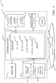
- Fig. 1 illustrates a non-limiting example of a system 10 for operating a vehicle, e.g. a host-vehicle 12.
- the system 10 operates the host-vehicle 12 to avoid picking-up or dropping-off a client 14, i.e. a passenger or customer, at locations (i.e. a pick-up site or a drop-off site) where the ground or surface is considered to be too steeply sloped for easy and/or safe ingress (i.e. entering) or egress (i.e. exiting) of the host-vehicle by the client 14.
- the non-limiting example of Fig. 1 shows the client 14 as being within the host-vehicle 12, possibly preparing to exit the host-vehicle 12, the alternative where the client is outside of the host-vehicle and possibly preparing to enter the host-vehicle is also contemplated.
- the host-vehicle 12 may be characterized as an automated vehicle, and may be referred to by some as an automated-mobility-on-demand (AMOD) type of vehicle.
- AMOD automated-mobility-on-demand
- the term automated vehicle may apply to instances when the host-vehicle 12 is being operated in an automated-mode, i.e. a fully autonomous mode, where a human-operator (not shown) of the host-vehicle 12 may do little more than designate a destination to operate the host-vehicle 12.
- full automation is not a requirement.
- teachings presented herein are useful when the host-vehicle 12 is operated in a manual-mode where the degree or level of automation may be little more than providing an audible or visual guidance to the human-operator who is generally in control of the steering, accelerator, and brakes of the host-vehicle 12.
- the system 10 includes a perception-sensor 16 operable to, among other functions, determine a slope 18 of an area 20 proximate to (i.e. underneath or nearby, e.g. within 75 meters) the host-vehicle 12.
- the perception-sensor 16 may include or consist of, but is not limited to, one or more instances of a camera, a radar-unit, a lidar-unit, or any combination thereof. Examples of these devices that are suitable for use on the host-vehicle 12 are commercially available, as will be recognize by those in the automated vehicle or autonomous vehicle arts.
- the perception-sensor 16 may also include an angle-detector 16A, e.g. a vehicle-angle-detector, that can be used to determine the slope 18 of the area 20.
- the slope 20 may be based on the angle (e.g. pitch-angle, roll-angle, compound-angle) of the host-vehicle 12 and/or the devices (camera, radar-unit, lidar-unit) mounted on the host-vehicle, and may be expressed as an angle relative to the direction of gravity or level, e.g. a plane oriented normal to the direction of gravity.
- the angle-detector 16A may be attached to the frame of the host-vehicle 12, or integrated into the camera, radar-unit, or lidar-unit.
- the slope 20 may be determined or calculated using image interpolation.
- the system 10 also includes vehicle-controls 22 operable to control or actuate, for example, the steering, brakes, and accelerator of the host-vehicle, and thereby control movement of the host-vehicle 12.
- vehicle-controls 22 operable to control or actuate, for example, the steering, brakes, and accelerator of the host-vehicle, and thereby control movement of the host-vehicle 12.
- the means for computer control of these aspects of vehicle operation are known and are commercially available.
- the system 10 also includes a controller-circuit 30 in communication with the perception-sensor 16 via an input 36 and the vehicle-controls 22 via an output 38.
- the communication may be by way of, but not limited to, wires, optical-fiber, or wireless communications.
- the input 36 and the output 38 may be configured to send/receive analog and/or digital signals.
- the controller-circuit 30, hereafter sometimes referred to as the controller 30, may include one or more instances of a processor 32 such as one or more instances of a microprocessor or other control circuitry such as analog and/or digital control circuitry including an application specific integrated circuit (ASIC) for processing data as should be evident to those in the art.
- ASIC application specific integrated circuit
- controller 30 While the system 10 described herein is generally described in terms of having a single instance of the controller 30, it is recognized that the functions of the controller 30 may be shared or distributed among several instances of controllers that are each configured for some specific task. Hereafter, any reference to the controller 30 being configured for something is to also be interpreted as suggesting that the processor 32 may also be configured for the same thing. It is also recognized that there may be multiple instances of processors in any instance of the controller 30.
- the controller 30 may include memory 34, i.e. non-transitory computer-readable storage-medium, including non-volatile memory, such as electrically erasable programmable read-only memory (EEPROM) for storing one or more routines, thresholds, and captured data.
- the memory 34 may be part of the processor 32, or part of the controller 30, or separate from the controller 30 such as remote memory stored in the cloud.
- the one or more routines may be executed by the controller 30 or the processor 32 to perform steps for determining the slope 18 based on signals received by the controller 30 from the perception-sensor 16 as described herein.
- Fig. 2 illustrates a non-limiting example of a scenario 24 where the roadway 26 at a destination has a relatively steep slope, e.g. twenty-five-degrees of angle (25° ⁇ ) with respect to level.
- the client 14 it may be difficult for the client 14 (not shown in Fig. 2 ) to enter or exit the host-vehicle 12 while the host-vehicle 12 is stopped where the slope 18 is relatively steep. Possible reasons include, but are not limited to, the client 14 being aged and/or disabled, and/or the client 14 is carrying multiple packages, and/or the roadway 26 is slippery because of water, ice, or snow.
- the system 10 described herein is an improvement over prior systems in that when the system 10 determines or detects that the slope 18 is relatively steep, the system 10 takes action to find an alternative location for the client 14 to enter or exit the host-vehicle 12, where the slope 18 of the alternative location is more level, i.e. not relatively steep.
- the controller-circuit 30 (or the processor 32) is configured (e.g. programmed) to determine a first-slope 40 of a first-site 42 (i.e. an initial or preferred site, e.g. a spot on the roadway 26 that corresponds to the address of the client) to pick-up or drop-off a client 14 of the host-vehicle 12.
- the first-slope 40 may be merely what is indicated by the angle-detector 16A, or may be based on what is indicated by the angle-detector 16A combined with other information from the camera, radar-unit, and/or lidar-unit, where the information may be collected by the perception-sensor 16 as the host-vehicle 12 approaches the first-site 42.
- the controller-circuit 30 is further configured to compare the first-slope 40 to the slope-threshold 44, e.g. twenty-one-degrees of angle (21° ⁇ ). The comparison may be done using known algorithms (not shown) and/or an arithmetic-logic-unit (not shown) of the controller 30. In response to a determination that the first-slope 40 is steeper than the slope-threshold 44, the controller 30 seeks to select a second-site 46 to pick-up or drop-off the client 14, where the second-site 46 is characterized by a second-slope 48 that is not steeper than the slope-threshold 44.
- the system 10 may use the camera, radar-unit, and/or lidar-unit of the perception-sensor 16 to visually search for or scan for some nearby surface that is less steep.
- a second-site 46 which is a nearby instance of a driveway with access to the roadway 26 can be 'seen' by the perception-sensor 16 from the first-site 42 or as the host-vehicle 12 passed by the end of the driveway.
- a second-slope 48 of the second-site 46 can be estimated using known image/radar-map/lidar cloud-point data processing algorithms.
- the system 10 includes a digital-map 50 ( Fig. 1 ) that may indicate a slope of a location, e.g. the second-slope of the second-site 46, or merely indicate locations where the slope 18 is less steep than the slope-threshold 44.
- the controller-circuit 30 may be configured to access the digital-map 50 to select the second-site 46 in response to the determination that the first-slope 40 is steeper than the slope-threshold 44.
- the controller 30 is further configured to operate the vehicle-controls 22 to move (i.e. drive) the host-vehicle 12 to the second-site 46.
- the angle-detector 16A may again be used to verify the value of the second-slope 48.
- the slope-threshold 44 may be varied in accordance with various ambient conditions. For example, the slope-threshold 44 may be decreased, i.e. a more level site is required, if the ambient lighting is low (e.g. night time), and/or the presence of ice/snow is detected or suspected. For example, the slope-threshold 44 may be varied in accordance with temperature as an ambient temperature below freezing (less than 0°C) may result in water on the ground being frozen. Accordingly, in one embodiment, the system 10 includes a temperature-sensor 52 that indicates an ambient-temperature 54 of the area 20 proximate to the host-vehicle 12. The temperature-sensor may be included in the perception-sensor 16 as suggested by Fig.
- the controller-circuit 30 is configured to adjust the slope-threshold 44 in accordance with the ambient-temperature 54.
- the slope-threshold 44 may be set to twenty-one-degrees of angle (21° ⁇ ) if/when the ambient-temperature 54 is not below freezing (not less than 0°C), and fifteen-degrees of angle (15°L) if/when the ambient-temperature 54 is below freezing (less than 0°C). That is, the controller-circuit 30 may be configured to decrease the slope-threshold 44 in response to a determination that the ambient-temperature 54 has decreased to less than zero-degrees-Celsius (0°C).
- the system 10 may include a leveling-actuator 56 operable to level the host-vehicle 12.
- Leveling the host-vehicle 12 may be of further assistance to the client 14 for entering or exiting the host-vehicle 12.
- the leveling-actuator 56 may include independently operable air-shocks so both the pitch-angle (front/back angle) and/or the roll-angle (side-to-side angle) of the host-vehicle 12 can be adjusted so the host-vehicle 12 is more level even though the ground is not level, i.e. sloped.
- the controller-circuit 30 may be configured to operate the leveling-actuator 56 to level the host-vehicle 12 to pick-up or drop-off the client 14.
- Fig. 3 illustrates a non-limiting example of a method 100 for operating a vehicle, e.g. the host-vehicle 12. It is contemplated that some of the steps of the method 100 shown may be deleted, and others may be added, and/or the steps may be reordered, and the benefits of the system 10 described above will still be realized.
- Step 105 RECEIVE SLOPE INFORMATION, may include receiving from a perception-sensor 16 an indication of a slope 18 of an area 20 proximate to a host-vehicle 12.
- the perception-sensor 16 may include an angle-sensor 16A that, for example, indicates the angle (relative to the direction of gravity) of the frame of host-vehicle 12, or indicates the angle one or more other devices that form the perception-sensor 16 such as, for example, one or more instances of a camera, a radar-unit, and/or a lidar-unit.
- Step 110 DETERMINE FIRST-SLOPE OF FIRST-SITE, may include determining a first-slope 40 of a first-site 42 to pick-up or drop-off a client 14 of the host-vehicle 12 based on the angle indicated by the angle-sensor 16A and/or data/information from the one or more instances of a camera, a radar-unit, and/or a lidar-unit.
- Step 115 DETERMINE AMBIENT-TEMPERATURE, is an optional step that may include receiving from a temperature-sensor 52 an indication of an ambient-temperature 54 of the area 20 proximate to the host-vehicle 12.
- the ambient-temperature may be determined by the controller 30 accessing a weather web-site via a Wi-Fi transceiver (not shown).
- Step 120 may include adjusting the slope-threshold 44 in accordance with detected conditions such as ambient-lighting, the ambient-temperature 54, and/or a physical assessment of the client 14. That is, in the presence of some conditions, it is contemplated that even more level ground is preferred, so the value of the slope-threshold 44 may be decreased from typical.
- the step may include decreasing the slope-threshold 44 in response to a determination that the ambient-temperature 54 has decreased to less than zero-degrees-Celsius (0°C).
- Step 125, FIRST-SLOPE > SLOPE-THRESHOLD? may include comparing by the controller 30 or the processor 32 the numerical value of the first-slope 40 to the numerical value of the slope-threshold 44, where level ground is indicated as having a slope of zero-degrees of angle (0° ⁇ ).
- Step 130, ACCESS DIGITAL-MAP is an optional step may include accessing a digital-map 50 to select the second-site 46 in response to the determination that the first-slope 40 is steeper than the slope-threshold 44.
- the digital-map may be stored in the controller 30 or stored "in the cloud” and accessed via a Wi-Fi or cellular network.
- Step 135, SELECT SECOND-SITE may include in response to a determination that the first-slope 40 is steeper than the slope-threshold 44, selecting a second-site 46 to pick-up or drop-off the client, said second-site 46 characterized by a second-slope 48 that is not steeper than the slope-threshold 44.
- the criteria for selecting the second-site 46 may include, but is not limited to, limiting the distance from the first-site 42 to the second-site 46, or increasing the slope-threshold 44 as the distance to potential candidates for the second-site 46 increases.
- Step 140 OPERATE VEHICLE-CONTROLS, may include operating the vehicle-controls 22 to move the host-vehicle 12 to the second-site 46.
- the client 14 may be informed or authorization by the client 14 may be requested.
- the system 10 may include a communications-device 58 such as speaker/microphone, display/touch-screen, or blue-tooth connection to a smart-phone carried by the client 14 that can communicate to the client 14 why the host-vehicle 12 is moving and/or request permission to execute the move to the second-site 46.
- a communications-device 58 such as speaker/microphone, display/touch-screen, or blue-tooth connection to a smart-phone carried by the client 14 that can communicate to the client 14 why the host-vehicle 12 is moving and/or request permission to execute the move to the second-site 46.
- Step 145 OPERATE LEVELING-ACTUATOR, is an optional step that may include operating a leveling-actuator 56 to level the host-vehicle 12 to pick-up or drop-off the client 14. This may occur at the first-site 42 if the first-slope 40 is less than the slope-threshold 44 or the client 14 refuses the option to move to the second-site 46, or the host-vehicle 12 arrives at the second-site 46.
- a first device 30 that includes one or more processors 32; memory 34; and one or more programs 105-145 stored in memory 34.
- the one or more programs 105-145 including instructions for performing all or part of the method 100.
- a non-transitory computer-readable storage-medium 34 that includes one or more programs 105-145 for execution by one or more processors 32 of a first device 30, the one or more programs 105-145 including instructions which, when executed by the one or more processors 32, cause the first device to perform all or part of the method 100.
- a system 10, a controller 30 and/or a processor 32 for the system 10, and a method 100 of operating the system 10 are provided.
- the system 10 attempts to avoid situations where the client 14 must enter or exit the host-vehicle 12 at locations where the ground under the host-vehicle 12 is so steeply sloped that it may be difficult for the client to safely or easily enter or exit the host-vehicle 12.
Landscapes
- Engineering & Computer Science (AREA)
- Mechanical Engineering (AREA)
- Transportation (AREA)
- Automation & Control Theory (AREA)
- Chemical & Material Sciences (AREA)
- Combustion & Propulsion (AREA)
- Human Computer Interaction (AREA)
- Traffic Control Systems (AREA)
- Control Of Driving Devices And Active Controlling Of Vehicle (AREA)
Abstract
Description
- This disclosure generally relates to a system for operating a vehicle, and more particularly relates to a system that determines a first-slope of a first-site to pick-up or drop-off a client of the host-vehicle, and selects a second-site to pick-up or drop-off the client when the first-slope is steeper than a slope-threshold.
- The present invention will now be described, by way of example with reference to the accompanying drawings, in which:
-
Fig. 1 is a diagram of a system for operating a vehicle in accordance with one embodiment; -
Fig. 2 is a scenario encountered by the system ofFig. 1 in accordance with one embodiment; and -
Fig. 3 is a method of operating the system ofFig. 1 in accordance with one embodiment. - Reference will now be made in detail to embodiments, examples of which are illustrated in the accompanying drawings. In the following detailed description, numerous specific details are set forth in order to provide a thorough understanding of the various described embodiments. However, it will be apparent to one of ordinary skill in the art that the various described embodiments may be practiced without these specific details. In other instances, well-known methods, procedures, components, circuits, and networks have not been described in detail so as not to unnecessarily obscure aspects of the embodiments.
- 'One or more' includes a function being performed by one element, a function being performed by more than one element, e.g., in a distributed fashion, several functions being performed by one element, several functions being performed by several elements, or any combination of the above.
- It will also be understood that, although the terms first, second, etc. are, in some instances, used herein to describe various elements, these elements should not be limited by these terms. These terms are only used to distinguish one element from another. For example, a first contact could be termed a second contact, and, similarly, a second contact could be termed a first contact, without departing from the scope of the various described embodiments. The first contact and the second contact are both contacts, but they are not the same contact.
- The terminology used in the description of the various described embodiments herein is for describing embodiments only and is not intended to be limiting. As used in the description of the various described embodiments and the appended claims, the singular forms "a", "an" and "the" are intended to include the plural forms as well, unless the context clearly indicates otherwise. It will also be understood that the term "and/or" as used herein refers to and encompasses all possible combinations of one or more of the associated listed items. It will be further understood that the terms "includes," "including," "comprises," and/or "comprising," when used in this specification, specify the presence of stated features, integers, steps, operations, elements, and/or components, but do not preclude the presence or addition of one or more other features, integers, steps, operations, elements, components, and/or groups thereof.
- As used herein, the term "if' is, optionally, construed to mean "when" or "upon" or "in response to determining" or "in response to detecting," depending on the context. Similarly, the phrase "if it is determined" or "if [a stated condition or event] is detected" is, optionally, construed to mean "upon determining" or "in response to determining" or "upon detecting [the stated condition or event]" or "in response to detecting [the stated condition or event]," depending on the context.
-
Fig. 1 illustrates a non-limiting example of asystem 10 for operating a vehicle, e.g. a host-vehicle 12. As will be explained in more detail below, thesystem 10 operates the host-vehicle 12 to avoid picking-up or dropping-off a client 14, i.e. a passenger or customer, at locations (i.e. a pick-up site or a drop-off site) where the ground or surface is considered to be too steeply sloped for easy and/or safe ingress (i.e. entering) or egress (i.e. exiting) of the host-vehicle by the client 14. While the non-limiting example ofFig. 1 shows the client 14 as being within the host-vehicle 12, possibly preparing to exit the host-vehicle 12, the alternative where the client is outside of the host-vehicle and possibly preparing to enter the host-vehicle is also contemplated. - The host-
vehicle 12 may be characterized as an automated vehicle, and may be referred to by some as an automated-mobility-on-demand (AMOD) type of vehicle. As used herein, the term automated vehicle may apply to instances when the host-vehicle 12 is being operated in an automated-mode, i.e. a fully autonomous mode, where a human-operator (not shown) of the host-vehicle 12 may do little more than designate a destination to operate the host-vehicle 12. However, full automation is not a requirement. It is contemplated that the teachings presented herein are useful when the host-vehicle 12 is operated in a manual-mode where the degree or level of automation may be little more than providing an audible or visual guidance to the human-operator who is generally in control of the steering, accelerator, and brakes of the host-vehicle 12. - The
system 10 includes a perception-sensor 16 operable to, among other functions, determine aslope 18 of anarea 20 proximate to (i.e. underneath or nearby, e.g. within 75 meters) the host-vehicle 12. The perception-sensor 16 may include or consist of, but is not limited to, one or more instances of a camera, a radar-unit, a lidar-unit, or any combination thereof. Examples of these devices that are suitable for use on the host-vehicle 12 are commercially available, as will be recognize by those in the automated vehicle or autonomous vehicle arts. The perception-sensor 16 may also include an angle-detector 16A, e.g. a vehicle-angle-detector, that can be used to determine theslope 18 of thearea 20. Theslope 20 may be based on the angle (e.g. pitch-angle, roll-angle, compound-angle) of the host-vehicle 12 and/or the devices (camera, radar-unit, lidar-unit) mounted on the host-vehicle, and may be expressed as an angle relative to the direction of gravity or level, e.g. a plane oriented normal to the direction of gravity. By way of example and not limitation, the angle-detector 16A may be attached to the frame of the host-vehicle 12, or integrated into the camera, radar-unit, or lidar-unit. Alternatively, theslope 20 may be determined or calculated using image interpolation. - The
system 10 also includes vehicle-controls 22 operable to control or actuate, for example, the steering, brakes, and accelerator of the host-vehicle, and thereby control movement of the host-vehicle 12. The means for computer control of these aspects of vehicle operation are known and are commercially available. - The
system 10 also includes a controller-circuit 30 in communication with the perception-sensor 16 via aninput 36 and the vehicle-controls 22 via anoutput 38. The communication may be by way of, but not limited to, wires, optical-fiber, or wireless communications. Theinput 36 and theoutput 38 may be configured to send/receive analog and/or digital signals. The controller-circuit 30, hereafter sometimes referred to as thecontroller 30, may include one or more instances of aprocessor 32 such as one or more instances of a microprocessor or other control circuitry such as analog and/or digital control circuitry including an application specific integrated circuit (ASIC) for processing data as should be evident to those in the art. While thesystem 10 described herein is generally described in terms of having a single instance of thecontroller 30, it is recognized that the functions of thecontroller 30 may be shared or distributed among several instances of controllers that are each configured for some specific task. Hereafter, any reference to thecontroller 30 being configured for something is to also be interpreted as suggesting that theprocessor 32 may also be configured for the same thing. It is also recognized that there may be multiple instances of processors in any instance of thecontroller 30. - The
controller 30 may includememory 34, i.e. non-transitory computer-readable storage-medium, including non-volatile memory, such as electrically erasable programmable read-only memory (EEPROM) for storing one or more routines, thresholds, and captured data. Thememory 34 may be part of theprocessor 32, or part of thecontroller 30, or separate from thecontroller 30 such as remote memory stored in the cloud. The one or more routines may be executed by thecontroller 30 or theprocessor 32 to perform steps for determining theslope 18 based on signals received by thecontroller 30 from the perception-sensor 16 as described herein. -
Fig. 2 illustrates a non-limiting example of ascenario 24 where theroadway 26 at a destination has a relatively steep slope, e.g. twenty-five-degrees of angle (25°∟) with respect to level. For any one or more of numerous reasons, it may be difficult for the client 14 (not shown inFig. 2 ) to enter or exit the host-vehicle 12 while the host-vehicle 12 is stopped where theslope 18 is relatively steep. Possible reasons include, but are not limited to, the client 14 being aged and/or disabled, and/or the client 14 is carrying multiple packages, and/or theroadway 26 is slippery because of water, ice, or snow. As will become clear in the description that follows, thesystem 10 described herein is an improvement over prior systems in that when thesystem 10 determines or detects that theslope 18 is relatively steep, thesystem 10 takes action to find an alternative location for the client 14 to enter or exit the host-vehicle 12, where theslope 18 of the alternative location is more level, i.e. not relatively steep. - To this end, the controller-circuit 30 (or the processor 32) is configured (e.g. programmed) to determine a first-
slope 40 of a first-site 42 (i.e. an initial or preferred site, e.g. a spot on theroadway 26 that corresponds to the address of the client) to pick-up or drop-off a client 14 of the host-vehicle 12. The first-slope 40 may be merely what is indicated by the angle-detector 16A, or may be based on what is indicated by the angle-detector 16A combined with other information from the camera, radar-unit, and/or lidar-unit, where the information may be collected by the perception-sensor 16 as the host-vehicle 12 approaches the first-site 42. - The controller-
circuit 30 is further configured to compare the first-slope 40 to the slope-threshold 44, e.g. twenty-one-degrees of angle (21°∟). The comparison may be done using known algorithms (not shown) and/or an arithmetic-logic-unit (not shown) of thecontroller 30. In response to a determination that the first-slope 40 is steeper than the slope-threshold 44, thecontroller 30 seeks to select a second-site 46 to pick-up or drop-off the client 14, where the second-site 46 is characterized by a second-slope 48 that is not steeper than the slope-threshold 44. In one embodiment, thesystem 10 may use the camera, radar-unit, and/or lidar-unit of the perception-sensor 16 to visually search for or scan for some nearby surface that is less steep. In the non-limiting example ofFig. 2 , a second-site 46 which is a nearby instance of a driveway with access to theroadway 26 can be 'seen' by the perception-sensor 16 from the first-site 42 or as the host-vehicle 12 passed by the end of the driveway. Using data from the perception-sensor 16, a second-slope 48 of the second-site 46 can be estimated using known image/radar-map/lidar cloud-point data processing algorithms. - In an alternative embodiment, the
system 10 includes a digital-map 50 (Fig. 1 ) that may indicate a slope of a location, e.g. the second-slope of the second-site 46, or merely indicate locations where theslope 18 is less steep than the slope-threshold 44. Accordingly, the controller-circuit 30 may be configured to access the digital-map 50 to select the second-site 46 in response to the determination that the first-slope 40 is steeper than the slope-threshold 44. Regardless of what process/information is used to select the second-site 46 and determine the second-slope 48, thecontroller 30 is further configured to operate the vehicle-controls 22 to move (i.e. drive) the host-vehicle 12 to the second-site 46. Upon arrival at the second-site 46, it is contemplated that the angle-detector 16A may again be used to verify the value of the second-slope 48. - It is contemplated that the slope-
threshold 44 may be varied in accordance with various ambient conditions. For example, the slope-threshold 44 may be decreased, i.e. a more level site is required, if the ambient lighting is low (e.g. night time), and/or the presence of ice/snow is detected or suspected. For example, the slope-threshold 44 may be varied in accordance with temperature as an ambient temperature below freezing (less than 0°C) may result in water on the ground being frozen. Accordingly, in one embodiment, thesystem 10 includes a temperature-sensor 52 that indicates an ambient-temperature 54 of thearea 20 proximate to the host-vehicle 12. The temperature-sensor may be included in the perception-sensor 16 as suggested byFig. 1 , or may be a remote sensor that is part of a weather-detection-system so the ambient-temperature 54 is communicated to the host-vehicle 12 by way of, for example, a Wi-Fi network or cellular-telephone-network. It follows that the controller-circuit 30 is configured to adjust the slope-threshold 44 in accordance with the ambient-temperature 54. For example, the slope-threshold 44 may be set to twenty-one-degrees of angle (21°∟) if/when the ambient-temperature 54 is not below freezing (not less than 0°C), and fifteen-degrees of angle (15°L) if/when the ambient-temperature 54 is below freezing (less than 0°C). That is, the controller-circuit 30 may be configured to decrease the slope-threshold 44 in response to a determination that the ambient-temperature 54 has decreased to less than zero-degrees-Celsius (0°C). - In addition to checking the
slope 18 and, if necessary or desirable, searching for level ground, thesystem 10 may include a leveling-actuator 56 operable to level the host-vehicle 12. Leveling the host-vehicle 12 may be of further assistance to the client 14 for entering or exiting the host-vehicle 12. By way of example, the leveling-actuator 56 may include independently operable air-shocks so both the pitch-angle (front/back angle) and/or the roll-angle (side-to-side angle) of the host-vehicle 12 can be adjusted so the host-vehicle 12 is more level even though the ground is not level, i.e. sloped. It follows that the controller-circuit 30 may be configured to operate the leveling-actuator 56 to level the host-vehicle 12 to pick-up or drop-off the client 14. -
Fig. 3 illustrates a non-limiting example of amethod 100 for operating a vehicle, e.g. the host-vehicle 12. It is contemplated that some of the steps of themethod 100 shown may be deleted, and others may be added, and/or the steps may be reordered, and the benefits of thesystem 10 described above will still be realized. -
Step 105, RECEIVE SLOPE INFORMATION, may include receiving from a perception-sensor 16 an indication of aslope 18 of anarea 20 proximate to a host-vehicle 12. The perception-sensor 16 may include an angle-sensor 16A that, for example, indicates the angle (relative to the direction of gravity) of the frame of host-vehicle 12, or indicates the angle one or more other devices that form the perception-sensor 16 such as, for example, one or more instances of a camera, a radar-unit, and/or a lidar-unit. -
Step 110, DETERMINE FIRST-SLOPE OF FIRST-SITE, may include determining a first-slope 40 of a first-site 42 to pick-up or drop-off a client 14 of the host-vehicle 12 based on the angle indicated by the angle-sensor 16A and/or data/information from the one or more instances of a camera, a radar-unit, and/or a lidar-unit. -
Step 115, DETERMINE AMBIENT-TEMPERATURE, is an optional step that may include receiving from a temperature-sensor 52 an indication of an ambient-temperature 54 of thearea 20 proximate to the host-vehicle 12. Alternatively, the ambient-temperature may be determined by thecontroller 30 accessing a weather web-site via a Wi-Fi transceiver (not shown). -
Step 120, ADJUST SLOPE-THRESHOLD, may include adjusting the slope-threshold 44 in accordance with detected conditions such as ambient-lighting, the ambient-temperature 54, and/or a physical assessment of the client 14. That is, in the presence of some conditions, it is contemplated that even more level ground is preferred, so the value of the slope-threshold 44 may be decreased from typical. For example, the step may include decreasing the slope-threshold 44 in response to a determination that the ambient-temperature 54 has decreased to less than zero-degrees-Celsius (0°C). -
Step 125, FIRST-SLOPE > SLOPE-THRESHOLD?, may include comparing by thecontroller 30 or theprocessor 32 the numerical value of the first-slope 40 to the numerical value of the slope-threshold 44, where level ground is indicated as having a slope of zero-degrees of angle (0°∟). -
Step 130, ACCESS DIGITAL-MAP, is an optional step may include accessing a digital-map 50 to select the second-site 46 in response to the determination that the first-slope 40 is steeper than the slope-threshold 44. The digital-map may be stored in thecontroller 30 or stored "in the cloud" and accessed via a Wi-Fi or cellular network. -
Step 135, SELECT SECOND-SITE, may include in response to a determination that the first-slope 40 is steeper than the slope-threshold 44, selecting a second-site 46 to pick-up or drop-off the client, said second-site 46 characterized by a second-slope 48 that is not steeper than the slope-threshold 44. The criteria for selecting the second-site 46 may include, but is not limited to, limiting the distance from the first-site 42 to the second-site 46, or increasing the slope-threshold 44 as the distance to potential candidates for the second-site 46 increases. -
Step 140, OPERATE VEHICLE-CONTROLS, may include operating the vehicle-controls 22 to move the host-vehicle 12 to the second-site 46. As part of initiating the move to the second-site 46, the client 14 may be informed or authorization by the client 14 may be requested. Accordingly, thesystem 10 may include a communications-device 58 such as speaker/microphone, display/touch-screen, or blue-tooth connection to a smart-phone carried by the client 14 that can communicate to the client 14 why the host-vehicle 12 is moving and/or request permission to execute the move to the second-site 46. -
Step 145, OPERATE LEVELING-ACTUATOR, is an optional step that may include operating a leveling-actuator 56 to level the host-vehicle 12 to pick-up or drop-off the client 14. This may occur at the first-site 42 if the first-slope 40 is less than the slope-threshold 44 or the client 14 refuses the option to move to the second-site 46, or the host-vehicle 12 arrives at the second-site 46. - Described herein is a
first device 30 that includes one ormore processors 32;memory 34; and one or more programs 105-145 stored inmemory 34. The one or more programs 105-145 including instructions for performing all or part of themethod 100. Also, described herein is a non-transitory computer-readable storage-medium 34 that includes one or more programs 105-145 for execution by one ormore processors 32 of afirst device 30, the one or more programs 105-145 including instructions which, when executed by the one ormore processors 32, cause the first device to perform all or part of themethod 100. - Accordingly, a
system 10, acontroller 30 and/or aprocessor 32 for thesystem 10, and amethod 100 of operating thesystem 10 are provided. Thesystem 10 attempts to avoid situations where the client 14 must enter or exit the host-vehicle 12 at locations where the ground under the host-vehicle 12 is so steeply sloped that it may be difficult for the client to safely or easily enter or exit the host-vehicle 12. - While this invention has been described in terms of the preferred embodiments thereof, it is not intended to be so limited, but rather only to the extent set forth in the claims that follow.
Claims (15)
- A system (10) for operating a vehicle, said system (10) comprising:a perception-sensor (16) operable to determine a slope of an area (20) proximate to a host-vehicle (12);vehicle-controls (22) operable to control movement of the host-vehicle (12); anda controller-circuit (30) in communication with the perception-sensor (16) and the vehicle-controls (22), said controller-circuit (30) configured todetermine a first-slope (40) of a first-site (42) to pick-up or drop-off a client (14) of the host-vehicle (12);compare the first-slope (40) to a slope-threshold (44);in response to a determination that the first-slope (40) is steeper than the slope-threshold (44), select a second-site (46) to pick-up or drop-off the client (14), said second-site (46) characterized by a second-slope (48) that is not steeper than the slope-threshold (44); andoperate the vehicle-controls (22) to move the host-vehicle (12) to the second-site (46).
- The system (10) in accordance with claim 1, wherein the system (10) includes a temperature-sensor (52) that indicates an ambient-temperature (54) of the area (20) proximate to the host-vehicle (12); and the controller-circuit (30) is configured to adjust the slope-threshold (44) in accordance with the ambient-temperature (54).
- The system (10) in accordance with claim 2, wherein controller-circuit (30) is configured to decrease the slope-threshold (44) in response to a determination that the ambient-temperature (54) has decreased to less than zero-degrees-Celsius (0°C).
- The system (10) in accordance with any of the previous claims, wherein the system (10) includes a digital-map (50) that indicates a slope of a location; and the controller-circuit (30) is configured to access the digital-map (50) to select the second-site (46) in response to the determination that the first-slope (40) is steeper than the slope-threshold (44).
- The system (10) in accordance with any of the previous claims, wherein the system (10) includes a leveling-actuator (56) operable to level the host-vehicle (12); and the controller-circuit (30) is configured to operate the leveling-actuator (56) to level the host-vehicle (12) to pick-up or drop-off the client (14).
- A controller-circuit (30) for operating a vehicle, said system (10) comprising:an input (36) configured to communicate with a perception-sensor (16) operable to determine a slope of an area (20) proximate to a host-vehicle (12);an output (38) configured to communicate with vehicle-controls (22) of the host-vehicle (12), said vehicle-controls (22) operable to control movement of the host-vehicle (12); anda processor (32) in communication with the perception-sensor (16), said processor (32) configured todetermine a first-slope (40) of a first-site (42) to pick-up or drop-off a client (14) of the host-vehicle (12);compare the first-slope (40) to a slope-threshold (44);in response to a determination that the first-slope (40) is steeper than the slope-threshold (44), select a second-site (46) to pick-up or drop-off the client (14), said second-site (46) characterized by a second-slope (48) that is not steeper than the slope-threshold (44); andoperate the vehicle-controls (22) to move the host-vehicle (12) to the second-site (46).
- The controller-circuit (30) in accordance with claim 6, wherein the processor (32) is configured to communicate with a temperature-sensor (52) that indicates an ambient-temperature (54) of the area (20) proximate to the host-vehicle (12); and the processor (32) is configured to adjust the slope-threshold (44) in accordance with the ambient-temperature (54).
- The controller-circuit (30) in accordance with claim 7, wherein processor (32) is configured to decrease the slope-threshold (44) in response to a determination that the ambient-temperature (54) has decreased to less than zero-degrees-Celsius (0°C).
- The controller-circuit (30) in accordance with any of the previous claims, wherein the processor (32) is configured to communicate with a digital-map (50) that indicates a slope of a location; and the processor (32) is configured to access the digital-map (50) to select the second-site (46) in response to the determination that the first-slope (40) is steeper than the slope-threshold (44).
- A method (100) for operating a vehicle, said system (10) comprising:receiving (105) from a perception-sensor (16) an indication of a slope of an area (20) proximate to a host-vehicle (12); anddetermining (110) a first-slope (40) of a first-site (42) to pick-up or drop-off a client (14) of the host-vehicle (12);comparing (125) the first-slope (40) to a slope-threshold (44);in response to a determination that the first-slope (40) is steeper than the slope-threshold (44), selecting (135) a second-site (46) to pick-up or drop-off the client (14), said second-site (46) characterized by a second-slope (48) that is not steeper than the slope-threshold (44); andoperating (140) the vehicle-controls (22) to move the host-vehicle (12) to the second-site (46).
- The method (100) in accordance with claim 10, wherein the method (100) includes receiving (115) from a temperature-sensor (52) an indication of an ambient-temperature (54) of the area (20) proximate to the host-vehicle (12); and
adjusting (120) the slope-threshold (44) in accordance with the ambient-temperature (54). - The method (100) in accordance with claim 11, wherein method (100) includes decreasing (120) the slope-threshold (44) in response to a determination that the ambient-temperature (54) has decreased to less than zero-degrees-Celsius (0°C).
- The method (100) in accordance with any of the previous claims, wherein the method (100) includes
accessing (130) a digital-map (50) to select the second-site (46) in response to the determination that the first-slope (40) is steeper than the slope-threshold (44). - A first device (30) comprising:one or more processors (32);memory (34); andone or more programs (105-145) stored in memory (34), the one or more programs (105-145) including instructions for performing the method (100) of any one of claims 10-13.
- A non-transitory computer-readable storage-medium (34) comprising one or more programs (105-145) for execution by one or more processors (32) of a first device (30), the one or more programs (105-145) including instructions which, when executed by the one or more processors (32), cause the first device (30) to perform the method (100) of any one of claims 10-13.
Applications Claiming Priority (2)
| Application Number | Priority Date | Filing Date | Title |
|---|---|---|---|
| US201862746888P | 2018-10-17 | 2018-10-17 | |
| US16/165,068 US10843700B2 (en) | 2018-10-17 | 2018-10-19 | Vehicle system and method for steep slope site avoidance |
Publications (2)
| Publication Number | Publication Date |
|---|---|
| EP3640110A1 true EP3640110A1 (en) | 2020-04-22 |
| EP3640110B1 EP3640110B1 (en) | 2022-06-08 |
Family
ID=68208255
Family Applications (1)
| Application Number | Title | Priority Date | Filing Date |
|---|---|---|---|
| EP19201704.4A Active EP3640110B1 (en) | 2018-10-17 | 2019-10-07 | Vehicle system and method for steep slope pick-up and drop-off site avoidance |
Country Status (3)
| Country | Link |
|---|---|
| US (1) | US10843700B2 (en) |
| EP (1) | EP3640110B1 (en) |
| CN (1) | CN111055836B (en) |
Citations (4)
| Publication number | Priority date | Publication date | Assignee | Title |
|---|---|---|---|---|
| US20140297116A1 (en) * | 2013-03-15 | 2014-10-02 | Levant Power Corporation | Self-driving vehicle with integrated active suspension |
| US20170090480A1 (en) * | 2015-09-24 | 2017-03-30 | Uber Technologies, Inc. | Autonomous vehicle operated with safety augmentation |
| WO2017205822A1 (en) * | 2016-05-27 | 2017-11-30 | Uber Technologies, Inc. | Facilitating rider pick-up for a self-driving vehicle |
| US20180244278A1 (en) * | 2017-02-27 | 2018-08-30 | GM Global Technology Operations LLC | Methods and systems for proactively estimating road surface friction coefficient |
Family Cites Families (13)
| Publication number | Priority date | Publication date | Assignee | Title |
|---|---|---|---|---|
| JP2008143430A (en) * | 2006-12-12 | 2008-06-26 | Toyota Motor Corp | Parking assistance device |
| JP5330812B2 (en) * | 2008-11-20 | 2013-10-30 | トヨタ自動車株式会社 | Hybrid vehicle |
| US9733096B2 (en) * | 2015-06-22 | 2017-08-15 | Waymo Llc | Determining pickup and destination locations for autonomous vehicles |
| CN205615420U (en) * | 2016-05-11 | 2016-10-05 | 江西科技学院 | Shuttle bus tail -gate footboard that stretches out and draws back |
| JP6458792B2 (en) * | 2016-11-04 | 2019-01-30 | 本田技研工業株式会社 | Vehicle control system, vehicle control method, and vehicle control program |
| KR101982774B1 (en) * | 2016-11-29 | 2019-05-27 | 엘지전자 주식회사 | Autonomous Vehicle |
| EP3552161A4 (en) * | 2016-12-06 | 2019-10-16 | Nissan North America, Inc. | GENERATION OF SOLUTION DATA FOR AUTONOMOUS VEHICLES TO NEGOTIATE PROBLEM SITUATIONS |
| US20180211540A1 (en) * | 2017-01-23 | 2018-07-26 | Delphi Technologies, Inc. | Automated vehicle transportation system for multiple-segment ground-transportation |
| US11142442B2 (en) * | 2017-02-10 | 2021-10-12 | Arrow Acquisition, Llc | System and method for dynamically controlling the stability of an industrial vehicle |
| US10025316B1 (en) * | 2017-03-23 | 2018-07-17 | Delphi Technologies, Inc. | Automated vehicle safe stop zone use notification system |
| EP3606797B1 (en) * | 2017-04-03 | 2022-11-02 | Motional AD LLC | Processing a request signal regarding operation of an autonomous vehicle |
| US10835428B2 (en) * | 2017-07-21 | 2020-11-17 | New Flyer Industries Canada Ulc | Integrated systems for passenger bus |
| US10576839B2 (en) * | 2018-08-01 | 2020-03-03 | Toyota Motor Engineering & Manufacturing North America, Inc. | Motor lock overheat mitigation control for autonomous vehicles |
-
2018
- 2018-10-19 US US16/165,068 patent/US10843700B2/en active Active
-
2019
- 2019-10-07 EP EP19201704.4A patent/EP3640110B1/en active Active
- 2019-10-16 CN CN201910983108.XA patent/CN111055836B/en active Active
Patent Citations (4)
| Publication number | Priority date | Publication date | Assignee | Title |
|---|---|---|---|---|
| US20140297116A1 (en) * | 2013-03-15 | 2014-10-02 | Levant Power Corporation | Self-driving vehicle with integrated active suspension |
| US20170090480A1 (en) * | 2015-09-24 | 2017-03-30 | Uber Technologies, Inc. | Autonomous vehicle operated with safety augmentation |
| WO2017205822A1 (en) * | 2016-05-27 | 2017-11-30 | Uber Technologies, Inc. | Facilitating rider pick-up for a self-driving vehicle |
| US20180244278A1 (en) * | 2017-02-27 | 2018-08-30 | GM Global Technology Operations LLC | Methods and systems for proactively estimating road surface friction coefficient |
Also Published As
| Publication number | Publication date |
|---|---|
| US20200122738A1 (en) | 2020-04-23 |
| CN111055836A (en) | 2020-04-24 |
| CN111055836B (en) | 2023-03-28 |
| EP3640110B1 (en) | 2022-06-08 |
| US10843700B2 (en) | 2020-11-24 |
Similar Documents
| Publication | Publication Date | Title |
|---|---|---|
| US12013694B2 (en) | Operation-security system for an automated vehicle | |
| CN107430817B (en) | Path search device, control method, and non-transitory computer-readable medium | |
| US10217364B2 (en) | Lane assistance system responsive to extremely fast approaching vehicles | |
| JP2023017824A (en) | Controller | |
| US20180304887A1 (en) | Method and device for reducing a risk of a collision of a motor vehicle with an object | |
| CN111063188B (en) | Distributed route determination system | |
| EP3398824A1 (en) | Automatic braking system and method for operating an automatic braking system | |
| JP2019121040A (en) | Parking control device, vehicle control device and parking control method | |
| KR102387774B1 (en) | Variable range and frame-rate radar operation for automated vehicles | |
| CN114758527B (en) | Vehicle perception data collection system and method | |
| CN109219536A (en) | V2X Object Location Verification System for Automated Vehicles | |
| WO2017210023A1 (en) | Lane management system for an automated vehicle | |
| US10848718B2 (en) | Vehicle sensor configuration based on map data | |
| US11052912B2 (en) | Device and method for assisting with driving a motor vehicle | |
| EP3517380B1 (en) | Travel control method and travel control apparatus for a vehicle | |
| US10884418B2 (en) | Vehicle route planning based on instances of other vehicles stopping automated operation | |
| EP3640121A1 (en) | Vehicle lane-bias system and method | |
| EP3633321A1 (en) | Lane assignment system | |
| EP3640110B1 (en) | Vehicle system and method for steep slope pick-up and drop-off site avoidance | |
| JP7240855B2 (en) | Information processing device and information processing method | |
| CN106627576B (en) | Method for controlling a vehicle according to a destination type | |
| JPWO2019239471A1 (en) | Driving support device, driving support system, and driving support method | |
| CN109774705B (en) | Object detector configuration for human override based on automated vehicle control | |
| US11143760B2 (en) | Object-detector configuration based on human-override of automated vehicle control | |
| CN114155732A (en) | Vehicle surrounding obstacle monitoring method, electronic device, and storage medium |
Legal Events
| Date | Code | Title | Description |
|---|---|---|---|
| PUAI | Public reference made under article 153(3) epc to a published international application that has entered the european phase |
Free format text: ORIGINAL CODE: 0009012 |
|
| STAA | Information on the status of an ep patent application or granted ep patent |
Free format text: STATUS: THE APPLICATION HAS BEEN PUBLISHED |
|
| AK | Designated contracting states |
Kind code of ref document: A1 Designated state(s): AL AT BE BG CH CY CZ DE DK EE ES FI FR GB GR HR HU IE IS IT LI LT LU LV MC MK MT NL NO PL PT RO RS SE SI SK SM TR |
|
| AX | Request for extension of the european patent |
Extension state: BA ME |
|
| STAA | Information on the status of an ep patent application or granted ep patent |
Free format text: STATUS: REQUEST FOR EXAMINATION WAS MADE |
|
| 17P | Request for examination filed |
Effective date: 20200917 |
|
| RBV | Designated contracting states (corrected) |
Designated state(s): AL AT BE BG CH CY CZ DE DK EE ES FI FR GB GR HR HU IE IS IT LI LT LU LV MC MK MT NL NO PL PT RO RS SE SI SK SM TR |
|
| GRAP | Despatch of communication of intention to grant a patent |
Free format text: ORIGINAL CODE: EPIDOSNIGR1 |
|
| STAA | Information on the status of an ep patent application or granted ep patent |
Free format text: STATUS: GRANT OF PATENT IS INTENDED |
|
| RIC1 | Information provided on ipc code assigned before grant |
Ipc: B60W 60/00 20200101AFI20220127BHEP |
|
| INTG | Intention to grant announced |
Effective date: 20220218 |
|
| GRAS | Grant fee paid |
Free format text: ORIGINAL CODE: EPIDOSNIGR3 |
|
| GRAA | (expected) grant |
Free format text: ORIGINAL CODE: 0009210 |
|
| STAA | Information on the status of an ep patent application or granted ep patent |
Free format text: STATUS: THE PATENT HAS BEEN GRANTED |
|
| AK | Designated contracting states |
Kind code of ref document: B1 Designated state(s): AL AT BE BG CH CY CZ DE DK EE ES FI FR GB GR HR HU IE IS IT LI LT LU LV MC MK MT NL NO PL PT RO RS SE SI SK SM TR |
|
| REG | Reference to a national code |
Ref country code: AT Ref legal event code: REF Ref document number: 1496742 Country of ref document: AT Kind code of ref document: T Effective date: 20220615 Ref country code: CH Ref legal event code: EP |
|
| REG | Reference to a national code |
Ref country code: DE Ref legal event code: R096 Ref document number: 602019015619 Country of ref document: DE |
|
| REG | Reference to a national code |
Ref country code: IE Ref legal event code: FG4D |
|
| REG | Reference to a national code |
Ref country code: LT Ref legal event code: MG9D |
|
| REG | Reference to a national code |
Ref country code: NL Ref legal event code: MP Effective date: 20220608 |
|
| PG25 | Lapsed in a contracting state [announced via postgrant information from national office to epo] |
Ref country code: SE Free format text: LAPSE BECAUSE OF FAILURE TO SUBMIT A TRANSLATION OF THE DESCRIPTION OR TO PAY THE FEE WITHIN THE PRESCRIBED TIME-LIMIT Effective date: 20220608 Ref country code: NO Free format text: LAPSE BECAUSE OF FAILURE TO SUBMIT A TRANSLATION OF THE DESCRIPTION OR TO PAY THE FEE WITHIN THE PRESCRIBED TIME-LIMIT Effective date: 20220908 Ref country code: LT Free format text: LAPSE BECAUSE OF FAILURE TO SUBMIT A TRANSLATION OF THE DESCRIPTION OR TO PAY THE FEE WITHIN THE PRESCRIBED TIME-LIMIT Effective date: 20220608 Ref country code: HR Free format text: LAPSE BECAUSE OF FAILURE TO SUBMIT A TRANSLATION OF THE DESCRIPTION OR TO PAY THE FEE WITHIN THE PRESCRIBED TIME-LIMIT Effective date: 20220608 Ref country code: GR Free format text: LAPSE BECAUSE OF FAILURE TO SUBMIT A TRANSLATION OF THE DESCRIPTION OR TO PAY THE FEE WITHIN THE PRESCRIBED TIME-LIMIT Effective date: 20220909 Ref country code: FI Free format text: LAPSE BECAUSE OF FAILURE TO SUBMIT A TRANSLATION OF THE DESCRIPTION OR TO PAY THE FEE WITHIN THE PRESCRIBED TIME-LIMIT Effective date: 20220608 Ref country code: ES Free format text: LAPSE BECAUSE OF FAILURE TO SUBMIT A TRANSLATION OF THE DESCRIPTION OR TO PAY THE FEE WITHIN THE PRESCRIBED TIME-LIMIT Effective date: 20220608 Ref country code: BG Free format text: LAPSE BECAUSE OF FAILURE TO SUBMIT A TRANSLATION OF THE DESCRIPTION OR TO PAY THE FEE WITHIN THE PRESCRIBED TIME-LIMIT Effective date: 20220908 |
|
| REG | Reference to a national code |
Ref country code: AT Ref legal event code: MK05 Ref document number: 1496742 Country of ref document: AT Kind code of ref document: T Effective date: 20220608 |
|
| PG25 | Lapsed in a contracting state [announced via postgrant information from national office to epo] |
Ref country code: RS Free format text: LAPSE BECAUSE OF FAILURE TO SUBMIT A TRANSLATION OF THE DESCRIPTION OR TO PAY THE FEE WITHIN THE PRESCRIBED TIME-LIMIT Effective date: 20220608 Ref country code: LV Free format text: LAPSE BECAUSE OF FAILURE TO SUBMIT A TRANSLATION OF THE DESCRIPTION OR TO PAY THE FEE WITHIN THE PRESCRIBED TIME-LIMIT Effective date: 20220608 |
|
| PG25 | Lapsed in a contracting state [announced via postgrant information from national office to epo] |
Ref country code: NL Free format text: LAPSE BECAUSE OF FAILURE TO SUBMIT A TRANSLATION OF THE DESCRIPTION OR TO PAY THE FEE WITHIN THE PRESCRIBED TIME-LIMIT Effective date: 20220608 |
|
| PG25 | Lapsed in a contracting state [announced via postgrant information from national office to epo] |
Ref country code: SM Free format text: LAPSE BECAUSE OF FAILURE TO SUBMIT A TRANSLATION OF THE DESCRIPTION OR TO PAY THE FEE WITHIN THE PRESCRIBED TIME-LIMIT Effective date: 20220608 Ref country code: SK Free format text: LAPSE BECAUSE OF FAILURE TO SUBMIT A TRANSLATION OF THE DESCRIPTION OR TO PAY THE FEE WITHIN THE PRESCRIBED TIME-LIMIT Effective date: 20220608 Ref country code: RO Free format text: LAPSE BECAUSE OF FAILURE TO SUBMIT A TRANSLATION OF THE DESCRIPTION OR TO PAY THE FEE WITHIN THE PRESCRIBED TIME-LIMIT Effective date: 20220608 Ref country code: PT Free format text: LAPSE BECAUSE OF FAILURE TO SUBMIT A TRANSLATION OF THE DESCRIPTION OR TO PAY THE FEE WITHIN THE PRESCRIBED TIME-LIMIT Effective date: 20221010 Ref country code: EE Free format text: LAPSE BECAUSE OF FAILURE TO SUBMIT A TRANSLATION OF THE DESCRIPTION OR TO PAY THE FEE WITHIN THE PRESCRIBED TIME-LIMIT Effective date: 20220608 Ref country code: CZ Free format text: LAPSE BECAUSE OF FAILURE TO SUBMIT A TRANSLATION OF THE DESCRIPTION OR TO PAY THE FEE WITHIN THE PRESCRIBED TIME-LIMIT Effective date: 20220608 Ref country code: AT Free format text: LAPSE BECAUSE OF FAILURE TO SUBMIT A TRANSLATION OF THE DESCRIPTION OR TO PAY THE FEE WITHIN THE PRESCRIBED TIME-LIMIT Effective date: 20220608 |
|
| PG25 | Lapsed in a contracting state [announced via postgrant information from national office to epo] |
Ref country code: PL Free format text: LAPSE BECAUSE OF FAILURE TO SUBMIT A TRANSLATION OF THE DESCRIPTION OR TO PAY THE FEE WITHIN THE PRESCRIBED TIME-LIMIT Effective date: 20220608 Ref country code: IS Free format text: LAPSE BECAUSE OF FAILURE TO SUBMIT A TRANSLATION OF THE DESCRIPTION OR TO PAY THE FEE WITHIN THE PRESCRIBED TIME-LIMIT Effective date: 20221008 |
|
| REG | Reference to a national code |
Ref country code: DE Ref legal event code: R097 Ref document number: 602019015619 Country of ref document: DE |
|
| RAP4 | Party data changed (patent owner data changed or rights of a patent transferred) |
Owner name: APTIV TECHNOLOGIES LIMITED |
|
| PG25 | Lapsed in a contracting state [announced via postgrant information from national office to epo] |
Ref country code: AL Free format text: LAPSE BECAUSE OF FAILURE TO SUBMIT A TRANSLATION OF THE DESCRIPTION OR TO PAY THE FEE WITHIN THE PRESCRIBED TIME-LIMIT Effective date: 20220608 |
|
| PLBE | No opposition filed within time limit |
Free format text: ORIGINAL CODE: 0009261 |
|
| STAA | Information on the status of an ep patent application or granted ep patent |
Free format text: STATUS: NO OPPOSITION FILED WITHIN TIME LIMIT |
|
| PG25 | Lapsed in a contracting state [announced via postgrant information from national office to epo] |
Ref country code: DK Free format text: LAPSE BECAUSE OF FAILURE TO SUBMIT A TRANSLATION OF THE DESCRIPTION OR TO PAY THE FEE WITHIN THE PRESCRIBED TIME-LIMIT Effective date: 20220608 |
|
| 26N | No opposition filed |
Effective date: 20230310 |
|
| PG25 | Lapsed in a contracting state [announced via postgrant information from national office to epo] |
Ref country code: SI Free format text: LAPSE BECAUSE OF FAILURE TO SUBMIT A TRANSLATION OF THE DESCRIPTION OR TO PAY THE FEE WITHIN THE PRESCRIBED TIME-LIMIT Effective date: 20220608 Ref country code: MC Free format text: LAPSE BECAUSE OF FAILURE TO SUBMIT A TRANSLATION OF THE DESCRIPTION OR TO PAY THE FEE WITHIN THE PRESCRIBED TIME-LIMIT Effective date: 20220608 |
|
| REG | Reference to a national code |
Ref country code: CH Ref legal event code: PL |
|
| P01 | Opt-out of the competence of the unified patent court (upc) registered |
Effective date: 20230424 |
|
| REG | Reference to a national code |
Ref country code: BE Ref legal event code: MM Effective date: 20221031 |
|
| PG25 | Lapsed in a contracting state [announced via postgrant information from national office to epo] |
Ref country code: LU Free format text: LAPSE BECAUSE OF NON-PAYMENT OF DUE FEES Effective date: 20221007 |
|
| PG25 | Lapsed in a contracting state [announced via postgrant information from national office to epo] |
Ref country code: LI Free format text: LAPSE BECAUSE OF NON-PAYMENT OF DUE FEES Effective date: 20221031 Ref country code: CH Free format text: LAPSE BECAUSE OF NON-PAYMENT OF DUE FEES Effective date: 20221031 |
|
| PG25 | Lapsed in a contracting state [announced via postgrant information from national office to epo] |
Ref country code: BE Free format text: LAPSE BECAUSE OF NON-PAYMENT OF DUE FEES Effective date: 20221031 |
|
| PG25 | Lapsed in a contracting state [announced via postgrant information from national office to epo] |
Ref country code: IE Free format text: LAPSE BECAUSE OF NON-PAYMENT OF DUE FEES Effective date: 20221007 |
|
| PG25 | Lapsed in a contracting state [announced via postgrant information from national office to epo] |
Ref country code: IT Free format text: LAPSE BECAUSE OF FAILURE TO SUBMIT A TRANSLATION OF THE DESCRIPTION OR TO PAY THE FEE WITHIN THE PRESCRIBED TIME-LIMIT Effective date: 20220608 |
|
| PG25 | Lapsed in a contracting state [announced via postgrant information from national office to epo] |
Ref country code: HU Free format text: LAPSE BECAUSE OF FAILURE TO SUBMIT A TRANSLATION OF THE DESCRIPTION OR TO PAY THE FEE WITHIN THE PRESCRIBED TIME-LIMIT; INVALID AB INITIO Effective date: 20191007 |
|
| PG25 | Lapsed in a contracting state [announced via postgrant information from national office to epo] |
Ref country code: CY Free format text: LAPSE BECAUSE OF FAILURE TO SUBMIT A TRANSLATION OF THE DESCRIPTION OR TO PAY THE FEE WITHIN THE PRESCRIBED TIME-LIMIT Effective date: 20220608 |
|
| PG25 | Lapsed in a contracting state [announced via postgrant information from national office to epo] |
Ref country code: MK Free format text: LAPSE BECAUSE OF FAILURE TO SUBMIT A TRANSLATION OF THE DESCRIPTION OR TO PAY THE FEE WITHIN THE PRESCRIBED TIME-LIMIT Effective date: 20220608 |
|
| PG25 | Lapsed in a contracting state [announced via postgrant information from national office to epo] |
Ref country code: MT Free format text: LAPSE BECAUSE OF FAILURE TO SUBMIT A TRANSLATION OF THE DESCRIPTION OR TO PAY THE FEE WITHIN THE PRESCRIBED TIME-LIMIT Effective date: 20220608 |
|
| PG25 | Lapsed in a contracting state [announced via postgrant information from national office to epo] |
Ref country code: BG Free format text: LAPSE BECAUSE OF FAILURE TO SUBMIT A TRANSLATION OF THE DESCRIPTION OR TO PAY THE FEE WITHIN THE PRESCRIBED TIME-LIMIT Effective date: 20220608 |
|
| PG25 | Lapsed in a contracting state [announced via postgrant information from national office to epo] |
Ref country code: BG Free format text: LAPSE BECAUSE OF FAILURE TO SUBMIT A TRANSLATION OF THE DESCRIPTION OR TO PAY THE FEE WITHIN THE PRESCRIBED TIME-LIMIT Effective date: 20220608 |
|
| REG | Reference to a national code |
Ref country code: DE Ref legal event code: R081 Ref document number: 602019015619 Country of ref document: DE Owner name: APTIV TECHNOLOGIES AG, CH Free format text: FORMER OWNER: APTIV TECHNOLOGIES LIMITED, ST. MICHAEL, BB |
|
| PGFP | Annual fee paid to national office [announced via postgrant information from national office to epo] |
Ref country code: GB Payment date: 20250924 Year of fee payment: 7 |
|
| PGFP | Annual fee paid to national office [announced via postgrant information from national office to epo] |
Ref country code: FR Payment date: 20250910 Year of fee payment: 7 |
|
| PG25 | Lapsed in a contracting state [announced via postgrant information from national office to epo] |
Ref country code: TR Free format text: LAPSE BECAUSE OF FAILURE TO SUBMIT A TRANSLATION OF THE DESCRIPTION OR TO PAY THE FEE WITHIN THE PRESCRIBED TIME-LIMIT Effective date: 20220608 |
|
| PGFP | Annual fee paid to national office [announced via postgrant information from national office to epo] |
Ref country code: DE Payment date: 20250917 Year of fee payment: 7 |