EP3640074A1 - An electric power system - Google Patents
An electric power system Download PDFInfo
- Publication number
- EP3640074A1 EP3640074A1 EP18200712.0A EP18200712A EP3640074A1 EP 3640074 A1 EP3640074 A1 EP 3640074A1 EP 18200712 A EP18200712 A EP 18200712A EP 3640074 A1 EP3640074 A1 EP 3640074A1
- Authority
- EP
- European Patent Office
- Prior art keywords
- electric
- adas
- electric power
- power source
- power system
- Prior art date
- Legal status (The legal status is an assumption and is not a legal conclusion. Google has not performed a legal analysis and makes no representation as to the accuracy of the status listed.)
- Granted
Links
Images



Classifications
-
- B—PERFORMING OPERATIONS; TRANSPORTING
- B62—LAND VEHICLES FOR TRAVELLING OTHERWISE THAN ON RAILS
- B62D—MOTOR VEHICLES; TRAILERS
- B62D1/00—Steering controls, i.e. means for initiating a change of direction of the vehicle
- B62D1/02—Steering controls, i.e. means for initiating a change of direction of the vehicle vehicle-mounted
- B62D1/16—Steering columns
- B62D1/18—Steering columns yieldable or adjustable, e.g. tiltable
- B62D1/184—Mechanisms for locking columns at selected positions
-
- B—PERFORMING OPERATIONS; TRANSPORTING
- B60—VEHICLES IN GENERAL
- B60L—PROPULSION OF ELECTRICALLY-PROPELLED VEHICLES; SUPPLYING ELECTRIC POWER FOR AUXILIARY EQUIPMENT OF ELECTRICALLY-PROPELLED VEHICLES; ELECTRODYNAMIC BRAKE SYSTEMS FOR VEHICLES IN GENERAL; MAGNETIC SUSPENSION OR LEVITATION FOR VEHICLES; MONITORING OPERATING VARIABLES OF ELECTRICALLY-PROPELLED VEHICLES; ELECTRIC SAFETY DEVICES FOR ELECTRICALLY-PROPELLED VEHICLES
- B60L1/00—Supplying electric power to auxiliary equipment of vehicles
- B60L1/003—Supplying electric power to auxiliary equipment of vehicles to auxiliary motors, e.g. for pumps, compressors
-
- B—PERFORMING OPERATIONS; TRANSPORTING
- B60—VEHICLES IN GENERAL
- B60L—PROPULSION OF ELECTRICALLY-PROPELLED VEHICLES; SUPPLYING ELECTRIC POWER FOR AUXILIARY EQUIPMENT OF ELECTRICALLY-PROPELLED VEHICLES; ELECTRODYNAMIC BRAKE SYSTEMS FOR VEHICLES IN GENERAL; MAGNETIC SUSPENSION OR LEVITATION FOR VEHICLES; MONITORING OPERATING VARIABLES OF ELECTRICALLY-PROPELLED VEHICLES; ELECTRIC SAFETY DEVICES FOR ELECTRICALLY-PROPELLED VEHICLES
- B60L3/00—Electric devices on electrically-propelled vehicles for safety purposes; Monitoring operating variables, e.g. speed, deceleration or energy consumption
- B60L3/0092—Electric devices on electrically-propelled vehicles for safety purposes; Monitoring operating variables, e.g. speed, deceleration or energy consumption with use of redundant elements for safety purposes
-
- B—PERFORMING OPERATIONS; TRANSPORTING
- B60—VEHICLES IN GENERAL
- B60R—VEHICLES, VEHICLE FITTINGS, OR VEHICLE PARTS, NOT OTHERWISE PROVIDED FOR
- B60R16/00—Electric or fluid circuits specially adapted for vehicles and not otherwise provided for; Arrangement of elements of electric or fluid circuits specially adapted for vehicles and not otherwise provided for
- B60R16/02—Electric or fluid circuits specially adapted for vehicles and not otherwise provided for; Arrangement of elements of electric or fluid circuits specially adapted for vehicles and not otherwise provided for electric constitutive elements
- B60R16/03—Electric or fluid circuits specially adapted for vehicles and not otherwise provided for; Arrangement of elements of electric or fluid circuits specially adapted for vehicles and not otherwise provided for electric constitutive elements for supply of electrical power to vehicle subsystems or for
- B60R16/033—Electric or fluid circuits specially adapted for vehicles and not otherwise provided for; Arrangement of elements of electric or fluid circuits specially adapted for vehicles and not otherwise provided for electric constitutive elements for supply of electrical power to vehicle subsystems or for characterised by the use of electrical cells or batteries
-
- F—MECHANICAL ENGINEERING; LIGHTING; HEATING; WEAPONS; BLASTING
- F02—COMBUSTION ENGINES; HOT-GAS OR COMBUSTION-PRODUCT ENGINE PLANTS
- F02N—STARTING OF COMBUSTION ENGINES; STARTING AIDS FOR SUCH ENGINES, NOT OTHERWISE PROVIDED FOR
- F02N11/00—Starting of engines by means of electric motors
- F02N11/08—Circuits specially adapted for starting of engines
- F02N11/0862—Circuits specially adapted for starting of engines characterised by the electrical power supply means, e.g. battery
- F02N11/0866—Circuits specially adapted for starting of engines characterised by the electrical power supply means, e.g. battery comprising several power sources, e.g. battery and capacitor or two batteries
-
- H—ELECTRICITY
- H02—GENERATION; CONVERSION OR DISTRIBUTION OF ELECTRIC POWER
- H02J—ELECTRIC POWER NETWORKS; CIRCUIT ARRANGEMENTS OR SYSTEMS FOR SUPPLYING OR DISTRIBUTING ELECTRIC POWER; SYSTEMS FOR STORING ELECTRIC ENERGY
- H02J7/00—Circuit arrangements for charging or discharging batteries or for supplying loads from batteries
- H02J7/34—Parallel operation in networks using both storage and other DC sources, e.g. providing buffering
- H02J7/345—Parallel operation in networks using both storage and other DC sources, e.g. providing buffering using capacitors as storage or buffering devices
-
- H—ELECTRICITY
- H02—GENERATION; CONVERSION OR DISTRIBUTION OF ELECTRIC POWER
- H02P—CONTROL OR REGULATION OF ELECTRIC MOTORS, ELECTRIC GENERATORS OR DYNAMO-ELECTRIC CONVERTERS; CONTROLLING TRANSFORMERS, REACTORS OR CHOKE COILS
- H02P1/00—Arrangements for starting electric motors or dynamo-electric converters
- H02P1/16—Arrangements for starting electric motors or dynamo-electric converters for starting dynamo-electric motors or dynamo-electric converters
- H02P1/18—Arrangements for starting electric motors or dynamo-electric converters for starting dynamo-electric motors or dynamo-electric converters for starting an individual DC motor
-
- F—MECHANICAL ENGINEERING; LIGHTING; HEATING; WEAPONS; BLASTING
- F02—COMBUSTION ENGINES; HOT-GAS OR COMBUSTION-PRODUCT ENGINE PLANTS
- F02N—STARTING OF COMBUSTION ENGINES; STARTING AIDS FOR SUCH ENGINES, NOT OTHERWISE PROVIDED FOR
- F02N11/00—Starting of engines by means of electric motors
- F02N11/08—Circuits specially adapted for starting of engines
- F02N2011/0881—Components of the circuit not provided for by previous groups
- F02N2011/0885—Capacitors, e.g. for additional power supply
-
- F—MECHANICAL ENGINEERING; LIGHTING; HEATING; WEAPONS; BLASTING
- F02—COMBUSTION ENGINES; HOT-GAS OR COMBUSTION-PRODUCT ENGINE PLANTS
- F02N—STARTING OF COMBUSTION ENGINES; STARTING AIDS FOR SUCH ENGINES, NOT OTHERWISE PROVIDED FOR
- F02N11/00—Starting of engines by means of electric motors
- F02N11/08—Circuits specially adapted for starting of engines
- F02N2011/0881—Components of the circuit not provided for by previous groups
- F02N2011/0888—DC/DC converters
Definitions
- the invention relates to an electric power system for a vehicle having an advanced driver assistance system (ADAS), and to a vehicle having an advanced driver assistance system and such an electric power system.
- ADAS advanced driver assistance system
- Modern vehicles often have advanced driver assistance systems for helping the driver in the driving process for safety and better driving.
- Such a system having functions involved during an autonomous driving mode such as for example Active Safety Domain Master (ASDM) and Electric Power Assisted Steering (EPAS), has to be robust and be able to work at least during the time it takes to perform the requisite manoeuvres for reaching a safe state in case of an error in the system. Since the time to reach a safe state in the event of a worst case scenario is hard to predict, this in turn makes the work of dimensioning a battery supplying power to the system very difficult.
- ASDM Active Safety Domain Master
- EAS Electric Power Assisted Steering
- An objective of the invention is to provide an electric power system for a vehicle having an advanced driver assistance system, which electric power system will enable an improved safety.
- an electric power system for a vehicle having an advanced driver assistance system comprising a first power source arranged for supplying electric power to the ADAS, and the electric power system comprises a second power source arranged for supplying electric power to the ADAS.
- ADAS advanced driver assistance system
- the invention is based on the insight that by such a system, the dimensioning of the battery is less critical since the power supply is secured even if an error should occur in one of the power sources or corresponding circuit.
- the first power source can be a DC-to-DC converter for converting a first voltage to a second lower voltage supplied to the ADAS
- the second power source can be another DC-to-DC converter for converting a first voltage to a second lower voltage supplied to the ADAS.
- Functions associated with the electric loads of the ADAS can be one or more of the following: Primary braking actuator, Secondary braking actuator, Primary steering actuator, Secondary steering actuator, Primary calculation unit, Secondary calculation unit, Primary front sensing unit (radar or visual) and Secondary front sensing unit (radar or visual).
- Primary braking actuator Secondary braking actuator
- Primary steering actuator Secondary steering actuator
- Primary calculation unit Secondary calculation unit
- Primary front sensing unit radar or visual
- Secondary front sensing unit radar or visual
- the first power source is arranged for supplying power to at least one electric load of the ADAS and the second power source is arranged for supplying electric power to said at least one electric load.
- the function associated with the electric load can be secured even if the first power source or the second power source for some reason could not supply power.
- said at least one electric load can be an electric control unit controlling a steering actuator function of the ADAS or an electric control unit controlling a front sensing function of the ADAS.
- the first power source is arranged for supplying power to a first electric load of the ADAS and the second power source is arranged for supplying power to a second load of the ADAS.
- the first power source is arranged for supplying power to a first electric load of the ADAS and the second power source is arranged for supplying power to a second load of the ADAS.
- the first electric load can be an electric control unit controlling a primary braking actuator function of the ADAS and the second electric load can be a control unit controlling a secondary braking actuator function of the ADAS, or the first electric load can a primary calculation unit for providing actuation based on input from a primary sensor of the ADAS and the second electric load can be a secondary calculation unit for providing actuation based on input from a secondary sensor of the ADAS.
- a calculation unit for providing actuation based on input from a sensor of the ADAS may provide actuation for example as a data signal sent to other vehicular control units to or as a controlling voltage to a pump, motor, solenoid, etc.
- the electric power system has an electric battery, wherein the electric battery is arranged to be charged by the first power source and for supplying electric power to the ADAS.
- the electric battery is arranged to be charged by the first power source and for supplying electric power to the ADAS.
- an energy storage capacity for the energy supply from the first power source is achieved.
- the battery can be used during peak loads and if the first power source fails.
- the electric power system has an electric battery, the electric battery being arranged to be charged by the second power source and for supplying electric power to the ADAS.
- the electric battery is arranged to be charged by the second power source and for supplying electric power to the ADAS.
- an energy storage capacity for the energy supply from the second power source is achieved.
- the battery can be used during peak loads and if the second power source fails.
- the electric power system has a super capacitor arranged to be charged by the first power source and for supplying electric power to a starter motor of the vehicle.
- the starter motor can be powered during driving of a vehicle while not affecting the voltage stability of the remaining electric system.
- a further objective is to provide a vehicle comprising an advanced driver assistance system and an electric power system.
- Fig. 1 shows a vehicle 1 having an advanced driver assistance system (ADAS) 2 and an electric power system 3.
- ADAS advanced driver assistance system
- the electric power system 3 will be further described hereinbelow with reference to Figs. 2-5 .
- the electric power system 3 supplies electric power to the ADAS 2.
- Fig. 2 shows the electric power system 3 for the vehicle in Fig. 1 illustrated by a circuit diagram.
- the vehicle has an advanced driver assistance system 2 powered by the electric power system 3.
- the electric power system 3 comprising a first power source 4 arranged for supplying electric power to the ADAS 2 and a second power source 5 arranged for supplying electric power to the ADAS 2.
- the first power source 4 is a DC-to-DC converter and the DC-to-DC converter is arranged for converting a first voltage 6 to a second lower voltage 7 supplied to the ADAS 2.
- the second power source 5 is a DC-to-DC converter and the DC-to-DC converter is arranged for converting a first voltage 6 to a second lower voltage 7 supplied to the ADAS 2.
- the first power source and the second power source provide the same voltage level.
- the voltage can be converted from the first higher voltage 6 to the second lower voltage 7 being 12V.
- the first power source 4 and the second power source 5 are independent of each other for supplying power independently to the ADAS 2.
- the first power source 4 is electrically connected to the ADAS 2 by a first power supply line 8 and the second power source 5 is electrically connected to the ADAS 2 by a second power supply line 9.
- the ADAS 2 can comprise one or more functions and electric loads associated to the functions.
- the detailed architecture and components of ADAS, such as actuators, control units and sensors, are not further described hereinafter, since these should be known by the person skilled in the art.
- one or more ADAS-loads can be connected between the voltage level provided by the power sources and earth.
- each power source 4, 5 has an output for supplying electric power.
- the first power source 4 has an output 10 providing a voltage of 12V on the first power supply line 8
- the second power source 5 has another output 11 providing a voltage of 12V on the second power supply line 9.
- the power sources 4, 5 can be arranged in two components separated from each other or as one component as long as two separate outputs are provided where the first output can supply power even if an error should occur in the second power source and the second output can supply power even if an error should occur in the first power source.
- the power sources 4, 5 can be arranged in a common housing on two separate circuit boards or separated on a single circuit board or in separate housings.
- the converters can be powered by the same power source 12 providing the first higher voltage 6, or the converters can be powered by two separate power sources each providing the first higher voltage.
- the DC-to-DC converters are powered from an AC-to-DC converter 12 and from a battery 13 arranged to be charged by the AC-to-DC converter 12.
- the AC-to-DC converter is in turn powered by an electric (starter) generator 14 such as for example a BSG or ISG.
- the first higher voltage 6 that constitutes input to the DC-to-DC converters can be for example 400V or 48V.
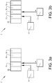
- Fig. 3a shows in a schematic view an example embodiment of the system where the first power source 4 is arranged for supplying power to at least one electric load 15 of the ADAS 2 and the second power source 5 is arranged for supplying electric power to said at least one electric load 15.
- the ADAS can comprise further electric loads 16 powered by the first power source and/or the second power source.
- Fig. 3b shows in a schematic view an example embodiment of the system where the first power source 4 is arranged for supplying power to a first electric load 15 of the ADAS and the second power source 5 is arranged for supplying power to a second load 17 of the ADAS 2.
- the first electric load 15 and the second electric load 17 are associated with a first function and a second function, respectively.
- the first function and the second function have at least partly overlapping characteristics, or the first function and the second function are two functions of the same type.
- the ADAS can comprise further electric loads 16 powered by the first power source and/or the second power source.
- the electric power system 3 has a first electric battery 18 which is arranged to be charged by the first power source 4.
- the first battery 18 is arranged for supplying electric power to the ADAS 2.
- the first battery 18 can also be used for supplying electric power to a starter motor 19 of the vehicle and/or any further load 20 not included in the ADAS.
- the electric power system 3 can also have a second electric battery 21 which is arranged to be charged by the second power source 5.
- the second battery 21 is arranged for supplying electric power to the ADAS 2.
- the second battery 21 can also be used for supplying electric power to any further load 22 not included in the ADAS.
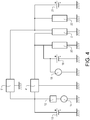
- Fig. 4 shows a circuit diagram of a variant of the electric power system.
- the first power source 4' and the second power source 5' are separated from each other.
- Fig. 5 shows a circuit diagram of a further variant of the electric power system.
- the system comprises a super capacitor module 23 with a super capacitor 24 and switches.
- the super capacitor 24 can be electrically connected to the first power supply line 8 to be charged by the first power source 4.
- the super capacitor 24 When the super capacitor 24 has been charged it can be disconnected from the first power supply line 8.
- the charged super capacitor 24 can then be electrically connected to the starter motor 19 for supplying electric power to the starter motor 19 if requested.
Landscapes
- Engineering & Computer Science (AREA)
- Power Engineering (AREA)
- Mechanical Engineering (AREA)
- Transportation (AREA)
- Life Sciences & Earth Sciences (AREA)
- Sustainable Development (AREA)
- Sustainable Energy (AREA)
- Chemical & Material Sciences (AREA)
- Combustion & Propulsion (AREA)
- General Engineering & Computer Science (AREA)
- Charge And Discharge Circuits For Batteries Or The Like (AREA)
Abstract
Description
- The invention relates to an electric power system for a vehicle having an advanced driver assistance system (ADAS), and to a vehicle having an advanced driver assistance system and such an electric power system.
- Modern vehicles often have advanced driver assistance systems for helping the driver in the driving process for safety and better driving. Such a system having functions involved during an autonomous driving mode, such as for example Active Safety Domain Master (ASDM) and Electric Power Assisted Steering (EPAS), has to be robust and be able to work at least during the time it takes to perform the requisite manoeuvres for reaching a safe state in case of an error in the system. Since the time to reach a safe state in the event of a worst case scenario is hard to predict, this in turn makes the work of dimensioning a battery supplying power to the system very difficult.
- An objective of the invention is to provide an electric power system for a vehicle having an advanced driver assistance system, which electric power system will enable an improved safety.
- The objective is achieved by an electric power system for a vehicle having an advanced driver assistance system (ADAS), wherein the electric power system comprises a first power source arranged for supplying electric power to the ADAS, and the electric power system comprises a second power source arranged for supplying electric power to the ADAS.
- The invention is based on the insight that by such a system, the dimensioning of the battery is less critical since the power supply is secured even if an error should occur in one of the power sources or corresponding circuit. For example, the first power source can be a DC-to-DC converter for converting a first voltage to a second lower voltage supplied to the ADAS, and the second power source can be another DC-to-DC converter for converting a first voltage to a second lower voltage supplied to the ADAS.
- Functions associated with the electric loads of the ADAS can be one or more of the following: Primary braking actuator, Secondary braking actuator, Primary steering actuator, Secondary steering actuator, Primary calculation unit, Secondary calculation unit, Primary front sensing unit (radar or visual) and Secondary front sensing unit (radar or visual). However, it should be clear to the skilled engineer of the field that the list is not exhaustive as there are further sensors to monitor surrounding (360 degrees) traffic and infrastructure as well as other actuators, such as belt pre-tensioner, accelerator, lighting, suspension, etc. that may be applicable to implement ADAS functionality.
- According to one embodiment of the system, the first power source is arranged for supplying power to at least one electric load of the ADAS and the second power source is arranged for supplying electric power to said at least one electric load. Hereby, the function associated with the electric load can be secured even if the first power source or the second power source for some reason could not supply power.
- For example, said at least one electric load can be an electric control unit controlling a steering actuator function of the ADAS or an electric control unit controlling a front sensing function of the ADAS.
- According to a further embodiment of the system, the first power source is arranged for supplying power to a first electric load of the ADAS and the second power source is arranged for supplying power to a second load of the ADAS. Hereby, at least one of a first function associated with the first electric load and a second function associated with the second electric load can be secured even if the first power source or the second power source for some reason could not supply power.
- For example, the first electric load can be an electric control unit controlling a primary braking actuator function of the ADAS and the second electric load can be a control unit controlling a secondary braking actuator function of the ADAS, or the first electric load can a primary calculation unit for providing actuation based on input from a primary sensor of the ADAS and the second electric load can be a secondary calculation unit for providing actuation based on input from a secondary sensor of the ADAS. In this context it may be understood that a calculation unit for providing actuation based on input from a sensor of the ADAS, may provide actuation for example as a data signal sent to other vehicular control units to or as a controlling voltage to a pump, motor, solenoid, etc.
- According to a further embodiment, the electric power system has an electric battery, wherein the electric battery is arranged to be charged by the first power source and for supplying electric power to the ADAS. Hereby, an energy storage capacity for the energy supply from the first power source is achieved. The battery can be used during peak loads and if the first power source fails.
- According to a further embodiment, the electric power system has an electric battery, the electric battery being arranged to be charged by the second power source and for supplying electric power to the ADAS. Hereby, an energy storage capacity for the energy supply from the second power source is achieved. The battery can be used during peak loads and if the second power source fails.
- According to a further embodiment, the electric power system has a super capacitor arranged to be charged by the first power source and for supplying electric power to a starter motor of the vehicle. Hereby, the starter motor can be powered during driving of a vehicle while not affecting the voltage stability of the remaining electric system.
- According to another aspect of the invention, a further objective is to provide a vehicle comprising an advanced driver assistance system and an electric power system.
- The advantages of the vehicle are substantially the same as the advantages already discussed hereinabove with reference to the different embodiments of the electric power system.
- Further advantages and advantageous features of the invention are disclosed in the following description and the claims.
- With reference to the appended drawings, below follows a more detailed description of embodiments of the invention cited as examples.
- In the drawings:
-
Fig. 1 shows a vehicle comprising an advanced driver assistance system and an electric power system, -
Fig. 2 shows a circuit diagram of the electric power system inFig. 1 , -
Fig. 3a shows a schematic view of a load of ADAS supplied by both a first power source and a second power source, -
Fig. 3b shows a schematic view of two loads of ADAS supplied by a first power source and a second power source, respectively, -
Fig. 4 shows a circuit diagram of a variant of the electric power system inFig. 2 , and -
Fig. 5 shows a circuit diagram of a further variant of the electric power system inFig. 2 . -
Fig. 1 shows avehicle 1 having an advanced driver assistance system (ADAS) 2 and anelectric power system 3. Theelectric power system 3 will be further described hereinbelow with reference toFigs. 2-5 . As schematically indicated inFig. 1 , theelectric power system 3 supplies electric power to the ADAS 2. -
Fig. 2 shows theelectric power system 3 for the vehicle inFig. 1 illustrated by a circuit diagram. As mentioned, the vehicle has an advanceddriver assistance system 2 powered by theelectric power system 3. Theelectric power system 3 comprising afirst power source 4 arranged for supplying electric power to the ADAS 2 and asecond power source 5 arranged for supplying electric power to the ADAS 2. In the example embodiment illustrated inFig. 2 , thefirst power source 4 is a DC-to-DC converter and the DC-to-DC converter is arranged for converting afirst voltage 6 to a second lower voltage 7 supplied to theADAS 2. Further, thesecond power source 5 is a DC-to-DC converter and the DC-to-DC converter is arranged for converting afirst voltage 6 to a second lower voltage 7 supplied to theADAS 2. Preferably, the first power source and the second power source provide the same voltage level. For example, the voltage can be converted from the firsthigher voltage 6 to the second lower voltage 7 being 12V. - The
first power source 4 and thesecond power source 5 are independent of each other for supplying power independently to the ADAS 2. Thefirst power source 4 is electrically connected to the ADAS 2 by a first power supply line 8 and thesecond power source 5 is electrically connected to the ADAS 2 by a second power supply line 9. - The ADAS 2 can comprise one or more functions and electric loads associated to the functions. The detailed architecture and components of ADAS, such as actuators, control units and sensors, are not further described hereinafter, since these should be known by the person skilled in the art.
- Thus, one or more ADAS-loads can be connected between the voltage level provided by the power sources and earth.
- By the expression independent power sources is meant that each
power source Fig. 2 , thefirst power source 4 has anoutput 10 providing a voltage of 12V on the first power supply line 8, and thesecond power source 5 has anotheroutput 11 providing a voltage of 12V on the second power supply line 9. Thepower sources power sources - Further, if the
first power source 4 is a DC-to-DC converter and thesecond power source 5 is a DC-to-DC converter, the converters can be powered by thesame power source 12 providing the firsthigher voltage 6, or the converters can be powered by two separate power sources each providing the first higher voltage. In the example embodiment illustrated inFig. 2 , the DC-to-DC converters are powered from an AC-to-DC converter 12 and from abattery 13 arranged to be charged by the AC-to-DC converter 12. The AC-to-DC converter is in turn powered by an electric (starter)generator 14 such as for example a BSG or ISG. The firsthigher voltage 6 that constitutes input to the DC-to-DC converters can be for example 400V or 48V. -
Fig. 3a shows in a schematic view an example embodiment of the system where thefirst power source 4 is arranged for supplying power to at least oneelectric load 15 of theADAS 2 and thesecond power source 5 is arranged for supplying electric power to said at least oneelectric load 15. In this way power supply redundancy can be achieved for theelectric load 15 and the function associated with theelectric load 15, since theelectric load 15 is electrically connected to both thefirst power source 4 and thesecond power source 5 by the first power supply line 8 and the second power supply line 9, respectively. Optionally, the ADAS can comprise furtherelectric loads 16 powered by the first power source and/or the second power source. -
Fig. 3b shows in a schematic view an example embodiment of the system where thefirst power source 4 is arranged for supplying power to a firstelectric load 15 of the ADAS and thesecond power source 5 is arranged for supplying power to asecond load 17 of theADAS 2. The firstelectric load 15 and the secondelectric load 17 are associated with a first function and a second function, respectively. The first function and the second function have at least partly overlapping characteristics, or the first function and the second function are two functions of the same type. In this way function redundancy can be achieved, since thefirst load 15 is electrically connected to thefirst power source 4 by the first power supply line 8 and the secondelectric load 17 is electrically connected to thesecond power source 5 by the second power supply line 9. Optionally, the ADAS can comprise furtherelectric loads 16 powered by the first power source and/or the second power source. - With further reference to
Fig. 2 , theelectric power system 3 has a firstelectric battery 18 which is arranged to be charged by thefirst power source 4. Thefirst battery 18 is arranged for supplying electric power to theADAS 2. Thefirst battery 18 can also be used for supplying electric power to astarter motor 19 of the vehicle and/or anyfurther load 20 not included in the ADAS. Theelectric power system 3 can also have a secondelectric battery 21 which is arranged to be charged by thesecond power source 5. Thesecond battery 21 is arranged for supplying electric power to theADAS 2. Thesecond battery 21 can also be used for supplying electric power to anyfurther load 22 not included in the ADAS. -
Fig. 4 shows a circuit diagram of a variant of the electric power system. In this example embodiment the first power source 4' and the second power source 5' are separated from each other. As it regards remaining components, reference is made to the description of the electric power system illustrated inFig. 2 , and same reference numerals will indicate same or similar components.
Fig. 5 shows a circuit diagram of a further variant of the electric power system. In this example embodiment the system comprises asuper capacitor module 23 with asuper capacitor 24 and switches. By the super capacity module, thesuper capacitor 24 can be electrically connected to the first power supply line 8 to be charged by thefirst power source 4. When thesuper capacitor 24 has been charged it can be disconnected from the first power supply line 8. The chargedsuper capacitor 24 can then be electrically connected to thestarter motor 19 for supplying electric power to thestarter motor 19 if requested. - It is to be understood that the present invention is not limited to the embodiments described above and illustrated in the drawings; rather, the skilled person will recognize that many changes and modifications may be made within the scope of the appended claims.
Claims (15)
- An electric power system (3) for a vehicle having an advanced driver assistance system (ADAS) (2), the electric power system comprising a first power source (4) arranged for supplying electric power to the ADAS, characterized in that the electric power system comprises a second power source (5) arranged for supplying electric power to the ADAS.
- An electric power system according to claim 1, characterized in that the first power source (4) is arranged for supplying power to at least one electric load (15) of the ADAS (2) and the second power source (5) is arranged for supplying electric power to said at least one electric load (15).
- An electric power system according to claim 2, characterized in that said at least one electric load (15) is an electric control unit controlling a steering actuator function of the ADAS.
- An electric power system according to claim 2, characterized in that said at least one electric load (15) is an electric control unit controlling a front sensing function of the ADAS.
- An electric power system according to claim 1, characterized in that the first power source (4) is arranged for supplying power to a first electric load (15) of the ADAS and the second power source (5) is arranged for supplying power to a second load (17) of the ADAS.
- An electric power system according to claim 5, characterized in that the first electric load (15) is an electric control unit controlling a primary braking actuator function of the ADAS and the second electric load (17) is a control unit controlling a secondary braking actuator function of the ADAS.
- An electric power system according to claim 5, characterized in that the first electric load (15) is a primary calculation unit for providing actuation based on input from a primary sensor of the ADAS and the second electric load (17) is a secondary calculation unit for providing actuation based on input from a secondary sensor of the ADAS.
- An electric power system according to any of claims 1-7, characterized in that the first power source (4) is a DC-to-DC converter.
- An electric power system according to claim 8, characterized in that the DC-to-DC converter (4) is arranged for converting a first voltage (6) to a second lower voltage (7) supplied to the ADAS (2).
- An electric power system according to any preceding claim, characterized in that the second power source (5) is a DC-to-DC converter.
- An electric power system according to claim 10, characterized in that the DC-to-DC converter (5) is arranged for converting a first voltage (6) to a second lower voltage (7) supplied to the ADAS (2).
- An electric power system according to any preceding claim, characterized in that the electric power system (3) has an electric battery (18), the electric battery being arranged to be charged by the first power source (4) and for supplying electric power to the ADAS (2).
- An electric power system according to any preceding claim, characterized in that the electric power system has an electric battery (21), the electric battery being arranged to be charged by the second power source (5) and for supplying electric power to the ADAS (2).
- An electric power system according to any preceding claim, characterized in that the electric power system (3) has a super capacitor (24) arranged to be charged by the first power source (4) and for supplying electric power to a starter motor (19) of the vehicle.
- A vehicle (1) having an advanced driver assistance system (ADAS) (2) and an electric power system (3) according to any of claims 1-14.
Priority Applications (4)
| Application Number | Priority Date | Filing Date | Title |
|---|---|---|---|
| EP18200712.0A EP3640074B1 (en) | 2018-10-16 | 2018-10-16 | An electric power system |
| CN201980066184.2A CN112805188B (en) | 2018-10-16 | 2019-10-15 | Power supply system |
| PCT/CN2019/111155 WO2020078343A1 (en) | 2018-10-16 | 2019-10-15 | An electric power system |
| US17/203,176 US11981211B2 (en) | 2018-10-16 | 2021-03-16 | Electric power system |
Applications Claiming Priority (1)
| Application Number | Priority Date | Filing Date | Title |
|---|---|---|---|
| EP18200712.0A EP3640074B1 (en) | 2018-10-16 | 2018-10-16 | An electric power system |
Publications (2)
| Publication Number | Publication Date |
|---|---|
| EP3640074A1 true EP3640074A1 (en) | 2020-04-22 |
| EP3640074B1 EP3640074B1 (en) | 2022-12-21 |
Family
ID=64051308
Family Applications (1)
| Application Number | Title | Priority Date | Filing Date |
|---|---|---|---|
| EP18200712.0A Active EP3640074B1 (en) | 2018-10-16 | 2018-10-16 | An electric power system |
Country Status (4)
| Country | Link |
|---|---|
| US (1) | US11981211B2 (en) |
| EP (1) | EP3640074B1 (en) |
| CN (1) | CN112805188B (en) |
| WO (1) | WO2020078343A1 (en) |
Cited By (1)
| Publication number | Priority date | Publication date | Assignee | Title |
|---|---|---|---|---|
| SE2150567A1 (en) * | 2021-05-04 | 2022-11-05 | Scania Cv Ab | A method and a control arrangement for assisting a vehicle |
Families Citing this family (4)
| Publication number | Priority date | Publication date | Assignee | Title |
|---|---|---|---|---|
| WO2022067337A1 (en) * | 2020-09-24 | 2022-03-31 | Polestar Automotive Usa Inc. | Redundant power supply |
| CN116868470A (en) * | 2020-11-12 | 2023-10-10 | 博乐斯达性能有限公司 | Flexible high voltage system |
| US20240291265A1 (en) * | 2023-02-24 | 2024-08-29 | Kold-Ban International, Ltd. | Protecting circuit for battery during engine starting events |
| DE102023125428B4 (en) | 2023-09-20 | 2025-06-12 | Dr. Ing. H.C. F. Porsche Aktiengesellschaft | Electric vehicle and method for operating the same |
Citations (3)
| Publication number | Priority date | Publication date | Assignee | Title |
|---|---|---|---|---|
| US20060145536A1 (en) * | 2003-02-10 | 2006-07-06 | Siemens Aktiengesellschaft | Device for supplying power to a two-voltage vehicle electric system |
| CN106058998A (en) * | 2016-04-18 | 2016-10-26 | 洛阳尹太科智能科技有限公司 | Diesel locomotive electrical system and a power supply method thereof |
| EP3254883A1 (en) * | 2016-06-07 | 2017-12-13 | Toyota Jidosha Kabushiki Kaisha | Power source system |
Family Cites Families (12)
| Publication number | Priority date | Publication date | Assignee | Title |
|---|---|---|---|---|
| CN2506483Y (en) * | 2001-10-09 | 2002-08-21 | 北京中高创业新能源科技发展有限责任公司 | Composite power source for electric driven vehicle |
| EP1555185A1 (en) * | 2004-01-15 | 2005-07-20 | Magnetek S.p.A. | Electrically driven rail vehicle with an emergency power generator and method of powering said vehicle. |
| DE102006010713B4 (en) * | 2006-03-08 | 2010-04-01 | Audi Ag | Vehicle electrical system for a vehicle and method for supplying energy to a safety-relevant consumer of a vehicle electrical system |
| DE102009012734A1 (en) * | 2009-03-11 | 2010-09-16 | GM Global Technology Operations, Inc., Detroit | Vehicle comprises vehicle engine, alternator, direct current network and alternating current network that are supplied by vehicle battery which is electrically connected with alternator |
| US9896048B2 (en) * | 2012-10-02 | 2018-02-20 | Technoboost | Power supply unit for supplying power to an on-board electrical network of a vehicle |
| CN103101428A (en) * | 2013-03-01 | 2013-05-15 | 中国第一汽车股份有限公司 | Hybrid electric vehicle using super-capacitor accessory power system |
| CN103612569B (en) * | 2013-06-08 | 2016-06-15 | 苏州市莱赛电车技术有限公司 | A kind of electric vehicle power-supply system |
| JP6540565B2 (en) * | 2016-03-16 | 2019-07-10 | 株式会社オートネットワーク技術研究所 | Power supply system for vehicle, drive system for vehicle |
| JP6750316B2 (en) * | 2016-06-02 | 2020-09-02 | 日立化成株式会社 | Vehicle power supply system and automobile |
| EP3276787B1 (en) * | 2016-07-29 | 2019-01-02 | Ford Global Technologies, LLC | On-board electrical system for motor vehicles comprising a converter and a high-load consumer |
| CN106541910A (en) * | 2016-12-16 | 2017-03-29 | 深圳安狗数据技术有限公司 | A kind of ADAS equipment of automobile and its method of supplying power to |
| US10865759B2 (en) * | 2018-08-24 | 2020-12-15 | A Tech Aerospace, Inc. | Battery enhancer for a vehicle |
-
2018
- 2018-10-16 EP EP18200712.0A patent/EP3640074B1/en active Active
-
2019
- 2019-10-15 WO PCT/CN2019/111155 patent/WO2020078343A1/en not_active Ceased
- 2019-10-15 CN CN201980066184.2A patent/CN112805188B/en active Active
-
2021
- 2021-03-16 US US17/203,176 patent/US11981211B2/en active Active
Patent Citations (3)
| Publication number | Priority date | Publication date | Assignee | Title |
|---|---|---|---|---|
| US20060145536A1 (en) * | 2003-02-10 | 2006-07-06 | Siemens Aktiengesellschaft | Device for supplying power to a two-voltage vehicle electric system |
| CN106058998A (en) * | 2016-04-18 | 2016-10-26 | 洛阳尹太科智能科技有限公司 | Diesel locomotive electrical system and a power supply method thereof |
| EP3254883A1 (en) * | 2016-06-07 | 2017-12-13 | Toyota Jidosha Kabushiki Kaisha | Power source system |
Cited By (2)
| Publication number | Priority date | Publication date | Assignee | Title |
|---|---|---|---|---|
| SE2150567A1 (en) * | 2021-05-04 | 2022-11-05 | Scania Cv Ab | A method and a control arrangement for assisting a vehicle |
| SE545591C2 (en) * | 2021-05-04 | 2023-11-07 | Scania Cv Ab | A method and a control arrangement for assisting a vehicle |
Also Published As
| Publication number | Publication date |
|---|---|
| CN112805188A (en) | 2021-05-14 |
| CN112805188B (en) | 2023-04-04 |
| US20210206275A1 (en) | 2021-07-08 |
| US11981211B2 (en) | 2024-05-14 |
| EP3640074B1 (en) | 2022-12-21 |
| WO2020078343A1 (en) | 2020-04-23 |
Similar Documents
| Publication | Publication Date | Title |
|---|---|---|
| EP3640074B1 (en) | An electric power system | |
| CN110875617B (en) | Power supply system for vehicle | |
| EP3530513B1 (en) | Vehicular electric power supply system | |
| CN106255622B (en) | Device for basic onboard power system to be connect with especially security-related subnetting | |
| KR20200026688A (en) | Electric power source system for vehicle | |
| CN107207000A (en) | Method from least one load supplying to onboard power system and onboard power system for | |
| JP7453897B2 (en) | Vehicle power supply device and control method for vehicle power supply device | |
| CN110893822A (en) | Vehicle-mounted power grid for motor vehicle | |
| CN108780997A (en) | Vehicle power supply system, vehicle drive system | |
| US12077112B2 (en) | Vehicle electrical system and power module therefor | |
| WO2021255985A1 (en) | Electronic control device and vehicle control method | |
| JP2016103935A (en) | Power supply system for vehicle and dc-dc converter | |
| WO2017051736A1 (en) | Onboard power-source device | |
| JP7551581B2 (en) | Vehicle Power System | |
| DE102022106978A1 (en) | Converter device and method for operating a converter device for electrical energy conversion for an on-board electrical system of a vehicle | |
| US20240066992A1 (en) | Charging system and charger therefor | |
| US20210146905A1 (en) | Emergency energy store for a vehicle | |
| JP2007131134A (en) | Vehicle power supply | |
| CN109155532A (en) | For providing the method and apparatus of electric energy to device | |
| CN113306410A (en) | Redundant vehicle electrical system and motor vehicle | |
| US12603518B2 (en) | Redundant power supply system | |
| EP4707092A1 (en) | Improved redundant power supply for electro-mechanic brake systems in a vehicle, preferably in a commercial vehicle | |
| KR20160097572A (en) | Emergency braking system | |
| CN220262570U (en) | Emergency power-off device of power supply and electric automobile | |
| US20260142253A1 (en) | On-board electrical system for a motor vehicle and motor vehicle |
Legal Events
| Date | Code | Title | Description |
|---|---|---|---|
| PUAI | Public reference made under article 153(3) epc to a published international application that has entered the european phase |
Free format text: ORIGINAL CODE: 0009012 |
|
| STAA | Information on the status of an ep patent application or granted ep patent |
Free format text: STATUS: REQUEST FOR EXAMINATION WAS MADE |
|
| 17P | Request for examination filed |
Effective date: 20181016 |
|
| AK | Designated contracting states |
Kind code of ref document: A1 Designated state(s): AL AT BE BG CH CY CZ DE DK EE ES FI FR GB GR HR HU IE IS IT LI LT LU LV MC MK MT NL NO PL PT RO RS SE SI SK SM TR |
|
| AX | Request for extension of the european patent |
Extension state: BA ME |
|
| GRAP | Despatch of communication of intention to grant a patent |
Free format text: ORIGINAL CODE: EPIDOSNIGR1 |
|
| STAA | Information on the status of an ep patent application or granted ep patent |
Free format text: STATUS: GRANT OF PATENT IS INTENDED |
|
| INTG | Intention to grant announced |
Effective date: 20220729 |
|
| GRAS | Grant fee paid |
Free format text: ORIGINAL CODE: EPIDOSNIGR3 |
|
| GRAA | (expected) grant |
Free format text: ORIGINAL CODE: 0009210 |
|
| STAA | Information on the status of an ep patent application or granted ep patent |
Free format text: STATUS: THE PATENT HAS BEEN GRANTED |
|
| AK | Designated contracting states |
Kind code of ref document: B1 Designated state(s): AL AT BE BG CH CY CZ DE DK EE ES FI FR GB GR HR HU IE IS IT LI LT LU LV MC MK MT NL NO PL PT RO RS SE SI SK SM TR |
|
| REG | Reference to a national code |
Ref country code: GB Ref legal event code: FG4D |
|
| REG | Reference to a national code |
Ref country code: CH Ref legal event code: EP |
|
| REG | Reference to a national code |
Ref country code: DE Ref legal event code: R096 Ref document number: 602018044439 Country of ref document: DE |
|
| REG | Reference to a national code |
Ref country code: AT Ref legal event code: REF Ref document number: 1538859 Country of ref document: AT Kind code of ref document: T Effective date: 20230115 |
|
| REG | Reference to a national code |
Ref country code: IE Ref legal event code: FG4D |
|
| REG | Reference to a national code |
Ref country code: LT Ref legal event code: MG9D |
|
| REG | Reference to a national code |
Ref country code: NL Ref legal event code: MP Effective date: 20221221 |
|
| PG25 | Lapsed in a contracting state [announced via postgrant information from national office to epo] |
Ref country code: SE Free format text: LAPSE BECAUSE OF FAILURE TO SUBMIT A TRANSLATION OF THE DESCRIPTION OR TO PAY THE FEE WITHIN THE PRESCRIBED TIME-LIMIT Effective date: 20221221 Ref country code: NO Free format text: LAPSE BECAUSE OF FAILURE TO SUBMIT A TRANSLATION OF THE DESCRIPTION OR TO PAY THE FEE WITHIN THE PRESCRIBED TIME-LIMIT Effective date: 20230321 Ref country code: LT Free format text: LAPSE BECAUSE OF FAILURE TO SUBMIT A TRANSLATION OF THE DESCRIPTION OR TO PAY THE FEE WITHIN THE PRESCRIBED TIME-LIMIT Effective date: 20221221 Ref country code: FI Free format text: LAPSE BECAUSE OF FAILURE TO SUBMIT A TRANSLATION OF THE DESCRIPTION OR TO PAY THE FEE WITHIN THE PRESCRIBED TIME-LIMIT Effective date: 20221221 |
|
| REG | Reference to a national code |
Ref country code: AT Ref legal event code: MK05 Ref document number: 1538859 Country of ref document: AT Kind code of ref document: T Effective date: 20221221 |
|
| PG25 | Lapsed in a contracting state [announced via postgrant information from national office to epo] |
Ref country code: RS Free format text: LAPSE BECAUSE OF FAILURE TO SUBMIT A TRANSLATION OF THE DESCRIPTION OR TO PAY THE FEE WITHIN THE PRESCRIBED TIME-LIMIT Effective date: 20221221 Ref country code: LV Free format text: LAPSE BECAUSE OF FAILURE TO SUBMIT A TRANSLATION OF THE DESCRIPTION OR TO PAY THE FEE WITHIN THE PRESCRIBED TIME-LIMIT Effective date: 20221221 Ref country code: HR Free format text: LAPSE BECAUSE OF FAILURE TO SUBMIT A TRANSLATION OF THE DESCRIPTION OR TO PAY THE FEE WITHIN THE PRESCRIBED TIME-LIMIT Effective date: 20221221 |
|
| PG25 | Lapsed in a contracting state [announced via postgrant information from national office to epo] |
Ref country code: NL Free format text: LAPSE BECAUSE OF FAILURE TO SUBMIT A TRANSLATION OF THE DESCRIPTION OR TO PAY THE FEE WITHIN THE PRESCRIBED TIME-LIMIT Effective date: 20221221 |
|
| PG25 | Lapsed in a contracting state [announced via postgrant information from national office to epo] |
Ref country code: SM Free format text: LAPSE BECAUSE OF FAILURE TO SUBMIT A TRANSLATION OF THE DESCRIPTION OR TO PAY THE FEE WITHIN THE PRESCRIBED TIME-LIMIT Effective date: 20221221 Ref country code: RO Free format text: LAPSE BECAUSE OF FAILURE TO SUBMIT A TRANSLATION OF THE DESCRIPTION OR TO PAY THE FEE WITHIN THE PRESCRIBED TIME-LIMIT Effective date: 20221221 Ref country code: PT Free format text: LAPSE BECAUSE OF FAILURE TO SUBMIT A TRANSLATION OF THE DESCRIPTION OR TO PAY THE FEE WITHIN THE PRESCRIBED TIME-LIMIT Effective date: 20230421 Ref country code: ES Free format text: LAPSE BECAUSE OF FAILURE TO SUBMIT A TRANSLATION OF THE DESCRIPTION OR TO PAY THE FEE WITHIN THE PRESCRIBED TIME-LIMIT Effective date: 20221221 Ref country code: EE Free format text: LAPSE BECAUSE OF FAILURE TO SUBMIT A TRANSLATION OF THE DESCRIPTION OR TO PAY THE FEE WITHIN THE PRESCRIBED TIME-LIMIT Effective date: 20221221 Ref country code: CZ Free format text: LAPSE BECAUSE OF FAILURE TO SUBMIT A TRANSLATION OF THE DESCRIPTION OR TO PAY THE FEE WITHIN THE PRESCRIBED TIME-LIMIT Effective date: 20221221 Ref country code: AT Free format text: LAPSE BECAUSE OF FAILURE TO SUBMIT A TRANSLATION OF THE DESCRIPTION OR TO PAY THE FEE WITHIN THE PRESCRIBED TIME-LIMIT Effective date: 20221221 |
|
| PG25 | Lapsed in a contracting state [announced via postgrant information from national office to epo] |
Ref country code: SK Free format text: LAPSE BECAUSE OF FAILURE TO SUBMIT A TRANSLATION OF THE DESCRIPTION OR TO PAY THE FEE WITHIN THE PRESCRIBED TIME-LIMIT Effective date: 20221221 Ref country code: PL Free format text: LAPSE BECAUSE OF FAILURE TO SUBMIT A TRANSLATION OF THE DESCRIPTION OR TO PAY THE FEE WITHIN THE PRESCRIBED TIME-LIMIT Effective date: 20221221 Ref country code: IS Free format text: LAPSE BECAUSE OF FAILURE TO SUBMIT A TRANSLATION OF THE DESCRIPTION OR TO PAY THE FEE WITHIN THE PRESCRIBED TIME-LIMIT Effective date: 20230421 Ref country code: AL Free format text: LAPSE BECAUSE OF FAILURE TO SUBMIT A TRANSLATION OF THE DESCRIPTION OR TO PAY THE FEE WITHIN THE PRESCRIBED TIME-LIMIT Effective date: 20221221 |
|
| REG | Reference to a national code |
Ref country code: DE Ref legal event code: R097 Ref document number: 602018044439 Country of ref document: DE |
|
| PLBE | No opposition filed within time limit |
Free format text: ORIGINAL CODE: 0009261 |
|
| STAA | Information on the status of an ep patent application or granted ep patent |
Free format text: STATUS: NO OPPOSITION FILED WITHIN TIME LIMIT |
|
| PG25 | Lapsed in a contracting state [announced via postgrant information from national office to epo] |
Ref country code: DK Free format text: LAPSE BECAUSE OF FAILURE TO SUBMIT A TRANSLATION OF THE DESCRIPTION OR TO PAY THE FEE WITHIN THE PRESCRIBED TIME-LIMIT Effective date: 20221221 |
|
| 26N | No opposition filed |
Effective date: 20230922 |
|
| PG25 | Lapsed in a contracting state [announced via postgrant information from national office to epo] |
Ref country code: SI Free format text: LAPSE BECAUSE OF FAILURE TO SUBMIT A TRANSLATION OF THE DESCRIPTION OR TO PAY THE FEE WITHIN THE PRESCRIBED TIME-LIMIT Effective date: 20221221 |
|
| PG25 | Lapsed in a contracting state [announced via postgrant information from national office to epo] |
Ref country code: IT Free format text: LAPSE BECAUSE OF FAILURE TO SUBMIT A TRANSLATION OF THE DESCRIPTION OR TO PAY THE FEE WITHIN THE PRESCRIBED TIME-LIMIT Effective date: 20221221 Ref country code: MC Free format text: LAPSE BECAUSE OF FAILURE TO SUBMIT A TRANSLATION OF THE DESCRIPTION OR TO PAY THE FEE WITHIN THE PRESCRIBED TIME-LIMIT Effective date: 20221221 |
|
| REG | Reference to a national code |
Ref country code: CH Ref legal event code: PL |
|
| REG | Reference to a national code |
Ref country code: BE Ref legal event code: MM Effective date: 20231031 |
|
| PG25 | Lapsed in a contracting state [announced via postgrant information from national office to epo] |
Ref country code: LU Free format text: LAPSE BECAUSE OF NON-PAYMENT OF DUE FEES Effective date: 20231016 |
|
| PG25 | Lapsed in a contracting state [announced via postgrant information from national office to epo] |
Ref country code: LU Free format text: LAPSE BECAUSE OF NON-PAYMENT OF DUE FEES Effective date: 20231016 |
|
| PG25 | Lapsed in a contracting state [announced via postgrant information from national office to epo] |
Ref country code: CH Free format text: LAPSE BECAUSE OF NON-PAYMENT OF DUE FEES Effective date: 20231031 |
|
| PG25 | Lapsed in a contracting state [announced via postgrant information from national office to epo] |
Ref country code: CH Free format text: LAPSE BECAUSE OF NON-PAYMENT OF DUE FEES Effective date: 20231031 |
|
| PG25 | Lapsed in a contracting state [announced via postgrant information from national office to epo] |
Ref country code: BE Free format text: LAPSE BECAUSE OF NON-PAYMENT OF DUE FEES Effective date: 20231031 |
|
| PG25 | Lapsed in a contracting state [announced via postgrant information from national office to epo] |
Ref country code: IE Free format text: LAPSE BECAUSE OF NON-PAYMENT OF DUE FEES Effective date: 20231016 |
|
| PG25 | Lapsed in a contracting state [announced via postgrant information from national office to epo] |
Ref country code: IE Free format text: LAPSE BECAUSE OF NON-PAYMENT OF DUE FEES Effective date: 20231016 |
|
| PG25 | Lapsed in a contracting state [announced via postgrant information from national office to epo] |
Ref country code: BG Free format text: LAPSE BECAUSE OF FAILURE TO SUBMIT A TRANSLATION OF THE DESCRIPTION OR TO PAY THE FEE WITHIN THE PRESCRIBED TIME-LIMIT Effective date: 20221221 |
|
| PG25 | Lapsed in a contracting state [announced via postgrant information from national office to epo] |
Ref country code: BG Free format text: LAPSE BECAUSE OF FAILURE TO SUBMIT A TRANSLATION OF THE DESCRIPTION OR TO PAY THE FEE WITHIN THE PRESCRIBED TIME-LIMIT Effective date: 20221221 |
|
| PG25 | Lapsed in a contracting state [announced via postgrant information from national office to epo] |
Ref country code: CY Free format text: LAPSE BECAUSE OF FAILURE TO SUBMIT A TRANSLATION OF THE DESCRIPTION OR TO PAY THE FEE WITHIN THE PRESCRIBED TIME-LIMIT; INVALID AB INITIO Effective date: 20181016 |
|
| PG25 | Lapsed in a contracting state [announced via postgrant information from national office to epo] |
Ref country code: HU Free format text: LAPSE BECAUSE OF FAILURE TO SUBMIT A TRANSLATION OF THE DESCRIPTION OR TO PAY THE FEE WITHIN THE PRESCRIBED TIME-LIMIT; INVALID AB INITIO Effective date: 20181016 |
|
| PG25 | Lapsed in a contracting state [announced via postgrant information from national office to epo] |
Ref country code: GR Free format text: LAPSE BECAUSE OF FAILURE TO SUBMIT A TRANSLATION OF THE DESCRIPTION OR TO PAY THE FEE WITHIN THE PRESCRIBED TIME-LIMIT; INVALID AB INITIO Effective date: 20181016 |
|
| PGFP | Annual fee paid to national office [announced via postgrant information from national office to epo] |
Ref country code: GB Payment date: 20250825 Year of fee payment: 8 |
|
| PGFP | Annual fee paid to national office [announced via postgrant information from national office to epo] |
Ref country code: FR Payment date: 20250820 Year of fee payment: 8 |
|
| PG25 | Lapsed in a contracting state [announced via postgrant information from national office to epo] |
Ref country code: TR Free format text: LAPSE BECAUSE OF FAILURE TO SUBMIT A TRANSLATION OF THE DESCRIPTION OR TO PAY THE FEE WITHIN THE PRESCRIBED TIME-LIMIT Effective date: 20221221 |
|
| PGFP | Annual fee paid to national office [announced via postgrant information from national office to epo] |
Ref country code: DE Payment date: 20251020 Year of fee payment: 8 |