EP3640045A1 - Metal-resin composite member for tire, and tire - Google Patents
Metal-resin composite member for tire, and tire Download PDFInfo
- Publication number
- EP3640045A1 EP3640045A1 EP18816962.7A EP18816962A EP3640045A1 EP 3640045 A1 EP3640045 A1 EP 3640045A1 EP 18816962 A EP18816962 A EP 18816962A EP 3640045 A1 EP3640045 A1 EP 3640045A1
- Authority
- EP
- European Patent Office
- Prior art keywords
- resin
- tire
- metal
- composite member
- cord
- Prior art date
- Legal status (The legal status is an assumption and is not a legal conclusion. Google has not performed a legal analysis and makes no representation as to the accuracy of the status listed.)
- Withdrawn
Links
- 239000000805 composite resin Substances 0.000 title claims abstract description 55
- 229920005989 resin Polymers 0.000 claims abstract description 192
- 239000011347 resin Substances 0.000 claims abstract description 192
- 229920000728 polyester Polymers 0.000 claims abstract description 77
- 229920002725 thermoplastic elastomer Polymers 0.000 claims abstract description 52
- 239000000203 mixture Substances 0.000 claims abstract description 50
- 229920006127 amorphous resin Polymers 0.000 claims abstract description 45
- 229910052751 metal Inorganic materials 0.000 claims abstract description 42
- 239000002184 metal Substances 0.000 claims abstract description 42
- 230000009477 glass transition Effects 0.000 claims abstract description 7
- 239000000463 material Substances 0.000 claims description 58
- 229920005992 thermoplastic resin Polymers 0.000 claims description 50
- 238000002844 melting Methods 0.000 claims description 39
- 230000008018 melting Effects 0.000 claims description 38
- 238000004804 winding Methods 0.000 claims description 5
- 229920000515 polycarbonate Polymers 0.000 claims description 4
- 239000004417 polycarbonate Substances 0.000 claims description 4
- 239000010410 layer Substances 0.000 description 70
- -1 age resistors Substances 0.000 description 56
- 230000003014 reinforcing effect Effects 0.000 description 46
- LYCAIKOWRPUZTN-UHFFFAOYSA-N Ethylene glycol Chemical compound OCCO LYCAIKOWRPUZTN-UHFFFAOYSA-N 0.000 description 25
- 229920001971 elastomer Polymers 0.000 description 25
- 239000005060 rubber Substances 0.000 description 23
- 239000011324 bead Substances 0.000 description 20
- 230000000052 comparative effect Effects 0.000 description 14
- 229920001707 polybutylene terephthalate Polymers 0.000 description 14
- 239000012790 adhesive layer Substances 0.000 description 13
- 238000000034 method Methods 0.000 description 12
- 238000010438 heat treatment Methods 0.000 description 11
- WGCNASOHLSPBMP-UHFFFAOYSA-N hydroxyacetaldehyde Natural products OCC=O WGCNASOHLSPBMP-UHFFFAOYSA-N 0.000 description 11
- 239000011248 coating agent Substances 0.000 description 9
- 238000000576 coating method Methods 0.000 description 9
- 229920000642 polymer Polymers 0.000 description 9
- 239000000853 adhesive Substances 0.000 description 8
- 230000001070 adhesive effect Effects 0.000 description 8
- 239000007767 bonding agent Substances 0.000 description 8
- 238000000113 differential scanning calorimetry Methods 0.000 description 8
- 238000007789 sealing Methods 0.000 description 8
- 230000002349 favourable effect Effects 0.000 description 7
- 101000763003 Homo sapiens Two pore channel protein 1 Proteins 0.000 description 6
- 241000428199 Mustelinae Species 0.000 description 6
- 102100026736 Two pore channel protein 1 Human genes 0.000 description 6
- 239000003570 air Substances 0.000 description 6
- 238000000465 moulding Methods 0.000 description 6
- 238000004073 vulcanization Methods 0.000 description 6
- 230000015572 biosynthetic process Effects 0.000 description 5
- 238000005259 measurement Methods 0.000 description 5
- VTYYLEPIZMXCLO-UHFFFAOYSA-L Calcium carbonate Chemical compound [Ca+2].[O-]C([O-])=O VTYYLEPIZMXCLO-UHFFFAOYSA-L 0.000 description 4
- 101000679525 Homo sapiens Two pore channel protein 2 Proteins 0.000 description 4
- OFOBLEOULBTSOW-UHFFFAOYSA-N Malonic acid Chemical compound OC(=O)CC(O)=O OFOBLEOULBTSOW-UHFFFAOYSA-N 0.000 description 4
- VYPSYNLAJGMNEJ-UHFFFAOYSA-N Silicium dioxide Chemical compound O=[Si]=O VYPSYNLAJGMNEJ-UHFFFAOYSA-N 0.000 description 4
- 229910000831 Steel Inorganic materials 0.000 description 4
- 102100022609 Two pore channel protein 2 Human genes 0.000 description 4
- 125000003118 aryl group Chemical group 0.000 description 4
- 230000000694 effects Effects 0.000 description 4
- 229920000139 polyethylene terephthalate Polymers 0.000 description 4
- 239000005020 polyethylene terephthalate Substances 0.000 description 4
- 230000008569 process Effects 0.000 description 4
- 239000010959 steel Substances 0.000 description 4
- 125000001931 aliphatic group Chemical group 0.000 description 3
- 229920003232 aliphatic polyester Polymers 0.000 description 3
- 238000005422 blasting Methods 0.000 description 3
- 229920001577 copolymer Polymers 0.000 description 3
- 229920006351 engineering plastic Polymers 0.000 description 3
- 238000011156 evaluation Methods 0.000 description 3
- 239000000835 fiber Substances 0.000 description 3
- 125000000524 functional group Chemical group 0.000 description 3
- 238000004519 manufacturing process Methods 0.000 description 3
- 238000002156 mixing Methods 0.000 description 3
- 229920000570 polyether Polymers 0.000 description 3
- 239000011112 polyethylene naphthalate Substances 0.000 description 3
- 229920001451 polypropylene glycol Polymers 0.000 description 3
- 239000004814 polyurethane Substances 0.000 description 3
- 238000007788 roughening Methods 0.000 description 3
- 238000012546 transfer Methods 0.000 description 3
- PUPZLCDOIYMWBV-UHFFFAOYSA-N (+/-)-1,3-Butanediol Chemical compound CC(O)CCO PUPZLCDOIYMWBV-UHFFFAOYSA-N 0.000 description 2
- VGGSQFUCUMXWEO-UHFFFAOYSA-N Ethene Chemical compound C=C VGGSQFUCUMXWEO-UHFFFAOYSA-N 0.000 description 2
- 239000005977 Ethylene Substances 0.000 description 2
- IAYPIBMASNFSPL-UHFFFAOYSA-N Ethylene oxide Chemical compound C1CO1 IAYPIBMASNFSPL-UHFFFAOYSA-N 0.000 description 2
- 238000005481 NMR spectroscopy Methods 0.000 description 2
- 229920003171 Poly (ethylene oxide) Polymers 0.000 description 2
- 239000004721 Polyphenylene oxide Substances 0.000 description 2
- 239000004793 Polystyrene Substances 0.000 description 2
- PPBRXRYQALVLMV-UHFFFAOYSA-N Styrene Chemical compound C=CC1=CC=CC=C1 PPBRXRYQALVLMV-UHFFFAOYSA-N 0.000 description 2
- KKEYFWRCBNTPAC-UHFFFAOYSA-N Terephthalic acid Chemical compound OC(=O)C1=CC=C(C(O)=O)C=C1 KKEYFWRCBNTPAC-UHFFFAOYSA-N 0.000 description 2
- WYURNTSHIVDZCO-UHFFFAOYSA-N Tetrahydrofuran Chemical compound C1CCOC1 WYURNTSHIVDZCO-UHFFFAOYSA-N 0.000 description 2
- 150000001336 alkenes Chemical class 0.000 description 2
- WERYXYBDKMZEQL-UHFFFAOYSA-N butane-1,4-diol Chemical compound OCCCCO WERYXYBDKMZEQL-UHFFFAOYSA-N 0.000 description 2
- 229910000019 calcium carbonate Inorganic materials 0.000 description 2
- 239000003795 chemical substances by application Substances 0.000 description 2
- 239000004927 clay Substances 0.000 description 2
- 229910052570 clay Inorganic materials 0.000 description 2
- 150000001875 compounds Chemical class 0.000 description 2
- 238000001816 cooling Methods 0.000 description 2
- WOZVHXUHUFLZGK-UHFFFAOYSA-N dimethyl terephthalate Chemical compound COC(=O)C1=CC=C(C(=O)OC)C=C1 WOZVHXUHUFLZGK-UHFFFAOYSA-N 0.000 description 2
- 150000002009 diols Chemical class 0.000 description 2
- 239000000806 elastomer Substances 0.000 description 2
- 239000000945 filler Substances 0.000 description 2
- 230000001788 irregular Effects 0.000 description 2
- QQVIHTHCMHWDBS-UHFFFAOYSA-N isophthalic acid Chemical compound OC(=O)C1=CC=CC(C(O)=O)=C1 QQVIHTHCMHWDBS-UHFFFAOYSA-N 0.000 description 2
- 238000012986 modification Methods 0.000 description 2
- 230000004048 modification Effects 0.000 description 2
- 239000003921 oil Substances 0.000 description 2
- JRZJOMJEPLMPRA-UHFFFAOYSA-N olefin Natural products CCCCCCCC=C JRZJOMJEPLMPRA-UHFFFAOYSA-N 0.000 description 2
- XNGIFLGASWRNHJ-UHFFFAOYSA-N phthalic acid Chemical compound OC(=O)C1=CC=CC=C1C(O)=O XNGIFLGASWRNHJ-UHFFFAOYSA-N 0.000 description 2
- 239000004014 plasticizer Substances 0.000 description 2
- 229920003207 poly(ethylene-2,6-naphthalate) Polymers 0.000 description 2
- 229920001610 polycaprolactone Polymers 0.000 description 2
- 229920001225 polyester resin Polymers 0.000 description 2
- 239000004645 polyester resin Substances 0.000 description 2
- 229920000921 polyethylene adipate Polymers 0.000 description 2
- 229920002223 polystyrene Polymers 0.000 description 2
- 229920002635 polyurethane Polymers 0.000 description 2
- YPFDHNVEDLHUCE-UHFFFAOYSA-N propane-1,3-diol Chemical compound OCCCO YPFDHNVEDLHUCE-UHFFFAOYSA-N 0.000 description 2
- 239000000377 silicon dioxide Substances 0.000 description 2
- 238000010408 sweeping Methods 0.000 description 2
- DNTHXHASNDRODE-UHFFFAOYSA-N 2-[4-[1-[4-(2-hydroxyethoxy)phenyl]cyclohexyl]phenoxy]ethanol Chemical compound C1=CC(OCCO)=CC=C1C1(C=2C=CC(OCCO)=CC=2)CCCCC1 DNTHXHASNDRODE-UHFFFAOYSA-N 0.000 description 1
- KXGFMDJXCMQABM-UHFFFAOYSA-N 2-methoxy-6-methylphenol Chemical compound [CH]OC1=CC=CC([CH])=C1O KXGFMDJXCMQABM-UHFFFAOYSA-N 0.000 description 1
- XCSGHNKDXGYELG-UHFFFAOYSA-N 2-phenoxyethoxybenzene Chemical compound C=1C=CC=CC=1OCCOC1=CC=CC=C1 XCSGHNKDXGYELG-UHFFFAOYSA-N 0.000 description 1
- DUKVCLUFPFXDEM-UHFFFAOYSA-N 4-(4-hydroxy-4-phenylcyclohexa-1,5-dien-1-yl)phenol Chemical group C1=CC(O)=CC=C1C1=CCC(O)(C=2C=CC=CC=2)C=C1 DUKVCLUFPFXDEM-UHFFFAOYSA-N 0.000 description 1
- AMWQXPWRPKVETN-UHFFFAOYSA-N 4-[4-hydroxy-4-(4-phenylphenyl)cyclohexa-1,5-dien-1-yl]phenol Chemical group C1=CC(O)=CC=C1C1=CCC(O)(C=2C=CC(=CC=2)C=2C=CC=CC=2)C=C1 AMWQXPWRPKVETN-UHFFFAOYSA-N 0.000 description 1
- CARJPEPCULYFFP-UHFFFAOYSA-N 5-Sulfo-1,3-benzenedicarboxylic acid Chemical compound OC(=O)C1=CC(C(O)=O)=CC(S(O)(=O)=O)=C1 CARJPEPCULYFFP-UHFFFAOYSA-N 0.000 description 1
- UUAGPGQUHZVJBQ-UHFFFAOYSA-N Bisphenol A bis(2-hydroxyethyl)ether Chemical compound C=1C=C(OCCO)C=CC=1C(C)(C)C1=CC=C(OCCO)C=C1 UUAGPGQUHZVJBQ-UHFFFAOYSA-N 0.000 description 1
- YCKRFDGAMUMZLT-UHFFFAOYSA-N Fluorine atom Chemical compound [F] YCKRFDGAMUMZLT-UHFFFAOYSA-N 0.000 description 1
- ALQSHHUCVQOPAS-UHFFFAOYSA-N Pentane-1,5-diol Chemical compound OCCCCCO ALQSHHUCVQOPAS-UHFFFAOYSA-N 0.000 description 1
- 239000004952 Polyamide Substances 0.000 description 1
- GOOHAUXETOMSMM-UHFFFAOYSA-N Propylene oxide Chemical compound CC1CO1 GOOHAUXETOMSMM-UHFFFAOYSA-N 0.000 description 1
- XMUZQOKACOLCSS-UHFFFAOYSA-N [2-(hydroxymethyl)phenyl]methanol Chemical compound OCC1=CC=CC=C1CO XMUZQOKACOLCSS-UHFFFAOYSA-N 0.000 description 1
- YIMQCDZDWXUDCA-UHFFFAOYSA-N [4-(hydroxymethyl)cyclohexyl]methanol Chemical compound OCC1CCC(CO)CC1 YIMQCDZDWXUDCA-UHFFFAOYSA-N 0.000 description 1
- 230000002378 acidificating effect Effects 0.000 description 1
- 239000012080 ambient air Substances 0.000 description 1
- 238000004873 anchoring Methods 0.000 description 1
- 230000004888 barrier function Effects 0.000 description 1
- 235000010290 biphenyl Nutrition 0.000 description 1
- 239000004305 biphenyl Substances 0.000 description 1
- 125000006267 biphenyl group Chemical group 0.000 description 1
- IISBACLAFKSPIT-UHFFFAOYSA-N bisphenol A Chemical compound C=1C=C(O)C=CC=1C(C)(C)C1=CC=C(O)C=C1 IISBACLAFKSPIT-UHFFFAOYSA-N 0.000 description 1
- 229920001400 block copolymer Polymers 0.000 description 1
- 102220350010 c.119C>A Human genes 0.000 description 1
- 150000001732 carboxylic acid derivatives Chemical class 0.000 description 1
- 238000005266 casting Methods 0.000 description 1
- 239000004568 cement Substances 0.000 description 1
- 230000008859 change Effects 0.000 description 1
- 239000002131 composite material Substances 0.000 description 1
- 238000002425 crystallisation Methods 0.000 description 1
- 230000008025 crystallization Effects 0.000 description 1
- FOTKYAAJKYLFFN-UHFFFAOYSA-N decane-1,10-diol Chemical compound OCCCCCCCCCCO FOTKYAAJKYLFFN-UHFFFAOYSA-N 0.000 description 1
- 230000006866 deterioration Effects 0.000 description 1
- 229910052731 fluorine Inorganic materials 0.000 description 1
- 239000011737 fluorine Substances 0.000 description 1
- XXMIOPMDWAUFGU-UHFFFAOYSA-N hexane-1,6-diol Chemical compound OCCCCCCO XXMIOPMDWAUFGU-UHFFFAOYSA-N 0.000 description 1
- 125000004356 hydroxy functional group Chemical group O* 0.000 description 1
- 230000002401 inhibitory effect Effects 0.000 description 1
- 238000001746 injection moulding Methods 0.000 description 1
- 239000012948 isocyanate Substances 0.000 description 1
- 150000002513 isocyanates Chemical class 0.000 description 1
- RXOHFPCZGPKIRD-UHFFFAOYSA-N naphthalene-2,6-dicarboxylic acid Chemical compound C1=C(C(O)=O)C=CC2=CC(C(=O)O)=CC=C21 RXOHFPCZGPKIRD-UHFFFAOYSA-N 0.000 description 1
- WPUMVKJOWWJPRK-UHFFFAOYSA-N naphthalene-2,7-dicarboxylic acid Chemical compound C1=CC(C(O)=O)=CC2=CC(C(=O)O)=CC=C21 WPUMVKJOWWJPRK-UHFFFAOYSA-N 0.000 description 1
- SLCVBVWXLSEKPL-UHFFFAOYSA-N neopentyl glycol Chemical compound OCC(C)(C)CO SLCVBVWXLSEKPL-UHFFFAOYSA-N 0.000 description 1
- 239000004745 nonwoven fabric Substances 0.000 description 1
- 229920001568 phenolic resin Polymers 0.000 description 1
- 239000005011 phenolic resin Substances 0.000 description 1
- 125000001997 phenyl group Chemical group [H]C1=C([H])C([H])=C(*)C([H])=C1[H] 0.000 description 1
- ZUOUZKKEUPVFJK-UHFFFAOYSA-N phenylbenzene Natural products C1=CC=CC=C1C1=CC=CC=C1 ZUOUZKKEUPVFJK-UHFFFAOYSA-N 0.000 description 1
- 229920002647 polyamide Polymers 0.000 description 1
- 229920005668 polycarbonate resin Polymers 0.000 description 1
- 239000004431 polycarbonate resin Substances 0.000 description 1
- 239000002861 polymer material Substances 0.000 description 1
- 230000005855 radiation Effects 0.000 description 1
- 239000012779 reinforcing material Substances 0.000 description 1
- 239000011342 resin composition Substances 0.000 description 1
- 230000004044 response Effects 0.000 description 1
- 239000000243 solution Substances 0.000 description 1
- 229920001935 styrene-ethylene-butadiene-styrene Polymers 0.000 description 1
- 239000000126 substance Substances 0.000 description 1
- 150000003457 sulfones Chemical class 0.000 description 1
- YLQBMQCUIZJEEH-UHFFFAOYSA-N tetrahydrofuran Natural products C=1C=COC=1 YLQBMQCUIZJEEH-UHFFFAOYSA-N 0.000 description 1
- 238000002076 thermal analysis method Methods 0.000 description 1
- 229920006345 thermoplastic polyamide Polymers 0.000 description 1
- 229920002803 thermoplastic polyurethane Polymers 0.000 description 1
- 229920001187 thermosetting polymer Polymers 0.000 description 1
- XLYOFNOQVPJJNP-UHFFFAOYSA-N water Substances O XLYOFNOQVPJJNP-UHFFFAOYSA-N 0.000 description 1
- 238000003466 welding Methods 0.000 description 1
- 239000002759 woven fabric Substances 0.000 description 1
Images


Classifications
-
- B—PERFORMING OPERATIONS; TRANSPORTING
- B60—VEHICLES IN GENERAL
- B60C—VEHICLE TYRES; TYRE INFLATION; TYRE CHANGING; CONNECTING VALVES TO INFLATABLE ELASTIC BODIES IN GENERAL; DEVICES OR ARRANGEMENTS RELATED TO TYRES
- B60C9/00—Reinforcements or ply arrangement of pneumatic tyres
- B60C9/18—Structure or arrangement of belts or breakers, crown-reinforcing or cushioning layers
- B60C9/20—Structure or arrangement of belts or breakers, crown-reinforcing or cushioning layers built-up from rubberised plies each having all cords arranged substantially parallel
- B60C9/22—Structure or arrangement of belts or breakers, crown-reinforcing or cushioning layers built-up from rubberised plies each having all cords arranged substantially parallel the plies being arranged with all cords disposed along the circumference of the tyre
- B60C9/2204—Structure or arrangement of belts or breakers, crown-reinforcing or cushioning layers built-up from rubberised plies each having all cords arranged substantially parallel the plies being arranged with all cords disposed along the circumference of the tyre obtained by circumferentially narrow strip winding
-
- B—PERFORMING OPERATIONS; TRANSPORTING
- B60—VEHICLES IN GENERAL
- B60C—VEHICLE TYRES; TYRE INFLATION; TYRE CHANGING; CONNECTING VALVES TO INFLATABLE ELASTIC BODIES IN GENERAL; DEVICES OR ARRANGEMENTS RELATED TO TYRES
- B60C1/00—Tyres characterised by the chemical composition or the physical arrangement or mixture of the composition
-
- B—PERFORMING OPERATIONS; TRANSPORTING
- B60—VEHICLES IN GENERAL
- B60C—VEHICLE TYRES; TYRE INFLATION; TYRE CHANGING; CONNECTING VALVES TO INFLATABLE ELASTIC BODIES IN GENERAL; DEVICES OR ARRANGEMENTS RELATED TO TYRES
- B60C5/00—Inflatable pneumatic tyres or inner tubes
- B60C5/01—Inflatable pneumatic tyres or inner tubes without substantial cord reinforcement, e.g. cordless tyres, cast tyres
-
- B—PERFORMING OPERATIONS; TRANSPORTING
- B60—VEHICLES IN GENERAL
- B60C—VEHICLE TYRES; TYRE INFLATION; TYRE CHANGING; CONNECTING VALVES TO INFLATABLE ELASTIC BODIES IN GENERAL; DEVICES OR ARRANGEMENTS RELATED TO TYRES
- B60C9/00—Reinforcements or ply arrangement of pneumatic tyres
- B60C9/0007—Reinforcements made of metallic elements, e.g. cords, yarns, filaments or fibres made from metal
-
- B—PERFORMING OPERATIONS; TRANSPORTING
- B60—VEHICLES IN GENERAL
- B60C—VEHICLE TYRES; TYRE INFLATION; TYRE CHANGING; CONNECTING VALVES TO INFLATABLE ELASTIC BODIES IN GENERAL; DEVICES OR ARRANGEMENTS RELATED TO TYRES
- B60C9/00—Reinforcements or ply arrangement of pneumatic tyres
- B60C9/18—Structure or arrangement of belts or breakers, crown-reinforcing or cushioning layers
- B60C9/20—Structure or arrangement of belts or breakers, crown-reinforcing or cushioning layers built-up from rubberised plies each having all cords arranged substantially parallel
- B60C9/22—Structure or arrangement of belts or breakers, crown-reinforcing or cushioning layers built-up from rubberised plies each having all cords arranged substantially parallel the plies being arranged with all cords disposed along the circumference of the tyre
-
- B—PERFORMING OPERATIONS; TRANSPORTING
- B60—VEHICLES IN GENERAL
- B60C—VEHICLE TYRES; TYRE INFLATION; TYRE CHANGING; CONNECTING VALVES TO INFLATABLE ELASTIC BODIES IN GENERAL; DEVICES OR ARRANGEMENTS RELATED TO TYRES
- B60C1/00—Tyres characterised by the chemical composition or the physical arrangement or mixture of the composition
- B60C2001/0066—Compositions of the belt layers
-
- B—PERFORMING OPERATIONS; TRANSPORTING
- B60—VEHICLES IN GENERAL
- B60C—VEHICLE TYRES; TYRE INFLATION; TYRE CHANGING; CONNECTING VALVES TO INFLATABLE ELASTIC BODIES IN GENERAL; DEVICES OR ARRANGEMENTS RELATED TO TYRES
- B60C9/00—Reinforcements or ply arrangement of pneumatic tyres
- B60C9/0007—Reinforcements made of metallic elements, e.g. cords, yarns, filaments or fibres made from metal
- B60C2009/0021—Coating rubbers for steel cords
-
- B—PERFORMING OPERATIONS; TRANSPORTING
- B60—VEHICLES IN GENERAL
- B60C—VEHICLE TYRES; TYRE INFLATION; TYRE CHANGING; CONNECTING VALVES TO INFLATABLE ELASTIC BODIES IN GENERAL; DEVICES OR ARRANGEMENTS RELATED TO TYRES
- B60C9/00—Reinforcements or ply arrangement of pneumatic tyres
- B60C9/18—Structure or arrangement of belts or breakers, crown-reinforcing or cushioning layers
- B60C9/20—Structure or arrangement of belts or breakers, crown-reinforcing or cushioning layers built-up from rubberised plies each having all cords arranged substantially parallel
- B60C9/22—Structure or arrangement of belts or breakers, crown-reinforcing or cushioning layers built-up from rubberised plies each having all cords arranged substantially parallel the plies being arranged with all cords disposed along the circumference of the tyre
- B60C2009/2238—Physical properties or dimensions of the ply coating rubber
-
- B—PERFORMING OPERATIONS; TRANSPORTING
- B60—VEHICLES IN GENERAL
- B60C—VEHICLE TYRES; TYRE INFLATION; TYRE CHANGING; CONNECTING VALVES TO INFLATABLE ELASTIC BODIES IN GENERAL; DEVICES OR ARRANGEMENTS RELATED TO TYRES
- B60C9/00—Reinforcements or ply arrangement of pneumatic tyres
- B60C9/18—Structure or arrangement of belts or breakers, crown-reinforcing or cushioning layers
- B60C9/20—Structure or arrangement of belts or breakers, crown-reinforcing or cushioning layers built-up from rubberised plies each having all cords arranged substantially parallel
- B60C9/22—Structure or arrangement of belts or breakers, crown-reinforcing or cushioning layers built-up from rubberised plies each having all cords arranged substantially parallel the plies being arranged with all cords disposed along the circumference of the tyre
- B60C2009/2238—Physical properties or dimensions of the ply coating rubber
- B60C2009/2242—Modulus; Hardness; Loss modulus or "tangens delta"
Definitions
- the present invention relates to a metal-resin composite member for tires, and a tire.
- Patent Document 1 proposes a tire that includes a tire frame formed using a polyester thermoplastic resin as a resin material.
- Patent Document 1 describes heat-melting a portion of a metal cord (reinforcing member) coated with a thermoplastic resin of the same kind as the thermoplastic resin configuring the tire frame, to thereby bond the metal cord to the tire frame.
- Patent Document 1 Japanese Patent Application Laid-Open ( JP-A) No. 2012-46025
- the coating of the reinforcing member has a higher rigidity than the tire frame.
- the bondability between the tire frame and the reinforcing member may deteriorate due to, for example, a difference in melting point.
- a metal-resin composite member for tires which has excellent bondability with a thermoplastic resin-containing tire frame and can improve the cornering power of tires, and a tire including this metal-resin composite member for tires, is desired.
- a metal-resin composite member for tires comprising: a metal cord; and a resin layer, wherein: the resin layer is formed from a resin mixture that contains a polyester thermoplastic elastomer and an ester bond-containing amorphous resin having a glass transition temperature (Tg) of 40°C or higher, and a content ratio of the amorphous resin is not higher than 50% by mass of the resin mixture.
- Tg glass transition temperature
- a metal-resin composite member for tires which has excellent bondability with a thermoplastic resin-containing tire frame and can improve the cornering power of tires, and a tire including this metal-resin composite member for tires are provided.
- thermoplastic resins including thermoplastic elastomers
- thermosetting resins but not vulcanized rubbers
- thermoplastic elastomer refers to a polymer compound composed of a copolymer that includes a polymer that constitutes a hard segment that is crystalline and having a high melting point or a high cohesive strength; and a polymer that constitutes a soft segment that is amorphous and having a low glass transition temperature.
- the thermoplastic elastomer has a property to become softened and fluidized as the temperature is increased, but becomes relatively hard and strong when cooled, and exhibits rubber-like elasticity.
- step used herein encompasses not only an independent step but also a step that cannot be clearly distinguished from other steps, as long as the intended purpose of the step is achieved.
- the metal-resin composite member for tires according to the disclosure (hereinafter, also referred to as the "metal-resin composite member”) includes a metal cord and a resin layer, wherein the resin layer is formed from a resin mixture that contains a polyester thermoplastic elastomer and an ester bond-containing amorphous resin having a glass transition temperature (Tg) of 40°C or higher (hereinafter, also referred to as the "specific amorphous resin”), and a content ratio of the amorphous resin is not higher than 50% by mass of the resin mixture.
- Tg glass transition temperature
- a metal-resin composite member which has a resin layer formed from a resin mixture that includes a polyester thermoplastic elastomer and a specific amorphous resin, exhibits a superior effect of improving the cornering power of a tire, as compared with a metal-resin composite member for tires that includes a resin layer formed only of a polyester thermoplastic elastomer.
- the reason for this is believed to be that the rigidity of the resin mixture is increased as a result of blending an amorphous resin having a Tg of 40°C or higher with a polyester thermoplastic elastomer.
- the present inventors have found that the metal-resin composite member having the above-described constitution maintains favorable bondability with respect to a tire frame, as compared with a case of increasing the rigidity of a polyester thermoplastic elastomer by itself (for example, using a polyester thermoplastic elastomer having a higher rigidity).
- a resin mixture obtained by blending an amorphous resin not having a distinct melting point with a polyester thermoplastic elastomer is less likely to change the melting point thereof, as compared with a resin mixture in which a different polyester thermoplastic elastomer is used, thereby suppressing a gap in melting point with respect to a resin material that forms a tire frame.
- the metal-resin composite member may be disposed, for example, at an outer circumferential portion (crown portion) of a tire frame.
- a method of disposing the metal-resin composite member at an outer circumferential portion of the tire frame is not particularly restricted.
- the metal-resin composite member may be wound around the outer circumferential portion of the tire frame by the method performed in the embodiments described below.
- the metal-resin composite member may consist only of a metal cord and a resin layer, or may include a member other than the metal cord and the resin layer.
- the metal-resin composite member may include an adhesive layer between the metal cord and the resin layer.
- the cross-sectional shape of the metal-resin composite member is not particularly restricted and may be, for example, circular or quadrangular. From the standpoint of ease of disposing the metal-resin composite member at a crown portion of a tire frame, the cross-sectional shape of the metal-resin composite member is preferably quadrangular.
- the metal-resin composite member may include only a single metal cord or plural metal cords, for example, two metal cords.
- metal-resin composite member The details of the metal-resin composite member are described below, but the disclosure is not restricted thereto.
- the metal cord is not particularly restricted, and any metal cord that are generally used for the purpose of reinforcing a tire may be employed.
- the metal cord include a monofilament composed of a single metal cord (single strand), and a multifilament that is formed from twisted plural metal cords (twisted strand).
- the cross-sectional shape, the diameter and the like of the metal cord are not particularly restricted, and may be selected in accordance with the intended use and the like of the composite member.
- the material of the metal cord is not particularly restricted, and may be steel and the like.
- the number of the cords is not particularly restricted.
- the number of the cords may be from 2 to 10, preferably from 5 to 9.
- the diameter of the metal cord is preferably from 0.2 mm to 2 mm, more preferably from 0.8 mm to 1.6 mm.
- the diameter thereof is defined as a measured value of a diameter at a cross-section of the metal cord (the maximum value of a distance between the arbitrarily-selected two points on the outline of a cross-section of the metal cord).
- the diameter thereof is defined as a diameter of a circle that is smallest among the circles that include all of the cross-sections of the plural cords observed therein.
- the tensile elastic modulus (hereinafter, unless otherwise specified, the term "elastic modulus” used herein refers to a tensile elastic modulus) of the metal cord is usually approximately from 100,000 MPa to 300,000 MPa, preferably from 120,000 MPa to 270,000 MPa, more preferably from 150,000 MPa to 250,000 MPa.
- the tensile elastic modulus of the metal cord is calculated from the slope of a stress-strain curve that is obtained using a tensile tester with a ZWICK-type chuck.
- the elongation at break (tensile elongation at break) of the metal cord is usually approximately from 0.1% to 15%, preferably from 1% to 15%, more preferably from 1% to 10%.
- the tensile elongation at break of the metal cord can be determined from the strain based on a stress-strain curve that is obtained using a tensile tester with a ZWICK-type chuck.
- the resin layer is formed from a resin mixture that includes a polyester thermoplastic elastomer and a specific amorphous resin, and the content ratio of the specific amorphous resin is not higher than 50% by mass of the resin mixture.
- the content ratio of the specific amorphous resin in the resin mixture is not higher than 50% by mass, preferably not higher than 40% by mass, more preferably not higher than 30% by mass.
- the lower limit value of the content ratio of the specific amorphous resin in the resin mixture is not particularly restricted. From the standpoint of attaining a sufficient effect of improving the rigidity, it is preferably 10% by mass or higher, more preferably 20% by mass or higher, still more preferably 30% by mass or higher.
- the content ratio of the specific amorphous resin in the resin mixture can be examined by, for example, a nuclear magnetic resonance (NMR) method.
- NMR nuclear magnetic resonance
- the method of verifying whether or not the resin mixture includes a polyester thermoplastic elastomer and a specific amorphous resin is not particularly restricted, and examples thereof include thermal analysis or observation of a cross-section of the resin mixture.
- the melting point of the resin mixture is usually approximately from 100°C to 350°C. From the standpoints of durability and productivity of a tire, it is preferably approximately from 100°C to 250°C, more preferably from 120°C to 250°C.
- the melting point of the resin mixture is a value measured by differential scanning calorimetry (DSC) in accordance with JIS K7121:2012.
- the measurement can be performed using, for example, "DSC Q100" manufactured by TA Instruments Inc., at a sweeping rate of 10°C/min.
- DSC Q100 manufactured by TA Instruments Inc.
- the melting point of a component with the greatest mass ratio in the resin mixture is regarded as the melting point of the resin mixture, which also applies to the melting point of the resin material that forms a tire frame as described below.
- the resin mixture may include a component other than a resin.
- the component include various kinds of fillers (e.g., silica, calcium carbonate and clay), age resistors, oils, plasticizers, color formers, and weather resistant agents.
- the total content ratio thereof is preferably not higher than 10% by mass, more preferably not higher than 5% by mass, of the total resin mixture.
- the elastic modulus of the resin layer is preferably 400 MPa or higher. From the standpoint of durability, the elastic modulus of the resin layer is preferably 1,500 MPa or less.
- the elastic modulus of the resin layer and the tensile elastic modulus of a resin composition are the values measured in accordance with JIS K7113:1995.
- the thickness of the resin layer is not particularly restricted. From the standpoint of water barrier property, the minimum thickness of the resin layer (at a portion with the smallest thickness) is preferably 1.3 mm or more. From the standpoint of durability, the maximum thickness of the resin layer (at a portion with the largest thickness) is preferably 5.0 mm or less.
- amorphous resin used herein refers to a thermoplastic resin that either has an extremely low degree of crystallization or does not become a crystallized state.
- the resin mixture may include only a single kind of the specific amorphous resin, or two or more kinds of the specific amorphous resins.
- the Tg of the specific amorphous resin is 40°C or higher, preferably 60°C or higher, more preferably 80°C or higher.
- the Tg of the specific amorphous resin is a value measured by DSC in accordance with JIS K6240:2011. Specifically, the Tg is defined as a temperature at an intersection of an original baseline in DSC measurement and a tangent line at an inflection point. The measurement can be performed using, for example, "DSC Q100" manufactured by TA Instruments Inc., at a sweeping rate of 10°C/min.
- the specific amorphous resin has an ester bond, from the standpoint of compatibility with respect to a polyester thermoplastic elastomer.
- Examples of an amorphous resin having an ester bond include polyester thermoplastic resins, polycarbonate thermoplastic resins, and polyurethane thermoplastic resins.
- Examples of the commercially available products of the specific amorphous resin include amorphous polyester resins of the VYLON Series, manufactured by TOYOBO Co., Ltd.; amorphous polycarbonate resins of the NOVAREX Series, manufactured by Mitsubishi Engineering-Plastics Corporation; and amorphous polyester resins of the ALTESTER Series, manufactured by Mitsubishi Gas Chemical Co., Inc.
- the polyester thermoplastic elastomer is, for example, a polymer compound in which at least a polyester forms a hard segment that is crystalline and has a high melting point, and a soft segment that is amorphous and has a low glass transition temperature is formed from a different polymer.
- the resin mixture may include only a single kind of polyester thermoplastic elastomer, or may include two or more kinds thereof.
- the content ratio of the polyester thermoplastic elastomer in the resin mixture is preferably higher than 50% by mass, more preferably 60% by mass or more, still more preferably 70% by mass or more.
- polyester that forms a hard segment of a polyester thermoplastic elastomer examples include an aromatic polyester.
- the aromatic polyester can be formed from, for example, an aromatic dicarboxylic acid or an ester-forming derivative thereof, and an aliphatic diol.
- the aromatic polyester is preferably polybutylene terephthalate, which is derived from terephthalic acid and/or dimethyl terephthalate and 1,4-butanediol; and may be a polyester derived from a dicarboxylic acid component (e.g., isophthalic acid, phthalic acid, naphthalene-2,6-dicarboxylic acid, naphthalene-2,7-dicarboxylic acid, diphenyl-4,4'-dicarboxylic acid, diphenoxyethane dicarboxylic acid, 5-sulfoisophthalic acid, or an ester-forming derivative thereof) and a diol having a molecular weight of 300 or less, such as an aliphatic diol (e.g., ethylene glycol, trimethylene glycol, pentamethylene glycol, hexamethylene glycol, neopentyl glycol, or decamethylene glycol), an alicyclic diol (e.
- polyester that forms a hard segment examples include polyethylene terephthalate, polybutylene terephthalate, polymethylene terephthalate, polyethylene naphthalate and polybutylene naphthalate, among which polybutylene terephthalate is preferred.
- Examples of a polymer that forms a soft segment include an aliphatic polyester and an aliphatic polyether.
- aliphatic polyether examples include poly(ethylene oxide) glycol, poly(propylene oxide) glycol, poly(tetramethylene oxide) glycol, poly(hexamethylene oxide) glycol, copolymers of ethylene oxide and propylene oxide, ethylene oxide-addition polymers of poly(propylene oxide) glycol, and copolymers of ethylene oxide and tetrahydrofuran.
- Examples of the aliphatic polyester include poly( ⁇ -caprolactone), polyenantholactone, polycaprylolactone, polybutylene adipate, and polyethylene adipate.
- poly(tetramethylene oxide) glycol poly(tetramethylene oxide) glycol, an ethylene oxide-adduct of poly(propylene oxide) glycol, poly( ⁇ -caprolactone), polybutylene adipate and polyethylene adipate are preferred as the polymer that forms a soft segment.
- the number-average molecular weight of the polymer that forms a soft segment is preferably from 300 to 6,000. Further, from the standpoint of moldability, the mass ratio (x:y) of the hard segment (x) and the soft segment (y) is preferably from 99:1 to 20:80, more preferably from 98:2 to 30:70.
- the polyester thermoplastic elastomer is preferably a polyester thermoplastic elastomer having a hard segment that is at least one selected from the group consisting of polybutylene terephthalate (PBT), polyethylene terephthalate (PET), polybutylene naphthalate (PBN) and polyethylene naphthalate (PEN); more preferably a polyester thermoplastic elastomer having a soft segment that is poly(ethylene oxide) glycol, such as a polytetramethylene glycol (PTMG).
- PBT polybutylene terephthalate
- PET polyethylene terephthalate
- PBN polybutylene naphthalate
- PEN polyethylene naphthalate
- PTMG poly(ethylene oxide) glycol
- polyester thermoplastic elastomer examples include the HYTREL Series manufactured by DuPont-Toray Co., Ltd. (e.g., 3046, 5557, 6347, 4047 and 4767) and the PELPRENE Series manufactured by TOYOBO Co., Ltd. (e.g., P30B, P40B, P40H, P55B, P70B, P150B, P280B, P450B, P150M, S1001, S2001, S5001, S6001 and S9001).
- HYTREL Series manufactured by DuPont-Toray Co., Ltd.
- PELPRENE Series manufactured by TOYOBO Co., Ltd.
- the resin mixture may include a resin other than the polyester thermoplastic elastomer and the specific amorphous resin (also referred to as the other resin). If the resin mixture includes the other resin, the total ratio of the polyester thermoplastic elastomer and the specific amorphous resin with respect to all resins is preferably 70% by mass or higher, more preferably 80% by mass or higher, still more preferably 90% by mass or higher.
- the resin mixture when the resin mixture include the other resin, from the standpoint of improving the rigidity of the resin layer while maintaining favorable bondability with respect to a tire frame, the resin mixture preferably includes a polyester thermoplastic resin.
- the term “polyester thermoplastic resin” used herein does not encompass the polyester thermoplastic elastomer as described above.
- polyester thermoplastic resin encompasses both of a resin consisting of only a structural unit corresponding to polyester, and a resin in which the content of a structural unit corresponding to polyester is 80% by mole or more, preferably 90% by mole or more, more preferably 95% by mole or more, with respect to the total structural units corresponding to polyester.
- the polyester thermoplastic elastomer and the polyester thermoplastic resin preferably have similar structures.
- a polyester thermoplastic resin is preferably polybutylene terephthalate, polyethylene terephthalate, polybutylene naphthalate, polyethylene naphthalate or the like, more preferably polybutylene terephthalate.
- polyester thermoplastic resin examples include the DURANEX Series (e.g., 201AC, 2000 and 2002) manufactured by Polyplastics Co., Ltd., the NOVADURAN Series (e.g., 5010R5 and 5010R3-2) manufactured by Mitsubishi Engineering-Plastics Corporation, and the TORAYCON Series (e.g., 1401X06 and 1401X31) manufactured by Toray Industries, Inc.
- the metal-resin composite member may include an adhesive layer between the metal cord and the resin layer.
- the material of the adhesive layer is not particularly restricted, and examples thereof include thermoplastic resins (including thermoplastic resin elastomers).
- the adhesive layer may include only a single thermoplastic resin, or may include two or more kinds thereof.
- the thermoplastic resin that forms the adhesive layer is preferably a thermoplastic resin that has a structural unit of the same kind as a hard segment of the polyester thermoplastic resin elastomer in the resin mixture that forms the resin layer.
- the thermoplastic resin that forms the adhesive layer is preferably a polyester thermoplastic elastomer or a polyester thermoplastic resin.
- thermoplastic resin that forms the adhesive layer is preferably modified with a functional group, more preferably modified with an acidic functional group.
- the tire of the disclosure includes an annular tire frame and the above-described metal-resin composite member, which is disposed on an outer circumferential portion of the tire frame, wherein the tire frame is formed from a resin material containing a polyester thermoplastic resin.
- the resin material that forms the tire frame preferably includes at least a polyester thermoplastic elastomer as the polyester thermoplastic resin.
- the structure of the polyester thermoplastic elastomer included in the resin mixture that forms the resin layer and the structure of the polyester thermoplastic resin included in the resin material that forms the tire frame are preferably as similar as possible.
- the polyester thermoplastic resin in the resin material that forms the tire frame is preferably a thermoplastic elastomer having a hard segment that is polybutylene terephthalate, polybutylene naphthalate or the like, more preferably a thermoplastic elastomer having a hard segment that is polybutylene terephthalate.
- the melting point of the resin material is not particularly restricted, and is usually from 100°C to 350°C. From the standpoints of durability and productivity of the tire, the melting point of the resin material is preferably selected from 100°C to 250°C, more preferably selected from 120°C to 250°C.
- a difference in melting point ( ⁇ Tm) between the resin mixture that forms the resin layer of the metal-resin composite member and the resin material that forms the tire frame is preferably 6°C or less, more preferably 3°C or less.
- the difference in melting point is defined as a value obtained by measuring the melting point of the resin mixture that forms the resin layer of the metal-resin composite member (melting point a) and the melting point of the resin used for the formation of the tire frame (melting point b) by DSC, and calculating the difference thereof (a - b; °C).
- Either one of the melting point of the resin mixture that forms the resin layer of the metal-resin composite member or the melting point of the resin material that forms the tire frame may be higher than the other.
- a melting point measured by DSC is regarded as the melting point of the resin mixture.
- the resin material that forms the tire frame may also include a resin other than the polyester thermoplastic resin.
- the ratio of the polyester thermoplastic resin with respect to the total resin is preferably 70% by mass or more, more preferably 80% by mass or more, still more preferably 90% by mass or more.
- thermoplastic elastomers such as polyamide thermoplastic elastomers, olefin thermoplastic elastomers, polyurethane thermoplastic elastomers, and polystyrene thermoplastic elastomers
- thermoplastic resins that are composed of structural units corresponding to a hard segment of these thermoplastic elastomers, such as polyamide thermoplastic resins, olefin thermoplastic resins, polyurethane thermoplastic resins, and polystyrene thermoplastic resins.
- the resin material may also include a component other than the resin.
- the component include various fillers (e.g., silica, calcium carbonate and clay), age resistors, oils, plasticizers, color formers, and weather resistant agents.
- the total content ratio thereof is preferably not greater than 10% by mass, more preferably not greater than 5% by mass, with respect to the total mass of the resin material.
- the tensile elastic modulus, which is defined in JIS K7113:1995, of the resin material is preferably from 50 MPa to 1,000 MPa, more preferably from 50 MPa to 800 MPa, still more preferably from 50 MPa to 700 MPa.
- the tensile elastic modulus of the resin material is from 50 MPa to 1,000 MPa, attachment of a rim to the tire can be efficiently performed while maintaining the shape of the tire frame.
- the tensile strength, which is defined in JIS K7113 (1995), of the resin material is usually approximately from 15 MPa to 70 MPa, preferably from 17 MPa to 60 MPa, more preferably from 20 MPa to 55 MPa.
- the tensile strength at yield, which is defined in JIS K7113 (1995), of the resin material is preferably 5 MPa or more, more preferably from 5 MPa to 20 MPa, still more preferably from 5 MPa to 17 MPa.
- the tensile strength at yield of the resin material is 5 MPa or more, the tire can endure the deformation upon application of a load during running or the like.
- the tensile elongation at yield, which is defined in JIS K7113 (1995), of the resin material is preferably 10% or more, more preferably from 10% to 70%, still more preferably from 15% to 60%.
- the tensile elongation at yield of the resin material is 10% or more, attachment to a rim can be performed favorably due to a large elastic region.
- the tensile elongation at break, which is defined in JIS K7113 (1995), of the resin material is preferably 50% or more, more preferably 100% or more, still more preferably 150% or more, most preferably 200% or more.
- the tensile elongation at break of the resin material is 50% or more, attachment to a rim can be performed favorably and the tire becomes less likely to break against collision.
- the deflection temperature under load (0.45 MPa), which is defined in ISO75-2 or ASTM D648, of the resin material is preferably 50°C or more, more preferably from 50°C to 150°C, still more preferably from 50°C to 130°C.
- the deflection temperature under load of the resin material is 50°C or more, deformation of the tire frame can be suppressed even in a case of performing vulcanization during the production of the tire.
- the Martens hardness (d1) of the tire frame, the Martens hardness (d2) of the resin layer, and the Martens hardness (d3) of the adhesive layer satisfy a relationship of d1 ⁇ d2 ⁇ d3.
- the Martens hardness of the resin layer is less than the Martens hardness of the adhesive layer, and is equal to or greater than the Martens hardness of the tire frame, the difference in rigidity between the resin material that forms the tire frame and the metal member is effectively reduced. As a result, durability of the tire can be further improved.
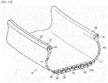
- FIG. 1A is a perspective view illustrating a cross-section of a part of a tire 10 according to the present embodiment.
- FIG. 1B is a cross-sectional view of a bead portion of the tire 10 according to the present embodiment being attached to a rim.
- the tire 10 has a cross-sectional shape that is substantially the same as that of a conventional and common rubber-made pneumatic tire.
- the tire 10 has a tire case 17 that includes a pair of bead portions 12, which are each in contact with a bead sheet 21 and a rim flange 22 of a rim 20 illustrated in FIG. 1B ; side portions 14, which extend from the bead portions 12 toward the outer side along a radial direction of the tire; and a crown portion 16 (outer circumferential portion), which connects the outer ends in the radial direction of the side portions 14.
- the tire case 17 corresponds to the above-described tire frame, and is formed from the above-described resin material. Although the tire case 17 is entirely formed from the above-described resin material in the embodiment, the disclosure is not restricted to this configuration and different resin materials may be used for respective parts (e.g., side portions 14, crown portion 16 and bead portions 12) as with a case of a conventional rubber-made pneumatic tire. Further, a reinforcing material (e.g., a fiber, a cord, a nonwoven fabric, or a woven fabric, which is made of a polymer material or a metal) may be embedded in order to reinforce each part of the tire case 17.
- a reinforcing material e.g., a fiber, a cord, a nonwoven fabric, or a woven fabric, which is made of a polymer material or a metal
- the tire case 17 is formed by preparing two tire case half sections (i.e., tire frame pieces) each having a shape of the tire case 17 being divided at the center of the tread width in the circumferential direction, and bonding them together at the tire equatorial plane.
- the tire case 17 is not restricted to that formed from two members, and may be formed from three or more members.
- the tire case half sections can be prepared by, for example, vacuum molding, pressure molding, injection molding, or melt casting. Accordingly, as compared to a conventional case where a tire case is molded from a rubber, the production process can be greatly simplified and the time for molding can be saved because it is not necessary to perform vulcanization.
- an annular bead core 18 is embedded in the bead portion 12 illustrated in FIG. 1B .
- a steel cord is used as the bead core 18 in the embodiment, an organic fiber cord, an organic fiber cord having a resin layer, a hard resin cord or the like may be used as well.
- the bead core 18 may be omitted when sufficient rigidity of the bead portion 12 is ensured and there is no problem in fitting of the bead portion 12 with the rim 20.
- the sealing layer 24 may be formed also at portions where the tire case 17 (bead portion 12) is in contact with the bead sheet 21.
- the sealing layer 24 may be omitted when the resin material that forms the tire case 17 can ensure sufficient sealing with the rim 20.
- the material having superior sealing performance than the resin material that forms the tire case 17 include a material that is softer than the resin material that forms the tire case 17, such as rubber, and thermoplastic resins and thermoplastic elastomers that are softer than the resin material.
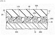
- a reinforcing cord 26 corresponding to the metal-resin composite member is wound around the crown portion 16 of the tire case 17 along a circumferential direction.
- the reinforcing cord 26 is disposed in a spiral manner while at least a part thereof is embedded in the crown portion 16, and forms a reinforcing cord layer 28.
- a tread 30 composed of a material having superior wear resistance than the resin material constituting the tire case 17, such as a rubber, is disposed.
- the reinforcing cord 26 is in a state where a metal member 26A such as a steel cord is covered with a coating resin (resin mixture) 27 (i.e., a coated cord member).
- a coating resin (resin mixture) 27 i.e., a coated cord member.
- the reinforcing cord 26 and the crown portion 16 are bonded by a method such as welding or using an adhesive.
- the reinforcing cord 26 has a substantially trapezoidal cross-sectional shape.
- the upper surface of the reinforcing cord 26 (the surface at the outer side in a radial direction of the tire) is indicated by 26U
- the lower surface of the reinforcing cord 26 (the surface at the inner side in a radial direction of the tire) is indicated by 26D.
- the reinforcing cord 26 has a substantially trapezoidal cross-sectional shape in the embodiment, the disclosure is not restricted to this constitution.
- the reinforcing cord 26 may be in any shape, except a shape in which the width of a cross-sectional shape increases from the side of the lower surface 26D (inner side in the radial direction of the tire) toward the upper surface 26U (outer side in the radial direction of the tire).
- gaps 28A are formed between adjacent reinforcing cords 26 along a circumferential direction. Accordingly, the outer circumferential surface of the reinforcing cord layer 28 has an irregular shape, and an outer circumferential surface 17S of the tire case 17, which is formed by the reinforcing cord layer 28, also has an irregular shape.
- the outer circumferential surface 17S (including the irregularities) of the tire case 17 has finely roughened irregularities 96, and a cushion rubber 29 is bonded thereon with a bonding agent.
- the cushion rubber 29 fills the roughened irregularities 96 at a surface in contact with the reinforcing cord 26.
- the above-described tread 30 is bonded on the cushion rubber 29 (the outer circumferential surface side).
- a tread pattern (not illustrated) constituted by plural grooves is formed in the same manner as in a conventional rubber-made pneumatic tire.
- a method of producing the tire of the present embodiment is not particularly restricted.
- the tire of the present invention may be produced by sequentially performing, for example, the tire case molding step, reinforcing cord member winding step, roughening treatment step, layering step, and vulcanization step, which are described below, in this order.
- tire case half sections supported by a thin metal support ring, are positioned to face each other.
- a bonding mold is set such that it comes into contact with the outer circumferential surfaces of the tire case half sections at which the same are facing each other.
- the bonding mold is configured to press the regions around the bonding portions (abutting portions) of the tire case half sections with a prescribed pressure.
- the regions around the bonding portions of the tire case half sections are pressed at a temperature of not lower than the melting points of the resin layer of the reinforcing cord and the resin material constituting the tire case, whereby the bonding portions are melted and the tire case half sections are integrated to form the tire case 17.
- the bonding portions of the tire case half sections are heated using a bonding mold
- the disclosure is not restricted thereto.
- the tire case half sections may be bonded together by heating the bonding portions using a high-frequency heater or the like, or softening or melting the bonding portions in advance by hot air, irradiation with infrared radiation or the like, and subsequently applying a pressure to the bonding portions using a bonding mold.
- FIG. 3 is a drawing for explaining operations of embedding the reinforcing cord 26 in the crown portion of the tire case 17 using a cord heating device and rollers.
- a cord feeding apparatus 56 includes a reel 58, around which the reinforcing cord 26 is wound; a cord heating device 59, which is disposed downstream of the reel 58 in the cord transfer direction; a first roller 60, which is disposed downstream in the transfer direction of the reinforcing cord 26; a first cylinder device 62, which moves the first roller 60 in a direction toward or away from the outer circumferential surface of the tire; a second roller 64, which is disposed downstream of the first roller 60 in the transfer direction of the reinforcing cord 26; and a second cylinder device 66, which moves the second roller 64 in a direction toward or away from the outer circumferential surface of the tire.
- the second roller 64 may be made of metal and used as a cooling roller.
- the surface of the first roller 60 or the surface of the second roller 64 may be subjected to a treatment for inhibiting adhesion of the melted or softened coating resin material 27 (such as a fluorine resin coating).
- the rollers may be formed from a material to which the coating resin material 27 is less likely to attach.
- the cord feeding apparatus 56 may have only one of these rollers.
- the cord heating device 59 includes a heater 70 and a fan 72, which generate a hot air flow.
- the cord heating device 59 further includes a heating box 74, having an inner space for the reinforcing cord 26 to pass, to which the hot air flow is supplied; and a discharge outlet 76 from which the heated reinforcing cord 26 is discharged.
- the temperature of the heater 70 of the cord heating device 59 is increased, and the ambient air that has been heated by the heater 70 is introduced into the heating box 74 with an air flow generated by rotation of the fan 72. Then, the reinforcing cord 26 that has been reeled out from the reel 58 is transferred to the heating box 74 with an inner space that has been heated with the hot air flow, whereby the reinforcing cord 26 is heated.
- the heating temperature is adjusted such that the coating resin 27 of the reinforcing cord 26 becomes molten or softened.
- the heated reinforcing cord 26 passes through the discharge outlet 76, and is spirally wound around the outer circumferential surface of the crown portion 16 of the tire case 17 rotating in the direction of an arrow R as illustrated in FIG. 3 , while applying a constant tension.
- the lower surface 26D of the reinforcing cord 26 is brought into contact with the outer circumferential surface of the crown portion 16.
- the bonding strength between the crown portion 16 and the reinforcing cord 26 is improved.
- the bonding may be performed by other methods as well.
- the bonding may be performed such that the reinforcing cord 26 is partially or entirely embedded in the crown portion 16.
- a blasting abrasive is ejected at high speed toward the outer circumferential surface 17S of the tire case 17 while rotating the same.
- the ejected blasting abrasive collides with the outer circumferential surface 17S to form finely roughened irregularities 96, which have an arithmetic average roughness (Ra) of not less than 0.05 mm, at the outer circumferential surface 17S.
- Ra arithmetic average roughness
- a bonding agent for bonding the cushion rubber 29 is applied onto the roughened outer circumferential surface 17S of the tire case 17.
- the bonding agent is not particularly restricted and, for example, a triazine thiol adhesive, a chlorinated rubber adhesive, a phenolic resin adhesive, an isocyanate adhesive, a halogenated rubber adhesive, or a rubber adhesive can be used.
- the bonding agent is preferably capable of reacting at a temperature at which the cushion rubber 29 can be vulcanized (from 90°C to 140°C).
- the cushion rubber 29, which is in an unvulcanized state is disposed around the outer circumferential surface 17S to which the bonding agent has been applied, and a bonding agent such as a rubber cement composition is applied onto the cushion rubber 29.
- a tread rubber 30A which is in a vulcanized or semi-vulcanized state, is disposed on the cushion rubber 29 to which the bonding agent has thus been applied, whereby a green tire case is obtained.
- the green tire case is vulcanized in a vulcanization can or a mold.
- the unvulcanized cushion rubber 29 flows to fill the roughened irregularities 96 that have been formed on the outer circumferential surface 17S of the tire case 17 by the roughening treatment.
- an anchoring effect is exerted by the cushion rubber 29 filling the roughened irregularities 96, and the bonding strength between the tire case 17 and the cushion rubber 29 is improved.
- the bonding strength between the tire case 17 and the tread 30 is improved by means of the cushion rubber 29.
- sealing layer 24 is attached to the bead portion 12 of the tire case 17 using an adhesive or the like, whereby the tire 10 is completed.
- an adhesive layer was formed using an acid-modified polyester thermoplastic elastomer ("PRIMALLOY AP GQ730", manufactured by Mitsubishi Chemical Corporation). Then, a resin layer of 0.1 mm in minimum thickness was formed on the adhesive layer by extruding a resin mixture using an extruder, and cooling the same, thereby obtaining a metal-resin composite member.
- Tires of the Examples and the Comparative Examples having a tire frame as in the embodiments described above and the metal-resin composite member prepared in the above process being disposed on an outer circumferential portion of the tire frame, were produced by a known method.
- the resin layer and the tire frame were formed using the resins shown in Table 1 at the respective blending ratios (parts by mass). The details of the resins shown in Table 1 are as follows.
- the elastic modulus (E/MPa) of the resin used for the formation of the resin layer was measured in accordance with JIS K7113:1995. The results thereof are shown in Table 1.
- the melting point of the resin used for the formation of the resin layer (melting point
- metal-resin composite member After bonding the resin layer of the metal-resin composite member with the tire frame, metal-resin composite member was peeled off from the tire frame by holding the end with a pair of pliers. The state of the metal-resin composite member after the peeling was evaluated based on the following criteria. The metal-resin composite member with a greater evaluation number is considered to have excellent bondability. The results thereof are shown in Table 1.
- the tire with an air pressure set at 230 kPa (relative pressure) was placed on a flat belt tester and allowed to rotate at a rate corresponding to a running speed of 80 km/h to measure the lateral force upon application of a slip angle. Specifically, the lateral force at a slip angle of 0° and the lateral force at a slip angle of 1° were measured, and the difference between the measured values was indicated as an index with respect to the difference measured in the tire of Comparative Example 1, being 100. The index was used as an indicator of the cornering power and evaluated based on the following criteria. The tire with a greater number is considered to have excellent cornering power. The results thereof are shown in Table 1.
- the tires of the Examples in which the resin layer includes a polyester thermoplastic elastomer and an amorphous resin that has an ester bond and has a Tg of 40°C or higher, and the content ratio of the amorphous resin is not higher than 50% by mass, exhibit favorable results in both of the bondability and the cornering power.
- the tires in which the resin layer includes TPC1 and amorphous resin 1 exhibit an increased elastic modulus while suppressing the difference in meltig point ( ⁇ Tm) to be -1°C and -2°C, respectively, as compared to a case where the resin layer includes only TPC1 (Comparative Example 1).
- the tires of Examples 1 and 2 exhibit improved cornering power and favorable bondability with respect to the tire frame.
- the tires in which the resin layer is formed only of a polyester thermoplastic elastomer have a lower elastic modulus of the resin layer than the tires of the Examples, and exhibit inferior cornering power as compared with the tires of the Examples.
- the tire in which the resin layer includes TPC2 (Comparative Example 3), having a higher HS ratio and more rigid than TPC1 included in the resin layer of the tire of Comparative Example 1, has a greater difference in melting point ( ⁇ Tm) of 7°C, even though the elastic modulus is increased. As a result, while the cornering power is improved, bondability with respect to the tire frame is deteriorated.
- the tires in which the content ratio of the amorphous resin is greater than 50% by mass exhibit inferior bondability with respect to the tire frame, even though the cornering power is favorable.
- the tire in which the amorphous resin had a Tg of lower than 40°C (Comparative Example 6) has a lower elastic modulus and exhibits inferior cornering power than the Examples.
Landscapes
- Engineering & Computer Science (AREA)
- Mechanical Engineering (AREA)
- Tires In General (AREA)
Abstract
Description
- The present invention relates to a metal-resin composite member for tires, and a tire.
- In recent years, tires that include a tire main body (hereinafter, also referred to as a "tire frame") formed using a resin material in place of a conventional material such as a rubber, have been developed because of their lightweightedness, ease of molding, recyclability, and the like. For example, Patent Document 1 proposes a tire that includes a tire frame formed using a polyester thermoplastic resin as a resin material.
- Patent Document 1 describes heat-melting a portion of a metal cord (reinforcing member) coated with a thermoplastic resin of the same kind as the thermoplastic resin configuring the tire frame, to thereby bond the metal cord to the tire frame. By using the same kind of thermoplastic resins for the reinforcing member and the tire frame, favorable bondability is realized between the tire frame and the reinforcing cord.
- [Patent Document 1] Japanese Patent Application Laid-Open (
JP-A) No. 2012-46025 - From the standpoint of the cornering power (steering response) of a tire, it is effective to make the coating of the reinforcing member have a higher rigidity than the tire frame. However, when a resin material having a higher rigidity than the resin material of the tire frame is used for coating the reinforcing member, the bondability between the tire frame and the reinforcing member may deteriorate due to, for example, a difference in melting point.
- Therefore, the provision of a metal-resin composite member for tires, which has excellent bondability with a thermoplastic resin-containing tire frame and can improve the cornering power of tires, and a tire including this metal-resin composite member for tires, is desired.
- A metal-resin composite member for tires, the metal-resin composite member comprising: a metal cord; and a resin layer, wherein: the resin layer is formed from a resin mixture that contains a polyester thermoplastic elastomer and an ester bond-containing amorphous resin having a glass transition temperature (Tg) of 40°C or higher, and a content ratio of the amorphous resin is not higher than 50% by mass of the resin mixture.
- According to the invention, a metal-resin composite member for tires, which has excellent bondability with a thermoplastic resin-containing tire frame and can improve the cornering power of tires, and a tire including this metal-resin composite member for tires are provided.
-
-
FIG. 1A is a perspective view illustrating a cross-section of a part of a tire according to one embodiment of the present disclosure; -
FIG. 1B is a cross-sectional view of a bead portion attached to a rim; -
FIG. 2 is a cross-sectional view taken along a tire rotation axis, which illustrates a state where a reinforcing cord is embedded in a crown portion of a tire case of the tire according to the present embodiment; and -
FIG. 3 is a drawing for explaining operations of embedding the reinforcing cord in the crown portion of the tire case. - Specific embodiments of the disclosure are described below in detail; however, the disclosure is not restricted to the below-described embodiments by any means, and the disclosure can be carried out with modifications as appropriate within the scope of the disclosure.
- The term "resin" used herein is a concept that encompasses thermoplastic resins (including thermoplastic elastomers) and thermosetting resins, but not vulcanized rubbers.
- The term "thermoplastic elastomer" used herein refers to a polymer compound composed of a copolymer that includes a polymer that constitutes a hard segment that is crystalline and having a high melting point or a high cohesive strength; and a polymer that constitutes a soft segment that is amorphous and having a low glass transition temperature. The thermoplastic elastomer has a property to become softened and fluidized as the temperature is increased, but becomes relatively hard and strong when cooled, and exhibits rubber-like elasticity.
- In the present specification, the numerical ranges described as "from ... to ..." includes the lower limit value and the upper limit value, respectively.
- The term "step" used herein encompasses not only an independent step but also a step that cannot be clearly distinguished from other steps, as long as the intended purpose of the step is achieved.
- The metal-resin composite member for tires according to the disclosure (hereinafter, also referred to as the "metal-resin composite member") includes a metal cord and a resin layer, wherein the resin layer is formed from a resin mixture that contains a polyester thermoplastic elastomer and an ester bond-containing amorphous resin having a glass transition temperature (Tg) of 40°C or higher (hereinafter, also referred to as the "specific amorphous resin"), and a content ratio of the amorphous resin is not higher than 50% by mass of the resin mixture.
- The present inventors have found that a metal-resin composite member, which has a resin layer formed from a resin mixture that includes a polyester thermoplastic elastomer and a specific amorphous resin, exhibits a superior effect of improving the cornering power of a tire, as compared with a metal-resin composite member for tires that includes a resin layer formed only of a polyester thermoplastic elastomer. The reason for this is believed to be that the rigidity of the resin mixture is increased as a result of blending an amorphous resin having a Tg of 40°C or higher with a polyester thermoplastic elastomer.
- Further, the present inventors have found that the metal-resin composite member having the above-described constitution maintains favorable bondability with respect to a tire frame, as compared with a case of increasing the rigidity of a polyester thermoplastic elastomer by itself (for example, using a polyester thermoplastic elastomer having a higher rigidity). Although the reason for this is not necessarily clear, it is presumed that a resin mixture obtained by blending an amorphous resin not having a distinct melting point with a polyester thermoplastic elastomer is less likely to change the melting point thereof, as compared with a resin mixture in which a different polyester thermoplastic elastomer is used, thereby suppressing a gap in melting point with respect to a resin material that forms a tire frame.
- Moreover, by controlling the content ratio of the amorphous resin to be not higher than 50% by mass of the resin mixture, it is considered that compatibility with respect to the resin material in the tire frame is maintained, thereby suppressing deterioration in bondability.
the metal-resin composite member may be disposed, for example, at an outer circumferential portion (crown portion) of a tire frame. A method of disposing the metal-resin composite member at an outer circumferential portion of the tire frame is not particularly restricted. For example, the metal-resin composite member may be wound around the outer circumferential portion of the tire frame by the method performed in the embodiments described below. In this process, it is preferred to heat-melt the resin layer of the metal-resin composite member and the crown portion of the tire frame, thereby increasing the bondability thereof.
the metal-resin composite member may consist only of a metal cord and a resin layer, or may include a member other than the metal cord and the resin layer. For example, the metal-resin composite member may include an adhesive layer between the metal cord and the resin layer. - The cross-sectional shape of the metal-resin composite member is not particularly restricted and may be, for example, circular or quadrangular. From the standpoint of ease of disposing the metal-resin composite member at a crown portion of a tire frame, the cross-sectional shape of the metal-resin composite member is preferably quadrangular. The metal-resin composite member may include only a single metal cord or plural metal cords, for example, two metal cords.
- The details of the metal-resin composite member are described below, but the disclosure is not restricted thereto.
- The metal cord is not particularly restricted, and any metal cord that are generally used for the purpose of reinforcing a tire may be employed. Examples of the metal cord include a monofilament composed of a single metal cord (single strand), and a multifilament that is formed from twisted plural metal cords (twisted strand). The cross-sectional shape, the diameter and the like of the metal cord are not particularly restricted, and may be selected in accordance with the intended use and the like of the composite member. The material of the metal cord is not particularly restricted, and may be steel and the like.
- When the metal cord is a twisted strand of plural cords, the number of the cords is not particularly restricted. For example, the number of the cords may be from 2 to 10, preferably from 5 to 9.
- From the standpoint of reinforcing a tire while reducing the weight thereof, the diameter of the metal cord is preferably from 0.2 mm to 2 mm, more preferably from 0.8 mm to 1.6 mm.
- When the metal cord is a single cord, the diameter thereof is defined as a measured value of a diameter at a cross-section of the metal cord (the maximum value of a distance between the arbitrarily-selected two points on the outline of a cross-section of the metal cord). In a case in which the metal cord consists of plural cords, the diameter thereof is defined as a diameter of a circle that is smallest among the circles that include all of the cross-sections of the plural cords observed therein.
- The tensile elastic modulus (hereinafter, unless otherwise specified, the term "elastic modulus" used herein refers to a tensile elastic modulus) of the metal cord is usually approximately from 100,000 MPa to 300,000 MPa, preferably from 120,000 MPa to 270,000 MPa, more preferably from 150,000 MPa to 250,000 MPa. The tensile elastic modulus of the metal cord is calculated from the slope of a stress-strain curve that is obtained using a tensile tester with a ZWICK-type chuck.
- The elongation at break (tensile elongation at break) of the metal cord is usually approximately from 0.1% to 15%, preferably from 1% to 15%, more preferably from 1% to 10%. The tensile elongation at break of the metal cord can be determined from the strain based on a stress-strain curve that is obtained using a tensile tester with a ZWICK-type chuck.
- The resin layer is formed from a resin mixture that includes a polyester thermoplastic elastomer and a specific amorphous resin, and the content ratio of the specific amorphous resin is not higher than 50% by mass of the resin mixture.
- From the standpoint of bondability with respect to a tire frame, the content ratio of the specific amorphous resin in the resin mixture is not higher than 50% by mass, preferably not higher than 40% by mass, more preferably not higher than 30% by mass.
- The lower limit value of the content ratio of the specific amorphous resin in the resin mixture is not particularly restricted. From the standpoint of attaining a sufficient effect of improving the rigidity, it is preferably 10% by mass or higher, more preferably 20% by mass or higher, still more preferably 30% by mass or higher.
- The content ratio of the specific amorphous resin in the resin mixture can be examined by, for example, a nuclear magnetic resonance (NMR) method.
- The method of verifying whether or not the resin mixture includes a polyester thermoplastic elastomer and a specific amorphous resin is not particularly restricted, and examples thereof include thermal analysis or observation of a cross-section of the resin mixture.
- The melting point of the resin mixture is usually approximately from 100°C to 350°C. From the standpoints of durability and productivity of a tire, it is preferably approximately from 100°C to 250°C, more preferably from 120°C to 250°C.
- In the present specification, the melting point of the resin mixture is a value measured by differential scanning calorimetry (DSC) in accordance with JIS K7121:2012. The measurement can be performed using, for example, "DSC Q100" manufactured by TA Instruments Inc., at a sweeping rate of 10°C/min. When the resin mixture has two or more melting points, the melting point of a component with the greatest mass ratio in the resin mixture is regarded as the melting point of the resin mixture, which also applies to the melting point of the resin material that forms a tire frame as described below.
- The resin mixture may include a component other than a resin. Examples of the component include various kinds of fillers (e.g., silica, calcium carbonate and clay), age resistors, oils, plasticizers, color formers, and weather resistant agents. When the resin mixture include a component other than a resin, the total content ratio thereof is preferably not higher than 10% by mass, more preferably not higher than 5% by mass, of the total resin mixture.
- From the standpoint of improving the cornering power, the elastic modulus of the resin layer is preferably 400 MPa or higher. From the standpoint of durability, the elastic modulus of the resin layer is preferably 1,500 MPa or less. In the present specification, the elastic modulus of the resin layer and the tensile elastic modulus of a resin composition are the values measured in accordance with JIS K7113:1995.
- In the metal-resin composite member, the thickness of the resin layer is not particularly restricted. From the standpoint of water barrier property, the minimum thickness of the resin layer (at a portion with the smallest thickness) is preferably 1.3 mm or more. From the standpoint of durability, the maximum thickness of the resin layer (at a portion with the largest thickness) is preferably 5.0 mm or less.
- The term "amorphous resin" used herein refers to a thermoplastic resin that either has an extremely low degree of crystallization or does not become a crystallized state. The resin mixture may include only a single kind of the specific amorphous resin, or two or more kinds of the specific amorphous resins.
- From the standpoint of imparting the resin layer with sufficient rigidity, the Tg of the specific amorphous resin is 40°C or higher, preferably 60°C or higher, more preferably 80°C or higher. The Tg of the specific amorphous resin is a value measured by DSC in accordance with JIS K6240:2011. Specifically, the Tg is defined as a temperature at an intersection of an original baseline in DSC measurement and a tangent line at an inflection point. The measurement can be performed using, for example, "DSC Q100" manufactured by TA Instruments Inc., at a sweeping rate of 10°C/min.
- The specific amorphous resin has an ester bond, from the standpoint of compatibility with respect to a polyester thermoplastic elastomer. Examples of an amorphous resin having an ester bond include polyester thermoplastic resins, polycarbonate thermoplastic resins, and polyurethane thermoplastic resins.
- Examples of the commercially available products of the specific amorphous resin include amorphous polyester resins of the VYLON Series, manufactured by TOYOBO Co., Ltd.; amorphous polycarbonate resins of the NOVAREX Series, manufactured by Mitsubishi Engineering-Plastics Corporation; and amorphous polyester resins of the ALTESTER Series, manufactured by Mitsubishi Gas Chemical Co., Inc.
- The polyester thermoplastic elastomer is, for example, a polymer compound in which at least a polyester forms a hard segment that is crystalline and has a high melting point, and a soft segment that is amorphous and has a low glass transition temperature is formed from a different polymer. The resin mixture may include only a single kind of polyester thermoplastic elastomer, or may include two or more kinds thereof.
- The content ratio of the polyester thermoplastic elastomer in the resin mixture is preferably higher than 50% by mass, more preferably 60% by mass or more, still more preferably 70% by mass or more.
- Examples of a polyester that forms a hard segment of a polyester thermoplastic elastomer include an aromatic polyester. The aromatic polyester can be formed from, for example, an aromatic dicarboxylic acid or an ester-forming derivative thereof, and an aliphatic diol. The aromatic polyester is preferably polybutylene terephthalate, which is derived from terephthalic acid and/or dimethyl terephthalate and 1,4-butanediol; and may be a polyester derived from a dicarboxylic acid component (e.g., isophthalic acid, phthalic acid, naphthalene-2,6-dicarboxylic acid, naphthalene-2,7-dicarboxylic acid, diphenyl-4,4'-dicarboxylic acid, diphenoxyethane dicarboxylic acid, 5-sulfoisophthalic acid, or an ester-forming derivative thereof) and a diol having a molecular weight of 300 or less, such as an aliphatic diol (e.g., ethylene glycol, trimethylene glycol, pentamethylene glycol, hexamethylene glycol, neopentyl glycol, or decamethylene glycol), an alicyclic diol (e.g., 1,4-cyclohexane dimethanol or tricyclodecane dimethylol) or an aromatic diol (e.g., xylylene glycol, bis(p-hydroxy)diphenyl, bis(p-hydroxyphenyl)propane, 2,2-bis[4-(2-hydroxyethoxy)phenyl]propane, bis[4-(2-hydroxy)phenyl]sulfone, 1,1-bis[4-(2-hydroxyethoxy)phenyl]cyclohexane, 4,4'-dihydroxy-p-terphenyl, or 4,4'-dihydroxy-p-quaterphenyl), or may be a copolymerized polyester in which two or more kinds of these dicarboxylic acid components and diol components are used in combination. Further, for example, a polyfunctional carboxylic acid component, a polyfunctional oxyacid component or a polyfunctional hydroxy component, which has three or more functional groups, can be copolymerized at an amount of 5% by mole or less.
- Specific examples of the polyester that forms a hard segment include polyethylene terephthalate, polybutylene terephthalate, polymethylene terephthalate, polyethylene naphthalate and polybutylene naphthalate, among which polybutylene terephthalate is preferred.
- Examples of a polymer that forms a soft segment include an aliphatic polyester and an aliphatic polyether.
- Examples of the aliphatic polyether include poly(ethylene oxide) glycol, poly(propylene oxide) glycol, poly(tetramethylene oxide) glycol, poly(hexamethylene oxide) glycol, copolymers of ethylene oxide and propylene oxide, ethylene oxide-addition polymers of poly(propylene oxide) glycol, and copolymers of ethylene oxide and tetrahydrofuran.
- Examples of the aliphatic polyester include poly(ε-caprolactone), polyenantholactone, polycaprylolactone, polybutylene adipate, and polyethylene adipate.
- Among these aliphatic polyethers and aliphatic polyesters, from the standpoint of elastic properties of the resulting polyester block copolymer, poly(tetramethylene oxide) glycol, an ethylene oxide-adduct of poly(propylene oxide) glycol, poly(ε-caprolactone), polybutylene adipate and polyethylene adipate are preferred as the polymer that forms a soft segment.
- From the standpoints of toughness and flexibility at low temperature, the number-average molecular weight of the polymer that forms a soft segment is preferably from 300 to 6,000. Further, from the standpoint of moldability, the mass ratio (x:y) of the hard segment (x) and the soft segment (y) is preferably from 99:1 to 20:80, more preferably from 98:2 to 30:70.
- The polyester thermoplastic elastomer is preferably a polyester thermoplastic elastomer having a hard segment that is at least one selected from the group consisting of polybutylene terephthalate (PBT), polyethylene terephthalate (PET), polybutylene naphthalate (PBN) and polyethylene naphthalate (PEN); more preferably a polyester thermoplastic elastomer having a soft segment that is poly(ethylene oxide) glycol, such as a polytetramethylene glycol (PTMG).
- Examples of the commercially available products of a polyester thermoplastic elastomer include the HYTREL Series manufactured by DuPont-Toray Co., Ltd. (e.g., 3046, 5557, 6347, 4047 and 4767) and the PELPRENE Series manufactured by TOYOBO Co., Ltd. (e.g., P30B, P40B, P40H, P55B, P70B, P150B, P280B, P450B, P150M, S1001, S2001, S5001, S6001 and S9001).
- The resin mixture may include a resin other than the polyester thermoplastic elastomer and the specific amorphous resin (also referred to as the other resin). If the resin mixture includes the other resin, the total ratio of the polyester thermoplastic elastomer and the specific amorphous resin with respect to all resins is preferably 70% by mass or higher, more preferably 80% by mass or higher, still more preferably 90% by mass or higher.
- When the resin mixture include the other resin, from the standpoint of improving the rigidity of the resin layer while maintaining favorable bondability with respect to a tire frame, the resin mixture preferably includes a polyester thermoplastic resin. The term "polyester thermoplastic resin" used herein does not encompass the polyester thermoplastic elastomer as described above. The term "polyester thermoplastic resin" encompasses both of a resin consisting of only a structural unit corresponding to polyester, and a resin in which the content of a structural unit corresponding to polyester is 80% by mole or more, preferably 90% by mole or more, more preferably 95% by mole or more, with respect to the total structural units corresponding to polyester.
- When the resin mixture includes a polyester thermoplastic resin as the other resin, from the standpoint of ensuring favorable adhesion with respect to a tire frame, the polyester thermoplastic elastomer and the polyester thermoplastic resin preferably have similar structures. For example, when the hard segment of the polyester thermoplastic elastomer is polybutylene terephthalate, a polyester thermoplastic resin is preferably polybutylene terephthalate, polyethylene terephthalate, polybutylene naphthalate, polyethylene naphthalate or the like, more preferably polybutylene terephthalate.
- Examples of the commercially available products of the polyester thermoplastic resin include the DURANEX Series (e.g., 201AC, 2000 and 2002) manufactured by Polyplastics Co., Ltd., the NOVADURAN Series (e.g., 5010R5 and 5010R3-2) manufactured by Mitsubishi Engineering-Plastics Corporation, and the TORAYCON Series (e.g., 1401X06 and 1401X31) manufactured by Toray Industries, Inc.
- The metal-resin composite member may include an adhesive layer between the metal cord and the resin layer. The material of the adhesive layer is not particularly restricted, and examples thereof include thermoplastic resins (including thermoplastic resin elastomers). The adhesive layer may include only a single thermoplastic resin, or may include two or more kinds thereof.
- From the standpoint of adhesion with respect to the resin layer, the thermoplastic resin that forms the adhesive layer is preferably a thermoplastic resin that has a structural unit of the same kind as a hard segment of the polyester thermoplastic resin elastomer in the resin mixture that forms the resin layer. For example, the thermoplastic resin that forms the adhesive layer is preferably a polyester thermoplastic elastomer or a polyester thermoplastic resin.
- From the standpoint of adhesion with respect to the metal cord, the thermoplastic resin that forms the adhesive layer is preferably modified with a functional group, more preferably modified with an acidic functional group.
- The tire of the disclosure includes an annular tire frame and the above-described metal-resin composite member, which is disposed on an outer circumferential portion of the tire frame, wherein the tire frame is formed from a resin material containing a polyester thermoplastic resin.
- From the standpoints of running performance and durability of the tire, the resin material that forms the tire frame preferably includes at least a polyester thermoplastic elastomer as the polyester thermoplastic resin.
- From the standpoint of bondability between the resin layer of the metal-resin composite member and the tire frame, the structure of the polyester thermoplastic elastomer included in the resin mixture that forms the resin layer and the structure of the polyester thermoplastic resin included in the resin material that forms the tire frame are preferably as similar as possible. For example, when the hard segment of the polyester thermoplastic elastomer in the resin mixture that forms the resin layer is polybutylene terephthalate, the polyester thermoplastic resin in the resin material that forms the tire frame is preferably a thermoplastic elastomer having a hard segment that is polybutylene terephthalate, polybutylene naphthalate or the like, more preferably a thermoplastic elastomer having a hard segment that is polybutylene terephthalate.
- The melting point of the resin material is not particularly restricted, and is usually from 100°C to 350°C. From the standpoints of durability and productivity of the tire, the melting point of the resin material is preferably selected from 100°C to 250°C, more preferably selected from 120°C to 250°C.
- From the standpoint of bondability between the metal-resin composite member and the tire frame, a difference in melting point (ΔTm) between the resin mixture that forms the resin layer of the metal-resin composite member and the resin material that forms the tire frame is preferably 6°C or less, more preferably 3°C or less.
- The difference in melting point is defined as a value obtained by measuring the melting point of the resin mixture that forms the resin layer of the metal-resin composite member (melting point a) and the melting point of the resin used for the formation of the tire frame (melting point b) by DSC, and calculating the difference thereof (a - b; °C).
- Either one of the melting point of the resin mixture that forms the resin layer of the metal-resin composite member or the melting point of the resin material that forms the tire frame may be higher than the other. In the present specification, a melting point measured by DSC is regarded as the melting point of the resin mixture.
- The resin material that forms the tire frame may also include a resin other than the polyester thermoplastic resin. In this case, the ratio of the polyester thermoplastic resin with respect to the total resin is preferably 70% by mass or more, more preferably 80% by mass or more, still more preferably 90% by mass or more.
- Examples of the resin other than the polyester thermoplastic resin that is included in the resin material that forms the tire frame include thermoplastic elastomers, such as polyamide thermoplastic elastomers, olefin thermoplastic elastomers, polyurethane thermoplastic elastomers, and polystyrene thermoplastic elastomers; and thermoplastic resins that are composed of structural units corresponding to a hard segment of these thermoplastic elastomers, such as polyamide thermoplastic resins, olefin thermoplastic resins, polyurethane thermoplastic resins, and polystyrene thermoplastic resins.
- The resin material may also include a component other than the resin. Examples of the component include various fillers (e.g., silica, calcium carbonate and clay), age resistors, oils, plasticizers, color formers, and weather resistant agents. When the resin material include a component other than the resin, the total content ratio thereof is preferably not greater than 10% by mass, more preferably not greater than 5% by mass, with respect to the total mass of the resin material.
- The tensile elastic modulus, which is defined in JIS K7113:1995, of the resin material is preferably from 50 MPa to 1,000 MPa, more preferably from 50 MPa to 800 MPa, still more preferably from 50 MPa to 700 MPa. When the tensile elastic modulus of the resin material is from 50 MPa to 1,000 MPa, attachment of a rim to the tire can be efficiently performed while maintaining the shape of the tire frame.
- The tensile strength, which is defined in JIS K7113 (1995), of the resin material is usually approximately from 15 MPa to 70 MPa, preferably from 17 MPa to 60 MPa, more preferably from 20 MPa to 55 MPa.
- The tensile strength at yield, which is defined in JIS K7113 (1995), of the resin material is preferably 5 MPa or more, more preferably from 5 MPa to 20 MPa, still more preferably from 5 MPa to 17 MPa. When the tensile strength at yield of the resin material is 5 MPa or more, the tire can endure the deformation upon application of a load during running or the like.
- The tensile elongation at yield, which is defined in JIS K7113 (1995), of the resin material is preferably 10% or more, more preferably from 10% to 70%, still more preferably from 15% to 60%. When the tensile elongation at yield of the resin material is 10% or more, attachment to a rim can be performed favorably due to a large elastic region.
- The tensile elongation at break, which is defined in JIS K7113 (1995), of the resin material is preferably 50% or more, more preferably 100% or more, still more preferably 150% or more, most preferably 200% or more. When the tensile elongation at break of the resin material is 50% or more, attachment to a rim can be performed favorably and the tire becomes less likely to break against collision.
- The deflection temperature under load (0.45 MPa), which is defined in ISO75-2 or ASTM D648, of the resin material is preferably 50°C or more, more preferably from 50°C to 150°C, still more preferably from 50°C to 130°C. When the deflection temperature under load of the resin material is 50°C or more, deformation of the tire frame can be suppressed even in a case of performing vulcanization during the production of the tire.
- When the metal-resin composite member includes an adhesive layer between the metal cord and the resin layer, it is preferred that the Martens hardness (d1) of the tire frame, the Martens hardness (d2) of the resin layer, and the Martens hardness (d3) of the adhesive layer satisfy a relationship of d1 ≤ d2 < d3. When the Martens hardness of the resin layer is less than the Martens hardness of the adhesive layer, and is equal to or greater than the Martens hardness of the tire frame, the difference in rigidity between the resin material that forms the tire frame and the metal member is effectively reduced. As a result, durability of the tire can be further improved.
- In the following, an embodiment of the tire according to the disclosure will be described by referring to the drawings.
-
FIG. 1A is a perspective view illustrating a cross-section of a part of atire 10 according to the present embodiment.FIG. 1B is a cross-sectional view of a bead portion of thetire 10 according to the present embodiment being attached to a rim. As illustrated inFIG. 1A , thetire 10 has a cross-sectional shape that is substantially the same as that of a conventional and common rubber-made pneumatic tire. As illustrated inFIG. 1A , thetire 10 has atire case 17 that includes a pair ofbead portions 12, which are each in contact with abead sheet 21 and arim flange 22 of arim 20 illustrated inFIG. 1B ;side portions 14, which extend from thebead portions 12 toward the outer side along a radial direction of the tire; and a crown portion 16 (outer circumferential portion), which connects the outer ends in the radial direction of theside portions 14. - The
tire case 17 corresponds to the above-described tire frame, and is formed from the above-described resin material. Although thetire case 17 is entirely formed from the above-described resin material in the embodiment, the disclosure is not restricted to this configuration and different resin materials may be used for respective parts (e.g.,side portions 14,crown portion 16 and bead portions 12) as with a case of a conventional rubber-made pneumatic tire. Further, a reinforcing material (e.g., a fiber, a cord, a nonwoven fabric, or a woven fabric, which is made of a polymer material or a metal) may be embedded in order to reinforce each part of thetire case 17. - The
tire case 17 is formed by preparing two tire case half sections (i.e., tire frame pieces) each having a shape of thetire case 17 being divided at the center of the tread width in the circumferential direction, and bonding them together at the tire equatorial plane. Thetire case 17 is not restricted to that formed from two members, and may be formed from three or more members. - The tire case half sections can be prepared by, for example, vacuum molding, pressure molding, injection molding, or melt casting. Accordingly, as compared to a conventional case where a tire case is molded from a rubber, the production process can be greatly simplified and the time for molding can be saved because it is not necessary to perform vulcanization.
- In the present embodiment, as in a conventional pneumatic tire, an
annular bead core 18 is embedded in thebead portion 12 illustrated inFIG. 1B . Although a steel cord is used as thebead core 18 in the embodiment, an organic fiber cord, an organic fiber cord having a resin layer, a hard resin cord or the like may be used as well. Thebead core 18 may be omitted when sufficient rigidity of thebead portion 12 is ensured and there is no problem in fitting of thebead portion 12 with therim 20. - In the present embodiment, an
annular sealing layer 24, which is composed of a material having superior sealing performance than the resin material that forms thetire case 17, is formed at a portion of eachbead portion 12 that comes into contact with therim 20, or at least at a portion of eachbead portion 12 that comes into contact with therim flange 22 of therim 20. Thesealing layer 24 may be formed also at portions where the tire case 17 (bead portion 12) is in contact with thebead sheet 21. Thesealing layer 24 may be omitted when the resin material that forms thetire case 17 can ensure sufficient sealing with therim 20. Examples of the material having superior sealing performance than the resin material that forms thetire case 17 include a material that is softer than the resin material that forms thetire case 17, such as rubber, and thermoplastic resins and thermoplastic elastomers that are softer than the resin material. - As illustrated in
FIG. 1A , a reinforcingcord 26 corresponding to the metal-resin composite member is wound around thecrown portion 16 of thetire case 17 along a circumferential direction. When viewed at a cross-section along the axial direction of thetire case 17, the reinforcingcord 26 is disposed in a spiral manner while at least a part thereof is embedded in thecrown portion 16, and forms a reinforcingcord layer 28. At an outer side of the reinforcingcord layer 28, along a radial direction of the tire, atread 30 composed of a material having superior wear resistance than the resin material constituting thetire case 17, such as a rubber, is disposed. - In the present embodiment, as illustrated in
FIG. 2 , the reinforcingcord 26 is in a state where ametal member 26A such as a steel cord is covered with a coating resin (resin mixture) 27 (i.e., a coated cord member). The reinforcingcord 26 and thecrown portion 16 are bonded by a method such as welding or using an adhesive. - In the present embodiment, as illustrated in
FIG. 2 , the reinforcingcord 26 has a substantially trapezoidal cross-sectional shape. In the following descriptions, the upper surface of the reinforcing cord 26 (the surface at the outer side in a radial direction of the tire) is indicated by 26U, and the lower surface of the reinforcing cord 26 (the surface at the inner side in a radial direction of the tire) is indicated by 26D. Although the reinforcingcord 26 has a substantially trapezoidal cross-sectional shape in the embodiment, the disclosure is not restricted to this constitution. The reinforcingcord 26 may be in any shape, except a shape in which the width of a cross-sectional shape increases from the side of thelower surface 26D (inner side in the radial direction of the tire) toward theupper surface 26U (outer side in the radial direction of the tire). - As illustrated in
FIG. 2 ,gaps 28A are formed between adjacent reinforcingcords 26 along a circumferential direction. Accordingly, the outer circumferential surface of the reinforcingcord layer 28 has an irregular shape, and an outercircumferential surface 17S of thetire case 17, which is formed by the reinforcingcord layer 28, also has an irregular shape. - The outer
circumferential surface 17S (including the irregularities) of thetire case 17 has finely roughenedirregularities 96, and acushion rubber 29 is bonded thereon with a bonding agent. Thecushion rubber 29 fills the roughenedirregularities 96 at a surface in contact with the reinforcingcord 26. - On the cushion rubber 29 (the outer circumferential surface side), the above-described
tread 30 is bonded. On the surface of thetread 30 that is in contact with the road surface, a tread pattern (not illustrated) constituted by plural grooves is formed in the same manner as in a conventional rubber-made pneumatic tire. - A method of producing the tire of the present embodiment is not particularly restricted. The tire of the present invention may be produced by sequentially performing, for example, the tire case molding step, reinforcing cord member winding step, roughening treatment step, layering step, and vulcanization step, which are described below, in this order.
- First, tire case half sections, supported by a thin metal support ring, are positioned to face each other. Subsequently, a bonding mold is set such that it comes into contact with the outer circumferential surfaces of the tire case half sections at which the same are facing each other. The bonding mold is configured to press the regions around the bonding portions (abutting portions) of the tire case half sections with a prescribed pressure. Then, the regions around the bonding portions of the tire case half sections are pressed at a temperature of not lower than the melting points of the resin layer of the reinforcing cord and the resin material constituting the tire case, whereby the bonding portions are melted and the tire case half sections are integrated to form the
tire case 17. - In the present embodiment, although the bonding portions of the tire case half sections are heated using a bonding mold, the disclosure is not restricted thereto. For example, the tire case half sections may be bonded together by heating the bonding portions using a high-frequency heater or the like, or softening or melting the bonding portions in advance by hot air, irradiation with infrared radiation or the like, and subsequently applying a pressure to the bonding portions using a bonding mold.
- In the following, the step of winding the reinforcing
cord 26 around thetire case 17 will be described by referring toFIG. 3. FIG. 3 is a drawing for explaining operations of embedding the reinforcingcord 26 in the crown portion of thetire case 17 using a cord heating device and rollers. - In
FIG. 3 , acord feeding apparatus 56 includes areel 58, around which the reinforcingcord 26 is wound; acord heating device 59, which is disposed downstream of thereel 58 in the cord transfer direction; afirst roller 60, which is disposed downstream in the transfer direction of the reinforcingcord 26; afirst cylinder device 62, which moves thefirst roller 60 in a direction toward or away from the outer circumferential surface of the tire; asecond roller 64, which is disposed downstream of thefirst roller 60 in the transfer direction of the reinforcingcord 26; and asecond cylinder device 66, which moves thesecond roller 64 in a direction toward or away from the outer circumferential surface of the tire. Thesecond roller 64 may be made of metal and used as a cooling roller. - In the present embodiment, the surface of the
first roller 60 or the surface of thesecond roller 64 may be subjected to a treatment for inhibiting adhesion of the melted or softened coating resin material 27 (such as a fluorine resin coating). Alternatively, the rollers may be formed from a material to which thecoating resin material 27 is less likely to attach. In the present embodiment, although thecord feeding apparatus 56 has two rollers, i.e., thefirst roller 60 and thesecond roller 64, thecord feeding apparatus 56 may have only one of these rollers. - The
cord heating device 59 includes aheater 70 and afan 72, which generate a hot air flow. Thecord heating device 59 further includes aheating box 74, having an inner space for the reinforcingcord 26 to pass, to which the hot air flow is supplied; and adischarge outlet 76 from which the heated reinforcingcord 26 is discharged. - In this step, first, the temperature of the
heater 70 of thecord heating device 59 is increased, and the ambient air that has been heated by theheater 70 is introduced into theheating box 74 with an air flow generated by rotation of thefan 72. Then, the reinforcingcord 26 that has been reeled out from thereel 58 is transferred to theheating box 74 with an inner space that has been heated with the hot air flow, whereby the reinforcingcord 26 is heated. The heating temperature is adjusted such that thecoating resin 27 of the reinforcingcord 26 becomes molten or softened. - The heated reinforcing
cord 26 passes through thedischarge outlet 76, and is spirally wound around the outer circumferential surface of thecrown portion 16 of thetire case 17 rotating in the direction of an arrow R as illustrated inFIG. 3 , while applying a constant tension. In this process, thelower surface 26D of the reinforcingcord 26 is brought into contact with the outer circumferential surface of thecrown portion 16. Thecoating resin 27, which is melted or softened by heating, spreads over the outer circumferential surface of thecrown portion 16, whereby the reinforcingcord 26 is welded to the outer circumferential surface of thecrown portion 16. As a result, the bonding strength between thecrown portion 16 and the reinforcingcord 26 is improved. - In the present embodiment, although the reinforcing
cord 26 is bonded to the outer circumferential surface of thecrown portion 16 in the above-described manner, the bonding may be performed by other methods as well. For example, the bonding may be performed such that the reinforcingcord 26 is partially or entirely embedded in thecrown portion 16. - Subsequently, using a blasting apparatus that is not illustrated in the drawing, a blasting abrasive is ejected at high speed toward the outer
circumferential surface 17S of thetire case 17 while rotating the same. The ejected blasting abrasive collides with the outercircumferential surface 17S to form finely roughenedirregularities 96, which have an arithmetic average roughness (Ra) of not less than 0.05 mm, at the outercircumferential surface 17S. By the formation of the finely roughenedirregularities 96 on the outercircumferential surface 17S of thetire case 17, the outercircumferential surface 17S is hydrophilized, and wettability with respect to a bonding agent as described below is improved. - Next, a bonding agent for bonding the
cushion rubber 29 is applied onto the roughened outercircumferential surface 17S of thetire case 17. The bonding agent is not particularly restricted and, for example, a triazine thiol adhesive, a chlorinated rubber adhesive, a phenolic resin adhesive, an isocyanate adhesive, a halogenated rubber adhesive, or a rubber adhesive can be used. The bonding agent is preferably capable of reacting at a temperature at which thecushion rubber 29 can be vulcanized (from 90°C to 140°C). - Then, the
cushion rubber 29, which is in an unvulcanized state, is disposed around the outercircumferential surface 17S to which the bonding agent has been applied, and a bonding agent such as a rubber cement composition is applied onto thecushion rubber 29. Subsequently, atread rubber 30A, which is in a vulcanized or semi-vulcanized state, is disposed on thecushion rubber 29 to which the bonding agent has thus been applied, whereby a green tire case is obtained. - Next, the green tire case is vulcanized in a vulcanization can or a mold. In this process, the
unvulcanized cushion rubber 29 flows to fill the roughenedirregularities 96 that have been formed on the outercircumferential surface 17S of thetire case 17 by the roughening treatment. Once the vulcanization is completed, an anchoring effect is exerted by thecushion rubber 29 filling the roughenedirregularities 96, and the bonding strength between thetire case 17 and thecushion rubber 29 is improved. In other words, the bonding strength between thetire case 17 and thetread 30 is improved by means of thecushion rubber 29. - Thereafter, the above-described
sealing layer 24 is attached to thebead portion 12 of thetire case 17 using an adhesive or the like, whereby thetire 10 is completed. - The above-described embodiments may be implemented with various modifications without departing from the spirit of the disclosure. It is noted that the scope of the disclosure is not limited to these embodiments. For the details of embodiments that are applicable to the disclosure, reference can be made to, for example,
JP-A No. 2012-46031 - The scope of the disclosure also includes the following embodiments.
- <1> A metal-resin composite member for tires, the metal-resin composite member comprising:
- a metal cord; and
- a resin layer, wherein:
- the resin layer is formed from a resin mixture that contains a polyester thermoplastic elastomer and an ester bond-containing amorphous resin having a glass transition temperature (Tg) of 40°C or higher, and
- a content ratio of the amorphous resin is not higher than 50% by mass of the resin mixture.
- <2> The metal-resin composite member for tires according to <1>, wherein the amorphous resin is at least one selected from the group consisting of polyester thermoplastic resins and polycarbonate thermoplastic resins.
- <3> The metal-resin composite member for tires according to <1> or <2>, wherein the resin layer has an elastic modulus of 400 MPa or higher.
- <4> A tire, comprising:
- an annular tire frame; and
- the metal-resin composite member for tires according to any one of <1> to <3>, which is disposed on an outer circumferential portion of the tire frame,
- wherein the tire frame is formed from a resin material containing a polyester thermoplastic resin.
- <5> The tire according to <4>, wherein a difference in melting point between the resin material and the resin mixture is 6°C or less.
- <6> The tire according to <4> or <5>, wherein the polyester thermoplastic resin comprises a polyester thermoplastic elastomer.
- <7> The tire according to any one of <4> to <6>, wherein the metal-resin composite member for tires is disposed on the outer circumferential portion of the tire frame by winding.
- In the following, the disclosure will be described more concretely by way of the Examples, but the disclosure is not restricted thereto.
- On the outer circumference of a multifilament having an average diameter of 1.15 mm (a cord obtained by twisting five monofilaments of 0.35 mm in average diameter (made of steel, strength: 280 N, elongation: 3%)), an adhesive layer was formed using an acid-modified polyester thermoplastic elastomer ("PRIMALLOY AP GQ730", manufactured by Mitsubishi Chemical Corporation). Then, a resin layer of 0.1 mm in minimum thickness was formed on the adhesive layer by extruding a resin mixture using an extruder, and cooling the same, thereby obtaining a metal-resin composite member.
- Tires of the Examples and the Comparative Examples (tire size: 225/40R18), having a tire frame as in the embodiments described above and the metal-resin composite member prepared in the above process being disposed on an outer circumferential portion of the tire frame, were produced by a known method. The resin layer and the tire frame were formed using the resins shown in Table 1 at the respective blending ratios (parts by mass). The details of the resins shown in Table 1 are as follows.
-
- TPC1: polyester thermoplastic elastomer in which a hard segment is polybutylene terephthalate and a soft segment is polytetramethylene glycol ("HYTREL 5557" manufactured by DuPont-Toray Co., Ltd., HS (hard segment) ratio: 60.4% by mole)
- TPC2: polyester thermoplastic elastomer in which a hard segment is polybutylene terephthalate and a soft segment is polytetramethylene glycol ("HYTREL 6347" manufactured by DuPont-Toray Co., Ltd., HS ratio: 75% by mole)
- PBT1: polybutylene terephthalate ("TORAYCON 1401X06" manufactured by Toray Industries, Inc.)
-
- Amorphous resin 1: polyester thermoplastic resin ("VYLON 270" manufactured by TOYOBO Co., Ltd., Tg: 67°C)
- Amorphous resin 2: polycarbonate thermoplastic resin ("NOVAREX 7020IR" manufactured by Mitsubishi Engineering-Plastics Corporation, Tg: 120°C)
- Amorphous resin 3: styrene thermoplastic elastomer (SEBS) ("TUFTEC H1052" manufactured by Asahi Kasei Corporation, Tg: -47°C)
- The elastic modulus (E/MPa) of the resin used for the formation of the resin layer was measured in accordance with JIS K7113:1995. The results thereof are shown in Table 1.
- The melting point of the resin used for the formation of the resin layer (melting point
- a) and the melting point of the resin used for the formation of a tire frame (melting point b) were measured by DSC, and the difference in melting point (melting point a - melting point
- b) was regarded as the melting point difference (ΔTm, °C). The results thereof are shown in Table 1.
- After bonding the resin layer of the metal-resin composite member with the tire frame, metal-resin composite member was peeled off from the tire frame by holding the end with a pair of pliers. The state of the metal-resin composite member after the peeling was evaluated based on the following criteria. The metal-resin composite member with a greater evaluation number is considered to have excellent bondability. The results thereof are shown in Table 1.
-
- 4: The resin layer and the tire frame are not separated at an interface thereof, and the area of an interface at which the metal cord and the resin layer are separated is less than 80% of the whole interface.
- 3: The resin layer and the tire frame are not separated at an interface thereof, and the area of an interface at which the metal cord and the resin layer are separated is 60% or more and less than 80% of the whole interface.
- 2: The resin layer and the tire frame are not separated at an interface thereof, and the area of an interface at which the metal cord and the resin layer are separated is less than 60% of the whole interface.
- 1: The resin layer and the tire frame are separated at an interface thereof.
- The tire with an air pressure set at 230 kPa (relative pressure) was placed on a flat belt tester and allowed to rotate at a rate corresponding to a running speed of 80 km/h to measure the lateral force upon application of a slip angle. Specifically, the lateral force at a slip angle of 0° and the lateral force at a slip angle of 1° were measured, and the difference between the measured values was indicated as an index with respect to the difference measured in the tire of Comparative Example 1, being 100. The index was used as an indicator of the cornering power and evaluated based on the following criteria. The tire with a greater number is considered to have excellent cornering power. The results thereof are shown in Table 1.
-
- 4: The index is 110 or greater.
- 3: The index is 105 or greater and less than 110.
- 2: The index is 95 or greater and less than 105.
- 1: The index is less than 95.
- As shown in Table 1, the tires of the Examples, in which the resin layer includes a polyester thermoplastic elastomer and an amorphous resin that has an ester bond and has a Tg of 40°C or higher, and the content ratio of the amorphous resin is not higher than 50% by mass, exhibit favorable results in both of the bondability and the cornering power.
- The tires in which the resin layer includes TPC1 and amorphous resin 1 (Examples 1 and 2) exhibit an increased elastic modulus while suppressing the difference in meltig point (ΔTm) to be -1°C and -2°C, respectively, as compared to a case where the resin layer includes only TPC1 (Comparative Example 1). As a result, the tires of Examples 1 and 2 exhibit improved cornering power and favorable bondability with respect to the tire frame.
- The tires in which the resin layer is formed only of a polyester thermoplastic elastomer (Comparative Examples 1 and 2) have a lower elastic modulus of the resin layer than the tires of the Examples, and exhibit inferior cornering power as compared with the tires of the Examples.
- The tire in which the resin layer includes TPC2 (Comparative Example 3), having a higher HS ratio and more rigid than TPC1 included in the resin layer of the tire of Comparative Example 1, has a greater difference in melting point (ΔTm) of 7°C, even though the elastic modulus is increased. As a result, while the cornering power is improved, bondability with respect to the tire frame is deteriorated.
- The tires in which the content ratio of the amorphous resin is greater than 50% by mass (Comparative Examples 4 and 5) exhibit inferior bondability with respect to the tire frame, even though the cornering power is favorable.
- The tire in which the amorphous resin had a Tg of lower than 40°C (Comparative Example 6) has a lower elastic modulus and exhibits inferior cornering power than the Examples.
- 10: tire, 12: bead portion, 16: crown portion, 18: bead core, 20: rim, 21: bead sheet, 22: rim flange, 17: tire case, 24: sealing layer, 26: reinforcing cord, 26A: metal member, 27: coating resin, 28: reinforcing cord layer, 29: cushion rubber, 96: roughened irregularities, 30: tread
- The disclosure of Japanese Patent Application No.
2017-118595 - All the documents, patent applications and technical standards that are described in the present specification are hereby incorporated by reference to the same extent as if each individual document, patent application or technical standard is concretely and individually described to be incorporated by reference.
| Material | Comparative Example 1 | Comparative Example 2 | Comparative Example 3 | Example 1 | Example 2 | Comparative Example 4 | Example 3 | Example 4 | Comparative Example 5 | Example 5 | |
| Tire frame | TPC1 | 100 | 100 | 100 | 100 | 100 | 100 | 100 | 100 | 100 | 100 |
| TPC2 | 0 | 0 | 0 | 0 | 0 | 0 | 0 | 0 | 0 | 0 | |
| Resin layer | TPC1 | 100 | 50 | 0 | 80 | 60 | 40 | 80 | 60 | 40 | 40 |
| TPC2 | 0 | 50 | 100 | 0 | 0 | 0 | 0 | 0 | 0 | 40 | |
| PBT1 | 0 | 0 | 0 | 0 | 0 | 0 | 0 | 0 | 0 | 0 | |
| Amorphous resin 1 | 0 | 0 | 0 | 20 | 40 | 60 | 0 | 0 | 0 | 0 | |
| Amorphous resin 2 | 0 | 0 | 0 | 0 | 0 | 0 | 20 | 40 | 60 | 20 | |
| Amorphous resin 3 | 0 | 0 | 0 | 0 | 0 | 0 | 0 | 0 | 0 | 0 | |
| Resin layer thickness (µm) | 2.2 | 2.2 | 2.2 | 2.2 | 2.2 | 2.2 | 2.2 | 2.2 | 2.2 | 2.2 | |
| Elastic modulus (MPa) | 210 | 310 | 420 | 480 | 710 | 1,190 | 490 | 780 | 1,290 | 590 | |
| ΔTm (°C) | 0 | 4 | 7 | -1 | -2 | -2 | 0 | -1 | -2 | 1 | |
| Bondability | 3 | 2 | 1 | 3 | 4 | 2 | 4 | 4 | 2 | 3 | |
| Cornering power | 2 | 3 | 4 | 4 | 4 | 4 | 4 | 4 | 4 | 4 | |
| Material | Comparative Example 6 | Example 6 | Example 7 | Example 8 | Example 9 | Example 10 | Example 11 | Example 12 | Example 13 | ||
| Tire frame | 100 | 100 | 100 | 75 | 100 | 100 | 100 | 100 | 100 | 100 | |
| 0 | 0 | 0 | 25 | 0 | 0 | 0 | 0 | 0 | 0 | ||
| Resin layer | 80 | 100 | 60 | 0 | 0 | 60 | 50 | 50 | 0 | 0 | |
| 0 | 0 | 0 | 60 | 60 | 0 | 0 | 0 | 50 | 50 | ||
| 0 | 0 | 20 | 0 | 0 | 0 | 0 | 0 | 0 | 0 | ||
| 0 | 0 | 20 | 40 | 40 | 40 | 50 | 0 | 50 | 0 | ||
| 0 | 0 | 0 | 0 | 0 | 0 | 0 | 50 | 0 | 50 | ||
| 20 | 0 | 0 | 0 | 0 | 0 | 0 | 0 | 0 | 0 | ||
| Resin layer thickness (µm) | 2.2 | 2.2 | 2.2 | 2.2 | 1.8 | 2.2 | 2.2 | 2.2 | 2.2 | ||
| Elastic modulus (MPa) | 160 | 790 | 910 | 910 | 710 | 1,010 | 1,080 | 1,180 | 1,270 | ||
| ΔTm(°C) | 0 | -1 | 0 | 6 | -2 | -2 | -1 | 3 | 4 | ||
| Bondability | 3 | 3 | 4 | 3 | 4 | 4 | 4 | 3 | 3 | ||
| Cornering power | 1 | 4 | 4 | 4 | 4 | 4 | 4 | 4 | 4 | ||
Claims (7)
- A metal-resin composite member for tires, the metal-resin composite member comprising:a metal cord; anda resin layer, wherein:the resin layer is formed from a resin mixture that contains a polyester thermoplastic elastomer and an ester bond-containing amorphous resin having a glass transition temperature (Tg) of 40°C or higher, anda content ratio of the amorphous resin is not higher than 50% by mass of the resin mixture.
- The metal-resin composite member for tires according to claim 1, wherein the amorphous resin is at least one selected from the group consisting of polyester thermoplastic resins and polycarbonate thermoplastic resins.
- The metal-resin composite member for tires according to claim 1 or 2, wherein the resin layer has an elastic modulus of 400 MPa or higher.
- A tire, comprising:an annular tire frame; andthe metal-resin composite member for tires according to any one of claims 1 to 3, which is disposed on an outer circumferential portion of the tire frame,wherein the tire frame is formed from a resin material containing a polyester thermoplastic resin.
- The tire according to claim 4, wherein a difference in melting point between the resin material and the resin mixture is 6°C or less.
- The tire according to claim 4 or 5, wherein the polyester thermoplastic resin comprises a polyester thermoplastic elastomer.
- The tire according to any one of claims 4 to 6, wherein the metal-resin composite member for tires is disposed on the outer circumferential portion of the tire frame by winding.
Applications Claiming Priority (2)
| Application Number | Priority Date | Filing Date | Title |
|---|---|---|---|
| JP2017118595A JP6770926B2 (en) | 2017-06-16 | 2017-06-16 | Metal resin composite members for tires and tires |
| PCT/JP2018/013021 WO2018230097A1 (en) | 2017-06-16 | 2018-03-28 | Metal-resin composite member for tire, and tire |
Publications (2)
| Publication Number | Publication Date |
|---|---|
| EP3640045A1 true EP3640045A1 (en) | 2020-04-22 |
| EP3640045A4 EP3640045A4 (en) | 2021-03-17 |
Family
ID=64660589
Family Applications (1)
| Application Number | Title | Priority Date | Filing Date |
|---|---|---|---|
| EP18816962.7A Withdrawn EP3640045A4 (en) | 2017-06-16 | 2018-03-28 | Metal-resin composite member for tire, and tire |
Country Status (5)
| Country | Link |
|---|---|
| US (1) | US20200238763A1 (en) |
| EP (1) | EP3640045A4 (en) |
| JP (1) | JP6770926B2 (en) |
| CN (1) | CN110770037A (en) |
| WO (1) | WO2018230097A1 (en) |
Families Citing this family (2)
| Publication number | Priority date | Publication date | Assignee | Title |
|---|---|---|---|---|
| JP7692687B2 (en) * | 2020-02-26 | 2025-06-16 | 東レ・セラニーズ株式会社 | Thermoplastic elastomer resin composition |
| JP6973562B2 (en) * | 2020-05-14 | 2021-12-01 | 住友ゴム工業株式会社 | Thermoplastic Elastomer Compositions for Tires and Tires |
Family Cites Families (24)
| Publication number | Priority date | Publication date | Assignee | Title |
|---|---|---|---|---|
| JPS6147839A (en) * | 1984-08-14 | 1986-03-08 | 株式会社ブリヂストン | Tire reinforcing material |
| JPH0913842A (en) * | 1995-06-30 | 1997-01-14 | Nichibei Co Ltd | Code for blinds |
| US6329053B2 (en) * | 1999-07-28 | 2001-12-11 | Kolon Industries, Inc. | Polyester multifilamentary yarn for tire cords, dipped cord and production thereof |
| JP2001049077A (en) * | 1999-08-12 | 2001-02-20 | Jsr Corp | Resin composition and cured product thereof |
| US20060079624A1 (en) * | 2004-10-08 | 2006-04-13 | Hildeberto Nava | Crosslinkable polymer systems |
| CN101400851B (en) * | 2006-03-08 | 2012-05-30 | 株式会社普利司通 | Copper-coated steel wire for reinforcing rubber articles and method of manufacturing the same |
| CN101541564B (en) * | 2006-11-22 | 2012-03-28 | 倍耐力轮胎股份公司 | Tires with lightweight bead cores |
| US20090107609A1 (en) * | 2007-10-31 | 2009-04-30 | Walter Kevin Westgate | High Extensible Cut-Resistant Barrier |
| KR101059271B1 (en) * | 2008-11-06 | 2011-08-24 | 한국타이어 주식회사 | Inclined cord for carcass made of polyethylene terephthalate / polycarbonate polymer blend and radial tire using same |
| WO2010086043A1 (en) * | 2009-01-28 | 2010-08-05 | Nv Bekaert Sa | Crimped flat wire as core of oval cord |
| DE102010000014A1 (en) * | 2010-01-07 | 2011-07-14 | Continental Reifen Deutschland GmbH, 30165 | Vehicle tires |
| EP3254868B1 (en) * | 2010-08-25 | 2019-08-14 | Bridgestone Corporation | Tire, and tire manufacturing method |
| JP5619527B2 (en) | 2010-08-25 | 2014-11-05 | 株式会社ブリヂストン | tire |
| JP5901106B2 (en) | 2010-08-25 | 2016-04-06 | 株式会社ブリヂストン | tire |
| CN107264186B (en) * | 2010-08-25 | 2019-12-10 | 株式会社普利司通 | Tire and method for manufacturing tire |
| CN105566862B (en) * | 2010-08-25 | 2018-09-07 | 株式会社普利司通 | Tire and its manufacturing method |
| CN110077172A (en) * | 2011-10-26 | 2019-08-02 | 横滨橡胶株式会社 | Pneumatic tire |
| CN202543704U (en) * | 2012-02-17 | 2012-11-21 | 贝卡尔特公司 | Steel cord and synchronous belt comprising same |
| CN105143350B (en) * | 2013-04-16 | 2017-06-27 | 东洋纺株式会社 | Glass fiber-reinforced Amilan polyamide resin composition |
| JP6001719B2 (en) * | 2015-04-06 | 2016-10-05 | 株式会社ブリヂストン | tire |
| JP6014713B2 (en) * | 2015-05-18 | 2016-10-25 | 株式会社ブリヂストン | tire |
| CN113079324A (en) | 2015-07-10 | 2021-07-06 | 松下知识产权经营株式会社 | Image pickup apparatus |
| JP6178829B2 (en) * | 2015-11-25 | 2017-08-09 | 株式会社ブリヂストン | tire |
| JP6028083B2 (en) * | 2015-11-25 | 2016-11-16 | 株式会社ブリヂストン | tire |
-
2017
- 2017-06-16 JP JP2017118595A patent/JP6770926B2/en not_active Expired - Fee Related
-
2018
- 2018-03-28 CN CN201880039791.5A patent/CN110770037A/en active Pending
- 2018-03-28 WO PCT/JP2018/013021 patent/WO2018230097A1/en not_active Ceased
- 2018-03-28 EP EP18816962.7A patent/EP3640045A4/en not_active Withdrawn
-
2019
- 2019-11-28 US US16/699,067 patent/US20200238763A1/en not_active Abandoned
Also Published As
| Publication number | Publication date |
|---|---|
| JP6770926B2 (en) | 2020-10-21 |
| CN110770037A (en) | 2020-02-07 |
| WO2018230097A1 (en) | 2018-12-20 |
| US20200238763A1 (en) | 2020-07-30 |
| EP3640045A4 (en) | 2021-03-17 |
| JP2019001344A (en) | 2019-01-10 |
Similar Documents
| Publication | Publication Date | Title |
|---|---|---|
| JP5901106B2 (en) | tire | |
| US10821690B2 (en) | Tire and method for manufacturing tire | |
| CN104144800B (en) | Tire | |
| JP6028083B2 (en) | tire | |
| US20200238763A1 (en) | Metal-resin composite member for tires, and tire | |
| EP2815894B1 (en) | Tire | |
| JP5971889B2 (en) | tire | |
| JP2017095616A (en) | tire | |
| JP5778403B2 (en) | tire | |
| JP6014715B2 (en) | tire | |
| JP6001719B2 (en) | tire | |
| EP3702174B1 (en) | Metal resin composite member for tires, and tire | |
| CN110494300A (en) | Tires and tire manufacturing methods | |
| CN110546018B (en) | Tyre for vehicle wheels | |
| JP5836575B2 (en) | tire | |
| WO2017146038A1 (en) | Tire | |
| JP5813416B2 (en) | tire | |
| JP7688515B2 (en) | Method for manufacturing tire and tire frame | |
| JP5893242B2 (en) | Pneumatic tire and manufacturing method thereof | |
| US20220033644A1 (en) | Resin composition for tire, resin-metal composite member for tire, and tire | |
| JP6001698B2 (en) | Tire and tire manufacturing method | |
| JP2019001358A (en) | tire |
Legal Events
| Date | Code | Title | Description |
|---|---|---|---|
| STAA | Information on the status of an ep patent application or granted ep patent |
Free format text: STATUS: THE INTERNATIONAL PUBLICATION HAS BEEN MADE |
|
| PUAI | Public reference made under article 153(3) epc to a published international application that has entered the european phase |
Free format text: ORIGINAL CODE: 0009012 |
|
| STAA | Information on the status of an ep patent application or granted ep patent |
Free format text: STATUS: REQUEST FOR EXAMINATION WAS MADE |
|
| 17P | Request for examination filed |
Effective date: 20191128 |
|
| AK | Designated contracting states |
Kind code of ref document: A1 Designated state(s): AL AT BE BG CH CY CZ DE DK EE ES FI FR GB GR HR HU IE IS IT LI LT LU LV MC MK MT NL NO PL PT RO RS SE SI SK SM TR |
|
| AX | Request for extension of the european patent |
Extension state: BA ME |
|
| DAV | Request for validation of the european patent (deleted) | ||
| DAX | Request for extension of the european patent (deleted) | ||
| A4 | Supplementary search report drawn up and despatched |
Effective date: 20210217 |
|
| RIC1 | Information provided on ipc code assigned before grant |
Ipc: B60C 9/22 20060101ALI20210211BHEP Ipc: B60C 1/00 20060101AFI20210211BHEP Ipc: B60C 5/01 20060101ALI20210211BHEP Ipc: B60C 9/00 20060101ALI20210211BHEP |
|
| RIC1 | Information provided on ipc code assigned before grant |
Ipc: B60C 9/00 20060101ALI20211213BHEP Ipc: B60C 9/22 20060101ALI20211213BHEP Ipc: B60C 5/01 20060101ALI20211213BHEP Ipc: B60C 1/00 20060101AFI20211213BHEP |
|
| GRAP | Despatch of communication of intention to grant a patent |
Free format text: ORIGINAL CODE: EPIDOSNIGR1 |
|
| STAA | Information on the status of an ep patent application or granted ep patent |
Free format text: STATUS: GRANT OF PATENT IS INTENDED |
|
| INTG | Intention to grant announced |
Effective date: 20220201 |
|
| STAA | Information on the status of an ep patent application or granted ep patent |
Free format text: STATUS: THE APPLICATION IS DEEMED TO BE WITHDRAWN |
|
| 18D | Application deemed to be withdrawn |
Effective date: 20220614 |