EP3640012A1 - Method and system for reworking a composite laminate - Google Patents
Method and system for reworking a composite laminate Download PDFInfo
- Publication number
- EP3640012A1 EP3640012A1 EP18382747.6A EP18382747A EP3640012A1 EP 3640012 A1 EP3640012 A1 EP 3640012A1 EP 18382747 A EP18382747 A EP 18382747A EP 3640012 A1 EP3640012 A1 EP 3640012A1
- Authority
- EP
- European Patent Office
- Prior art keywords
- tape
- defective
- reworking
- catching
- composite
- Prior art date
- Legal status (The legal status is an assumption and is not a legal conclusion. Google has not performed a legal analysis and makes no representation as to the accuracy of the status listed.)
- Granted
Links
Images







Classifications
-
- B—PERFORMING OPERATIONS; TRANSPORTING
- B29—WORKING OF PLASTICS; WORKING OF SUBSTANCES IN A PLASTIC STATE IN GENERAL
- B29C—SHAPING OR JOINING OF PLASTICS; SHAPING OF MATERIAL IN A PLASTIC STATE, NOT OTHERWISE PROVIDED FOR; AFTER-TREATMENT OF THE SHAPED PRODUCTS, e.g. REPAIRING
- B29C70/00—Shaping composites, i.e. plastics material comprising reinforcements, fillers or preformed parts, e.g. inserts
- B29C70/04—Shaping composites, i.e. plastics material comprising reinforcements, fillers or preformed parts, e.g. inserts comprising reinforcements only, e.g. self-reinforcing plastics
- B29C70/28—Shaping operations therefor
- B29C70/30—Shaping by lay-up, i.e. applying fibres, tape or broadsheet on a mould, former or core; Shaping by spray-up, i.e. spraying of fibres on a mould, former or core
- B29C70/38—Automated lay-up, e.g. using robots, laying filaments according to predetermined patterns
- B29C70/386—Automated tape laying [ATL]
- B29C70/388—Tape placement heads, e.g. component parts, details or accessories
-
- B—PERFORMING OPERATIONS; TRANSPORTING
- B29—WORKING OF PLASTICS; WORKING OF SUBSTANCES IN A PLASTIC STATE IN GENERAL
- B29C—SHAPING OR JOINING OF PLASTICS; SHAPING OF MATERIAL IN A PLASTIC STATE, NOT OTHERWISE PROVIDED FOR; AFTER-TREATMENT OF THE SHAPED PRODUCTS, e.g. REPAIRING
- B29C70/00—Shaping composites, i.e. plastics material comprising reinforcements, fillers or preformed parts, e.g. inserts
- B29C70/04—Shaping composites, i.e. plastics material comprising reinforcements, fillers or preformed parts, e.g. inserts comprising reinforcements only, e.g. self-reinforcing plastics
- B29C70/28—Shaping operations therefor
- B29C70/30—Shaping by lay-up, i.e. applying fibres, tape or broadsheet on a mould, former or core; Shaping by spray-up, i.e. spraying of fibres on a mould, former or core
- B29C70/34—Shaping by lay-up, i.e. applying fibres, tape or broadsheet on a mould, former or core; Shaping by spray-up, i.e. spraying of fibres on a mould, former or core and shaping or impregnating by compression, i.e. combined with compressing after the lay-up operation
-
- B—PERFORMING OPERATIONS; TRANSPORTING
- B29—WORKING OF PLASTICS; WORKING OF SUBSTANCES IN A PLASTIC STATE IN GENERAL
- B29C—SHAPING OR JOINING OF PLASTICS; SHAPING OF MATERIAL IN A PLASTIC STATE, NOT OTHERWISE PROVIDED FOR; AFTER-TREATMENT OF THE SHAPED PRODUCTS, e.g. REPAIRING
- B29C70/00—Shaping composites, i.e. plastics material comprising reinforcements, fillers or preformed parts, e.g. inserts
- B29C70/04—Shaping composites, i.e. plastics material comprising reinforcements, fillers or preformed parts, e.g. inserts comprising reinforcements only, e.g. self-reinforcing plastics
- B29C70/28—Shaping operations therefor
- B29C70/30—Shaping by lay-up, i.e. applying fibres, tape or broadsheet on a mould, former or core; Shaping by spray-up, i.e. spraying of fibres on a mould, former or core
- B29C70/38—Automated lay-up, e.g. using robots, laying filaments according to predetermined patterns
- B29C70/386—Automated tape laying [ATL]
-
- B—PERFORMING OPERATIONS; TRANSPORTING
- B29—WORKING OF PLASTICS; WORKING OF SUBSTANCES IN A PLASTIC STATE IN GENERAL
- B29C—SHAPING OR JOINING OF PLASTICS; SHAPING OF MATERIAL IN A PLASTIC STATE, NOT OTHERWISE PROVIDED FOR; AFTER-TREATMENT OF THE SHAPED PRODUCTS, e.g. REPAIRING
- B29C70/00—Shaping composites, i.e. plastics material comprising reinforcements, fillers or preformed parts, e.g. inserts
- B29C70/04—Shaping composites, i.e. plastics material comprising reinforcements, fillers or preformed parts, e.g. inserts comprising reinforcements only, e.g. self-reinforcing plastics
- B29C70/28—Shaping operations therefor
- B29C70/54—Component parts, details or accessories; Auxiliary operations, e.g. feeding or storage of prepregs or SMC after impregnation or during ageing
-
- B—PERFORMING OPERATIONS; TRANSPORTING
- B29—WORKING OF PLASTICS; WORKING OF SUBSTANCES IN A PLASTIC STATE IN GENERAL
- B29C—SHAPING OR JOINING OF PLASTICS; SHAPING OF MATERIAL IN A PLASTIC STATE, NOT OTHERWISE PROVIDED FOR; AFTER-TREATMENT OF THE SHAPED PRODUCTS, e.g. REPAIRING
- B29C70/00—Shaping composites, i.e. plastics material comprising reinforcements, fillers or preformed parts, e.g. inserts
- B29C70/04—Shaping composites, i.e. plastics material comprising reinforcements, fillers or preformed parts, e.g. inserts comprising reinforcements only, e.g. self-reinforcing plastics
- B29C70/28—Shaping operations therefor
- B29C70/54—Component parts, details or accessories; Auxiliary operations, e.g. feeding or storage of prepregs or SMC after impregnation or during ageing
- B29C70/545—Perforating, cutting or machining during or after moulding
-
- B—PERFORMING OPERATIONS; TRANSPORTING
- B29—WORKING OF PLASTICS; WORKING OF SUBSTANCES IN A PLASTIC STATE IN GENERAL
- B29C—SHAPING OR JOINING OF PLASTICS; SHAPING OF MATERIAL IN A PLASTIC STATE, NOT OTHERWISE PROVIDED FOR; AFTER-TREATMENT OF THE SHAPED PRODUCTS, e.g. REPAIRING
- B29C73/00—Repairing of articles made from plastics or substances in a plastic state, e.g. of articles shaped or produced by using techniques covered by this subclass or subclass B29D
- B29C73/04—Repairing of articles made from plastics or substances in a plastic state, e.g. of articles shaped or produced by using techniques covered by this subclass or subclass B29D using preformed elements
- B29C73/10—Repairing of articles made from plastics or substances in a plastic state, e.g. of articles shaped or produced by using techniques covered by this subclass or subclass B29D using preformed elements using patches sealing on the surface of the article
- B29C73/12—Apparatus therefor, e.g. for applying
-
- B—PERFORMING OPERATIONS; TRANSPORTING
- B32—LAYERED PRODUCTS
- B32B—LAYERED PRODUCTS, i.e. PRODUCTS BUILT-UP OF STRATA OF FLAT OR NON-FLAT, e.g. CELLULAR OR HONEYCOMB, FORM
- B32B43/00—Operations specially adapted for layered products and not otherwise provided for, e.g. repairing; Apparatus therefor
-
- B—PERFORMING OPERATIONS; TRANSPORTING
- B32—LAYERED PRODUCTS
- B32B—LAYERED PRODUCTS, i.e. PRODUCTS BUILT-UP OF STRATA OF FLAT OR NON-FLAT, e.g. CELLULAR OR HONEYCOMB, FORM
- B32B5/00—Layered products characterised by the non- homogeneity or physical structure, i.e. comprising a fibrous, filamentary, particulate or foam layer; Layered products characterised by having a layer differing constitutionally or physically in different parts
- B32B5/22—Layered products characterised by the non- homogeneity or physical structure, i.e. comprising a fibrous, filamentary, particulate or foam layer; Layered products characterised by having a layer differing constitutionally or physically in different parts characterised by the presence of two or more layers which are next to each other and are fibrous, filamentary, formed of particles or foamed
- B32B5/24—Layered products characterised by the non- homogeneity or physical structure, i.e. comprising a fibrous, filamentary, particulate or foam layer; Layered products characterised by having a layer differing constitutionally or physically in different parts characterised by the presence of two or more layers which are next to each other and are fibrous, filamentary, formed of particles or foamed one layer being a fibrous or filamentary layer
- B32B5/26—Layered products characterised by the non- homogeneity or physical structure, i.e. comprising a fibrous, filamentary, particulate or foam layer; Layered products characterised by having a layer differing constitutionally or physically in different parts characterised by the presence of two or more layers which are next to each other and are fibrous, filamentary, formed of particles or foamed one layer being a fibrous or filamentary layer another layer next to it also being fibrous or filamentary
-
- B—PERFORMING OPERATIONS; TRANSPORTING
- B29—WORKING OF PLASTICS; WORKING OF SUBSTANCES IN A PLASTIC STATE IN GENERAL
- B29C—SHAPING OR JOINING OF PLASTICS; SHAPING OF MATERIAL IN A PLASTIC STATE, NOT OTHERWISE PROVIDED FOR; AFTER-TREATMENT OF THE SHAPED PRODUCTS, e.g. REPAIRING
- B29C2793/00—Shaping techniques involving a cutting or machining operation
- B29C2793/0081—Shaping techniques involving a cutting or machining operation before shaping
-
- B—PERFORMING OPERATIONS; TRANSPORTING
- B32—LAYERED PRODUCTS
- B32B—LAYERED PRODUCTS, i.e. PRODUCTS BUILT-UP OF STRATA OF FLAT OR NON-FLAT, e.g. CELLULAR OR HONEYCOMB, FORM
- B32B41/00—Arrangements for controlling or monitoring lamination processes; Safety arrangements
- B32B2041/04—Detecting wrong registration, misalignment, deviation, failure
-
- B—PERFORMING OPERATIONS; TRANSPORTING
- B32—LAYERED PRODUCTS
- B32B—LAYERED PRODUCTS, i.e. PRODUCTS BUILT-UP OF STRATA OF FLAT OR NON-FLAT, e.g. CELLULAR OR HONEYCOMB, FORM
- B32B2260/00—Layered product comprising an impregnated, embedded, or bonded layer wherein the layer comprises an impregnation, embedding, or binder material
- B32B2260/02—Composition of the impregnated, bonded or embedded layer
- B32B2260/021—Fibrous or filamentary layer
-
- B—PERFORMING OPERATIONS; TRANSPORTING
- B32—LAYERED PRODUCTS
- B32B—LAYERED PRODUCTS, i.e. PRODUCTS BUILT-UP OF STRATA OF FLAT OR NON-FLAT, e.g. CELLULAR OR HONEYCOMB, FORM
- B32B2260/00—Layered product comprising an impregnated, embedded, or bonded layer wherein the layer comprises an impregnation, embedding, or binder material
- B32B2260/04—Impregnation, embedding, or binder material
- B32B2260/046—Synthetic resin
-
- B—PERFORMING OPERATIONS; TRANSPORTING
- B32—LAYERED PRODUCTS
- B32B—LAYERED PRODUCTS, i.e. PRODUCTS BUILT-UP OF STRATA OF FLAT OR NON-FLAT, e.g. CELLULAR OR HONEYCOMB, FORM
- B32B2305/00—Condition, form or state of the layers or laminate
- B32B2305/08—Reinforcements
-
- B—PERFORMING OPERATIONS; TRANSPORTING
- B32—LAYERED PRODUCTS
- B32B—LAYERED PRODUCTS, i.e. PRODUCTS BUILT-UP OF STRATA OF FLAT OR NON-FLAT, e.g. CELLULAR OR HONEYCOMB, FORM
- B32B2605/00—Vehicles
- B32B2605/18—Aircraft
Definitions
- the invention relates to the automated manufacturing of fibre reinforced composite laminates by using automated tape or tow placement machines.
- the invention is applicable to all the parts of the structure of an aircraft or any composite part out of aerospace field.
- Laminates comprising a plurality of plies of composite are known, these laminates are being laid up by an automated tape placement machine comprising a laying head which lays one tape or a plurality of tapes per trajectory of the laying head.
- the plurality of tapes laid in a trajectory are usually named as course.
- Figure 1 shows a schematic of a typical tape placement machine end effector with two laying heads.
- the tape is clamped and cut using a blade or alternative system, for instance, in figure 2 the clamping is done using the adding rollers.
- the rework has to be done manually by an operator using a blade knife or other instrument to remove the defective tape.
- the replacement of the removed tapes can be then done manually or using again the automated placement machine.
- the object of the invention is the improvement of the automated process of manufacturing composite laminates.
- the advantages with respect to the prior art are the systematisation of the rework process, improving the quality of the laminate after the rework, the eventual lead time and labour savings and the enabling of full automation of the composite laying operations.
- the detection of the defect is performed simultaneously to the laying up process of the tape.
- the use of an online automated inspection system to detect the occurrence of a defect during the laying process is used, although the detection can have different levels of automation, from direct visual detection by an operator up to real time full automated defect detection/identification implying the coordination with a defect detection system.
- the lay-up process of the defective tape is continued until the end of the course, specifically extending an additional length over the predetermined or design length of the tape.
- the head of the machine could perform a movement to separate the laying head from the laminate, in one embodiment allowing the deployment of the rework system.
- the next operation will be catching and removal of the defective tape or tapes by the catching system itself.
- the rework system may retract to avoid interference with the laying heads and the replacement tapes will be laid by the machine as previously stated.
- the catching step and the cutting step may be performed in any order as long as the defective tape is cut and catch by the catching system.
- the reworking system object of the invention comprises the catching system comprising means configured for catching the defective tape when the occurrence of a defect on the tape or plurality of tapes is detected during the laying of the tape and comprising means for removing the caught defective tape from the laminate.
- the automated tape placement machine object of the invention therefore comprises a reworking system according to the above and further comprises:
- Figure 1 discloses a known automated taped placement machine manufacturing a laminate (1) over a mould (100) by laminating tapes (2) by means of two heads comprising at least a pressure roller (6), addition rollers (5) and cutters (50).
- the tape (2) is clamped using the adding rollers (5) and cut using a blade or alternative system to end the laying.
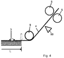
- Figure 3 shows the detection of a defect (3) on a tape (4) while the tape (4) is being laid up. Afterwards, the lay-up of the defective tape (4) is continued until a tape (4) length that surpasses the manufacturing length (L) of the tape (4) as represented in figure 4 . By rotation of the adding rollers (5) the defective tape (4) is placed between the pressure roller (6) and the laying surface to continue the lying operation.
- the catching system is deployed after detecting the occurrence of a defect (3) and retracted after removal of the defective tape (4).
- the lying head may be separated from the defective tape (4), more specifically, as shown in figure 5 , the pressure roller (6) is lifted from the laminate (1).
- the catching system of the embodiment shown in figure 6 comprises a clamp (7) with two jaws which traps the defective tape (4) to allow its removal.
- Figure 6 discloses two different embodiments, the clamp (7) being located below the pressure roller (6) or the clamp (7) being located over the pressure roller (6).
- the deployment of the jaws of the clamp (7) can be done by a longitudinal sliding movement, a rotational one, a telescopic extension or any other movement or combination of movements. These movements can be electric, pneumatic or any alternative considered appropriate.
- the catching step and the cutting step may be performed in any order:
- the removal of the defective tape (4) will be done by rewinding the defective tape (4) around the clamp (7) as shown in figure 9 , preferably at a speed coordinated with the backwards movement of the lying head. Finally, a replacement tape (2) is laid-up by the automated tape placement machine after removal of the defective tape (4) as shown in figure 10 .
- the clamp (7) comprises two external shells (9) and two internal cores (8) located in the shells (9) located in an opposite configuration and that behaves as a clamp to grab the defective tape (4).
- the internal cores (8) are movable with respect to the external shells (9) such that they trap the defective tape (4) in-between when approach each other and release the defective tape (4) when move away from each other.
- the clamp (7) comprises means for rewinding the defective tape (4) around the clamp (7), specifically, the defective tape (4) will be rewinded around the external shells (9) when the clamp (7) turns.
- Figure 11 shows a first step in which the clamp (7) has both internal cores (8) separated so that the defective tape (4) is located in-between
- figure 12 shows the internal cores (8) located against each other so that the defective tape (4) is caught by them and the turning of the clamp (7) makes the defective tape (4) to rewind over the external shells (9).
- Figure 13 shows the retraction of the inner cores (8) into the external shells (9) therefore liberating the defective tape (4).
- figure 14 shows one of the possible embodiments for releasing the defective tape (4) from the clamp (7) using a sliding arm (10) moving between the internal cores (8) in a direction parallel to the turning axis of the clamp (7) so that the sliding arm (10) pushes out the rolled defective tape (4).
- the release and remove steps would be preferably done in a scrap area located in the laying zone or integrated in the head or the structure of the machine, this last option reduces the number of movements of the machine but increase the size, weight and complexity of the machine so the solution will be adapted to each case.
Landscapes
- Engineering & Computer Science (AREA)
- Mechanical Engineering (AREA)
- Chemical & Material Sciences (AREA)
- Composite Materials (AREA)
- Robotics (AREA)
- Moulding By Coating Moulds (AREA)
- Lining Or Joining Of Plastics Or The Like (AREA)
Abstract
Description
- The invention relates to the automated manufacturing of fibre reinforced composite laminates by using automated tape or tow placement machines. The invention is applicable to all the parts of the structure of an aircraft or any composite part out of aerospace field.
- Laminates comprising a plurality of plies of composite are known, these laminates are being laid up by an automated tape placement machine comprising a laying head which lays one tape or a plurality of tapes per trajectory of the laying head. The plurality of tapes laid in a trajectory are usually named as course.
- Nowadays, the manufacturing process of fibre reinforced plastic parts, typically named as composite parts, is highly automated by using tape placement machines, both in the case of using resin preimpregnated tapes or dry tapes.
Figure 1 shows a schematic of a typical tape placement machine end effector with two laying heads. - In a tape placement machine, the movement of the machine itself allows the deposition of the tape. The action of a pressure roller and the eventual use of a heat source, whose presence and characteristics depends on the characteristics of the tape, allows the adherence of the tape to the laying tool or the laminate deposited in previous operations.
- To end the laying, the tape is clamped and cut using a blade or alternative system, for instance, in
figure 2 the clamping is done using the adding rollers. - Despite the high level of automation of the tape deposition, when a defect is detected during or after laying, the rework has to be done manually by an operator using a blade knife or other instrument to remove the defective tape. The replacement of the removed tapes can be then done manually or using again the automated placement machine.
- The object of the invention is the improvement of the automated process of manufacturing composite laminates. The advantages with respect to the prior art are the systematisation of the rework process, improving the quality of the laminate after the rework, the eventual lead time and labour savings and the enabling of full automation of the composite laying operations.
- It is one of the objects of the invention a method that comprises the following steps:
- detecting the occurrence of a defect on a tape of composite material while the tape is being laid up,
- continuing the lay-up of the defective tape until a tape length which surpasses a manufacturing length of the tape, i.e., a design length or a predetermined length at which the tape will be manufactured,
- catching the part of the defective tape that surpasses the manufacturing length of the tape by a catching system,
- cutting the defective tape by the automated tape placement machine in the part of the defective tape which surpasses the manufacturing length of the tape,
- removal from the laminate of the caught defective tape by the catching system, and
- laying-up a replacement tape by the automated tape placement machine after removal of the defective tape.
- According to the above, the detection of the defect is performed simultaneously to the laying up process of the tape. In one embodiment of the invention the use of an online automated inspection system to detect the occurrence of a defect during the laying process is used, although the detection can have different levels of automation, from direct visual detection by an operator up to real time full automated defect detection/identification implying the coordination with a defect detection system.
- Once the defect is detected, the lay-up process of the defective tape is continued until the end of the course, specifically extending an additional length over the predetermined or design length of the tape.
- In that moment, the head of the machine could perform a movement to separate the laying head from the laminate, in one embodiment allowing the deployment of the rework system.
- The next operation will be catching and removal of the defective tape or tapes by the catching system itself. When the tapes are removed, the rework system may retract to avoid interference with the laying heads and the replacement tapes will be laid by the machine as previously stated. The catching step and the cutting step may be performed in any order as long as the defective tape is cut and catch by the catching system.
- It is also an object of the present invention a reworking system and an automated tape placement machine comprising said reworking system.
- The reworking system object of the invention comprises the catching system comprising means configured for catching the defective tape when the occurrence of a defect on the tape or plurality of tapes is detected during the laying of the tape and comprising means for removing the caught defective tape from the laminate.
- The automated tape placement machine object of the invention therefore comprises a reworking system according to the above and further comprises:
- means for receiving a signal that a defect has occurred on a tape that is being laid-up,
- means for continuing the lay-up of a defective tape until a tape length which surpasses the manufacturing length of the tape,
- means for sending a signal to the reworking system for catching the part of the defective tape which surpasses the manufacturing length of the tape and for removing the defective tape,
- means for cutting the defective tape before being removed, and
- means for laying-up a replacement tape after removal of the defective tape.
- To complete the description and in order to provide for a better understanding of the invention, a set of drawings is provided. Said drawings form an integral part of the description and illustrate preferred embodiments of the invention. The drawings comprise the following figures.
-
Figure 1 shows a schematic representation of an automated tape placement machine. -
Figure 2 shows a schematic representation of the cutting process in an automated tape placement machine. -
Figure 3 shows a schematic representation of a first step of the invention in which a defect on a tape that is being laid is detected. -
Figure 4 shows a schematic representation of an additional step of the invention in which the laying-up process of the defective tape is continued until the end of a course. -
Figure 5 shows a schematic representation of a next step of the invention in which the pressure roller is separated from the laminate. -
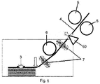
Figure 6 shows a schematic representation of a next step of the invention in which two different embodiments of the rework system catch the defective tape. -
Figures 7 y 8 shows a schematic representation of another embodiment in which the defective tape is firstly cut and afterwards the pressure roller is lifted from the laminate. -
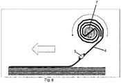
Figure 9 shows a schematic representation of a next step of the invention in which the rework system rewinds the tape for its removal. -
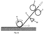
Figure 10 shows a schematic representation of a next step of the invention in which the defective tape is replaced by a new one. -
Figure 11 shows a schematic representation of an embodiment of the catching element of the rework system. -
Figure 12 shows a schematic representation of the rewind step of the catching element of the embodiment offigure 11 . -
Figure 13 shows a schematic representation of the release step of the catching element of the embodiment offigure 11 . -
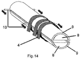
Figure 14 shows a schematic representation of the removal step of the catching element of the embodiment offigure 11 . -
Figure 1 discloses a known automated taped placement machine manufacturing a laminate (1) over a mould (100) by laminating tapes (2) by means of two heads comprising at least a pressure roller (6), addition rollers (5) and cutters (50). Infigure 2 the tape (2) is clamped using the adding rollers (5) and cut using a blade or alternative system to end the laying. -
Figure 3 shows the detection of a defect (3) on a tape (4) while the tape (4) is being laid up. Afterwards, the lay-up of the defective tape (4) is continued until a tape (4) length that surpasses the manufacturing length (L) of the tape (4) as represented infigure 4 . By rotation of the adding rollers (5) the defective tape (4) is placed between the pressure roller (6) and the laying surface to continue the lying operation. - In a multi-head machine, when laying multiple tapes (2), all the tapes (2) except the defective ones (4) are laid and cut according to the length of the original design of the part, except the defective ones (4) and those that may be selected to be also removed, that are extended an additional length. Therefore, the automated tape placement machine once a signal of a defected tape (4) is received continues the lay-up of a defective tape (4) until a tape (4) length that surpasses the manufacturing length (L) of the tape (4).
- In an embodiment, the catching system is deployed after detecting the occurrence of a defect (3) and retracted after removal of the defective tape (4). For allowing the mentioned deployment of the catching system, the lying head may be separated from the defective tape (4), more specifically, as shown in
figure 5 , the pressure roller (6) is lifted from the laminate (1). - The catching system of the embodiment shown in
figure 6 comprises a clamp (7) with two jaws which traps the defective tape (4) to allow its removal.Figure 6 discloses two different embodiments, the clamp (7) being located below the pressure roller (6) or the clamp (7) being located over the pressure roller (6). - The deployment of the jaws of the clamp (7) can be done by a longitudinal sliding movement, a rotational one, a telescopic extension or any other movement or combination of movements. These movements can be electric, pneumatic or any alternative considered appropriate.
- As previously commented, the catching step and the cutting step may be performed in any order:
- once the defective tape (4) or tapes (4) are clamped, the cutter (50) cuts them according to
figure 6 , or - alternatively, the defective tapes (4) to be removed are firstly cut and afterwards are clamped according to
figures 7 and8 . - The removal of the defective tape (4) will be done by rewinding the defective tape (4) around the clamp (7) as shown in
figure 9 , preferably at a speed coordinated with the backwards movement of the lying head. Finally, a replacement tape (2) is laid-up by the automated tape placement machine after removal of the defective tape (4) as shown infigure 10 . - As represented in the embodiment shown in
figures 11 to 14 , in order to have the catching system always ready for the next rework operation, it is advisable to allow an automated release of the removed defective tape (4). - In one embodiment, the clamp (7) comprises two external shells (9) and two internal cores (8) located in the shells (9) located in an opposite configuration and that behaves as a clamp to grab the defective tape (4). The internal cores (8) are movable with respect to the external shells (9) such that they trap the defective tape (4) in-between when approach each other and release the defective tape (4) when move away from each other. The clamp (7) comprises means for rewinding the defective tape (4) around the clamp (7), specifically, the defective tape (4) will be rewinded around the external shells (9) when the clamp (7) turns.
-
Figure 11 shows a first step in which the clamp (7) has both internal cores (8) separated so that the defective tape (4) is located in-between,figure 12 shows the internal cores (8) located against each other so that the defective tape (4) is caught by them and the turning of the clamp (7) makes the defective tape (4) to rewind over the external shells (9).Figure 13 shows the retraction of the inner cores (8) into the external shells (9) therefore liberating the defective tape (4). - Finally,
figure 14 shows one of the possible embodiments for releasing the defective tape (4) from the clamp (7) using a sliding arm (10) moving between the internal cores (8) in a direction parallel to the turning axis of the clamp (7) so that the sliding arm (10) pushes out the rolled defective tape (4). - The release and remove steps would be preferably done in a scrap area located in the laying zone or integrated in the head or the structure of the machine, this last option reduces the number of movements of the machine but increase the size, weight and complexity of the machine so the solution will be adapted to each case.
Claims (13)
- Method for reworking a composite laminate (1), the laminate (1) comprising a plurality of tapes (2) of composite that are being laid up by an automated tape placement machine comprising a lying head, characterised in that the method comprises the following steps:- detecting the occurrence of a defect (3) on a tape (4) of composite material while the tape (4) is being laid up,- continuing the lay-up of the defective tape (4) until a tape (4) length which surpasses a manufacturing length (L) of the tape (4),- catching the part of the defective tape (4) that surpasses the manufacturing length (L) of the tape (4) by a catching system,- cutting the defective tape (4) in the part of the defective tape (4) that surpasses the manufacturing length (L) of the tape (4),- removing from the laminate (1) the caught defective tape (4) by the catching system, and- after removal of the defective tape (4) laying-up a replacement tape (2) in the place of the removed defective tape (4) by the automated tape placement machine.
- Method for reworking a composite part, according to claim 1, wherein an automated inspection system is provided for detecting the occurrence of a defect (3).
- Method for reworking a composite part, according to any preceding claim, wherein the catching system will be deployed over the laminate (1) after detecting the occurrence of a defect (3) and retracted from the laminate (1) after removal of the defective tape (4).
- Method for reworking a composite part, according to claim 3, wherein before the deployment of the catching system, the lying head is separated from the defective tape (4).
- Method for reworking a composite part, according to any preceding claim, wherein the catching system comprises a clamp (7) with two jaws which trap the defective tape (4) in-between.
- Method for reworking a composite part, according to claim 5, wherein the removal of the defective tape (4) is done by rewinding the defective tape (4) around the clamp (7).
- Method for reworking a composite part, according to any preceding claim, wherein the defective tape (4) is cut after being caught by the catching system.
- Reworking system for a composite laminate (1) comprising a plurality of tapes (2) of composite configured for being laminated by an automated tape placement machine comprising a laying head characterised in that the reworking system comprises a catching system comprising means configured for catching a defective tape (4) when the occurrence of a defect (3) on the tape (4) is detected during the laying of the tape (4) and the catching system comprising means for removing the caught defective tape (4) from the laminate (1).
- Reworking system for a composite laminate, according to claim 8, wherein it comprises a clamp (7) with two jaws configured for trapping the defective tape (4) in-between.
- Reworking system for a composite laminate, according to claim 9, wherein the clamp (7) comprises means for rewinding the defective tape (4) around the clamp (7).
- Reworking system for a composite laminate, according to claim 8 or 9, wherein the clamp (7) comprises two external shells (9) and two internal cores (8) located in the external shells (9) and in an opposite location, the internal cores (8) being movable with respect to the external shells (9) such that they trap the defective tape (4) in-between when approaches each other and release the defective tape (4) when move away from each other.
- Reworking system for a composite laminate, according to claim 11, wherein the defective tape (4) is rewind around the external shells (9).
- Automated tape placement machine characterised in that it comprises a reworking system according to any preceding claim 8 to 12 and in that it further comprises:- means for receiving a signal that a defect (3) has occurred on a tape (4) that is being laid-up,- means for continuing the lay-up of a defective tape (4) until a tape (4) length that surpasses the manufacturing length (L) of the tape (4),- means for sending a signal to the reworking system for catching the part of the defective tape (4) that surpasses the manufacturing length (L) of the tape (4) and for removing the defective tape (4),- means (50) for cutting the defective tape (4) in the part of the defective tape (4) that surpasses the manufacturing length (L) of the tape (4) before being removed,- means for laying-up a replacement tape (2) after removal of the defective tape (4).
Priority Applications (5)
| Application Number | Priority Date | Filing Date | Title |
|---|---|---|---|
| EP18382747.6A EP3640012B1 (en) | 2018-10-19 | 2018-10-19 | Method and system for reworking a composite laminate |
| CA3056864A CA3056864A1 (en) | 2018-10-19 | 2019-09-26 | Method and system for reworking a composite laminate |
| KR1020190125755A KR102502355B1 (en) | 2018-10-19 | 2019-10-11 | Method and system for reworking a composite laminate |
| US16/655,414 US11104084B2 (en) | 2018-10-19 | 2019-10-17 | Method and system for reworking a composite laminate |
| CN201910994173.2A CN111070731B (en) | 2018-10-19 | 2019-10-18 | Method and system for reprocessing composite laminates and automatic tape laying machine |
Applications Claiming Priority (1)
| Application Number | Priority Date | Filing Date | Title |
|---|---|---|---|
| EP18382747.6A EP3640012B1 (en) | 2018-10-19 | 2018-10-19 | Method and system for reworking a composite laminate |
Publications (2)
| Publication Number | Publication Date |
|---|---|
| EP3640012A1 true EP3640012A1 (en) | 2020-04-22 |
| EP3640012B1 EP3640012B1 (en) | 2026-04-01 |
Family
ID=64426822
Family Applications (1)
| Application Number | Title | Priority Date | Filing Date |
|---|---|---|---|
| EP18382747.6A Active EP3640012B1 (en) | 2018-10-19 | 2018-10-19 | Method and system for reworking a composite laminate |
Country Status (5)
| Country | Link |
|---|---|
| US (1) | US11104084B2 (en) |
| EP (1) | EP3640012B1 (en) |
| KR (1) | KR102502355B1 (en) |
| CN (1) | CN111070731B (en) |
| CA (1) | CA3056864A1 (en) |
Families Citing this family (3)
| Publication number | Priority date | Publication date | Assignee | Title |
|---|---|---|---|---|
| ES2966314T3 (en) * | 2021-01-29 | 2024-04-19 | Airbus Operations Slu | Method for determining the peel energy of a composite laminate |
| CN113059829B (en) * | 2021-03-09 | 2022-03-25 | 北京航空航天大学 | Synchronous collecting mechanism for isolating films of thermosetting fiber prepreg tapes |
| US20240181665A1 (en) * | 2021-03-19 | 2024-06-06 | Vibracoustic Cv Air Spring Otomotiv Sanayi Ve Ticaret Anonim Sirketi | Automatic apparel machine |
Citations (2)
| Publication number | Priority date | Publication date | Assignee | Title |
|---|---|---|---|---|
| WO2012022972A2 (en) * | 2010-08-19 | 2012-02-23 | University Of Nottingham | An apparatus and method for the layup of sheets to form a composite article and composite articles made thereby |
| WO2016179616A1 (en) * | 2015-05-12 | 2016-11-17 | Fill Gesellschaft M.B.H. | Gripper having at least one clamping element |
Family Cites Families (8)
| Publication number | Priority date | Publication date | Assignee | Title |
|---|---|---|---|---|
| DE29706768U1 (en) * | 1997-04-15 | 1997-11-13 | EMTEC Magnetics GmbH, 67059 Ludwigshafen | Device for processing magnetic tapes |
| US20120247643A1 (en) * | 2005-10-28 | 2012-10-04 | The Boeing Company | Tape flaw and splice avoidance |
| US8158210B2 (en) * | 2005-10-28 | 2012-04-17 | The Boeing Company | Systems and methods for tape flaw and splice avoidance in manufacturing |
| KR200432365Y1 (en) | 2006-07-31 | 2006-12-04 | 전형일 | Blind Fabric Detachment Device of Blind System |
| CN102975375A (en) * | 2012-12-05 | 2013-03-20 | 成都飞机工业(集团)有限责任公司 | Method for detecting automated tape laying quality of composite material through laser positioning |
| CN104608398B (en) * | 2015-02-16 | 2017-03-01 | 徐剑 | A kind of laying method of fibrous composite parts preforming and equipment |
| US10502695B2 (en) * | 2017-08-16 | 2019-12-10 | The Boeing Company | Automated inspection of foreign materials, cracks and other surface anomalies |
| WO2020071466A1 (en) * | 2018-10-05 | 2020-04-09 | 福井県 | Automatic layering method and device for thin tape |
-
2018
- 2018-10-19 EP EP18382747.6A patent/EP3640012B1/en active Active
-
2019
- 2019-09-26 CA CA3056864A patent/CA3056864A1/en active Pending
- 2019-10-11 KR KR1020190125755A patent/KR102502355B1/en active Active
- 2019-10-17 US US16/655,414 patent/US11104084B2/en active Active
- 2019-10-18 CN CN201910994173.2A patent/CN111070731B/en active Active
Patent Citations (2)
| Publication number | Priority date | Publication date | Assignee | Title |
|---|---|---|---|---|
| WO2012022972A2 (en) * | 2010-08-19 | 2012-02-23 | University Of Nottingham | An apparatus and method for the layup of sheets to form a composite article and composite articles made thereby |
| WO2016179616A1 (en) * | 2015-05-12 | 2016-11-17 | Fill Gesellschaft M.B.H. | Gripper having at least one clamping element |
Also Published As
| Publication number | Publication date |
|---|---|
| KR102502355B1 (en) | 2023-02-21 |
| CN111070731A (en) | 2020-04-28 |
| CN111070731B (en) | 2023-07-18 |
| US11104084B2 (en) | 2021-08-31 |
| US20200122412A1 (en) | 2020-04-23 |
| EP3640012B1 (en) | 2026-04-01 |
| CA3056864A1 (en) | 2020-04-19 |
| KR20200045402A (en) | 2020-05-04 |
Similar Documents
| Publication | Publication Date | Title |
|---|---|---|
| US11104084B2 (en) | Method and system for reworking a composite laminate | |
| US9902584B2 (en) | Foil removal device and a method for removing a foil from a tire tread | |
| EP2823954B1 (en) | Short course fiber placement head | |
| US8256485B2 (en) | Device for separating and discharging trimmings cut in a pre-impregnated strip | |
| KR20140050085A (en) | System and method for making advanced composite laminates | |
| CN106956445B (en) | Cutter blade for an automatic fiber placement machine | |
| DE112009000844T5 (en) | Apparatus and method for stripping a film | |
| BR0303399B1 (en) | process and device for separating hoses. | |
| WO2019056746A1 (en) | Optical cable manufacturing method | |
| JP5215382B2 (en) | Composite material layup head with retractable separator for separating prepreg from support tape | |
| JP6654854B2 (en) | Wound body | |
| EP3566989B1 (en) | An equipment for attaching an optical fiber to a reel | |
| FI20185426A1 (en) | A single-reel winding device and a method for replacing a full reel in a single-reel winding device | |
| US20240298657A1 (en) | Apparatus for removing an outer covering from food products and the like | |
| JP3092775B2 (en) | Electric wire temporary bundling method and electric wire temporary bundling device | |
| EP4035875B1 (en) | Method for determining debonding energy of a composite laminate | |
| JP3822023B2 (en) | Coil trimming method and apparatus | |
| CN223863898U (en) | Automatic board device that divides of PCBA board | |
| CN103465301A (en) | Sheet edge-cutting automatic adjusting device and method of thermoplastic plate mould impregnation equipment | |
| CA2851680C (en) | Clip ejector | |
| CN119460861A (en) | High speed slitting machine | |
| JP2004058345A (en) | Method and device for removing defective part of cord strip |
Legal Events
| Date | Code | Title | Description |
|---|---|---|---|
| PUAI | Public reference made under article 153(3) epc to a published international application that has entered the european phase |
Free format text: ORIGINAL CODE: 0009012 |
|
| STAA | Information on the status of an ep patent application or granted ep patent |
Free format text: STATUS: THE APPLICATION HAS BEEN PUBLISHED |
|
| AK | Designated contracting states |
Kind code of ref document: A1 Designated state(s): AL AT BE BG CH CY CZ DE DK EE ES FI FR GB GR HR HU IE IS IT LI LT LU LV MC MK MT NL NO PL PT RO RS SE SI SK SM TR |
|
| AX | Request for extension of the european patent |
Extension state: BA ME |
|
| STAA | Information on the status of an ep patent application or granted ep patent |
Free format text: STATUS: REQUEST FOR EXAMINATION WAS MADE |
|
| 17P | Request for examination filed |
Effective date: 20201019 |
|
| RBV | Designated contracting states (corrected) |
Designated state(s): AL AT BE BG CH CY CZ DE DK EE ES FI FR GB GR HR HU IE IS IT LI LT LU LV MC MK MT NL NO PL PT RO RS SE SI SK SM TR |
|
| STAA | Information on the status of an ep patent application or granted ep patent |
Free format text: STATUS: EXAMINATION IS IN PROGRESS |
|
| 17Q | First examination report despatched |
Effective date: 20221110 |
|
| GRAP | Despatch of communication of intention to grant a patent |
Free format text: ORIGINAL CODE: EPIDOSNIGR1 |
|
| STAA | Information on the status of an ep patent application or granted ep patent |
Free format text: STATUS: GRANT OF PATENT IS INTENDED |
|
| INTG | Intention to grant announced |
Effective date: 20251021 |
|
| GRAS | Grant fee paid |
Free format text: ORIGINAL CODE: EPIDOSNIGR3 |
|
| GRAA | (expected) grant |
Free format text: ORIGINAL CODE: 0009210 |
|
| STAA | Information on the status of an ep patent application or granted ep patent |
Free format text: STATUS: THE PATENT HAS BEEN GRANTED |
|
| AK | Designated contracting states |
Kind code of ref document: B1 Designated state(s): AL AT BE BG CH CY CZ DE DK EE ES FI FR GB GR HR HU IE IS IT LI LT LU LV MC MK MT NL NO PL PT RO RS SE SI SK SM TR |
|
| REG | Reference to a national code |
Ref country code: CH Ref legal event code: F10 Free format text: ST27 STATUS EVENT CODE: U-0-0-F10-F00 (AS PROVIDED BY THE NATIONAL OFFICE) Effective date: 20260401 Ref country code: GB Ref legal event code: FG4D |
|
| REG | Reference to a national code |
Ref country code: IE Ref legal event code: FG4D |
|
| REG | Reference to a national code |
Ref country code: DE Ref legal event code: R096 Ref document number: 602018090189 Country of ref document: DE |