EP3639960A1 - Welding torch and welding torch cooling system - Google Patents
Welding torch and welding torch cooling system Download PDFInfo
- Publication number
- EP3639960A1 EP3639960A1 EP18816970.0A EP18816970A EP3639960A1 EP 3639960 A1 EP3639960 A1 EP 3639960A1 EP 18816970 A EP18816970 A EP 18816970A EP 3639960 A1 EP3639960 A1 EP 3639960A1
- Authority
- EP
- European Patent Office
- Prior art keywords
- torch
- head
- flow path
- inlet
- outlet
- Prior art date
- Legal status (The legal status is an assumption and is not a legal conclusion. Google has not performed a legal analysis and makes no representation as to the accuracy of the status listed.)
- Granted
Links
Images


Classifications
-
- B—PERFORMING OPERATIONS; TRANSPORTING
- B23—MACHINE TOOLS; METAL-WORKING NOT OTHERWISE PROVIDED FOR
- B23K—SOLDERING OR UNSOLDERING; WELDING; CLADDING OR PLATING BY SOLDERING OR WELDING; CUTTING BY APPLYING HEAT LOCALLY, e.g. FLAME CUTTING; WORKING BY LASER BEAM
- B23K9/00—Arc welding or cutting
- B23K9/24—Features related to electrodes
- B23K9/28—Supporting devices for electrodes
- B23K9/285—Cooled electrode holders
-
- B—PERFORMING OPERATIONS; TRANSPORTING
- B23—MACHINE TOOLS; METAL-WORKING NOT OTHERWISE PROVIDED FOR
- B23K—SOLDERING OR UNSOLDERING; WELDING; CLADDING OR PLATING BY SOLDERING OR WELDING; CUTTING BY APPLYING HEAT LOCALLY, e.g. FLAME CUTTING; WORKING BY LASER BEAM
- B23K37/00—Auxiliary devices or processes, not specially adapted for a procedure covered by only one of the other main groups of this subclass
- B23K37/003—Cooling means for welding or cutting
-
- B—PERFORMING OPERATIONS; TRANSPORTING
- B23—MACHINE TOOLS; METAL-WORKING NOT OTHERWISE PROVIDED FOR
- B23K—SOLDERING OR UNSOLDERING; WELDING; CLADDING OR PLATING BY SOLDERING OR WELDING; CUTTING BY APPLYING HEAT LOCALLY, e.g. FLAME CUTTING; WORKING BY LASER BEAM
- B23K9/00—Arc welding or cutting
- B23K9/24—Features related to electrodes
- B23K9/28—Supporting devices for electrodes
- B23K9/29—Supporting devices adapted for making use of shielding means
-
- B—PERFORMING OPERATIONS; TRANSPORTING
- B23—MACHINE TOOLS; METAL-WORKING NOT OTHERWISE PROVIDED FOR
- B23K—SOLDERING OR UNSOLDERING; WELDING; CLADDING OR PLATING BY SOLDERING OR WELDING; CUTTING BY APPLYING HEAT LOCALLY, e.g. FLAME CUTTING; WORKING BY LASER BEAM
- B23K9/00—Arc welding or cutting
- B23K9/32—Accessories
-
- B—PERFORMING OPERATIONS; TRANSPORTING
- B23—MACHINE TOOLS; METAL-WORKING NOT OTHERWISE PROVIDED FOR
- B23K—SOLDERING OR UNSOLDERING; WELDING; CLADDING OR PLATING BY SOLDERING OR WELDING; CUTTING BY APPLYING HEAT LOCALLY, e.g. FLAME CUTTING; WORKING BY LASER BEAM
- B23K9/00—Arc welding or cutting
- B23K9/32—Accessories
- B23K9/323—Combined coupling means, e.g. gas, electricity, water or the like
Definitions
- the present disclosure relates to a welding torch and a welding torch cooling system.
- Automatic welding using a welding robot or a traveling carriage, or semi-automatic welding performed by an operator is employed in consumable electrode arc welding, for example.
- a welding wire is fed from a wire feeder to a welding torch, and electric power is supplied to the welding torch.
- a water-cooled type welding torch is known as a welding torch used for such welding work.
- cooling water supplied from a cooling water circulator circulates through the welding torch.
- a welding torch used for semi-automatic welding may typically include a torch head, to which a torch body is connected.
- the power cable extending to the welding torch is cooled, and also, the torch head, which the operator holds with a hand, or the torch body, in which a power supply chip is mounted, are prevented from being excessively heated.
- the maintenance work such as replacing a consumable part in a tip of a torch involves stopping the operation of the cooling water circulator and separating the torch body from the torch head. At this time, water may adhere to the welding wire if the cooling water remaining in the cooling water flow path leaks from the connection between the torch body and the torch head. Also, when the torch body is separated without turning off the stop switch of the cooling water circulator by mistake, cooling water spouts from the tip of the torch head to adhere to the welding wire. Water adhesion to the welding wire causes a welding failure.
- An object of the present disclosure is to provide a more suitable welding torch.
- an object of the present disclosure is to provide a welding torch suitable for improving the efficiency of the work for replacing a torch body in a water-cooled type welding torch, for example,
- a welding torch includes a torch head and a torch body removably connected to the torch head.
- the torch head includes a first torch-head flow path and a second torch-head flow path for flowing cooling water, a first inlet/outlet and a second inlet/outlet communicating with the first torch-head flow path and the second torch-head flow path, respectively, and a movable part that is movable in an axial direction of the torch head.
- the torch body includes a torch-body flow path for flowing cooling water, and a first connection port and a second connection port communicating with opposite ends of the torch-body flow path, respectively.
- the first inlet/outlet and the second inlet/outlet communicate with the first connection port and the second connection port, respectively, when the torch head and the torch body are connected to each other.
- the first inlet/outlet and the second inlet/outlet are closed with the movable part when the torch head and the torch body are separated.
- a welding torch cooling system includes a welding torch according to the first aspect of the present disclosure, a cooling water circulator, a water feeding flow path, a water returning flow path, a bypass flow path, a valve, a pressure measurer, and a controller.
- the cooling water circulator circulates cooling water through the welding torch.
- the water feeding flow path has an upstream end connected to the cooling water circulator and a downstream end connected to the first torch-head flow path.
- the water returning flow path has an upstream end connected to the second torch-head flow path and a downstream end connected to the cooling water circulator.
- the bypass flow path has a first end and a second end.
- the first end is connected to a branching point of the water feeding flow path, and the second end is connected to a merging point of the water returning flow path.
- the valve is provided in the bypass flow path and switchable between an on open state and a closed state.
- the pressure measurer is provided in the water feeding flow path at a position downstream of the branching point. The controller controls operation of at least one of the cooling water circulator and the valve based on a measured value at the pressure measurer.
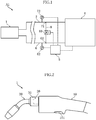
- Fig. 1 is a schematic configuration diagram showing an example of a welding torch cooling system according to the present disclosure.
- the welding torch cooling system A1 according to the present embodiment includes a welding torch 1, a cooling water circulator 4, a controller 5, a water feeding flow path 6, a water returning flow path 7 and a bypass flow path 8.
- the welding torch 1 according to the present embodiment is a water-cooled type torch and is internally formed with a flow path for flowing cooling water, which will be described later.
- the welding torch 1 is incorporated in an arc processing system and used for welding work such as consumable electrode arc welding.
- a welding wire may be supplied to the welding torch 1 by a wire feeding device using a power cable (both not shown). The welding wire is then fed toward a power supply chip provided in the tip of the welding torch 1 and then guided to the outside through the opening in the tip of the welding torch 1. Also, electric power is supplied from a power supply (not shown) to the welding torch 1 via the power cable, and the electric power is supplied to the welding wire via the power supply chip in the welding torch 1.
- the welding torch 1 illustrated in Fig. 2 is an example of configuration used for semi-automatic welding.
- the welding torch 1 includes a handle 10, a torch head 20 and a torch body 30.
- the handle 10 is a portion for an operator to grip and is cylindrical.
- the handle 10 has a base end (right side in Fig. 2 ) to which the above-described power cable is connected.
- the handle 10 is provided with switch 101 at an appropriate portion. To perform arc welding, the operator turns on the switch 101 while holding the handle 10. This causes welding current to be supplied to the welding wire inserted in the welding torch 1, allowing the welding wire to be fed toward a treatment object.
- the torch body 30 is removably connected to the torch head 20, which will be described later.
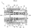
- the torch head 20 is provided at the tip of the handle 10 and cylindrical. As shown in fig. 3 , the torch head 20 has a first torch-head flow path 21, a second torch-head flow path 22, a first inlet/outlet 23, a second inlet/outlet 24, a movable part 25 and a biasing member 26.
- the first torch-head flow path 21 is a flow path for flowing the cooling water sent out from the cooling water circulator 4.
- the second torch-head flow path 22 is a flow path for flowing the cooling water that has passed through the torch body 30 described later.
- the first torch-head flow path 21 and the second torch-head flow paths 22 include a plurality of branch paths 211 and a plurality of branch paths 221, respectively, which extend in the axial direction of the torch head 20.
- the first inlet/outlet 23 and the second inlet/outlet 24 communicate with the first torch-head flow path 21 and the second torch-head flow path 22, respectively.
- the first inlet/outlet 23 and the second inlet/outlet 24 are formed at positions spaced apart from each other by a predetermined distance in the axial direction of the torch head 20.
- the second inlet/outlet 24 is closer to the tip of the torch head 20 than is the first inlet/outlet 23.
- the torch head 20 is formed with a cylindrical space 27 radially inward of the first and the second torch-head flow paths 21 and 22.
- the first inlet/outlet 23 and the second inlet/outlet 24 communicate with the cylindrical space 27 and each have an annular shape around the axis of the torch head 20.
- the movable part 25 is a cylindrical member and housed in the cylindrical space 27.
- the movable part 25 is movable in the axial direction of the torch head 20.
- the biasing member 26 is housed in the cylindrical space 27 and held in contact with the movable part 25.
- the biasing member 26 applies a biasing force in the axial direction of the torch head 20 (leftward in Fig. 3 ) and may be a compression spring, for example.
- Fig. 4 shows the state in which the torch body 30 is separated from the torch head 20.
- the movable part 25 is at a position displaced toward the tip of the torch head 20 (second position), closing the first inlet/outlet 23 and the second inlet/outlet 24.
- the torch head 20 is formed with a plurality of annular grooves 271 facing the cylindrical space 27 at appropriate positions, and an O-ring 272 is fitted in each of the annular grooves 271.
- the torch body 30 is cylindrical and may be made up of a plurality of cylindrical members joined together by appropriate means such as brazing, press fitting or screwing.
- the torch body 30 has a torch-body flow path 31, a first connection port 32 and a second connection port 33.
- the torch-body flow path 31 is a flow path for flowing cooling water in the torch body 30. Though detailed illustration is omitted, the torch-body flow path 31 extends from the base end (right end in Fig. 3 ) toward the tip (left side in the figure) of the torch body 30 and turns back in the middle to return to the base end. As shown in Fig. 6 , in the present embodiment, the torch-body flow path 31 is includes a plurality of branch paths 311 extending in the axial direction of the torch body 30.
- the torch body 30 has a base-end cylindrical part 34.
- the base-end cylindrical part 34 is a portion that may be fitted in the cylindrical space 27 of the torch head 20.
- the first connection port 32 communicates with an upstream end 31a of the torch-body flow path 31.
- the second connection port 33 communicates with a downstream end 31b of the torch-body flow path 31.
- the upstream end 31a and the downstream end 31b of the torch-body flow path 31 are formed in the base-end cylindrical part 34.
- the upstream end 31a and the downstream end 31b are located opposite to each other with respect to the central axis of the torch body 30.
- the first connection port 32 and the second connection port 33 are formed at positions spaced apart from each other by a predetermined distance in the axial direction of the torch body 30.
- the first connection port 32 and the second connection port 33 each open radially outward of the base-end cylindrical part 34.
- the first connection port 32 and the second connection port 33 each have an arcuate shape around the axis of the torch body 30.
- the first connection port 32 and the second connection port 33 are at positions corresponding to the first inlet/outlet 23 and the second inlet/outlet 24, respectively, in an axial direction.
- the distance between the first connection port 32 and the second connection port 33 in the above axial direction is substantially equal to the distance between the first inlet/outlet 23 and the second inlet/outlet 24 in the above axial direction.
- connection of the torch head 20 and the torch body 30 is performed using a union nut 35.
- the union nut 35 is loosely fitted to the outer periphery of the torch body 30 at a portion close to the base end.
- the female thread 351 of the union nut 35 is screwed onto the male thread 202 formed on the outer periphery of the torch head 20. In this way, the torch head 20 and the torch body 30 are connected to each other, as shown in Fig. 3 .
- the movable part 25 of the torch head 20 is at a position (first position) pushed deep into the torch head 20 by the tip of the torch body 30 against the biasing force of the biasing member 26.
- the movable part 25 is movable between the position shown in Fig. 3 (first position) and the position shown in Fig. 4 (second position).
- the first inlet/outlet 23 and the second inlet/outlet 24 of the torch head 20 communicate with the first connection port 32 and the second connection port 33 of the torch body 30, respectively.
- the cooling water sent out from the cooling water circulator 4 passes through the welding torch 1 by flowing in the first torch-head flow path 21, the torch-body flow path 31 and the second torch-head flow path 22 in the mentioned order.
- a cylindrical liner in which a welding wire (not shown) may be inserted is disposed in the through-hole 203 at the center of the torch head 20 and the through-hole 303 at the center of the torch body 30.
- the cooling water circulator 4 serves to circulate cooling water through the welding torch 1.
- the cooling water circulator 4 is provided with a tank, a pump and a cooler (all not shown) .
- the tank is a container for storing cooling water.
- the pump serves to force cooling water to flow toward the welding torch 1.
- the cooler serves to cool the cooling water returning from the welding torch 1 (the cooling water heated by passing through the welding torch 1) and may be a heat exchanger such as a radiator, for example.
- the water feeding flow path 6 is a flow path for feeding the cooling water pumped out of the cooling water circulator 4 to the welding torch 1.
- the water feeding flow path 6 has an upstream end connected to the cooling water circulator 4 and a downstream end connected to the first torch-head flow path 21 of the welding torch 1 (torch head 20).
- the water returning flow path 7 is a flow path for returning the cooling water flowing through the welding torch 1 to the cooling water circulator 4.
- the water returning flow path 7 has an upstream end connected to the second torch-head flow path 22 of the welding torch 1 (torch head 20) and a downstream end connected to the cooling water circulator 4.
- the bypass flow path 8 is a flow path for returning the cooling water pumped out of the cooling water circulator 4 to the cooling water circulator 4 without feeding to the welding torch 1.
- One end of the bypass flow path 8 is connected to a branching point 61 of the water feeding flow path 6, whereas the other end of the bypass flow path is connected to a merging point 71 of the water returning flow path 7.
- the bypass flow path 8 is provided with a valve 81 that is switchable between an open state and a closed state.
- the water feeding flow path 6, the water returning flow path 7, and the bypass flow path 8 described above may be provided by a pressure resistant hose.
- the water feeding flow path 6 is provided with a pressure measurer 62.
- the pressure measurer 62 is a pressure gauge for measuring the pressure inside the water feeding flow path 6 and located downstream from the branching point 61 of the water feeding flow path 6 (i.e., offset from the branching point 61 toward the welding torch 1).
- the water returning flow path 7 is also provided with a pressure measurer 72 (additional pressure measurer).
- the pressure measurer 72 is a pressure gauge for measuring the pressure inside the water returning flow path 7 and located upstream from the merging point 71 of the water returning flow path 7 (i.e., offset from the merging point 71 toward the welding torch 1).
- the controller 5 controls the operation of the cooling water circulator 4 or the valve 81 based on the measured values at the pressure measurers 62 and 72. Specifically, when the measured value at the pressure measurer 62 exceeds a first reference value, the controller 5 switches the valve 81 from the closed state to the open state to open the valve 81. Also, when the measured value at the pressure measurer 62 or the measured value at the pressure measurer 72 falls below a second reference value smaller than the first reference value, the controller 5 stops the operation of the cooling water circulator 4.
- the first inlet/outlet 23 and the second inlet/outlet 24 of the torch head 20 communicate with the first connection port 32 and the second connection port 33 of the torch body 30, respectively, as shown in Fig. 3 .
- This allows the cooling water pumped out of the cooling water circulator 4 to pass through the welding torch 1 by flowing in the first torch-head flow path 21, the torch-body flow path 31 and the second torch-head flow path 22 in the mentioned order.
- the first inlet/outlet 23 and the second inlet/outlet 24 of the torch head 20 are closed with the movable part 25, as shown in Fig. 4 .
- the torch head 20 and the torch body 30 are separated, water is stopped at the respective tips of the first torch-head flow path 21 and the second torch-head flow path 22 (the first inlet/outlet 23 and the second inlet/outlet 24), so that cooling water is prevented from leaking through the tip of the torch head 20. This enhances the efficiency of the work for replacing the torch body 30, for example.
- the first inlet/outlet 23 and the second inlet/outlet 24 of the torch head 20 are spaced apart from each other by a predetermined distance in the axial direction of the torch head 20 and each have an annular shape around the axis of the torch head.
- the first connection port 32 and the second connection port 33 of the torch body 30 are spaced apart from each other by the predetermined distance described above in the axial direction of the torch body 30 and each have an arcuate shape around the axis of the torch body.
- the first connection port 32 and the second connection port 33 are at positions corresponding to the first inlet/outlet 23 and the second inlet/outlet 24, respectively, in the axial direction.
- the first inlet/outlet 23 and the second inlet/outlet 24 communicate with the first connection port 32 and the second connection port 33, respectively, regardless of the relative position between the torch head 20 and the torch body 30 around the axial direction.
- the torch head 20 has a biasing member 26, and the biasing member 26 applies a biasing force to the movable part 25 while being in contact with the movable part 25.
- the movable part 25 is at a position (first position) pushed deep into the torch head 20 by the tip of the torch body 30 against the biasing force of the biasing member 26 when the torch head 20 and the torch body 30 are connected, while being at a position (second position) displaced toward the tip of the torch head 20 when the torch head 20 and the torch body 30 are separated.
- the valve 81 of the bypass flow path 8 is opened by the controller 5.
- the first inlet/outlet 23 and the second inlet/outlet 24 are closed, so that the pressure in the water feeding flow path 6 increases.
- the valve 81 is opened, causing the cooling water to circulate between the bypass flow path 8 and the cooling water circulator 4.
- the torch head 20 and the torch body 30 are connected, cooling water flows in the welding torch 1, so that the pressure in the water feeding flow path 6 reduces and the valve 81 is closed.
- the cooing water circulates between the welding torch 1 and the cooling water circulator 4.
- the system may be configured such that the controller 5 stops the operation of the cooling water circulator 4 when the measured value at the pressure measurer 62 exceeds the first reference value.
- the controller 5 stops the operation of the cooling water circulator 4 when the measured value at the pressure measurer 62 exceeds the first reference value.
- the pressure in the water feeding flow path 6 increases due to the closing of the first inlet/outlet 23 and the second inlet/outlet 24, so that the cooling water circulator 4 stops automatically.
- the controller 5 stops the operation of the cooling water circulator 4.
- the cooling water circulator 4 automatically stops if more than a predetermined amount of cooling water leaks from the water feeding flow path 6, the welding torch 1 or the water returning flow path 7.
- a welding torch comprising:
- a welding torch cooling system comprising:
- the welding torch cooling system further comprising an additional pressure measurer provided in the water returning flow path at a position upstream of the merging point, wherein the controller stops operation of the cooling water circulator when a measured value at the pressure measurer or a measured value at the additional pressure measurer falls below a second reference value that is smaller than the first reference value.
Landscapes
- Engineering & Computer Science (AREA)
- Physics & Mathematics (AREA)
- Mechanical Engineering (AREA)
- Plasma & Fusion (AREA)
- Optics & Photonics (AREA)
- Arc Welding In General (AREA)
- Gas Burners (AREA)
Abstract
Description
- The present disclosure relates to a welding torch and a welding torch cooling system.
- Automatic welding using a welding robot or a traveling carriage, or semi-automatic welding performed by an operator is employed in consumable electrode arc welding, for example. During the welding work in such automatic welding, for example, a welding wire is fed from a wire feeder to a welding torch, and electric power is supplied to the welding torch.
- A water-cooled type welding torch is known as a welding torch used for such welding work. In a water-cooled type welding torch, cooling water supplied from a cooling water circulator circulates through the welding torch. A welding torch used for semi-automatic welding may typically include a torch head, to which a torch body is connected. In a water-cooled type welding torch, the power cable extending to the welding torch is cooled, and also, the torch head, which the operator holds with a hand, or the torch body, in which a power supply chip is mounted, are prevented from being excessively heated.
- In such a water-cooled type welding torch, the maintenance work such as replacing a consumable part in a tip of a torch involves stopping the operation of the cooling water circulator and separating the torch body from the torch head. At this time, water may adhere to the welding wire if the cooling water remaining in the cooling water flow path leaks from the connection between the torch body and the torch head. Also, when the torch body is separated without turning off the stop switch of the cooling water circulator by mistake, cooling water spouts from the tip of the torch head to adhere to the welding wire. Water adhesion to the welding wire causes a welding failure.
- An object of the present disclosure is to provide a more suitable welding torch. For example, an object of the present disclosure is to provide a welding torch suitable for improving the efficiency of the work for replacing a torch body in a water-cooled type welding torch, for example,
- According to a first aspect of the present disclosure, a welding torch is provided. The welding torch includes a torch head and a torch body removably connected to the torch head. The torch head includes a first torch-head flow path and a second torch-head flow path for flowing cooling water, a first inlet/outlet and a second inlet/outlet communicating with the first torch-head flow path and the second torch-head flow path, respectively, and a movable part that is movable in an axial direction of the torch head. The torch body includes a torch-body flow path for flowing cooling water, and a first connection port and a second connection port communicating with opposite ends of the torch-body flow path, respectively. The first inlet/outlet and the second inlet/outlet communicate with the first connection port and the second connection port, respectively, when the torch head and the torch body are connected to each other. The first inlet/outlet and the second inlet/outlet are closed with the movable part when the torch head and the torch body are separated.
- According to a second aspect of the present disclosure, there is provided a welding torch cooling system. The welding torch cooling system includes a welding torch according to the first aspect of the present disclosure, a cooling water circulator, a water feeding flow path, a water returning flow path, a bypass flow path, a valve, a pressure measurer, and a controller. The cooling water circulator circulates cooling water through the welding torch. The water feeding flow path has an upstream end connected to the cooling water circulator and a downstream end connected to the first torch-head flow path. The water returning flow path has an upstream end connected to the second torch-head flow path and a downstream end connected to the cooling water circulator. The bypass flow path has a first end and a second end. The first end is connected to a branching point of the water feeding flow path, and the second end is connected to a merging point of the water returning flow path. The valve is provided in the bypass flow path and switchable between an on open state and a closed state. The pressure measurer is provided in the water feeding flow path at a position downstream of the branching point. The controller controls operation of at least one of the cooling water circulator and the valve based on a measured value at the pressure measurer.
- Other features and advantages of the present disclosure will become apparent from the detailed description given below with reference to the accompanying drawings.
-
-
Fig. 1 is a schematic configuration diagram showing an example of a welding torch cooling system according to the present disclosure; -
Fig. 2 is a front view showing an example of a welding torch according to the present disclosure; -
Fig. 3 is an enlarged longitudinal sectional view of a part of the welding torch shown inFig. 2 ; -
Fig. 4 is a sectional view corresponding toFig. 3 , showing the state in which a torch body is separated from a torch head; -
Fig. 5 is a sectional view taken along line V-V inFig. 3 ; and -
Fig. 6 is a sectional view taken along line VI-VI inFig. 3 . - Preferred embodiments of the present disclosure are described below with reference to the accompanying drawings.
-
Fig. 1 is a schematic configuration diagram showing an example of a welding torch cooling system according to the present disclosure. The welding torch cooling system A1 according to the present embodiment includes awelding torch 1, acooling water circulator 4, a controller 5, a waterfeeding flow path 6, a water returningflow path 7 and abypass flow path 8. Thewelding torch 1 according to the present embodiment is a water-cooled type torch and is internally formed with a flow path for flowing cooling water, which will be described later. - The
welding torch 1 is incorporated in an arc processing system and used for welding work such as consumable electrode arc welding. In the arc processing system, a welding wire may be supplied to thewelding torch 1 by a wire feeding device using a power cable (both not shown). The welding wire is then fed toward a power supply chip provided in the tip of thewelding torch 1 and then guided to the outside through the opening in the tip of thewelding torch 1. Also, electric power is supplied from a power supply (not shown) to thewelding torch 1 via the power cable, and the electric power is supplied to the welding wire via the power supply chip in thewelding torch 1. - The
welding torch 1 illustrated inFig. 2 is an example of configuration used for semi-automatic welding. Thewelding torch 1 includes ahandle 10, atorch head 20 and atorch body 30. Thehandle 10 is a portion for an operator to grip and is cylindrical. Thehandle 10 has a base end (right side inFig. 2 ) to which the above-described power cable is connected. Thehandle 10 is provided withswitch 101 at an appropriate portion. To perform arc welding, the operator turns on theswitch 101 while holding thehandle 10. This causes welding current to be supplied to the welding wire inserted in thewelding torch 1, allowing the welding wire to be fed toward a treatment object. Thetorch body 30 is removably connected to thetorch head 20, which will be described later. - The
torch head 20 is provided at the tip of thehandle 10 and cylindrical. As shown infig. 3 , thetorch head 20 has a first torch-head flow path 21, a second torch-head flow path 22, a first inlet/outlet 23, a second inlet/outlet 24, amovable part 25 and abiasing member 26. - The first torch-
head flow path 21 is a flow path for flowing the cooling water sent out from thecooling water circulator 4. The second torch-head flow path 22 is a flow path for flowing the cooling water that has passed through thetorch body 30 described later. As shown inFigs. 5 and 6 , in the present embodiment, the first torch-head flow path 21 and the second torch-head flow paths 22 include a plurality ofbranch paths 211 and a plurality ofbranch paths 221, respectively, which extend in the axial direction of thetorch head 20. - The first inlet/
outlet 23 and the second inlet/outlet 24 communicate with the first torch-head flow path 21 and the second torch-head flow path 22, respectively. The first inlet/outlet 23 and the second inlet/outlet 24 are formed at positions spaced apart from each other by a predetermined distance in the axial direction of thetorch head 20. The second inlet/outlet 24 is closer to the tip of thetorch head 20 than is the first inlet/outlet 23. Thetorch head 20 is formed with acylindrical space 27 radially inward of the first and the second torch-head flow paths outlet 23 and the second inlet/outlet 24 communicate with thecylindrical space 27 and each have an annular shape around the axis of thetorch head 20. - The
movable part 25 is a cylindrical member and housed in thecylindrical space 27. Themovable part 25 is movable in the axial direction of thetorch head 20. The biasingmember 26 is housed in thecylindrical space 27 and held in contact with themovable part 25. The biasingmember 26 applies a biasing force in the axial direction of the torch head 20 (leftward inFig. 3 ) and may be a compression spring, for example. -
Fig. 4 shows the state in which thetorch body 30 is separated from thetorch head 20. In this state, themovable part 25 is at a position displaced toward the tip of the torch head 20 (second position), closing the first inlet/outlet 23 and the second inlet/outlet 24. Thetorch head 20 is formed with a plurality ofannular grooves 271 facing thecylindrical space 27 at appropriate positions, and an O-ring 272 is fitted in each of theannular grooves 271. With such an arrangement, when thetorch head 20 and thetorch body 30 are separated, water is stopped at the respective tips of the first torch-head flow path 21 and the second torch-head flow path 22 (the first inlet/outlet 23 and the second inlet/outlet 24), so that cooling water is prevented from leaking through the tip of thetorch head 20. In the state shown inFig. 4 , anengagement target part 251 formed at themovable part 25 is engaged by anengagement part 201 formed in the torch, so that movement of themovable part 25 toward the tip of the torch head 20 (leftward in the figure) is prevented. - The
torch body 30 is cylindrical and may be made up of a plurality of cylindrical members joined together by appropriate means such as brazing, press fitting or screwing. Thetorch body 30 has a torch-body flow path 31, afirst connection port 32 and asecond connection port 33. - The torch-
body flow path 31 is a flow path for flowing cooling water in thetorch body 30. Though detailed illustration is omitted, the torch-body flow path 31 extends from the base end (right end inFig. 3 ) toward the tip (left side in the figure) of thetorch body 30 and turns back in the middle to return to the base end. As shown inFig. 6 , in the present embodiment, the torch-body flow path 31 is includes a plurality ofbranch paths 311 extending in the axial direction of thetorch body 30. - In the present embodiment, the
torch body 30 has a base-endcylindrical part 34. The base-endcylindrical part 34 is a portion that may be fitted in thecylindrical space 27 of thetorch head 20. - The
first connection port 32 communicates with anupstream end 31a of the torch-body flow path 31. Thesecond connection port 33 communicates with adownstream end 31b of the torch-body flow path 31. Theupstream end 31a and thedownstream end 31b of the torch-body flow path 31 are formed in the base-endcylindrical part 34. Theupstream end 31a and thedownstream end 31b are located opposite to each other with respect to the central axis of thetorch body 30. Thefirst connection port 32 and thesecond connection port 33 are formed at positions spaced apart from each other by a predetermined distance in the axial direction of thetorch body 30. Thefirst connection port 32 and thesecond connection port 33 each open radially outward of the base-endcylindrical part 34. Thefirst connection port 32 and thesecond connection port 33 each have an arcuate shape around the axis of thetorch body 30. - The
first connection port 32 and thesecond connection port 33 are at positions corresponding to the first inlet/outlet 23 and the second inlet/outlet 24, respectively, in an axial direction. The distance between thefirst connection port 32 and thesecond connection port 33 in the above axial direction is substantially equal to the distance between the first inlet/outlet 23 and the second inlet/outlet 24 in the above axial direction. - In the present embodiment, connection of the
torch head 20 and thetorch body 30 is performed using aunion nut 35. Theunion nut 35 is loosely fitted to the outer periphery of thetorch body 30 at a portion close to the base end. To connect thetorch body 30 to thetorch head 20, thefemale thread 351 of theunion nut 35 is screwed onto themale thread 202 formed on the outer periphery of thetorch head 20. In this way, thetorch head 20 and thetorch body 30 are connected to each other, as shown inFig. 3 . - In the state in which the
torch body 30 is connected to thetorch head 20, themovable part 25 of thetorch head 20 is at a position (first position) pushed deep into thetorch head 20 by the tip of thetorch body 30 against the biasing force of the biasingmember 26. Themovable part 25 is movable between the position shown inFig. 3 (first position) and the position shown inFig. 4 (second position). - Also, as shown in
Fig. 3 , when thetorch head 20 and thetorch body 30 are connected to each other, the first inlet/outlet 23 and the second inlet/outlet 24 of thetorch head 20 communicate with thefirst connection port 32 and thesecond connection port 33 of thetorch body 30, respectively. Thus, when thetorch head 20 and thetorch body 30 are connected, the cooling water sent out from the coolingwater circulator 4 passes through thewelding torch 1 by flowing in the first torch-head flow path 21, the torch-body flow path 31 and the second torch-head flow path 22 in the mentioned order. - Note that a cylindrical liner (not shown) in which a welding wire (not shown) may be inserted is disposed in the through-
hole 203 at the center of thetorch head 20 and the through-hole 303 at the center of thetorch body 30. - Returning to
Fig. 1 , the coolingwater circulator 4 serves to circulate cooling water through thewelding torch 1. The coolingwater circulator 4 is provided with a tank, a pump and a cooler (all not shown) . The tank is a container for storing cooling water. The pump serves to force cooling water to flow toward thewelding torch 1. The cooler serves to cool the cooling water returning from the welding torch 1 (the cooling water heated by passing through the welding torch 1) and may be a heat exchanger such as a radiator, for example. - The water
feeding flow path 6 is a flow path for feeding the cooling water pumped out of the coolingwater circulator 4 to thewelding torch 1. The waterfeeding flow path 6 has an upstream end connected to thecooling water circulator 4 and a downstream end connected to the first torch-head flow path 21 of the welding torch 1 (torch head 20). - The water returning
flow path 7 is a flow path for returning the cooling water flowing through thewelding torch 1 to thecooling water circulator 4. The water returningflow path 7 has an upstream end connected to the second torch-head flow path 22 of the welding torch 1 (torch head 20) and a downstream end connected to thecooling water circulator 4. - The
bypass flow path 8 is a flow path for returning the cooling water pumped out of the coolingwater circulator 4 to thecooling water circulator 4 without feeding to thewelding torch 1. One end of thebypass flow path 8 is connected to a branchingpoint 61 of the waterfeeding flow path 6, whereas the other end of the bypass flow path is connected to amerging point 71 of the water returningflow path 7. Thebypass flow path 8 is provided with avalve 81 that is switchable between an open state and a closed state. The waterfeeding flow path 6, the water returningflow path 7, and thebypass flow path 8 described above may be provided by a pressure resistant hose. - In the present embodiment, the water
feeding flow path 6 is provided with apressure measurer 62. Thepressure measurer 62 is a pressure gauge for measuring the pressure inside the waterfeeding flow path 6 and located downstream from the branchingpoint 61 of the water feeding flow path 6 (i.e., offset from the branchingpoint 61 toward the welding torch 1). - In the present embodiment, the water returning
flow path 7 is also provided with a pressure measurer 72 (additional pressure measurer). Thepressure measurer 72 is a pressure gauge for measuring the pressure inside the water returningflow path 7 and located upstream from the mergingpoint 71 of the water returning flow path 7 (i.e., offset from the mergingpoint 71 toward the welding torch 1). - The controller 5 controls the operation of the cooling
water circulator 4 or thevalve 81 based on the measured values at thepressure measurers pressure measurer 62 exceeds a first reference value, the controller 5 switches thevalve 81 from the closed state to the open state to open thevalve 81. Also, when the measured value at thepressure measurer 62 or the measured value at thepressure measurer 72 falls below a second reference value smaller than the first reference value, the controller 5 stops the operation of the coolingwater circulator 4. - In the
welding torch 1 according to the present embodiment, when thetorch head 20 and thetorch body 30 are connected to each other, the first inlet/outlet 23 and the second inlet/outlet 24 of thetorch head 20 communicate with thefirst connection port 32 and thesecond connection port 33 of thetorch body 30, respectively, as shown inFig. 3 . This allows the cooling water pumped out of the coolingwater circulator 4 to pass through thewelding torch 1 by flowing in the first torch-head flow path 21, the torch-body flow path 31 and the second torch-head flow path 22 in the mentioned order. - On the other hand, when the
torch head 20 and thetorch body 30 are separated from each other, the first inlet/outlet 23 and the second inlet/outlet 24 of thetorch head 20 are closed with themovable part 25, as shown inFig. 4 . With such an arrangement, when thetorch head 20 and thetorch body 30 are separated, water is stopped at the respective tips of the first torch-head flow path 21 and the second torch-head flow path 22 (the first inlet/outlet 23 and the second inlet/outlet 24), so that cooling water is prevented from leaking through the tip of thetorch head 20. This enhances the efficiency of the work for replacing thetorch body 30, for example. - The first inlet/
outlet 23 and the second inlet/outlet 24 of thetorch head 20 are spaced apart from each other by a predetermined distance in the axial direction of thetorch head 20 and each have an annular shape around the axis of the torch head. Thefirst connection port 32 and thesecond connection port 33 of thetorch body 30 are spaced apart from each other by the predetermined distance described above in the axial direction of thetorch body 30 and each have an arcuate shape around the axis of the torch body. With such a configuration, thefirst connection port 32 and thesecond connection port 33 are at positions corresponding to the first inlet/outlet 23 and the second inlet/outlet 24, respectively, in the axial direction. Thus, when thetorch head 20 and thetorch body 30 are connected, the first inlet/outlet 23 and the second inlet/outlet 24 communicate with thefirst connection port 32 and thesecond connection port 33, respectively, regardless of the relative position between thetorch head 20 and thetorch body 30 around the axial direction. - In the present embodiment, the
torch head 20 has a biasingmember 26, and the biasingmember 26 applies a biasing force to themovable part 25 while being in contact with themovable part 25. Themovable part 25 is at a position (first position) pushed deep into thetorch head 20 by the tip of thetorch body 30 against the biasing force of the biasingmember 26 when thetorch head 20 and thetorch body 30 are connected, while being at a position (second position) displaced toward the tip of thetorch head 20 when thetorch head 20 and thetorch body 30 are separated. With such a configuration, when thetorch body 30 is separated from thetorch head 20, the first inlet/outlet 23 and the second inlet/outlet 24 are properly closed with themovable part 25. Thus, improved water stopping performance at the tip of thetorch head 20 when thetorch head 20 and thetorch body 30 are separated is reliably achieved. - In the welding torch cooling system A1 of the present embodiment, when the measured value at the
pressure measurer 62 provided in the waterfeeding flow path 6 exceeds the first reference value, thevalve 81 of thebypass flow path 8 is opened by the controller 5. When thetorch body 30 is separated from thetorch head 20, the first inlet/outlet 23 and the second inlet/outlet 24 are closed, so that the pressure in the waterfeeding flow path 6 increases. When the pressure in the waterfeeding flow path 6 exceeds a predetermined value, thevalve 81 is opened, causing the cooling water to circulate between thebypass flow path 8 and the coolingwater circulator 4. When thetorch head 20 and thetorch body 30 are connected, cooling water flows in thewelding torch 1, so that the pressure in the waterfeeding flow path 6 reduces and thevalve 81 is closed. Thus, the cooing water circulates between thewelding torch 1 and the coolingwater circulator 4. - With such a configuration, when the
torch head 20 and thetorch body 30 are separated, leakage of cooling water from the welding torch 1 (torch head 20) is avoided, and the flow path of the cooling water is automatically switched to thebypass flow path 8. Thus, the work for replacing thetorch body 30, for example, can be performed without the need for on-off switching the coolingwater circulator 4, which leads to improved work efficiency. - Note that, unlike the present embodiment, the system may be configured such that the controller 5 stops the operation of the cooling
water circulator 4 when the measured value at thepressure measurer 62 exceeds the first reference value. In this case, when thetorch body 30 is separated from thetorch head 20, the pressure in the waterfeeding flow path 6 increases due to the closing of the first inlet/outlet 23 and the second inlet/outlet 24, so that the coolingwater circulator 4 stops automatically. - In the present embodiment, when the measured value at the
pressure measurer 62 provided in the waterfeeding flow path 6 or the measured value at thepressure measurer 72 provided in the water returningflow path 7 falls below the second reference value (the second reference value < the first reference value), the controller 5 stops the operation of the coolingwater circulator 4. With such a configuration, when cooling water circulates between thewelding torch 1 and the coolingwater circulator 4, the coolingwater circulator 4 automatically stops if more than a predetermined amount of cooling water leaks from the waterfeeding flow path 6, thewelding torch 1 or the water returningflow path 7. Thus, excessive leakage of the cooling water is prevented, so that a failure due to insufficient cooling of thewelding torch 1 is avoided in advance. - Though the embodiments of the present disclosure are described, the scope of the present disclosure is not limited to the foregoing embodiments.
- The present disclosure includes embodiments according to the following clauses:
- A welding torch comprising:
- a torch head; and
- a torch body removably connected to the torch head, wherein:
the torch head includes a first torch-head flow path and a second torch-head flow path for flowing cooling water, a first inlet/outlet and a second inlet/outlet communicating with the first torch-head flow path and the second torch-head flow path, respectively, and a movable part that is movable in an axial direction of the torch head, - the torch body includes a torch-body flow path for flowing cooling water, and a first connection port and a second connection port communicating with opposite ends of the torch-body flow path, respectively,
- the first inlet/outlet and the second inlet/outlet communicate with the first connection port and the second connection port, respectively, when the torch head and the torch body are connected to each other, and
- the first inlet/outlet and the second inlet/outlet are closed with the movable part when the torch head and the torch body are separated.
- The welding torch according to
clause 1, wherein: - the first inlet/outlet and the second inlet/outlet are spaced apart from each other by a predetermined distance in the axial direction of the torch head, each of the first inlet/outlet and the second inlet/outlet having an annular shape around the axis of the torch head, and
- the first connection port and the second connection port are spaced apart from each other by the predetermined distance in an axial direction of the torch body, each of the first connection port and the second connection port having an arcuate shape around the axis of the torch body.
- The welding torch according to
clause 1 or 2, wherein: - the torch head has a biasing member that applies a biasing force to the movable part in the axial direction of the torch head while being in contact with the movable part,
- the movable part is movable between a first position and a second position,
- at the first position of the movable part, the movable part is pushed deep into the torch head by a tip of the torch body against a biasing force of the biasing member when the torch head and the torch body are connected, and
- at the second position of the movable part, the movable part is displaced toward the tip of the torch head by the biasing force of the biasing member when the torch head and the torch body are separated.
- A welding torch cooling system comprising:
- a welding torch as set forth in any of the clauses 1-3;
- a cooling water circulator for circulating cooling water through the welding torch;
- a water feeding flow path having an upstream end connected to the cooling water circulator and a downstream end connected to the first torch-head flow path;
- a water returning flow path having an upstream end connected to the second torch-head flow path and a downstream end connected to the cooling water circulator;
- a bypass flow path having a first end and a second end, the first end being connected to a branching point of the water feeding flow path while the second end being connected to a merging point of the water returning flow path;
- a valve provided in the bypass flow path, the valve being switchable between an on open state and a closed state;
- a pressure measurer provided in the water feeding flow path at a position downstream of the branching point; and
- a controller that controls operation of at least one of the cooling water circulator and the valve based on a measured value at the pressure measurer.
- The welding torch cooling system according to
clause 4, wherein the controller opens the valve when the measured value at the pressure measurer exceeds a first reference value. - The welding torch cooling system according to clause 5, further comprising an additional pressure measurer provided in the water returning flow path at a position upstream of the merging point,
wherein the controller stops operation of the cooling water circulator when a measured value at the pressure measurer or a measured value at the additional pressure measurer falls below a second reference value that is smaller than the first reference value.
Claims (6)
- A welding torch comprising:a torch head; anda torch body removably connected to the torch head, wherein:the torch head includes a first torch-head flow path and a second torch-head flow path for flowing cooling water, a first inlet/outlet and a second inlet/outlet communicating with the first torch-head flow path and the second torch-head flow path, respectively, and a movable part that is movable in an axial direction of the torch head,the torch body includes a torch-body flow path for flowing cooling water, and a first connection port and a second connection port communicating with opposite ends of the torch-body flow path, respectively,the first inlet/outlet and the second inlet/outlet communicate with the first connection port and the second connection port, respectively, when the torch head and the torch body are connected to each other, andthe first inlet/outlet and the second inlet/outlet are closed with the movable part when the torch head and the torch body are separated.
- The welding torch according to claim 1, wherein:the first inlet/outlet and the second inlet/outlet are spaced apart from each other by a predetermined distance in the axial direction of the torch head, each of the first inlet/outlet and the second inlet/outlet having an annular shape around the axis of the torch head, andthe first connection port and the second connection port are spaced apart from each other by the predetermined distance in an axial direction of the torch body, each of the first connection port and the second connection port having an arcuate shape around the axis of the torch body.
- The welding torch according to claim 1 or 2, wherein:the torch head comprises a biasing member that applies a biasing force to the movable part in the axial direction of the torch head while being in contact with the movable part,the movable part is movable between a first position and a second position,at the first position of the movable part, the movable part is pushed deep into the torch head by a tip of the torch body against a biasing force of the biasing member when the torch head and the torch body are connected, andat the second position of the movable part, the movable part is displaced toward the tip of the torch head by the biasing force of the biasing member when the torch head and the torch body are separated.
- A welding torch cooling system comprising:a welding torch as set forth in any of claims 1-3;a cooling water circulator for circulating cooling water through the welding torch;a water feeding flow path having an upstream end connected to the cooling water circulator and a downstream end connected to the first torch-head flow path;a water returning flow path having an upstream end connected to the second torch-head flow path and a downstream end connected to the cooling water circulator;a bypass flow path having a first end and a second end, the first end being connected to a branching point of the water feeding flow path while the second end being connected to a merging point of the water returning flow path;a valve provided in the bypass flow path, the valve being switchable between an on open state and a closed state;a pressure measurer provided in the water feeding flow path at a position downstream of the branching point; anda controller that controls operation of at least one of the cooling water circulator and the valve based on a measured value at the pressure measurer.
- The welding torch cooling system according to claim 4, wherein the controller opens the valve when the measured value at the pressure measurer exceeds a first reference value.
- The welding torch cooling system according to claim 5, further comprising an additional pressure measurer provided in the water returning flow path at a position upstream of the merging point,
wherein the controller stops operation of the cooling water circulator when a measured value at the pressure measurer or a measured value at the additional pressure measurer falls below a second reference value that is smaller than the first reference value.
Applications Claiming Priority (2)
| Application Number | Priority Date | Filing Date | Title |
|---|---|---|---|
| JP2017117844A JP6923266B2 (en) | 2017-06-15 | 2017-06-15 | Welding torch cooling system |
| PCT/JP2018/018162 WO2018230209A1 (en) | 2017-06-15 | 2018-05-10 | Welding torch and welding torch cooling system |
Publications (3)
| Publication Number | Publication Date |
|---|---|
| EP3639960A1 true EP3639960A1 (en) | 2020-04-22 |
| EP3639960A4 EP3639960A4 (en) | 2021-03-24 |
| EP3639960B1 EP3639960B1 (en) | 2024-07-03 |
Family
ID=64659654
Family Applications (1)
| Application Number | Title | Priority Date | Filing Date |
|---|---|---|---|
| EP18816970.0A Active EP3639960B1 (en) | 2017-06-15 | 2018-05-10 | Welding torch and welding torch cooling system |
Country Status (6)
| Country | Link |
|---|---|
| US (1) | US11370053B2 (en) |
| EP (1) | EP3639960B1 (en) |
| JP (1) | JP6923266B2 (en) |
| CN (1) | CN110809503A (en) |
| FI (1) | FI3639960T3 (en) |
| WO (1) | WO2018230209A1 (en) |
Families Citing this family (2)
| Publication number | Priority date | Publication date | Assignee | Title |
|---|---|---|---|---|
| CN116087760A (en) * | 2021-11-05 | 2023-05-09 | 华晨宝马汽车有限公司 | Improved welding gun test equipment and method |
| CN118081237B (en) * | 2024-04-28 | 2024-07-05 | 上海众冠智能设备有限公司 | Welding robot with cooling system |
Family Cites Families (13)
| Publication number | Priority date | Publication date | Assignee | Title |
|---|---|---|---|---|
| BE788809A (en) * | 1971-09-16 | 1973-01-02 | Messer Griesheim Gmbh | WELDING TORCH |
| DE2243924A1 (en) * | 1972-09-07 | 1974-03-21 | Messer Griesheim Gmbh | Gas shielded electric arc welding gun - is simply adaptable and manipulatable |
| JPS5768279A (en) | 1980-10-13 | 1982-04-26 | Matsushita Electric Ind Co Ltd | Welding torch |
| US4508951A (en) * | 1982-08-19 | 1985-04-02 | Richard B. Rehrig | Fluid baffle assembly for a water-cooled welding torch |
| US4582979A (en) * | 1984-09-10 | 1986-04-15 | Moerke Delford A | Arc welding system and docking assembly therefor |
| US5378868A (en) * | 1992-03-17 | 1995-01-03 | Burkhardt; James F. | Shut off check valve for a welding gun |
| DE4229227C1 (en) * | 1992-09-02 | 1993-09-02 | Alexander Binzel Gmbh & Co Kg, 6300 Giessen, De | Water-cooled inert gas welding torch with cooling circulation - has water supply and return hoses coupled to torch body, water supply and return channels through torch stem to nozzle and by=pass with valve connecting supply and return |
| JP3314621B2 (en) | 1995-07-31 | 2002-08-12 | 松下電器産業株式会社 | Welding device and its cooling water device |
| JP3882368B2 (en) | 1998-10-30 | 2007-02-14 | 松下電器産業株式会社 | Welding torch |
| JP2009269049A (en) | 2008-05-07 | 2009-11-19 | Daihen Corp | Welding torch |
| AT512725B1 (en) * | 2012-03-30 | 2014-02-15 | Fronius Int Gmbh | Plug part and socket part for releasably connecting a pipe bend of a water-cooled welding torch with a hose package and connecting device with such a plug part and socket part |
| CN103009495A (en) | 2012-11-19 | 2013-04-03 | 固铂成山(山东)轮胎有限公司 | Control, detection and alarming device for circulating water system for internal mixer |
| CN205822349U (en) | 2016-05-27 | 2016-12-21 | 中交第一航务工程局有限公司 | A kind of water tower-constant voltage duplex water system |
-
2017
- 2017-06-15 JP JP2017117844A patent/JP6923266B2/en active Active
-
2018
- 2018-05-10 CN CN201880039145.9A patent/CN110809503A/en active Pending
- 2018-05-10 EP EP18816970.0A patent/EP3639960B1/en active Active
- 2018-05-10 FI FIEP18816970.0T patent/FI3639960T3/en active
- 2018-05-10 WO PCT/JP2018/018162 patent/WO2018230209A1/en not_active Ceased
- 2018-05-10 US US16/620,259 patent/US11370053B2/en active Active
Also Published As
| Publication number | Publication date |
|---|---|
| US11370053B2 (en) | 2022-06-28 |
| WO2018230209A1 (en) | 2018-12-20 |
| JP2019000876A (en) | 2019-01-10 |
| FI3639960T3 (en) | 2024-10-02 |
| EP3639960A4 (en) | 2021-03-24 |
| EP3639960B1 (en) | 2024-07-03 |
| JP6923266B2 (en) | 2021-08-18 |
| US20200094344A1 (en) | 2020-03-26 |
| CN110809503A (en) | 2020-02-18 |
Similar Documents
| Publication | Publication Date | Title |
|---|---|---|
| CA2535077C (en) | Torch for arc welding gun | |
| US4864099A (en) | Water cooled semi-automatic welding gun | |
| CN102596480B (en) | For hose and the coupling arrangement of welder | |
| US11752568B2 (en) | Fluid transfer of suction force between drawback apparatuses | |
| US11370053B2 (en) | Welding torch and welding torch cooling system | |
| TWI420978B (en) | Retract start plasma torch with reversible coolant flow | |
| US11590597B2 (en) | Systems, methods, and apparatus to preheat welding wire | |
| EP2953759B1 (en) | System and method for thermally working a workpiece using either a plasma torch or an oxy-fuel torch to be exchangeably mounted on one torch receptacle | |
| JP5240892B2 (en) | Cooling water stop device for electric resistance spot welding machine, and electric resistance spot welding machine provided with the same | |
| US20100258534A1 (en) | Method of converting a gas tungsten arc welding system to a plasma welding system | |
| WO2010005368A1 (en) | Cooling device for welding device | |
| CA3066619C (en) | Welding torch with a first contact tip to preheat welding wire and a second contact tip | |
| US7857173B2 (en) | Solenoid control valve with quick-connect fittings for mating with an adhesive control module assembly of a hot melt adhesive dispensing system | |
| US3108179A (en) | Buffer gas welding installation | |
| EP3634682A1 (en) | Contact tips with screw threads and head to enable unthreading or the screw threads comprising longitudinal slots for gas flow; welding torch with contact tips | |
| CN110505935A (en) | Tig torch main body, tig torch handle and the tig torch with this tig torch main body and tig torch handle | |
| CN111315524A (en) | Welding torch with two contacts and multiple liquid-cooled components for conducting current to the contacts | |
| US10888946B2 (en) | TIG gun power pin for welding device or system and multi-process welder with a single gas flow path | |
| KR20150006676A (en) | Cooling structure of spot welding device | |
| US20260025903A1 (en) | Apparatus and methods for purging cooling liquid conduits in a plasma arc torch | |
| JP3160682U (en) | Water stop device for spot welder | |
| KR20230153957A (en) | Welding machine | |
| WO2020165700A1 (en) | Welding torch | |
| JP2021109216A (en) | Resistance welder |
Legal Events
| Date | Code | Title | Description |
|---|---|---|---|
| STAA | Information on the status of an ep patent application or granted ep patent |
Free format text: STATUS: THE INTERNATIONAL PUBLICATION HAS BEEN MADE |
|
| PUAI | Public reference made under article 153(3) epc to a published international application that has entered the european phase |
Free format text: ORIGINAL CODE: 0009012 |
|
| STAA | Information on the status of an ep patent application or granted ep patent |
Free format text: STATUS: REQUEST FOR EXAMINATION WAS MADE |
|
| 17P | Request for examination filed |
Effective date: 20191205 |
|
| AK | Designated contracting states |
Kind code of ref document: A1 Designated state(s): AL AT BE BG CH CY CZ DE DK EE ES FI FR GB GR HR HU IE IS IT LI LT LU LV MC MK MT NL NO PL PT RO RS SE SI SK SM TR |
|
| AX | Request for extension of the european patent |
Extension state: BA ME |
|
| DAV | Request for validation of the european patent (deleted) | ||
| DAX | Request for extension of the european patent (deleted) | ||
| RAP1 | Party data changed (applicant data changed or rights of an application transferred) |
Owner name: DAIHEN CORPORATION |
|
| A4 | Supplementary search report drawn up and despatched |
Effective date: 20210224 |
|
| RIC1 | Information provided on ipc code assigned before grant |
Ipc: B23K 37/00 20060101ALI20210218BHEP Ipc: B23K 9/28 20060101ALI20210218BHEP Ipc: B23K 9/29 20060101AFI20210218BHEP Ipc: B23K 9/32 20060101ALI20210218BHEP |
|
| STAA | Information on the status of an ep patent application or granted ep patent |
Free format text: STATUS: EXAMINATION IS IN PROGRESS |
|
| 17Q | First examination report despatched |
Effective date: 20221214 |
|
| GRAP | Despatch of communication of intention to grant a patent |
Free format text: ORIGINAL CODE: EPIDOSNIGR1 |
|
| STAA | Information on the status of an ep patent application or granted ep patent |
Free format text: STATUS: GRANT OF PATENT IS INTENDED |
|
| INTG | Intention to grant announced |
Effective date: 20231219 |
|
| RIN1 | Information on inventor provided before grant (corrected) |
Inventor name: FUKUNAGA, YOSHIAKI Inventor name: MORITA, YUKIYA Inventor name: MINAMOTO, TETSUSHI |
|
| GRAS | Grant fee paid |
Free format text: ORIGINAL CODE: EPIDOSNIGR3 |
|
| GRAA | (expected) grant |
Free format text: ORIGINAL CODE: 0009210 |
|
| STAA | Information on the status of an ep patent application or granted ep patent |
Free format text: STATUS: THE PATENT HAS BEEN GRANTED |
|
| AK | Designated contracting states |
Kind code of ref document: B1 Designated state(s): AL AT BE BG CH CY CZ DE DK EE ES FI FR GB GR HR HU IE IS IT LI LT LU LV MC MK MT NL NO PL PT RO RS SE SI SK SM TR |
|
| REG | Reference to a national code |
Ref country code: CH Ref legal event code: EP |
|
| REG | Reference to a national code |
Ref country code: DE Ref legal event code: R096 Ref document number: 602018071370 Country of ref document: DE |
|
| REG | Reference to a national code |
Ref country code: FI Ref legal event code: FGE |
|
| REG | Reference to a national code |
Ref country code: LT Ref legal event code: MG9D |
|
| REG | Reference to a national code |
Ref country code: NL Ref legal event code: MP Effective date: 20240703 |
|
| PG25 | Lapsed in a contracting state [announced via postgrant information from national office to epo] |
Ref country code: PT Free format text: LAPSE BECAUSE OF FAILURE TO SUBMIT A TRANSLATION OF THE DESCRIPTION OR TO PAY THE FEE WITHIN THE PRESCRIBED TIME-LIMIT Effective date: 20241104 |
|
| PG25 | Lapsed in a contracting state [announced via postgrant information from national office to epo] |
Ref country code: NL Free format text: LAPSE BECAUSE OF FAILURE TO SUBMIT A TRANSLATION OF THE DESCRIPTION OR TO PAY THE FEE WITHIN THE PRESCRIBED TIME-LIMIT Effective date: 20240703 |
|
| PG25 | Lapsed in a contracting state [announced via postgrant information from national office to epo] |
Ref country code: PT Free format text: LAPSE BECAUSE OF FAILURE TO SUBMIT A TRANSLATION OF THE DESCRIPTION OR TO PAY THE FEE WITHIN THE PRESCRIBED TIME-LIMIT Effective date: 20241104 Ref country code: NL Free format text: LAPSE BECAUSE OF FAILURE TO SUBMIT A TRANSLATION OF THE DESCRIPTION OR TO PAY THE FEE WITHIN THE PRESCRIBED TIME-LIMIT Effective date: 20240703 |
|
| PG25 | Lapsed in a contracting state [announced via postgrant information from national office to epo] |
Ref country code: NO Free format text: LAPSE BECAUSE OF FAILURE TO SUBMIT A TRANSLATION OF THE DESCRIPTION OR TO PAY THE FEE WITHIN THE PRESCRIBED TIME-LIMIT Effective date: 20241003 |
|
| PG25 | Lapsed in a contracting state [announced via postgrant information from national office to epo] |
Ref country code: GR Free format text: LAPSE BECAUSE OF FAILURE TO SUBMIT A TRANSLATION OF THE DESCRIPTION OR TO PAY THE FEE WITHIN THE PRESCRIBED TIME-LIMIT Effective date: 20241004 Ref country code: PL Free format text: LAPSE BECAUSE OF FAILURE TO SUBMIT A TRANSLATION OF THE DESCRIPTION OR TO PAY THE FEE WITHIN THE PRESCRIBED TIME-LIMIT Effective date: 20240703 |
|
| PG25 | Lapsed in a contracting state [announced via postgrant information from national office to epo] |
Ref country code: BG Free format text: LAPSE BECAUSE OF FAILURE TO SUBMIT A TRANSLATION OF THE DESCRIPTION OR TO PAY THE FEE WITHIN THE PRESCRIBED TIME-LIMIT Effective date: 20240703 |
|
| PG25 | Lapsed in a contracting state [announced via postgrant information from national office to epo] |
Ref country code: LV Free format text: LAPSE BECAUSE OF FAILURE TO SUBMIT A TRANSLATION OF THE DESCRIPTION OR TO PAY THE FEE WITHIN THE PRESCRIBED TIME-LIMIT Effective date: 20240703 |
|
| PG25 | Lapsed in a contracting state [announced via postgrant information from national office to epo] |
Ref country code: IS Free format text: LAPSE BECAUSE OF FAILURE TO SUBMIT A TRANSLATION OF THE DESCRIPTION OR TO PAY THE FEE WITHIN THE PRESCRIBED TIME-LIMIT Effective date: 20241103 |
|
| PG25 | Lapsed in a contracting state [announced via postgrant information from national office to epo] |
Ref country code: HR Free format text: LAPSE BECAUSE OF FAILURE TO SUBMIT A TRANSLATION OF THE DESCRIPTION OR TO PAY THE FEE WITHIN THE PRESCRIBED TIME-LIMIT Effective date: 20240703 Ref country code: CZ Free format text: LAPSE BECAUSE OF FAILURE TO SUBMIT A TRANSLATION OF THE DESCRIPTION OR TO PAY THE FEE WITHIN THE PRESCRIBED TIME-LIMIT Effective date: 20240703 |
|
| PG25 | Lapsed in a contracting state [announced via postgrant information from national office to epo] |
Ref country code: RS Free format text: LAPSE BECAUSE OF FAILURE TO SUBMIT A TRANSLATION OF THE DESCRIPTION OR TO PAY THE FEE WITHIN THE PRESCRIBED TIME-LIMIT Effective date: 20241003 Ref country code: ES Free format text: LAPSE BECAUSE OF FAILURE TO SUBMIT A TRANSLATION OF THE DESCRIPTION OR TO PAY THE FEE WITHIN THE PRESCRIBED TIME-LIMIT Effective date: 20240703 |
|
| PG25 | Lapsed in a contracting state [announced via postgrant information from national office to epo] |
Ref country code: RS Free format text: LAPSE BECAUSE OF FAILURE TO SUBMIT A TRANSLATION OF THE DESCRIPTION OR TO PAY THE FEE WITHIN THE PRESCRIBED TIME-LIMIT Effective date: 20241003 Ref country code: PL Free format text: LAPSE BECAUSE OF FAILURE TO SUBMIT A TRANSLATION OF THE DESCRIPTION OR TO PAY THE FEE WITHIN THE PRESCRIBED TIME-LIMIT Effective date: 20240703 Ref country code: NO Free format text: LAPSE BECAUSE OF FAILURE TO SUBMIT A TRANSLATION OF THE DESCRIPTION OR TO PAY THE FEE WITHIN THE PRESCRIBED TIME-LIMIT Effective date: 20241003 Ref country code: LV Free format text: LAPSE BECAUSE OF FAILURE TO SUBMIT A TRANSLATION OF THE DESCRIPTION OR TO PAY THE FEE WITHIN THE PRESCRIBED TIME-LIMIT Effective date: 20240703 Ref country code: IS Free format text: LAPSE BECAUSE OF FAILURE TO SUBMIT A TRANSLATION OF THE DESCRIPTION OR TO PAY THE FEE WITHIN THE PRESCRIBED TIME-LIMIT Effective date: 20241103 Ref country code: HR Free format text: LAPSE BECAUSE OF FAILURE TO SUBMIT A TRANSLATION OF THE DESCRIPTION OR TO PAY THE FEE WITHIN THE PRESCRIBED TIME-LIMIT Effective date: 20240703 Ref country code: GR Free format text: LAPSE BECAUSE OF FAILURE TO SUBMIT A TRANSLATION OF THE DESCRIPTION OR TO PAY THE FEE WITHIN THE PRESCRIBED TIME-LIMIT Effective date: 20241004 Ref country code: ES Free format text: LAPSE BECAUSE OF FAILURE TO SUBMIT A TRANSLATION OF THE DESCRIPTION OR TO PAY THE FEE WITHIN THE PRESCRIBED TIME-LIMIT Effective date: 20240703 Ref country code: CZ Free format text: LAPSE BECAUSE OF FAILURE TO SUBMIT A TRANSLATION OF THE DESCRIPTION OR TO PAY THE FEE WITHIN THE PRESCRIBED TIME-LIMIT Effective date: 20240703 Ref country code: BG Free format text: LAPSE BECAUSE OF FAILURE TO SUBMIT A TRANSLATION OF THE DESCRIPTION OR TO PAY THE FEE WITHIN THE PRESCRIBED TIME-LIMIT Effective date: 20240703 |
|
| REG | Reference to a national code |
Ref country code: DE Ref legal event code: R097 Ref document number: 602018071370 Country of ref document: DE |
|
| PG25 | Lapsed in a contracting state [announced via postgrant information from national office to epo] |
Ref country code: DK Free format text: LAPSE BECAUSE OF FAILURE TO SUBMIT A TRANSLATION OF THE DESCRIPTION OR TO PAY THE FEE WITHIN THE PRESCRIBED TIME-LIMIT Effective date: 20240703 Ref country code: SM Free format text: LAPSE BECAUSE OF FAILURE TO SUBMIT A TRANSLATION OF THE DESCRIPTION OR TO PAY THE FEE WITHIN THE PRESCRIBED TIME-LIMIT Effective date: 20240703 Ref country code: RO Free format text: LAPSE BECAUSE OF FAILURE TO SUBMIT A TRANSLATION OF THE DESCRIPTION OR TO PAY THE FEE WITHIN THE PRESCRIBED TIME-LIMIT Effective date: 20240703 |
|
| PG25 | Lapsed in a contracting state [announced via postgrant information from national office to epo] |
Ref country code: EE Free format text: LAPSE BECAUSE OF FAILURE TO SUBMIT A TRANSLATION OF THE DESCRIPTION OR TO PAY THE FEE WITHIN THE PRESCRIBED TIME-LIMIT Effective date: 20240703 |
|
| PG25 | Lapsed in a contracting state [announced via postgrant information from national office to epo] |
Ref country code: SK Free format text: LAPSE BECAUSE OF FAILURE TO SUBMIT A TRANSLATION OF THE DESCRIPTION OR TO PAY THE FEE WITHIN THE PRESCRIBED TIME-LIMIT Effective date: 20240703 |
|
| PLBE | No opposition filed within time limit |
Free format text: ORIGINAL CODE: 0009261 |
|
| STAA | Information on the status of an ep patent application or granted ep patent |
Free format text: STATUS: NO OPPOSITION FILED WITHIN TIME LIMIT |
|
| 26N | No opposition filed |
Effective date: 20250404 |
|
| PGFP | Annual fee paid to national office [announced via postgrant information from national office to epo] |
Ref country code: FI Payment date: 20250513 Year of fee payment: 8 |
|
| PGFP | Annual fee paid to national office [announced via postgrant information from national office to epo] |
Ref country code: DE Payment date: 20250402 Year of fee payment: 8 |
|
| PGFP | Annual fee paid to national office [announced via postgrant information from national office to epo] |
Ref country code: IT Payment date: 20250422 Year of fee payment: 8 |
|
| PGFP | Annual fee paid to national office [announced via postgrant information from national office to epo] |
Ref country code: FR Payment date: 20250401 Year of fee payment: 8 |
|
| PGFP | Annual fee paid to national office [announced via postgrant information from national office to epo] |
Ref country code: AT Payment date: 20250425 Year of fee payment: 8 |
|
| PG25 | Lapsed in a contracting state [announced via postgrant information from national office to epo] |
Ref country code: SE Free format text: LAPSE BECAUSE OF FAILURE TO SUBMIT A TRANSLATION OF THE DESCRIPTION OR TO PAY THE FEE WITHIN THE PRESCRIBED TIME-LIMIT Effective date: 20240703 |
|
| REG | Reference to a national code |
Ref country code: AT Ref legal event code: UEP Ref document number: 1699330 Country of ref document: AT Kind code of ref document: T Effective date: 20240703 |
|
| REG | Reference to a national code |
Ref country code: CH Ref legal event code: H13 Free format text: ST27 STATUS EVENT CODE: U-0-0-H10-H13 (AS PROVIDED BY THE NATIONAL OFFICE) Effective date: 20251223 |
|
| PG25 | Lapsed in a contracting state [announced via postgrant information from national office to epo] |
Ref country code: LU Free format text: LAPSE BECAUSE OF NON-PAYMENT OF DUE FEES Effective date: 20250510 |
|
| PG25 | Lapsed in a contracting state [announced via postgrant information from national office to epo] |
Ref country code: CH Free format text: LAPSE BECAUSE OF NON-PAYMENT OF DUE FEES Effective date: 20250531 |
|
| GBPC | Gb: european patent ceased through non-payment of renewal fee |
Effective date: 20250510 |
|
| REG | Reference to a national code |
Ref country code: BE Ref legal event code: MM Effective date: 20250531 |
|
| PG25 | Lapsed in a contracting state [announced via postgrant information from national office to epo] |
Ref country code: MC Free format text: LAPSE BECAUSE OF FAILURE TO SUBMIT A TRANSLATION OF THE DESCRIPTION OR TO PAY THE FEE WITHIN THE PRESCRIBED TIME-LIMIT Effective date: 20240703 |
|
| PG25 | Lapsed in a contracting state [announced via postgrant information from national office to epo] |
Ref country code: GB Free format text: LAPSE BECAUSE OF NON-PAYMENT OF DUE FEES Effective date: 20250510 |
|
| PG25 | Lapsed in a contracting state [announced via postgrant information from national office to epo] |
Ref country code: IE Free format text: LAPSE BECAUSE OF NON-PAYMENT OF DUE FEES Effective date: 20250510 |
|
| PG25 | Lapsed in a contracting state [announced via postgrant information from national office to epo] |
Ref country code: BE Free format text: LAPSE BECAUSE OF NON-PAYMENT OF DUE FEES Effective date: 20250531 |