EP3638952B1 - Method for combustion of gaseous or liquid fuel - Google Patents
Method for combustion of gaseous or liquid fuel Download PDFInfo
- Publication number
- EP3638952B1 EP3638952B1 EP17732826.7A EP17732826A EP3638952B1 EP 3638952 B1 EP3638952 B1 EP 3638952B1 EP 17732826 A EP17732826 A EP 17732826A EP 3638952 B1 EP3638952 B1 EP 3638952B1
- Authority
- EP
- European Patent Office
- Prior art keywords
- combustion chamber
- burner lance
- centerline
- downcomer
- air
- Prior art date
- Legal status (The legal status is an assumption and is not a legal conclusion. Google has not performed a legal analysis and makes no representation as to the accuracy of the status listed.)
- Active
Links
Images


Classifications
-
- F—MECHANICAL ENGINEERING; LIGHTING; HEATING; WEAPONS; BLASTING
- F23—COMBUSTION APPARATUS; COMBUSTION PROCESSES
- F23D—BURNERS
- F23D14/00—Burners for combustion of a gas, e.g. of a gas stored under pressure as a liquid
- F23D14/20—Non-premix gas burners, i.e. in which gaseous fuel is mixed with combustion air on arrival at the combustion zone
- F23D14/22—Non-premix gas burners, i.e. in which gaseous fuel is mixed with combustion air on arrival at the combustion zone with separate air and gas feed ducts, e.g. with ducts running parallel or crossing each other
- F23D14/24—Non-premix gas burners, i.e. in which gaseous fuel is mixed with combustion air on arrival at the combustion zone with separate air and gas feed ducts, e.g. with ducts running parallel or crossing each other at least one of the fluids being submitted to a swirling motion
-
- F—MECHANICAL ENGINEERING; LIGHTING; HEATING; WEAPONS; BLASTING
- F23—COMBUSTION APPARATUS; COMBUSTION PROCESSES
- F23D—BURNERS
- F23D14/00—Burners for combustion of a gas, e.g. of a gas stored under pressure as a liquid
- F23D14/20—Non-premix gas burners, i.e. in which gaseous fuel is mixed with combustion air on arrival at the combustion zone
- F23D14/22—Non-premix gas burners, i.e. in which gaseous fuel is mixed with combustion air on arrival at the combustion zone with separate air and gas feed ducts, e.g. with ducts running parallel or crossing each other
-
- F—MECHANICAL ENGINEERING; LIGHTING; HEATING; WEAPONS; BLASTING
- F23—COMBUSTION APPARATUS; COMBUSTION PROCESSES
- F23D—BURNERS
- F23D99/00—Subject matter not provided for in other groups of this subclass
- F23D99/002—Burners specially adapted for specific applications
- F23D99/004—Burners specially adapted for specific applications for use in particular heating operations
-
- F—MECHANICAL ENGINEERING; LIGHTING; HEATING; WEAPONS; BLASTING
- F23—COMBUSTION APPARATUS; COMBUSTION PROCESSES
- F23C—METHODS OR APPARATUS FOR COMBUSTION USING FLUID FUEL OR SOLID FUEL SUSPENDED IN A CARRIER GAS OR AIR
- F23C2900/00—Special features of, or arrangements for combustion apparatus using fluid fuels or solid fuels suspended in air; Combustion processes therefor
- F23C2900/03005—Burners with an internal combustion chamber, e.g. for obtaining an increased heat release, a high speed jet flame or being used for starting the combustion
-
- F—MECHANICAL ENGINEERING; LIGHTING; HEATING; WEAPONS; BLASTING
- F23—COMBUSTION APPARATUS; COMBUSTION PROCESSES
- F23C—METHODS OR APPARATUS FOR COMBUSTION USING FLUID FUEL OR SOLID FUEL SUSPENDED IN A CARRIER GAS OR AIR
- F23C2900/00—Special features of, or arrangements for combustion apparatus using fluid fuels or solid fuels suspended in air; Combustion processes therefor
- F23C2900/06041—Staged supply of oxidant
Definitions
- the invention relates to a method for combustion of gaseous or liquid fuel in a combustion chamber which can have a cylindrical shape with a sectional diameter D whereby gaseous or liquid fuel as well as primary oxidant with a mean velocity of u 1 is introduced via a burner lance (including a nozzle head) into the combustion chamber.
- Secondary oxidant with a mean velocity of u 2 is introduced via a downcomer into the combustion chamber.
- the fuel is typically natural gas or oil.
- the oxidant is typically air, vitiated air, oxygen, or air enriched with oxygen.
- the used burner assemblies typically feature a combustion chamber with at least one burner lance for introducing a gaseous or liquid fuel and primary oxidant and, optionally, a means of supply for secondary oxidant, e.g. a downcomer for secondary air.
- the combustion chamber has a horizontal centerline
- the downcomer for secondary air has a vertical centerline at the intersection with the combustion chamber
- the burner lance has a horizontal centerline and is located in the centerline of the combustion chamber at the closed end plate of the combustion chamber (see e.g. US 2016/0201904 A1 , which the two-part form of claim 1 is based on).
- a technological challenge in such burner assemblies is a non-uniform temperature profile: At first, a non-uniform temperature profile leads to thermal stress on the wall of the combustion chamber. At second, hot-spots in the flame will increase the formation of NOx. Moreover, a non-uniform temperature profile in the combustion chamber usually leads to a non-uniform temperature profile in the attached furnace where a load is to be treated thermally. This in turn leads to a non-uniform product quality of the heat-treated load.
- the pellet bed exhibits a non-uniform temperature distribution in horizontal direction, which is due to the local formation of hot zones in the furnace due to convective heat transfer from the flame inside the combustion chamber. Since the flame occupies only a limited space and the surrounding space is occupied by colder secondary air from the downcomer, a huge temperature gradient can be observed along the radius of the combustion chamber at its intersection with the furnace as well as across the width of the furnace itself. With the hot zones being in the center of the furnace, i.e. of the pellet bed, a large variation in the quality of the pellets over the width of the furnace is created.
- Document US 8,202,470 B2 describes a burner assembly of an indurating furnace with an air passage leading to the heating station. A draft of preheated recirculation air is driven through a passage towards the heating station, and is mixed with fuel gas to form a combustible mixture that ignites in the passage. This is accomplished by injecting the fuel gas into the passage in a stream that does not form a combustible mixture with the preheated recirculation air before entering the passage.
- WO 2013/023116 A1 teaches a method for delivering fuel gas to a furnace combustion chamber from the premix burner having a reaction zone with an outlet to the furnace combustion chamber. This includes the steps of injecting the premix of primary fuel gas and combustion air into the reaction zone, and combusting the premix to provide combustion products including vitiated combustion air in the reaction zone. Further steps include injecting staged fuel gas into the reaction zone separately from the premix, discharging the staged fuel gas and vitiated combustion air from the reaction zone through the outlet to the furnace combustion chamber, and combusting the staged fuel gas and vitiated combustion air in the furnace combustion chamber. This enables low NOx combustion in the furnace combustion chamber to be achieved as a result of interacting to staged fuel gas with the vitiated combustion air in the reaction zone.
- WO 2010/111217 A1 discloses a NOx suppression apparatus configured for use with a burner that injects fuel into a stream of process air flowing into and through a rotary kiln.
- the apparatus comprises a premix injection system that forms the premix of fuel gas and air, and injects the premix into the stream of process air upstream of a burner port. This enables premixed products of combustion to suppress the production of NOx by vitiating a combustion air portion of the process air before the combustion air portion combusts with fuel injected from the burner port.
- Such a method comprises the introduction of gaseous or liquid fuel and primary oxidant into a combustion chamber through a burner lance.
- Each of the fluids in the burner lance e.g. fuel and primary oxidant, is introduced with a certain velocity, whereby one stream can be faster than the other (at the entry into the combustion chamber).
- the mean velocity in the burner lance at the entry into the combustion chamber is defined as u 1 .
- a secondary oxidant is introduced via a downcomer into the combustion chamber, featuring a mean velocity u 2 (at the entry into the combustion chamber).
- the combustion chamber is typically cylinder-shaped with a sectional diameter D and symmetric to a centerline (it can also have other shapes).
- u 1 is bigger than u 2 .
- the ratio u 1 / u 2 is between 0.1 and 20.0.
- the burner lance is adjusted in a position p (measured from the tip of the burner lance) such that position p has a distance
- from position p to the intersection point i of the downcomer centerline (at the part of the downcomer next to the intersection area S) and the contact surface of combustion chamber and downcomer is smaller than the distance
- is defined as the distance from the intersection of the combustion chamber centerline and the shortest connection between p and the combustion chamber centerline a to the intersection i of the downcomer centerline and the intersection area S of combustion chamber and downcomer.
- the burner lance is arranged in a position p such that position p has a smallest distance
- defined as d 1 1 ⁇ d ⁇ u 1 u 2 1 4 ⁇ D 2 .
- Separate fluids in the burner lance can for example be: fuel, primary air, cooling air, shield air or a mixture of primary air and fuel.
- a further benefit of the invention is a temperature reduction at the hottest part of the combustion chamber wall: At standard configurations according to the state of the art, higher temperatures at the combustion chamber bottom wall are found, caused by a certain flame deflection inside the combustion chamber towards its bottom. The configuration according to the invention leads to a significantly bigger flame distance to the bottom wall, and thus the bottom wall temperature is reduced. This reduces the risk of thermal damages and may even allow for an increase of the burner capacity.
- the invention claims the new burner lance placement with the non-dimensional factor d being in a range of 0.05 to 0.15, preferably in the range of 0.075 to 0.125 and most preferably in the range of 0.09 to 0.11.
- the factor d would be in the range from 0.2 to 0.3.
- the factor d exceeds 0.15, then the distance between flame and recirculation zone is too big, consequently no flame deflection takes place. If the factor d is lower than 0.05, then the distance between flame and recirculation zone is too small, consequently the gas temperature in the recirculation zone increases strongly. Consequently, the upper wall temperature rises what may cause thermal damages.
- the mean velocity u 1 is less than 200 m/s, preferably in a range between 70 and 140 m/s. Thereby, a reasonable pressure drop in the lance or the lance head is achieved as well as lower NOx formation.
- the secondary oxidant into the combustion chamber with a mean velocity u 2 between 10 and 35 m/s to ensure a good distribution of the fuel.
- each gas with any oxygen content can be used as an oxidant.
- air or air enriched with oxygen is most common due to cost reasons.
- the following description relates to air as the primary and secondary oxidant.
- ⁇ air is the overall massflow of injected air (primary and secondary air) and ⁇ stoich is the air massflow needed for a stoichiometric reaction with the injected fuel.
- ⁇ is in the range of 1.2 to 12, preferably 2 to 6.5.
- the primary air ratio ⁇ prim with ⁇ prim m ⁇ air ⁇ prim m ⁇ stoich is in the range of 0.05 to 2 whereby ⁇ air ⁇ prim is the mass flow of injected primary air.
- a typical burner lance has a capacity in the range of 2 and 6 MW. This enables the use in typical industrial furnaces.
- the burner lance is adjusted in a position p (measured from the tip of the burner lance) such that position p has a distance
- is defined as the distance from the intersection of the combustion centerline and the shortest connection between p and the combustion chamber centerline a to the intersection point i of the downcomer centerline and the intersection area S of combustion chamber and downcomer.
- the burner lance is arranged in a position p such that position p has a smallest distance
- defined as d 1 1 ⁇ d ⁇ u 1 u 2 1 4 ⁇ D 2 .
- the positive effect of the recirculation zone on the flame behavior and on the temperature distribution in the furnace can be amplified.
- This inclination angle ⁇ should not exceed values larger than 12°, preferably it should be smaller than 10°, since otherwise the flame would get in direct contact with the upper combustion chamber wall.
- the inclination angle ⁇ may be chosen in such a way that the burner lance, respectively nozzle head is pointing into the direction of the downcomer.
- the combustion chamber diameter D lies between 0.5 and 1.8 m, so it fits well to industrial furnaces.
- At least two, preferably arranged symmetrically, burner assembiles may be designed in a pellet induration furnace.
- a swirl By inducing a swirl in the furnace, mixing can be enhanced and therefore even more homogeneous temperature profiles can be obtained. This in turn improves the uniformity of the pellet quality.
- the swirl is induced by a modified impingement angle of the hot combustion gases stemming from two oppositely placed combustion chambers.
- the modified impingement angle itself is a result of a higher situated burner lance (fuel and primary oxidant), which leads to a flame bending due to partial interference of the flame with the recirculation zone placed on the upper combustion chamber wall.
- the hot gases from the flame are redirected several times due to symmetry planes to the next burner in one row as well as impingement on the furnace walls. This creates a huge swirl system leading to enhanced flow mixing and finally to a uniform temperature distribution of the flue gas above the pellet bed.
- the recirculation zone which deflects the flame, does thereby not get heated up significantly by hot flame gases.
- the hot zone can hereby be moved from the symmetry plane of the furnace towards the side walls of the furnace. This is of advantage, because the heat losses are higher in the vicinity of the furnace side walls as compared to the symmetry plane of the furnace.
- the new position of the burner lance can be easily realized by installing appropriate burner assemblies, which is why also existing plants can be optimized.
- the implementation of this invention is especially much more economic than other possible approaches in existing plants, because the arrangement of the downcomer can remain as it is according to the state of the art, i.e. with a vertical centerline in its lower portion. This typically results in a 90° angle between the centerline of the lower portion of the downcomer and the combustion chamber centerline, because typically the combustion chamber has a horizontal centerline.
- the lower part of the downcomer itself does not have to align with the combustion chamber with an angle of 90° but can be also inclined, leading to angles smaller or larger than 90°.
- the exact value of the inclination does not matter, as the recirculation zone will be created under a wide range of possible inclination angles.
- changing the angle of the downcomer in an existing pellet induration furnace is hardly possible because of space and cost limitations.
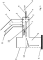
- Fig. 1 shows a typical design of a pellet induration furnace, especially of an iron ore pellet induration furnace, according to the state of the art.
- a burner assembly 1 according to the state of the art, e.g. US 2016/0201904 A1 is shown in a sectional view.
- the burner assembly 1 features a combustion chamber 2 being cylindrical-shaped with a sectional diameter D, and, therefore, being symmetrical around its centerline a.
- the combustion chamber 2 works as a flame-reaction space.
- Fig. 1 depicts the situation known from the state of the art, position o is located on the centerline a, resulting in the distance
- Furnace 3 is designed such that two burner assemblies, on opposite positions are used, which is indicted by the symmetry plane b.
- liquid or gaseous fuel as well as a primary oxidant, preferably air, are injected into the combustion chamber 2.
- a control unit or equipment (not shown) is provided for controlling the supplies of fuel and primary air into the combustion chamber.
- the majority of oxidant is typically injected via a downcomer 5 through which secondary oxidant, e.g. preheated air, is flowing downwards into the combustion chamber 2.
- the lower part of the downcomer features a center line c next to its intersection area S with the combustion chamber 2.
- the intersection of the center line c and the intersection area S is defined as position i.
- the secondary oxidant is passing the burner lance 4 and the flame 7 before it is creating a recirculation zone 12.
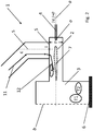
- Fig. 2 basically the same structure is used. However, instead of gas stream lines, Fig. 2 shows a simplified temperature profile in the furnace, e.g. above a pellet bed 6. Thereby, T 1 indicates a hot zone while T 2 indicates a colder zone. Typically a difference of at least 40 K is found between these two zones.
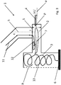
- Fig. 3 shows the same burner and furnace assembly, which the inventive method may be applied to.
- the burner lance 4 is positioned in the position p with its smallest distance
- to the centerline a of the combustion chamber 2, where d 1 is defined as d 1 1 ⁇ d ⁇ u 1 u 2 1 4 ⁇ D 2 , whereby d is in the range of 0.05 to 0.15. Since d 1 ends up with a positive sign, position p is always closer to the downcomer than in the case it ends up with a negative sign.
- the flame 7 interacts with the recirculation zone 12, so highly turbulent flow conditions are found in furnace 3.
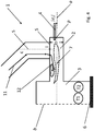
- Fig. 4 shows a more homogenous temperature profile, symbolized by a nearly identical size of T 1 (hot zone) and T 2 (colder zone) with a difference in CFD simulations of maximum 10 K between T 1 and T 2 .
- Fig. 5 and 6 correspond to fig. 3 and 4 , but shows an inclined burner lance.
- the inclination angle ⁇ is measured between the centerline a of the combustion chamber and the centerline of the burner lance 4.
Landscapes
- Engineering & Computer Science (AREA)
- Chemical & Material Sciences (AREA)
- Combustion & Propulsion (AREA)
- Mechanical Engineering (AREA)
- General Engineering & Computer Science (AREA)
- Combustion Of Fluid Fuel (AREA)
- Vertical, Hearth, Or Arc Furnaces (AREA)
Description
- The invention relates to a method for combustion of gaseous or liquid fuel in a combustion chamber which can have a cylindrical shape with a sectional diameter D whereby gaseous or liquid fuel as well as primary oxidant with a mean velocity of u1 is introduced via a burner lance (including a nozzle head) into the combustion chamber.
- Secondary oxidant with a mean velocity of u2 is introduced via a downcomer into the combustion chamber. Certain industrial processes, such as heating a load in an attached furnace, rely on heat produced by the combustion of fuel and oxidant. The fuel is typically natural gas or oil. The oxidant is typically air, vitiated air, oxygen, or air enriched with oxygen. The used burner assemblies typically feature a combustion chamber with at least one burner lance for introducing a gaseous or liquid fuel and primary oxidant and, optionally, a means of supply for secondary oxidant, e.g. a downcomer for secondary air. According to the state of the art the combustion chamber has a horizontal centerline, the downcomer for secondary air has a vertical centerline at the intersection with the combustion chamber, and the burner lance has a horizontal centerline and is located in the centerline of the combustion chamber at the closed end plate of the combustion chamber (see e.g.
US 2016/0201904 A1 , which the two-part form ofclaim 1 is based on). - Out of the following reasons, a technological challenge in such burner assemblies is a non-uniform temperature profile: At first, a non-uniform temperature profile leads to thermal stress on the wall of the combustion chamber. At second, hot-spots in the flame will increase the formation of NOx. Moreover, a non-uniform temperature profile in the combustion chamber usually leads to a non-uniform temperature profile in the attached furnace where a load is to be treated thermally. This in turn leads to a non-uniform product quality of the heat-treated load.
- This last argument should be explained in more detail with regard to the pellet induration in iron ore pelletizing plants: Now, the pellet bed exhibits a non-uniform temperature distribution in horizontal direction, which is due to the local formation of hot zones in the furnace due to convective heat transfer from the flame inside the combustion chamber. Since the flame occupies only a limited space and the surrounding space is occupied by colder secondary air from the downcomer, a huge temperature gradient can be observed along the radius of the combustion chamber at its intersection with the furnace as well as across the width of the furnace itself. With the hot zones being in the center of the furnace, i.e. of the pellet bed, a large variation in the quality of the pellets over the width of the furnace is created.
- Typically, a reduction of NOx emissions should be achieved by injecting a mixture of oxidant and fuel. Document
US 8,202,470 B2 describes a burner assembly of an indurating furnace with an air passage leading to the heating station. A draft of preheated recirculation air is driven through a passage towards the heating station, and is mixed with fuel gas to form a combustible mixture that ignites in the passage. This is accomplished by injecting the fuel gas into the passage in a stream that does not form a combustible mixture with the preheated recirculation air before entering the passage. - Document
WO 2015/018438 A1 teaches a burner assembly wherein combustion air is injected into the combustion chamber such that it passes the burner and is then deflected such that the flow of preheated combustion air and the smaller flows of fuel and primary air are flowing mainly in parallel from the burner to the furnace of the mixer tubes into the combustion chamber to mix with the combustion air. -
WO 2013/023116 A1 teaches a method for delivering fuel gas to a furnace combustion chamber from the premix burner having a reaction zone with an outlet to the furnace combustion chamber. This includes the steps of injecting the premix of primary fuel gas and combustion air into the reaction zone, and combusting the premix to provide combustion products including vitiated combustion air in the reaction zone. Further steps include injecting staged fuel gas into the reaction zone separately from the premix, discharging the staged fuel gas and vitiated combustion air from the reaction zone through the outlet to the furnace combustion chamber, and combusting the staged fuel gas and vitiated combustion air in the furnace combustion chamber. This enables low NOx combustion in the furnace combustion chamber to be achieved as a result of interacting to staged fuel gas with the vitiated combustion air in the reaction zone. -
WO 2010/111217 A1 discloses a NOx suppression apparatus configured for use with a burner that injects fuel into a stream of process air flowing into and through a rotary kiln. The apparatus comprises a premix injection system that forms the premix of fuel gas and air, and injects the premix into the stream of process air upstream of a burner port. This enables premixed products of combustion to suppress the production of NOx by vitiating a combustion air portion of the process air before the combustion air portion combusts with fuel injected from the burner port. - However, the described solutions do not prevent parts of the combustion chamber suffering from high local thermal stress. Also, these documents are not dealing with the basic effect of a temperature gradient, but try to avoid very high temperature hot-spots as cause for high NOx emissions only.
- Therefore, it is the object of the invention to create a more uniform gas temperature in the complete furnace.
- This problem is solved with a method according to
claim 1. - Such a method comprises the introduction of gaseous or liquid fuel and primary oxidant into a combustion chamber through a burner lance. Each of the fluids in the burner lance, e.g. fuel and primary oxidant, is introduced with a certain velocity, whereby one stream can be faster than the other (at the entry into the combustion chamber). The mean velocity in the burner lance at the entry into the combustion chamber is defined as u1 . Further, a secondary oxidant is introduced via a downcomer into the combustion chamber, featuring a mean velocity u2 (at the entry into the combustion chamber). The combustion chamber is typically cylinder-shaped with a sectional diameter D and symmetric to a centerline (it can also have other shapes).
- Preferably, u1 is bigger than u2 . Most preferably, the ratio u1 /u2 is between 0.1 and 20.0.
- It is the essential part of the invention that the burner lance is adjusted in a position p (measured from the tip of the burner lance) such that position p has a distance |d1 | defined as the smallest distance between p and the combustion chamber centerline. Moreover, the distance |d1 | from position p to the intersection point i of the downcomer centerline (at the part of the downcomer next to the intersection area S) and the contact surface of combustion chamber and downcomer is smaller than the distance |dc |. Distance |dc | is defined as the distance from the intersection of the combustion chamber centerline and the shortest connection between p and the combustion chamber centerline a to the intersection i of the downcomer centerline and the intersection area S of combustion chamber and downcomer.
- According to the invention, the burner lance is arranged in a position p such that position p has a smallest distance |d1 |, whereby d1 has a positive sign, to the combustion chamber centerline whereby |d1 | defined as


- Computational fluid dynamics (CFD) simulations have shown that by repositioning the lance into the position p according to the invention, a temperature gradient |ΔT| with |ΔT| = T pelletbedsurface,max -T pelletbedsurface,min of less than 10K was found. This is much lower than in the state of the art, where |ΔT| typically amounts to 40K. The reason for the improvement is the interaction of the flame and the recirculation zone in the combustion chamber.
- By positioning the burner lance to a higher position p relative to the combustion chamber centerline in the sense that the distance between the lower end of the downcomer and the centerline of the burner lance is reduced, a flame deflection can be induced. This deflection is caused in a recirculation zone due to the preheated secondary oxidant redirection from the downcomer to the combustion chamber. The flame which is placed at a slightly higher location in accordance with the invention due to the repositioned burner lance gets sucked in by the recirculation zone and finally deflected. This deflection in turn modifies the angle under which the resulting hot flue gas meets the flue gas from the oppositely placed combustion chamber. According to the state of the art the flow path of the hottest part of the flue gas in the furnace is directed downwards, according to the invention it is directed upwards.
- A further benefit of the invention is a temperature reduction at the hottest part of the combustion chamber wall: At standard configurations according to the state of the art, higher temperatures at the combustion chamber bottom wall are found, caused by a certain flame deflection inside the combustion chamber towards its bottom. The configuration according to the invention leads to a significantly bigger flame distance to the bottom wall, and thus the bottom wall temperature is reduced. This reduces the risk of thermal damages and may even allow for an increase of the burner capacity.
- The invention claims the new burner lance placement with the non-dimensional factor d being in a range of 0.05 to 0.15, preferably in the range of 0.075 to 0.125 and most preferably in the range of 0.09 to 0.11. For a typical use of burner assembly according to the state of the art with a burner lance in the centerline of the combustion chamber the factor d would be in the range from 0.2 to 0.3.
- If the factor d exceeds 0.15, then the distance between flame and recirculation zone is too big, consequently no flame deflection takes place. If the factor d is lower than 0.05, then the distance between flame and recirculation zone is too small, consequently the gas temperature in the recirculation zone increases strongly. Consequently, the upper wall temperature rises what may cause thermal damages.
- It is preferred that the mean velocity u1 is less than 200 m/s, preferably in a range between 70 and 140 m/s. Thereby, a reasonable pressure drop in the lance or the lance head is achieved as well as lower NOx formation.
- Moreover, according to the invention it is preferred to introduce the secondary oxidant into the combustion chamber with a mean velocity u2 between 10 and 35 m/s to ensure a good distribution of the fuel.
- In principal, each gas with any oxygen content can be used as an oxidant. However, air or air enriched with oxygen is most common due to cost reasons. The following description relates to air as the primary and secondary oxidant.
- Another relevant parameter is the total air ratio λ with

- Out of the same reasons, the primary air ratio λprim with

- A typical burner lance has a capacity in the range of 2 and 6 MW. This enables the use in typical industrial furnaces.
- A burner assembly that may be used with the method according to the invention comprises a cylinder-shaped, rectangular or otherwise shaped combustion chamber with a centerline and a hydraulic diameter D. At least one burner lance is used as a supply for gaseous or liquid fuel and primary oxidant with a mean velocity u1 and one downcomer as a supply for secondary oxidant with a mean velocity u 2.
- The burner lance is adjusted in a position p (measured from the tip of the burner lance) such that position p has a distance |d1 | defined as the smallest distance between p and the combustion chamber centerline. Moreover, the distance |d1 | from position p to the intersection of the downcomer centerline and the intersection area S of combustion chamber and downcomer is smaller than the distance |dc|. Distance |dc | is defined as the distance from the intersection of the combustion centerline and the shortest connection between p and the combustion chamber centerline a to the intersection point i of the downcomer centerline and the intersection area S of combustion chamber and downcomer.
- The burner lance is arranged in a position p such that position p has a smallest distance |d1 | to the
combustion chamber centerline 1 whereby |d1 | defined as

- By including an inclination angle α of the burner lance to the combustion chamber centerline, the positive effect of the recirculation zone on the flame behavior and on the temperature distribution in the furnace can be amplified. This inclination angle α should not exceed values larger than 12°, preferably it should be smaller than 10°, since otherwise the flame would get in direct contact with the upper combustion chamber wall. The inclination angle α may be chosen in such a way that the burner lance, respectively nozzle head is pointing into the direction of the downcomer.
- Typically, the combustion chamber diameter D lies between 0.5 and 1.8 m, so it fits well to industrial furnaces.
- At least two, preferably arranged symmetrically, burner assembiles may be designed in a pellet induration furnace. By inducing a swirl in the furnace, mixing can be enhanced and therefore even more homogeneous temperature profiles can be obtained. This in turn improves the uniformity of the pellet quality. The swirl is induced by a modified impingement angle of the hot combustion gases stemming from two oppositely placed combustion chambers. The modified impingement angle itself is a result of a higher situated burner lance (fuel and primary oxidant), which leads to a flame bending due to partial interference of the flame with the recirculation zone placed on the upper combustion chamber wall.
- The hot gases from the flame are redirected several times due to symmetry planes to the next burner in one row as well as impingement on the furnace walls. This creates a huge swirl system leading to enhanced flow mixing and finally to a uniform temperature distribution of the flue gas above the pellet bed. The recirculation zone, which deflects the flame, does thereby not get heated up significantly by hot flame gases.
- The hot zone can hereby be moved from the symmetry plane of the furnace towards the side walls of the furnace. This is of advantage, because the heat losses are higher in the vicinity of the furnace side walls as compared to the symmetry plane of the furnace.
- The new position of the burner lance can be easily realized by installing appropriate burner assemblies, which is why also existing plants can be optimized. The implementation of this invention is especially much more economic than other possible approaches in existing plants, because the arrangement of the downcomer can remain as it is according to the state of the art, i.e. with a vertical centerline in its lower portion. This typically results in a 90° angle between the centerline of the lower portion of the downcomer and the combustion chamber centerline, because typically the combustion chamber has a horizontal centerline.
- The lower part of the downcomer itself does not have to align with the combustion chamber with an angle of 90° but can be also inclined, leading to angles smaller or larger than 90°. The exact value of the inclination does not matter, as the recirculation zone will be created under a wide range of possible inclination angles. However, changing the angle of the downcomer in an existing pellet induration furnace is hardly possible because of space and cost limitations.
- The invention will now be described in more detail on the basis of the following description of preferred embodiments and the drawings. In detail, the state of the art design will be compared to the modified design by means of drawings explaining the modified flame behavior, the swirling effect as well as the development of hot and cold zones at the oven outlet.
- In the drawings:
- Fig. 1
- shows a design of a pellet induration furnace according to the state of the art focusing on flow conditions,
- Fig. 2
- shows a design of a pellet induration furnace according to the state of the art focusing on the temperature profile in the furnace,
- Fig. 3
- shows a first design of a pellet induration furnace applying the invention focusing on flow conditions,
- Fig. 4
- shows a first design of a pellet induration furnace applying the invention focusing on the temperature profile in the furnace,
- Fig. 5
- shows a second design of a pellet induration furnace applying the invention focusing on flow conditions,
- Fig. 6
- shows a second design of a pellet induration furnace applying the invention focusing on the temperature profile in the furnace.
-
Fig. 1 shows a typical design of a pellet induration furnace, especially of an iron ore pellet induration furnace, according to the state of the art. Aburner assembly 1 according to the state of the art, e.g.US 2016/0201904 A1 is shown in a sectional view. - The
burner assembly 1 features acombustion chamber 2 being cylindrical-shaped with a sectional diameter D, and, therefore, being symmetrical around its centerline a. Thecombustion chamber 2 works as a flame-reaction space. - On the left side of
Fig. 1 , thecombustion chamber 2 opens into afurnace 3. On the opposite side, aburner lance 4 is positioned at position o. AsFig. 1 depicts the situation known from the state of the art, position o is located on the centerline a, resulting in the distance |d1 | being equal to 0. -
Furnace 3 is designed such that two burner assemblies, on opposite positions are used, which is indicted by the symmetry plane b. - Via the
burner lance 4, liquid or gaseous fuel as well as a primary oxidant, preferably air, are injected into thecombustion chamber 2. Typically, also a control unit or equipment (not shown) is provided for controlling the supplies of fuel and primary air into the combustion chamber. - The majority of oxidant is typically injected via a
downcomer 5 through which secondary oxidant, e.g. preheated air, is flowing downwards into thecombustion chamber 2. The lower part of the downcomer features a center line c next to its intersection area S with thecombustion chamber 2. The intersection of the center line c and the intersection area S is defined as position i. As shown viaarrows 11, the secondary oxidant is passing theburner lance 4 and the flame 7 before it is creating arecirculation zone 12. - Inside the
furnace 3, the flue gas coming from thecombustion chamber 2 is flowing downwards (shown via arrows 13), e.g. into thepellet bed 6. - In
Fig. 2 , basically the same structure is used. However, instead of gas stream lines,Fig. 2 shows a simplified temperature profile in the furnace, e.g. above apellet bed 6. Thereby, T1 indicates a hot zone while T2 indicates a colder zone. Typically a difference of at least 40 K is found between these two zones. - In comparison,
Fig. 3 shows the same burner and furnace assembly, which the inventive method may be applied to. As described, theburner lance 4 is positioned in the position p with its smallest distance |d1 | to the centerline a of thecombustion chamber 2, where d1 is defined as
- As shown in
Fig.3 , the flame 7 interacts with therecirculation zone 12, so highly turbulent flow conditions are found infurnace 3. - As a result, a better mixing of the gas flow is achieved inside the
furnace 3, which is whyFig. 4 shows a more homogenous temperature profile, symbolized by a nearly identical size of T1 (hot zone) and T2 (colder zone) with a difference in CFD simulations of maximum 10 K between T1 and T2. -
Fig. 5 and6 correspond tofig. 3 and4 , but shows an inclined burner lance. The inclination angle α is measured between the centerline a of the combustion chamber and the centerline of theburner lance 4. -
- 1
- burner assembly
- 2
- combustion chamber
- 3
- furnace
- 4
- burner lance
- 5
- downcomer
- 6
- pellet bed
- 7
- flame
- 11
- flow of the secondary oxidant
- 12
- recirculation zone
- 13
- flow of the gas in the furnace
- T1
- Temperature in the hot zone
- T2
- Temperature in the colder zone
- a
- centerline of the combustion chamber
- a
- inclination angle
- b
- symmetry plane of the furnace
- c
- centerline of the downcomer (next to the intersection area S)
- D
- sectional diameter of the combustion chamber
- d
- dimensionless factor
- |d1|
- smallest distance of position p to the combustion chamber centerline a
- i
- intersection of the downcomer centerline c and the intersection area S of combustion chamber and downcomer
- o
- position of the burner lance according to the state of the art
- p
- position of the burner lance according to the invention
- S
- intersection area of combustion chamber (2) and downcomer (5)
- u1
- mean velocity in the burner lance at the entry to the combustion chamber
- u2
- mean velocity of the secondary oxidant in the downcomer
Claims (8)
- Method for combustion of gaseous or liquid fuel in a combustion chamber (2) with a hydraulic diameter D, whereby the fuel as well as the primary oxidant are introduced via a burner lance (4) into the combustion chamber (2), whereby fuel and primary oxidant have a certain mean velocity u1 at the entry from the burner lance (4) into the combustion chamber (2), whereby the mean velocity u1 is defined as
 the burner lance (4) is arranged in a position p measured from the tip of the burner lance such that position p has a distance |d1 | defined as the smallest distance between p and a combustion chamber centerline a, that the burner lance is arranged such that the distance from position p to an intersection point i of a downcomer centerline and an intersection area S of combustion chamber and downcomer is smaller than the distance |dc | from the intersection of the combustion chamber centerline a and the shortest connection between p and the combustion chamber centerline a to the intersection point i of the downcomer centerline c and the intersection area S of combustion chamber (2) and downcomer (5),characterized in thatthe value of |d1 | is defined as
- Method according to claim 1, characterized in that d is in the range of 0.09 to 0.11.
- Method according to any of the preceding claims, characterized in that the primary and/or the secondary oxidant is air.
- Method according to any of the preceding claims, characterized in that the mean velocity u1 is less than 200 m/s.
- Method according to any of the preceding claims, characterized in that the secondary oxidant is introduced into the combustion chamber (2) with a mean velocity u2 between 10 and 35 m/s.
- Method according to any of the preceding claims, characterized in that the total air ratio λ with

- Method according to any of the preceding claims, characterized in that the primary air ratio λprim with

- Method according to any of the preceding claims, characterized in that the burner lance has a fuel capacity in the range of 2 and 6 MW.
Applications Claiming Priority (1)
| Application Number | Priority Date | Filing Date | Title |
|---|---|---|---|
| PCT/EP2017/064412 WO2018228677A1 (en) | 2017-06-13 | 2017-06-13 | Method and apparatus for combustion of gaseous or liquid fuel |
Publications (2)
| Publication Number | Publication Date |
|---|---|
| EP3638952A1 EP3638952A1 (en) | 2020-04-22 |
| EP3638952B1 true EP3638952B1 (en) | 2021-10-27 |
Family
ID=59215738
Family Applications (1)
| Application Number | Title | Priority Date | Filing Date |
|---|---|---|---|
| EP17732826.7A Active EP3638952B1 (en) | 2017-06-13 | 2017-06-13 | Method for combustion of gaseous or liquid fuel |
Country Status (8)
| Country | Link |
|---|---|
| US (1) | US11428404B2 (en) |
| EP (1) | EP3638952B1 (en) |
| CN (1) | CN110741204B (en) |
| EA (1) | EA038251B1 (en) |
| ES (1) | ES2901606T3 (en) |
| MX (1) | MX2019014694A (en) |
| UA (1) | UA122756C2 (en) |
| WO (1) | WO2018228677A1 (en) |
Family Cites Families (16)
| Publication number | Priority date | Publication date | Assignee | Title |
|---|---|---|---|---|
| US7229281B2 (en) * | 2000-09-11 | 2007-06-12 | Cadence Environmental Energy, Inc. | Method of mixing high temperature gases in mineral processing kilns |
| US7175423B1 (en) * | 2000-10-26 | 2007-02-13 | Bloom Engineering Company, Inc. | Air staged low-NOx burner |
| EP1585920B1 (en) * | 2003-01-21 | 2010-10-20 | L'AIR LIQUIDE, Société Anonyme pour l'Etude et l'Exploitation des Procédés Georges Claude | Process and apparatus for oxygen enrichment in fuel conveying gases |
| CN2926828Y (en) * | 2006-02-20 | 2007-07-25 | 胡建廷 | Economic supersonic oil gun |
| EP2080972A1 (en) * | 2008-01-08 | 2009-07-22 | L'AIR LIQUIDE, Société Anonyme pour l'Etude et l'Exploitation des Procédés Georges Claude | Combined burner and lance apparatus for electric arc furnaces |
| US8986002B2 (en) * | 2009-02-26 | 2015-03-24 | 8 Rivers Capital, Llc | Apparatus for combusting a fuel at high pressure and high temperature, and associated system |
| US8202470B2 (en) | 2009-03-24 | 2012-06-19 | Fives North American Combustion, Inc. | Low NOx fuel injection for an indurating furnace |
| US8662887B2 (en) * | 2009-03-24 | 2014-03-04 | Fives North American Combustion, Inc. | NOx suppression techniques for a rotary kiln |
| CN201589260U (en) * | 2009-11-30 | 2010-09-22 | 中国船舶重工集团公司第七○三研究所 | High-viscosity oil burner |
| SE535240C2 (en) * | 2010-10-26 | 2012-06-05 | Luossavaara Kiirunavaara Ab | Procedure, apparatus and ball interfaces |
| US20130203003A1 (en) * | 2011-08-10 | 2013-08-08 | Bruce E. Cain | Low NOx Fuel Injection for an Indurating Furnace |
| CN202902271U (en) * | 2012-10-22 | 2013-04-24 | 瑞焓能源科技有限公司 | Industrial boiler burner and industrial boiler with the same |
| UA119241C2 (en) | 2013-08-06 | 2019-05-27 | Оутотек (Фінленд) Ой | BURNER UNIT AND METHOD OF GASIFICATION OF LIQUID OR LIQUID FUEL |
| CN204187614U (en) * | 2014-11-03 | 2015-03-04 | 河北博广环保设备制造有限公司 | The liquid fuel atomizer of industrial furnace |
| DE102015107360A1 (en) * | 2015-05-11 | 2016-11-17 | Outotec (Finland) Oy | Low NOx combustion system for traveling grate pelleting plants |
| CN106705039A (en) * | 2017-03-06 | 2017-05-24 | 中国华能集团清洁能源技术研究院有限公司 | Low-load stable combustion rotational flow type burner |
-
2017
- 2017-06-13 CN CN201780091888.6A patent/CN110741204B/en active Active
- 2017-06-13 ES ES17732826T patent/ES2901606T3/en active Active
- 2017-06-13 US US16/619,995 patent/US11428404B2/en active Active
- 2017-06-13 EA EA201992650A patent/EA038251B1/en unknown
- 2017-06-13 UA UAA201911695A patent/UA122756C2/en unknown
- 2017-06-13 EP EP17732826.7A patent/EP3638952B1/en active Active
- 2017-06-13 MX MX2019014694A patent/MX2019014694A/en unknown
- 2017-06-13 WO PCT/EP2017/064412 patent/WO2018228677A1/en not_active Ceased
Non-Patent Citations (1)
| Title |
|---|
| None * |
Also Published As
| Publication number | Publication date |
|---|---|
| EA038251B1 (en) | 2021-07-30 |
| MX2019014694A (en) | 2020-02-07 |
| UA122756C2 (en) | 2020-12-28 |
| WO2018228677A1 (en) | 2018-12-20 |
| BR112019025859A2 (en) | 2020-07-14 |
| US20210080103A1 (en) | 2021-03-18 |
| CN110741204B (en) | 2021-10-29 |
| CA3066495A1 (en) | 2018-12-20 |
| US11428404B2 (en) | 2022-08-30 |
| ES2901606T3 (en) | 2022-03-23 |
| EA201992650A1 (en) | 2020-04-22 |
| CN110741204A (en) | 2020-01-31 |
| EP3638952A1 (en) | 2020-04-22 |
Similar Documents
| Publication | Publication Date | Title |
|---|---|---|
| US11078429B2 (en) | Burner, furnace, and steam cracking processes using the same | |
| EP1495263B1 (en) | IMPROVED BURNER WITH LOW NOx EMISSIONS | |
| US9134025B2 (en) | Rapid energy release burners and methods for using the same | |
| CN102439363A (en) | Combustion system with precombustor for recycled flue gas | |
| US11649960B2 (en) | Low NOx burner with bypass conduit | |
| EP2941594B1 (en) | Method for combusting fuel and burner therefor | |
| CN102449394A (en) | NOx Suppression Technology of Rotary Furnace | |
| CN107580669B (en) | Low-nitrogen oxide combustion system for movable grate type pellet equipment | |
| RU2493113C2 (en) | Inter-channel oxygen-fuel burner | |
| Ashouri et al. | Enhancing thermal performance and reducing pollutant emissions in a steel reheating furnace through MILD combustion: A study on air distribution and outlet design | |
| US11428404B2 (en) | Method and apparatus for combustion of gaseous or liquid fuel | |
| CA3066495C (en) | Method and apparatus for combustion of gaseous or liquid fuel | |
| EP2665970B1 (en) | Burner and a furnace comprising such a burner | |
| EP2811228A1 (en) | Burner | |
| EP1495262B1 (en) | Burner system with improved flue gas recirculation | |
| TWI416051B (en) | Through-port oxy-fuel burner | |
| EP4400766A1 (en) | Low nox emission burner and operating method for reducing nox formation applied to an iron ore pellet sintering and/or hardening method | |
| Flame | Flame interaction and rollover solutions in ethylene cracking furnaces | |
| BR112019025859B1 (en) | METHOD FOR COMBUSTION OF GASEOUS OR LIQUID FUEL IN A COMBUSTION CHAMBER AND MOUNTING A BURNER IN A COMBUSTION CHAMBER |
Legal Events
| Date | Code | Title | Description |
|---|---|---|---|
| STAA | Information on the status of an ep patent application or granted ep patent |
Free format text: STATUS: UNKNOWN |
|
| STAA | Information on the status of an ep patent application or granted ep patent |
Free format text: STATUS: THE INTERNATIONAL PUBLICATION HAS BEEN MADE |
|
| PUAI | Public reference made under article 153(3) epc to a published international application that has entered the european phase |
Free format text: ORIGINAL CODE: 0009012 |
|
| STAA | Information on the status of an ep patent application or granted ep patent |
Free format text: STATUS: REQUEST FOR EXAMINATION WAS MADE |
|
| 17P | Request for examination filed |
Effective date: 20191114 |
|
| AK | Designated contracting states |
Kind code of ref document: A1 Designated state(s): AL AT BE BG CH CY CZ DE DK EE ES FI FR GB GR HR HU IE IS IT LI LT LU LV MC MK MT NL NO PL PT RO RS SE SI SK SM TR |
|
| AX | Request for extension of the european patent |
Extension state: BA ME |
|
| DAV | Request for validation of the european patent (deleted) | ||
| DAX | Request for extension of the european patent (deleted) | ||
| STAA | Information on the status of an ep patent application or granted ep patent |
Free format text: STATUS: EXAMINATION IS IN PROGRESS |
|
| 17Q | First examination report despatched |
Effective date: 20201021 |
|
| GRAP | Despatch of communication of intention to grant a patent |
Free format text: ORIGINAL CODE: EPIDOSNIGR1 |
|
| STAA | Information on the status of an ep patent application or granted ep patent |
Free format text: STATUS: GRANT OF PATENT IS INTENDED |
|
| INTG | Intention to grant announced |
Effective date: 20210708 |
|
| GRAS | Grant fee paid |
Free format text: ORIGINAL CODE: EPIDOSNIGR3 |
|
| GRAA | (expected) grant |
Free format text: ORIGINAL CODE: 0009210 |
|
| STAA | Information on the status of an ep patent application or granted ep patent |
Free format text: STATUS: THE PATENT HAS BEEN GRANTED |
|
| AK | Designated contracting states |
Kind code of ref document: B1 Designated state(s): AL AT BE BG CH CY CZ DE DK EE ES FI FR GB GR HR HU IE IS IT LI LT LU LV MC MK MT NL NO PL PT RO RS SE SI SK SM TR |
|
| REG | Reference to a national code |
Ref country code: GB Ref legal event code: FG4D |
|
| REG | Reference to a national code |
Ref country code: CH Ref legal event code: EP |
|
| REG | Reference to a national code |
Ref country code: AT Ref legal event code: REF Ref document number: 1442111 Country of ref document: AT Kind code of ref document: T Effective date: 20211115 |
|
| REG | Reference to a national code |
Ref country code: DE Ref legal event code: R096 Ref document number: 602017048263 Country of ref document: DE |
|
| REG | Reference to a national code |
Ref country code: IE Ref legal event code: FG4D |
|
| REG | Reference to a national code |
Ref country code: NL Ref legal event code: FP |
|
| REG | Reference to a national code |
Ref country code: SE Ref legal event code: TRGR |
|
| REG | Reference to a national code |
Ref country code: LT Ref legal event code: MG9D |
|
| REG | Reference to a national code |
Ref country code: AT Ref legal event code: MK05 Ref document number: 1442111 Country of ref document: AT Kind code of ref document: T Effective date: 20211027 |
|
| REG | Reference to a national code |
Ref country code: ES Ref legal event code: FG2A Ref document number: 2901606 Country of ref document: ES Kind code of ref document: T3 Effective date: 20220323 |
|
| PG25 | Lapsed in a contracting state [announced via postgrant information from national office to epo] |
Ref country code: RS Free format text: LAPSE BECAUSE OF FAILURE TO SUBMIT A TRANSLATION OF THE DESCRIPTION OR TO PAY THE FEE WITHIN THE PRESCRIBED TIME-LIMIT Effective date: 20211027 Ref country code: LT Free format text: LAPSE BECAUSE OF FAILURE TO SUBMIT A TRANSLATION OF THE DESCRIPTION OR TO PAY THE FEE WITHIN THE PRESCRIBED TIME-LIMIT Effective date: 20211027 Ref country code: FI Free format text: LAPSE BECAUSE OF FAILURE TO SUBMIT A TRANSLATION OF THE DESCRIPTION OR TO PAY THE FEE WITHIN THE PRESCRIBED TIME-LIMIT Effective date: 20211027 Ref country code: BG Free format text: LAPSE BECAUSE OF FAILURE TO SUBMIT A TRANSLATION OF THE DESCRIPTION OR TO PAY THE FEE WITHIN THE PRESCRIBED TIME-LIMIT Effective date: 20220127 Ref country code: AT Free format text: LAPSE BECAUSE OF FAILURE TO SUBMIT A TRANSLATION OF THE DESCRIPTION OR TO PAY THE FEE WITHIN THE PRESCRIBED TIME-LIMIT Effective date: 20211027 |
|
| PG25 | Lapsed in a contracting state [announced via postgrant information from national office to epo] |
Ref country code: IS Free format text: LAPSE BECAUSE OF FAILURE TO SUBMIT A TRANSLATION OF THE DESCRIPTION OR TO PAY THE FEE WITHIN THE PRESCRIBED TIME-LIMIT Effective date: 20220227 Ref country code: PT Free format text: LAPSE BECAUSE OF FAILURE TO SUBMIT A TRANSLATION OF THE DESCRIPTION OR TO PAY THE FEE WITHIN THE PRESCRIBED TIME-LIMIT Effective date: 20220228 Ref country code: PL Free format text: LAPSE BECAUSE OF FAILURE TO SUBMIT A TRANSLATION OF THE DESCRIPTION OR TO PAY THE FEE WITHIN THE PRESCRIBED TIME-LIMIT Effective date: 20211027 Ref country code: NO Free format text: LAPSE BECAUSE OF FAILURE TO SUBMIT A TRANSLATION OF THE DESCRIPTION OR TO PAY THE FEE WITHIN THE PRESCRIBED TIME-LIMIT Effective date: 20220127 Ref country code: LV Free format text: LAPSE BECAUSE OF FAILURE TO SUBMIT A TRANSLATION OF THE DESCRIPTION OR TO PAY THE FEE WITHIN THE PRESCRIBED TIME-LIMIT Effective date: 20211027 Ref country code: HR Free format text: LAPSE BECAUSE OF FAILURE TO SUBMIT A TRANSLATION OF THE DESCRIPTION OR TO PAY THE FEE WITHIN THE PRESCRIBED TIME-LIMIT Effective date: 20211027 Ref country code: GR Free format text: LAPSE BECAUSE OF FAILURE TO SUBMIT A TRANSLATION OF THE DESCRIPTION OR TO PAY THE FEE WITHIN THE PRESCRIBED TIME-LIMIT Effective date: 20220128 |
|
| REG | Reference to a national code |
Ref country code: DE Ref legal event code: R097 Ref document number: 602017048263 Country of ref document: DE |
|
| PG25 | Lapsed in a contracting state [announced via postgrant information from national office to epo] |
Ref country code: SM Free format text: LAPSE BECAUSE OF FAILURE TO SUBMIT A TRANSLATION OF THE DESCRIPTION OR TO PAY THE FEE WITHIN THE PRESCRIBED TIME-LIMIT Effective date: 20211027 Ref country code: SK Free format text: LAPSE BECAUSE OF FAILURE TO SUBMIT A TRANSLATION OF THE DESCRIPTION OR TO PAY THE FEE WITHIN THE PRESCRIBED TIME-LIMIT Effective date: 20211027 Ref country code: RO Free format text: LAPSE BECAUSE OF FAILURE TO SUBMIT A TRANSLATION OF THE DESCRIPTION OR TO PAY THE FEE WITHIN THE PRESCRIBED TIME-LIMIT Effective date: 20211027 Ref country code: EE Free format text: LAPSE BECAUSE OF FAILURE TO SUBMIT A TRANSLATION OF THE DESCRIPTION OR TO PAY THE FEE WITHIN THE PRESCRIBED TIME-LIMIT Effective date: 20211027 Ref country code: DK Free format text: LAPSE BECAUSE OF FAILURE TO SUBMIT A TRANSLATION OF THE DESCRIPTION OR TO PAY THE FEE WITHIN THE PRESCRIBED TIME-LIMIT Effective date: 20211027 Ref country code: CZ Free format text: LAPSE BECAUSE OF FAILURE TO SUBMIT A TRANSLATION OF THE DESCRIPTION OR TO PAY THE FEE WITHIN THE PRESCRIBED TIME-LIMIT Effective date: 20211027 |
|
| PLBE | No opposition filed within time limit |
Free format text: ORIGINAL CODE: 0009261 |
|
| STAA | Information on the status of an ep patent application or granted ep patent |
Free format text: STATUS: NO OPPOSITION FILED WITHIN TIME LIMIT |
|
| 26N | No opposition filed |
Effective date: 20220728 |
|
| PG25 | Lapsed in a contracting state [announced via postgrant information from national office to epo] |
Ref country code: AL Free format text: LAPSE BECAUSE OF FAILURE TO SUBMIT A TRANSLATION OF THE DESCRIPTION OR TO PAY THE FEE WITHIN THE PRESCRIBED TIME-LIMIT Effective date: 20211027 |
|
| PG25 | Lapsed in a contracting state [announced via postgrant information from national office to epo] |
Ref country code: SI Free format text: LAPSE BECAUSE OF FAILURE TO SUBMIT A TRANSLATION OF THE DESCRIPTION OR TO PAY THE FEE WITHIN THE PRESCRIBED TIME-LIMIT Effective date: 20211027 |
|
| REG | Reference to a national code |
Ref country code: DE Ref legal event code: R081 Ref document number: 602017048263 Country of ref document: DE Owner name: METSO OUTOTEC FINLAND OY, FI Free format text: FORMER OWNER: OUTOTEC (FINLAND) OY, ESPOO, FI |
|
| REG | Reference to a national code |
Ref country code: NL Ref legal event code: PD Owner name: METSO MINERALS OY; FI Free format text: DETAILS ASSIGNMENT: CHANGE OF OWNER(S), MERGE; FORMER OWNER NAME: OUTOTEC (FINLAND) OY Effective date: 20230118 Ref country code: NL Ref legal event code: HC Owner name: METSO OUTOTEC FINLAND OY; FI Free format text: DETAILS ASSIGNMENT: CHANGE OF OWNER(S), CHANGE OF OWNER(S) NAME; FORMER OWNER NAME: METSO MINERALS OY Effective date: 20230118 |
|
| PG25 | Lapsed in a contracting state [announced via postgrant information from national office to epo] |
Ref country code: MC Free format text: LAPSE BECAUSE OF FAILURE TO SUBMIT A TRANSLATION OF THE DESCRIPTION OR TO PAY THE FEE WITHIN THE PRESCRIBED TIME-LIMIT Effective date: 20211027 |
|
| REG | Reference to a national code |
Ref country code: CH Ref legal event code: PL |
|
| REG | Reference to a national code |
Ref country code: LU Ref legal event code: PD Owner name: METSO MINERALS OY; FI Free format text: FORMER OWNER: OUTOTEC (FINLAND) OY Effective date: 20230126 Ref country code: LU Ref legal event code: HC Owner name: METSO OUTOTEC FINLAND OY; FI Free format text: FORMER OWNER: METSO MINERALS OY Effective date: 20230126 |
|
| REG | Reference to a national code |
Ref country code: BE Ref legal event code: MM Effective date: 20220630 |
|
| GBPC | Gb: european patent ceased through non-payment of renewal fee |
Effective date: 20220613 |
|
| PG25 | Lapsed in a contracting state [announced via postgrant information from national office to epo] |
Ref country code: LI Free format text: LAPSE BECAUSE OF NON-PAYMENT OF DUE FEES Effective date: 20220630 Ref country code: IE Free format text: LAPSE BECAUSE OF NON-PAYMENT OF DUE FEES Effective date: 20220613 Ref country code: FR Free format text: LAPSE BECAUSE OF NON-PAYMENT OF DUE FEES Effective date: 20220630 Ref country code: CH Free format text: LAPSE BECAUSE OF NON-PAYMENT OF DUE FEES Effective date: 20220630 |
|
| PG25 | Lapsed in a contracting state [announced via postgrant information from national office to epo] |
Ref country code: IT Free format text: LAPSE BECAUSE OF FAILURE TO SUBMIT A TRANSLATION OF THE DESCRIPTION OR TO PAY THE FEE WITHIN THE PRESCRIBED TIME-LIMIT Effective date: 20211027 Ref country code: GB Free format text: LAPSE BECAUSE OF NON-PAYMENT OF DUE FEES Effective date: 20220613 Ref country code: BE Free format text: LAPSE BECAUSE OF NON-PAYMENT OF DUE FEES Effective date: 20220630 |
|
| REG | Reference to a national code |
Ref country code: ES Ref legal event code: PC2A Owner name: METSO OUTOTEC FINLAND OY Effective date: 20230613 |
|
| REG | Reference to a national code |
Ref country code: DE Ref legal event code: R082 Ref document number: 602017048263 Country of ref document: DE Representative=s name: KEIL & SCHAAFHAUSEN PATENTANWAELTE PARTGMBB, DE |
|
| PG25 | Lapsed in a contracting state [announced via postgrant information from national office to epo] |
Ref country code: MK Free format text: LAPSE BECAUSE OF FAILURE TO SUBMIT A TRANSLATION OF THE DESCRIPTION OR TO PAY THE FEE WITHIN THE PRESCRIBED TIME-LIMIT Effective date: 20211027 Ref country code: CY Free format text: LAPSE BECAUSE OF FAILURE TO SUBMIT A TRANSLATION OF THE DESCRIPTION OR TO PAY THE FEE WITHIN THE PRESCRIBED TIME-LIMIT Effective date: 20211027 |
|
| PG25 | Lapsed in a contracting state [announced via postgrant information from national office to epo] |
Ref country code: HU Free format text: LAPSE BECAUSE OF FAILURE TO SUBMIT A TRANSLATION OF THE DESCRIPTION OR TO PAY THE FEE WITHIN THE PRESCRIBED TIME-LIMIT; INVALID AB INITIO Effective date: 20170613 |
|
| PG25 | Lapsed in a contracting state [announced via postgrant information from national office to epo] |
Ref country code: MT Free format text: LAPSE BECAUSE OF FAILURE TO SUBMIT A TRANSLATION OF THE DESCRIPTION OR TO PAY THE FEE WITHIN THE PRESCRIBED TIME-LIMIT Effective date: 20211027 |
|
| PGFP | Annual fee paid to national office [announced via postgrant information from national office to epo] |
Ref country code: NL Payment date: 20250516 Year of fee payment: 9 |
|
| PGFP | Annual fee paid to national office [announced via postgrant information from national office to epo] |
Ref country code: DE Payment date: 20250507 Year of fee payment: 9 |
|
| PGFP | Annual fee paid to national office [announced via postgrant information from national office to epo] |
Ref country code: LU Payment date: 20250530 Year of fee payment: 9 |
|
| PGFP | Annual fee paid to national office [announced via postgrant information from national office to epo] |
Ref country code: SE Payment date: 20250514 Year of fee payment: 9 |
|
| REG | Reference to a national code |
Ref country code: LU Ref legal event code: HC Owner name: METSO OUTOTEC FINLAND OY; FI Free format text: FORMER OWNER: METSO OUTOTEC FINLAND OY Effective date: 20250723 |
|
| PGFP | Annual fee paid to national office [announced via postgrant information from national office to epo] |
Ref country code: ES Payment date: 20250707 Year of fee payment: 9 |
|
| PG25 | Lapsed in a contracting state [announced via postgrant information from national office to epo] |
Ref country code: TR Free format text: LAPSE BECAUSE OF FAILURE TO SUBMIT A TRANSLATION OF THE DESCRIPTION OR TO PAY THE FEE WITHIN THE PRESCRIBED TIME-LIMIT Effective date: 20211027 |
|
| REG | Reference to a national code |
Ref country code: NL Ref legal event code: HC Owner name: METSO FINLAND OY; FI Free format text: DETAILS ASSIGNMENT: CHANGE OF OWNER(S), CHANGE OF OWNER(S) NAME; FORMER OWNER NAME: METSO OUTOTEC FINLAND OY Effective date: 20260311 |
|
| REG | Reference to a national code |
Ref country code: ES Ref legal event code: PC2A Owner name: METSO FINLAND OY Effective date: 20260331 |