EP3638547B1 - A rear pre-crash safety system - Google Patents
A rear pre-crash safety system Download PDFInfo
- Publication number
- EP3638547B1 EP3638547B1 EP17731837.5A EP17731837A EP3638547B1 EP 3638547 B1 EP3638547 B1 EP 3638547B1 EP 17731837 A EP17731837 A EP 17731837A EP 3638547 B1 EP3638547 B1 EP 3638547B1
- Authority
- EP
- European Patent Office
- Prior art keywords
- subject vehicle
- vehicle
- target vehicle
- acceleration
- subject
- Prior art date
- Legal status (The legal status is an assumption and is not a legal conclusion. Google has not performed a legal analysis and makes no representation as to the accuracy of the status listed.)
- Active
Links
Images



Classifications
-
- B—PERFORMING OPERATIONS; TRANSPORTING
- B60—VEHICLES IN GENERAL
- B60Q—ARRANGEMENT OF SIGNALLING OR LIGHTING DEVICES, THE MOUNTING OR SUPPORTING THEREOF OR CIRCUITS THEREFOR, FOR VEHICLES IN GENERAL
- B60Q9/00—Arrangement or adaptation of signal devices not provided for in one of main groups B60Q1/00 - B60Q7/00, e.g. haptic signalling
- B60Q9/008—Arrangement or adaptation of signal devices not provided for in one of main groups B60Q1/00 - B60Q7/00, e.g. haptic signalling for anti-collision purposes
-
- B—PERFORMING OPERATIONS; TRANSPORTING
- B60—VEHICLES IN GENERAL
- B60R—VEHICLES, VEHICLE FITTINGS, OR VEHICLE PARTS, NOT OTHERWISE PROVIDED FOR
- B60R19/00—Wheel guards; Radiator guards, e.g. grilles; Obstruction removers; Fittings damping bouncing force in collisions
- B60R19/02—Bumpers, i.e. impact receiving or absorbing members for protecting vehicles or fending off blows from other vehicles or objects
- B60R19/48—Bumpers, i.e. impact receiving or absorbing members for protecting vehicles or fending off blows from other vehicles or objects combined with, or convertible into, other devices or objects, e.g. bumpers combined with road brushes, bumpers convertible into beds
- B60R19/483—Bumpers, i.e. impact receiving or absorbing members for protecting vehicles or fending off blows from other vehicles or objects combined with, or convertible into, other devices or objects, e.g. bumpers combined with road brushes, bumpers convertible into beds with obstacle sensors of electric or electronic type
-
- B—PERFORMING OPERATIONS; TRANSPORTING
- B60—VEHICLES IN GENERAL
- B60R—VEHICLES, VEHICLE FITTINGS, OR VEHICLE PARTS, NOT OTHERWISE PROVIDED FOR
- B60R21/00—Arrangements or fittings on vehicles for protecting or preventing injuries to occupants or pedestrians in case of accidents or other traffic risks
- B60R21/01—Electrical circuits for triggering passive safety arrangements, e.g. airbags, safety belt tighteners, in case of vehicle accidents or impending vehicle accidents
- B60R21/013—Electrical circuits for triggering passive safety arrangements, e.g. airbags, safety belt tighteners, in case of vehicle accidents or impending vehicle accidents including means for detecting collisions, impending collisions or roll-over
- B60R21/0134—Electrical circuits for triggering passive safety arrangements, e.g. airbags, safety belt tighteners, in case of vehicle accidents or impending vehicle accidents including means for detecting collisions, impending collisions or roll-over responsive to imminent contact with an obstacle, e.g. using radar systems
-
- G—PHYSICS
- G01—MEASURING; TESTING
- G01S—RADIO DIRECTION-FINDING; RADIO NAVIGATION; DETERMINING DISTANCE OR VELOCITY BY USE OF RADIO WAVES; LOCATING OR PRESENCE-DETECTING BY USE OF THE REFLECTION OR RERADIATION OF RADIO WAVES; ANALOGOUS ARRANGEMENTS USING OTHER WAVES
- G01S13/00—Systems using the reflection or reradiation of radio waves, e.g. radar systems; Analogous systems using reflection or reradiation of waves whose nature or wavelength is irrelevant or unspecified
- G01S13/88—Radar or analogous systems specially adapted for specific applications
- G01S13/93—Radar or analogous systems specially adapted for specific applications for anti-collision purposes
- G01S13/931—Radar or analogous systems specially adapted for specific applications for anti-collision purposes of land vehicles
-
- G—PHYSICS
- G01—MEASURING; TESTING
- G01S—RADIO DIRECTION-FINDING; RADIO NAVIGATION; DETERMINING DISTANCE OR VELOCITY BY USE OF RADIO WAVES; LOCATING OR PRESENCE-DETECTING BY USE OF THE REFLECTION OR RERADIATION OF RADIO WAVES; ANALOGOUS ARRANGEMENTS USING OTHER WAVES
- G01S7/00—Details of systems according to groups G01S13/00, G01S15/00, G01S17/00
- G01S7/02—Details of systems according to groups G01S13/00, G01S15/00, G01S17/00 of systems according to group G01S13/00
- G01S7/41—Details of systems according to groups G01S13/00, G01S15/00, G01S17/00 of systems according to group G01S13/00 using analysis of echo signal for target characterisation; Target signature; Target cross-section
-
- G—PHYSICS
- G08—SIGNALLING
- G08G—TRAFFIC CONTROL SYSTEMS
- G08G1/00—Traffic control systems for road vehicles
- G08G1/16—Anti-collision systems
- G08G1/166—Anti-collision systems for active traffic, e.g. moving vehicles, pedestrians, bikes
-
- G—PHYSICS
- G01—MEASURING; TESTING
- G01S—RADIO DIRECTION-FINDING; RADIO NAVIGATION; DETERMINING DISTANCE OR VELOCITY BY USE OF RADIO WAVES; LOCATING OR PRESENCE-DETECTING BY USE OF THE REFLECTION OR RERADIATION OF RADIO WAVES; ANALOGOUS ARRANGEMENTS USING OTHER WAVES
- G01S13/00—Systems using the reflection or reradiation of radio waves, e.g. radar systems; Analogous systems using reflection or reradiation of waves whose nature or wavelength is irrelevant or unspecified
- G01S13/88—Radar or analogous systems specially adapted for specific applications
- G01S13/93—Radar or analogous systems specially adapted for specific applications for anti-collision purposes
- G01S13/931—Radar or analogous systems specially adapted for specific applications for anti-collision purposes of land vehicles
- G01S2013/9321—Velocity regulation, e.g. cruise control
-
- G—PHYSICS
- G01—MEASURING; TESTING
- G01S—RADIO DIRECTION-FINDING; RADIO NAVIGATION; DETERMINING DISTANCE OR VELOCITY BY USE OF RADIO WAVES; LOCATING OR PRESENCE-DETECTING BY USE OF THE REFLECTION OR RERADIATION OF RADIO WAVES; ANALOGOUS ARRANGEMENTS USING OTHER WAVES
- G01S13/00—Systems using the reflection or reradiation of radio waves, e.g. radar systems; Analogous systems using reflection or reradiation of waves whose nature or wavelength is irrelevant or unspecified
- G01S13/88—Radar or analogous systems specially adapted for specific applications
- G01S13/93—Radar or analogous systems specially adapted for specific applications for anti-collision purposes
- G01S13/931—Radar or analogous systems specially adapted for specific applications for anti-collision purposes of land vehicles
- G01S2013/9327—Sensor installation details
- G01S2013/93272—Sensor installation details in the back of the vehicles
Definitions
- a wide range of conventional technologies has been proposed to ensure the safety of passengers of a vehicle.
- the focus of passive safety systems has been to design a car body which is adapted to absorb a potentially high energy which is generated by a collision with another object such as a target vehicle approaching the subject vehicle.
- These kinds of passive safety systems comprise for instance seat belts and airbags.
- advanced active pre-crash safety systems are used in vehicles. With these active safety systems, other vehicles, obstacles, pedestrians or any other kinds of objects in the vehicle's path and/or vehicle's vicinity can be detected to trigger a reaction of the subject vehicle, in particular to avoid a collision with the other object, in particular a target vehicle approaching the subject vehicle.
- Document DE 10 2004 062 497 A1 discloses a method and apparatus for reducing the risk of a crash situation.
- the rear pre-crash system RPCS can also be named as flashing hazard lights (FHL)
- a rear pre-crash safety system comprising the features of claim 1.
- the judgement logic of the rear pre-crash safety system is configured to compute the time to collision, TTC, in a first mode if the velocity of the subject vehicle is smaller or equal to zero (V Sv ⁇ 0) depending on the relative velocity (V R ), the relative acceleration (a R ) and the current distance (D) and is further configured to compute the time to collision, TTC, in a second mode if the velocity of the subject vehicle is higher than zero (V Sv > 0) only depending on the relative velocity (V R ) and the current distance (D) between the subject vehicle and the target vehicle.
- the corridor occupancy threshold value is automatically increased if the monitored corridor occupancy has a considerably high overlap with a lane adjacent to the subject lane of the subject vehicle.
- the judgement logic of the rear pre-crash safety system is configured to suppress the RPCS warning signal if a current acceleration of the target vehicle is less than the previously detected acceleration of the target vehicle (a TVi+1 ⁇ a TVi ) and
- the RPCS warning signal is automatically suppressed, if a current distance between the subject vehicle and the target vehicle is less than a threshold distance (D ⁇ D TH ), the relative velocity between the subject vehicle and the target vehicle is less than a threshold velocity (V R ⁇ V RTH ) and if the acceleration of the target vehicle is less than an acceleration threshold (a TV ⁇ a TH ).
- a time to collision, TTC, for the target vehicle to collide with the subject vehicle is computed.
- the rear pre-crash safety system 1 of the subject vehicle SV comprises in the illustrated embodiment a judgement logic 2.
- the judgement logic 2 is adapted in the illustrated embodiment to trigger at least one RPCS warning signal in response to a detected radar signal reflected by an object approaching the subject vehicle SV from behind as illustrated in Figure 1 .
- the object approaching the subject vehicle SV from behind can be a target vehicle TV as shown in Figure 1 .
- the target vehicle TV can be a car or a truck or any other traffic participant.
- the target vehicle TV is moving with a velocity V TV as shown in Figure 1 .
- the subject vehicle SV as well as the target vehicle TV can be accelerated with an acceleration a SV , a TV , respectively.
- the subject vehicle SV comprises in the illustrated embodiment at least one radar sensor device 3 which can be installed in a possible implementation in a rear bumper of the subject vehicle SV.
- the radar sensor device 3 is adapted to detect a radar signal reflected by the target vehicle TV approaching the subject vehicle SV from behind.
- the radar sensor device 3 supplies the detected radar signal via a signal line 4 to the judgement logic 2 of the rear pre-crash safety system 1.
- the judgement logic 2 of the rear pre-crash safety system 1 can control at least one activator 5 via a control signal line 6.
- the control logic 2 can trigger automatically a control signal CRTL supplied to the activator 5.
- the activator 5 can be in a specific embodiment for instance comprise a pre-crash headrest system.
- the pre-crash headrest system can be used to reduce an injury of a passenger within the subject vehicle SV.
- the pre-crash headrest system forming an activator 5 can achieve this instantaneously when a rear end collision is judged as unavoidable by the judgement logic 2 by moving the headrest forward towards the head of an occupant before the collision occurs.
- the collision judgement logic 2 detects an unavoidable collision, it may transmit a pre-crash headrest activation control signal CRTL to the headrest control unit 5.
- the rear pre-crash safety system 1 is adapted to trigger an RPCS warning signal in detected specific traffic scenarios.
- These specific traffic scenarios can be detected on the basis of measured parameters.
- the measured parameters can comprise in a possible embodiment a velocity V SV of the subject vehicle SV and/or a velocity V TV of the target vehicle TV.
- the detected parameters can also include a relative velocity V R between the subject vehicle SV and the target vehicle TV.
- the further measured parameters evaluated to detect a specific traffic scenario can comprise an acceleration a SV of the subject vehicle SV and/or an acceleration a TV of the target vehicle TV.
- the measured parameters used for detecting specific traffic scenarios can include a relative acceleration a R between the subject vehicle SV and the target vehicle TV.
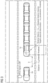
- FIG 3 shows schematically a possible traffic scenario for illustrating the operation of a method and system according to the present invention.
- the RPCS rear pre-crash safety system 1 of the subject vehicle SV can judge whether a warning is necessary using a time TTC it takes for a collision to occur between the subject vehicle SV and the target vehicle TV.
- Target vehicles TV that are very close to a subject vehicle SV which travels at a considerable low speed V SV do not pose a critical threat anymore.
- the judgement logic 2 can suppress the RPCS warning signal in this traffic scenario.
- the judgement logic 2 of the rear pre-crash safety system 1 does suppress the RPCS warning signal since the approaching target vehicle TV does no longer pose a threat to the subject vehicle SV.
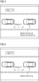
- Figures 4, 5 show schematically further specific traffic scenarios which are recognized by the judgement logic 2 to suppress an unwanted RPCS warning signal.
- the judgement logic 2 of the rear pre-crash safety system 1 can compute a time to collision, TTC, of the target vehicle TV to collide with the subject vehicle SV.
- TTC time to collision
- TTC it is possible to use a relative acceleration, a current distance and a relative velocity between the subject vehicle SV and the target vehicle TV.
- usage of a relative acceleration a R when both the subject vehicle SV and target vehicle TV are moving can lead to a wrong value of the time to collision, TTC.
- the TTC can be computed using two different modes.
- the judgement logic 2 computes the time to collision, TTC, depending on three factors including the relative velocity V R , the relative acceleration a R and the current distance D between the subject vehicle SV and the target vehicle TV.
- TTC TTC V R , a R , D
- the judgement logic 2 is adapted to compute the time to collision, TTC, using a basic computation and evaluating only the relative velocity V R and the current distance D between the subject vehicle SV and the target vehicle TV.
- TTC TTC V R , D
- Figure 7 shows schematically a further traffic scenario detected by the judgement logic 2 having an impact on the triggering of the RPCS warning signal.
- a strong brake i.e. if the negative acceleration of the subject vehicle SV is increased and if the target vehicle TV simultaneously applies a sufficient amount of braking force to avoid a collision with the subject vehicle SV
- the target vehicle TV also changes a lane from the subject lane of the subject vehicle SV to an adjacent lane, this may still trigger unwanted an RPCS warning signal in a conventional system.
Landscapes
- Engineering & Computer Science (AREA)
- Radar, Positioning & Navigation (AREA)
- Remote Sensing (AREA)
- Physics & Mathematics (AREA)
- Mechanical Engineering (AREA)
- General Physics & Mathematics (AREA)
- Computer Networks & Wireless Communication (AREA)
- Electromagnetism (AREA)
- Human Computer Interaction (AREA)
- Traffic Control Systems (AREA)
Description
- The invention relates to a rear pre-crash safety system, RPCS, of a subject vehicle, in particular a car.
- A wide range of conventional technologies has been proposed to ensure the safety of passengers of a vehicle. The focus of passive safety systems has been to design a car body which is adapted to absorb a potentially high energy which is generated by a collision with another object such as a target vehicle approaching the subject vehicle. These kinds of passive safety systems comprise for instance seat belts and airbags. Increasingly, advanced active pre-crash safety systems are used in vehicles. With these active safety systems, other vehicles, obstacles, pedestrians or any other kinds of objects in the vehicle's path and/or vehicle's vicinity can be detected to trigger a reaction of the subject vehicle, in particular to avoid a collision with the other object, in particular a target vehicle approaching the subject vehicle. The rear pre-crash safety system can use a radar signal reflected by another object or a target vehicle approaching the subject vehicle from behind to trigger an activator such as a hazard light warning the driver of the approaching target vehicle. Accordingly, conventional rear pre-crash safety systems can issue warning signals in case that another object is approaching the subject vehicle from behind. However, in many scenarios unwanted rear pre-crash system, RPCS, warning signals are issued or generated by the rear pre-crash safety system.
- Document
DE 10 2008 048 436 A1 discloses a method for avoiding a collision, respectively, for reducing the severity of a crash. - Document
DE 10 2004 062 497 A1 discloses a method and apparatus for reducing the risk of a crash situation. - Document
US 2007/0152803 A1 discloses a method and an apparatus for rear-end collision warning and accident mitigation. - Document
US 2009/0312916 A1 discloses a whiplash reduction system based on a sensor arrangement for detecting a rearwardly approaching object. - Accordingly, it is an object of the present invention to provide a rear pre-crash safety system and a corresponding method to avoid unwanted RPCS warning signals. The rear pre-crash system RPCS can also be named as flashing hazard lights (FHL)
- This object is achieved according to a first aspect of the present invention by a rear pre-crash safety system comprising the features of claim 1.
- The invention provides according to the first aspect of the present invention a rear pre-crash system, RPCS, of a subject vehicle comprising a judgement logic adapted to trigger an RPCS warning signal in response to a detected radar signal reflected by a target vehicle approaching the subject vehicle from behind,
wherein said judgement logic is configured to modify the triggering of the RPCS warning signal in detected specific traffic scenarios. - In a possible embodiment of the rear pre-crash safety system according to the first aspect of the present invention, a specific traffic scenario is detected on the basis of further measured parameters comprising:
- a velocity of the subject vehicle,
- a velocity of the target vehicle,
- a relative velocity between the subject vehicle and the target vehicle,
- an acceleration of the subject vehicle,
- an acceleration of the target vehicle,
- a relative acceleration between the subject vehicle and the target vehicle,
- a current distance between the subject vehicle and the target vehicle and/or
- a corridor occupancy of the target vehicle.
- According to the invention, if the current distance of the target vehicle is smaller than a current distance threshold (D < DTH) and the relative velocity between the subject vehicle and the target vehicle (VR) is smaller than a predetermined velocity threshold value (VR < VRTH) and if the acceleration of the target vehicle is smaller than a threshold acceleration (aTV < aTH), the judgement logic of the rear pre-crash safety system is adapted to suppress a RPCS warning signal.
- In a further possible embodiment of the rear pre-crash safety system according to the first aspect of the present invention, the judgement logic of the rear pre-crash safety system is configured to compute a time to collision, TTC, for the target vehicle to collide with the subject vehicle.
- In a still further possible embodiment of the rear pre-crash safety system according to the first aspect of the present invention, the judgement logic of the rear pre-crash safety system is configured to compute the time to collision, TTC, in a first mode if the velocity of the subject vehicle is smaller or equal to zero (VSv ≤ 0) depending on the relative velocity (VR), the relative acceleration (aR) and the current distance (D) and is further configured to compute the time to collision, TTC, in a second mode if the velocity of the subject vehicle is higher than zero (VSv > 0) only depending on the relative velocity (VR) and the current distance (D) between the subject vehicle and the target vehicle.
- In a further possible embodiment of the rear pre-crash safety system according to the first aspect of the present invention, at least one radar sensor device connected to said judgement logic is provided at a rear bumper of the subject vehicle and adapted to detect a radar signal reflected by a target vehicle approaching the subject vehicle from behind. In a still further possible embodiment of the rear pre-crash safety system according to the first aspect of the present invention, a left radar sensor device connected to the judgement logic is provided at a left side of a rear bumper of the subject vehicle and a right radar sensor device is provided at a right side of a rear bumper of the subject vehicle having overlapping field of views, FOVs, to detect radar signals reflected by a target vehicle approaching the subject vehicle from behind.
- In a further possible embodiment of the rear pre-crash safety system according to the first aspect of the present invention, the judgement logic of the rear pre-crash safety system is configured to issue an RPCS warning signal if a corridor occupancy of an approaching target vehicle occupying a corridor between corridor lines of a subject lane of the subject vehicle exceeds an adjustable corridor occupancy threshold value.
- In a further possible embodiment of the rear pre-crash safety system according to the first aspect of the present invention, the corridor occupancy of a target vehicle is monitored by the judgement logic depending on reflected radar signals detected by a left radar sensor device and by a right radar sensor device provided at a rear bumper of the subject vehicle.
- In a still further possible embodiment of the rear pre-crash safety system according to the first aspect of the present invention, the corridor occupancy threshold value is automatically increased if the monitored corridor occupancy has a considerably high overlap with a lane adjacent to the subject lane of the subject vehicle.
- In a still further possible embodiment of the rear pre-crash safety system according to the first aspect of the present invention, the judgement logic of the rear pre-crash safety system is configured to suppress the RPCS warning signal if a current acceleration of the target vehicle is less than the previously detected acceleration of the target vehicle (aTVi+1 < aTVi) and
- the velocity of the subject vehicle is less than a threshold velocity (VSV < VTH) and if
- a current acceleration of the subject vehicle is higher than the previously detected acceleration of the subject vehicle (aSVi+1 > aSVi)
- for a predetermined number, N, of monitoring cycles.
- The invention further provides according to a further aspect a method for providing an RPCS warning signal by a rear pre-crash safety system of a subject vehicle comprising the features of claim 11.
- The invention provides according to the second aspect of the present invention a method for providing an RPCS warning signal by a rear pre-crash system, RPCS, of a subject vehicle, the method comprising the steps of:
- detecting a radar signal reflected by a target vehicle approaching the subject vehicle from behind by at least one radar sensor device of the subject vehicle; and
- modifying a triggering of an RPCS warning signal issued by said rear pre-crash safety system of said subject vehicle in detected specific traffic scenarios.
- In a possible embodiment of the method according to the second aspect of the present invention, a specific traffic scenario is detected automatically on the basis of further measured parameters including:
- a velocity of the subject vehicle,
- a velocity of the target vehicle,
- a relative velocity between the subject vehicle and the target vehicle,
- an acceleration of the subject vehicle,
- an acceleration of the target vehicle,
- a relative acceleration between the subject vehicle and the target vehicle,
- a current distance between the subject vehicle and the target vehicle and/or
- a corridor occupancy of the target vehicle.
- In a possible embodiment of the method according to the second aspect of the present invention, the RPCS warning signal is automatically suppressed, if a current distance between the subject vehicle and the target vehicle is less than a threshold distance (D < DTH), the relative velocity between the subject vehicle and the target vehicle is less than a threshold velocity (VR < VRTH) and if the acceleration of the target vehicle is less than an acceleration threshold (aTV < aTH).
- In a further possible embodiment of the method according to the second aspect of the present invention, the RPCS warning signal is automatically suppressed, if a current acceleration of the target vehicle is less than a previously detected acceleration of the target vehicle (aTVi+1 < aTVi) and a current velocity of the subject vehicle is less than a velocity threshold (VSv < VTH) and if a currently detected acceleration of the subject vehicle is higher than a previously detected subject vehicle acceleration (aSVi+1 > aSVi), for a predetermined number, N, of monitoring cycles.
- In a further possible embodiment of the method according to the second aspect of the present invention, a time to collision, TTC, for the target vehicle to collide with the subject vehicle is computed.
- In a further possible embodiment of the method according to the second aspect of the present invention, the time to collision, TTC, is computed in a first mode if the velocity of the subject vehicle is less or equal to zero (VSV ≤ 0) depending on a relative velocity between the subject vehicle and the target vehicle, depending on a relative acceleration between the subject vehicle and target vehicle and depending on a current distance between the subject vehicle and the target vehicle, wherein the time to collision, TTC, is further calculated in a second mode if the velocity of the subject vehicle is higher than zero (VSv > 0) depending on the relative velocity between the subject vehicle and the target vehicle and depending on the current distance between the subject vehicle and the target vehicle.
- In the following, possible embodiments of the different aspects of the present invention are described in more detail with reference to the enclosed figures.
- Figure 1
- shows a block diagram of a possible exemplary embodiment of a rear pre-crash safety system of a subject vehicle according to a first aspect of the present invention;
- Figure 2
- shows a flowchart of a possible exemplary embodiment of a method for providing an RPCS warning signal according to the second aspect of the present invention;
- Figure 3
- shows schematically a traffic scenario for illustrating the operation of a method and system for providing an RPCS warning signal according to a possible embodiment of the present invention;
- Figures 4, 5
- illustrate schematically further traffic scenarios for explaining the operation of a method and system according to a possible embodiment of the present invention;
- Figure 6
- shows schematically a further exemplary traffic scenario illustrating a possible embodiment of a method and system according to the present invention;
- Figure 7
- shows schematically a further exemplary traffic scenario for illustrating the operation of a method and system according to a specific embodiment of the present invention.
- As can be seen in
Figure 1 , a rear pre-crash safety system 1 according to a first aspect of the present invention is implemented in a subject vehicle SV driving with a velocity VSV on a road. The subject vehicle SV can be for instance a car or truck driving on a road with a velocity VSV. - The rear pre-crash safety system 1 of the subject vehicle SV comprises in the illustrated embodiment a
judgement logic 2. Thejudgement logic 2 is adapted in the illustrated embodiment to trigger at least one RPCS warning signal in response to a detected radar signal reflected by an object approaching the subject vehicle SV from behind as illustrated inFigure 1 . The object approaching the subject vehicle SV from behind can be a target vehicle TV as shown inFigure 1 . The target vehicle TV can be a car or a truck or any other traffic participant. The target vehicle TV is moving with a velocity VTV as shown inFigure 1 . Further, the subject vehicle SV as well as the target vehicle TV can be accelerated with an acceleration aSV, aTV, respectively. Thejudgement logic 2 can trigger an RPCS warning signal in response to a detected radar signal reflected by the target vehicle TV approaching the subject vehicle SV from behind. Thejudgement logic 2 of the subject vehicle SV is configured in the illustrated embodiment to modify the triggering of the RPCS warning signal in detected specific traffic scenarios. - In the illustrated example of
Figure 1 , the approaching target vehicle TV moves with a velocity VTV towards the direction of the preceding subject vehicle SV. The relative velocity VR between the target vehicle TV and the subject vehicle SV is the difference between the velocity VSV of the subject vehicle SV and the velocity VTV of the target vehicle TV. - In a possible embodiment, the relative velocity VR of the approaching target vehicle TV can be detected by the
judgement logic 2 of the subject vehicle SV on the basis of sensor signals. In a further possible embodiment, the relative velocity VR between the approaching target vehicle TV and the moving subject vehicle SV can also be derived from the reflected radar signal. - As shown in
Figure 1 , the subject vehicle SV comprises in the illustrated embodiment at least oneradar sensor device 3 which can be installed in a possible implementation in a rear bumper of the subject vehicle SV. Theradar sensor device 3 is adapted to detect a radar signal reflected by the target vehicle TV approaching the subject vehicle SV from behind. Theradar sensor device 3 supplies the detected radar signal via a signal line 4 to thejudgement logic 2 of the rear pre-crash safety system 1. - In the illustrated embodiment of
Figure 1 , thejudgement logic 2 of the rear pre-crash safety system 1 can control at least oneactivator 5 via acontrol signal line 6. In a possible embodiment, thecontrol logic 2 can trigger automatically a control signal CRTL supplied to theactivator 5. Theactivator 5 can be in a specific embodiment for instance comprise a pre-crash headrest system. The pre-crash headrest system can be used to reduce an injury of a passenger within the subject vehicle SV. The pre-crash headrest system forming anactivator 5 can achieve this instantaneously when a rear end collision is judged as unavoidable by thejudgement logic 2 by moving the headrest forward towards the head of an occupant before the collision occurs. When thecollision judgement logic 2 detects an unavoidable collision, it may transmit a pre-crash headrest activation control signal CRTL to theheadrest control unit 5. - As illustrated in
Figure 1 , the rear pre-crash safety system 1 is adapted to trigger an RPCS warning signal in detected specific traffic scenarios. These specific traffic scenarios can be detected on the basis of measured parameters. The measured parameters can comprise in a possible embodiment a velocity VSV of the subject vehicle SV and/or a velocity VTV of the target vehicle TV. Further, the detected parameters can also include a relative velocity VR between the subject vehicle SV and the target vehicle TV. In a further possible embodiment, the further measured parameters evaluated to detect a specific traffic scenario can comprise an acceleration aSV of the subject vehicle SV and/or an acceleration aTV of the target vehicle TV. Further, the measured parameters used for detecting specific traffic scenarios can include a relative acceleration aR between the subject vehicle SV and the target vehicle TV. In a further possible embodiment, the measured parameters used for detecting a specific traffic scenario can comprise a current distance D between the subject vehicle SV and the target vehicle TV. In a still further possible embodiment, the measured parameters used for detecting a specific traffic scenario can include a corridor occupancy of the target vehicle TV. -
Figure 2 shows a flowchart of a possible exemplary embodiment of a method for providing an RPCS warning signal by a rear pre-crash safety system 1 of a subject vehicle SV according to an aspect of the present invention. - In a first step S1, a radar signal reflected by a target vehicle TV approaching a subject vehicle SV from behind is detected by at least one
radar sensor device 3 of the subject vehicle SV. - In a further step S2, the triggering of an RPCS warning signal issued by the rear pre-crash safety system 1 of the subject vehicle SV is modified in detected specific traffic scenarios.
-
Figure 3 shows schematically a possible traffic scenario for illustrating the operation of a method and system according to the present invention. The RPCS rear pre-crash safety system 1 of the subject vehicle SV can judge whether a warning is necessary using a time TTC it takes for a collision to occur between the subject vehicle SV and the target vehicle TV. Target vehicles TV that are very close to a subject vehicle SV which travels at a considerable low speed VSV do not pose a critical threat anymore. Accordingly, when the target vehicle TV reaches a certain current distance D and velocity VTV which are both considerably low and the target vehicle's absolute acceleration aTV is low indicating that the target vehicle TV has already applied a sufficient amount of braking force, then thejudgement logic 2 of the rear pre-crash safety system 1 can suppress the RPCS warning signal. - For instance, if the computed vertical current distance D (in the direction of the road lanes) between the subject vehicle SV and the approaching target vehicle TV with respect to the subject vehicle's rear bumper is less than 10 m and the relative velocity VR of the target vehicle TV with respect to the velocity of the subject vehicle SV is less than 8 m/s, then if the absolute acceleration aTV of the target vehicle TV from that point is less than -1 m/s2, the
judgement logic 2 can suppress the RPCS warning signal in this traffic scenario. Accordingly, if the current distance D is less than a distance threshold (D < DTH) and if the relative velocity VR is less than a velocity threshold value VRTH (VR < VRTH) and if additionally, the absolute acceleration aTV of the target vehicle TV is less than the absolute acceleration threshold (aTV < aTH), thejudgement logic 2 of the rear pre-crash safety system 1 does suppress the RPCS warning signal since the approaching target vehicle TV does no longer pose a threat to the subject vehicle SV. -
Figures 4, 5 show schematically further specific traffic scenarios which are recognized by thejudgement logic 2 to suppress an unwanted RPCS warning signal. In a possible embodiment, thejudgement logic 2 of the rear pre-crash safety system 1 can compute a time to collision, TTC, of the target vehicle TV to collide with the subject vehicle SV. To compute the time to collision, TTC, it is possible to use a relative acceleration, a current distance and a relative velocity between the subject vehicle SV and the target vehicle TV. However, usage of a relative acceleration aR when both the subject vehicle SV and target vehicle TV are moving can lead to a wrong value of the time to collision, TTC. Accordingly, in a possible embodiment of the rear pre-crash safety system 1, the TTC can be computed using two different modes. - In a first situation where the subject vehicle SV is in a standstill and is even moving backward (VSv ≤ 0), the
judgement logic 2 computes the time to collision, TTC, depending on three factors including the relative velocity VR, the relative acceleration aR and the current distance D between the subject vehicle SV and the target vehicle TV.
- However, if the subject vehicle SV is moving forward (VSV > 0), the
judgement logic 2 is adapted to compute the time to collision, TTC, using a basic computation and evaluating only the relative velocity VR and the current distance D between the subject vehicle SV and the target vehicle TV.
- In a possible embodiment, the
judgement logic 2 comprises a switching function to switch between the two computation modes. The TTC value is calculated in different modes depending on the detected speed or velocity VSV of the subject vehicle SV. If the subject vehicle speed VSV is less than or equal to 0 m/s (VSV ≤ 0), the TTC computation applied by thejudgement logic 2 considers the relative acceleration aR between the subject vehicle SV and the target vehicle TV. However, if the velocity VSV of the subject vehicle SV is greater than 0 m/s (VSV > 0), the TTC computation performed by thejudgement logic 2 comprises a basic computation calculating the TTC only depending on the current distance D and the relative velocity VR between the subject vehicle SV and the target vehicle TV. -
Figure 4 illustrates a situation where the subject speed or velocity VSV of the subject vehicle SV is less or equal to zero (VSv ≤ 0) wherein the TTC is calculated automatically depending on the current distance D between the subject vehicle SV and the target vehicle TV, the relative velocity VR between the subject vehicle and the target vehicle TV and depending on the relative acceleration aR. -
Figure 5 shows another traffic scenario where the subject vehicle's speed is higher than zero (VSV > 0), wherein the TTC is calculated by thejudgement logic 2 only depending on the current distance D between the subject vehicle SV and the target vehicle TV and depending on the relative velocity VR between the subject vehicle SV and the target vehicle TV. -
Figure 6 illustrates a further traffic scenario. The subject vehicle SV comprises in a possible embodiment a rear bumper having at least oneradar sensor device 3 adapted to detect a radar signal reflected by a target vehicle TV approaching the subject vehicle SV from behind. In a preferred embodiment, a left radar sensor device is provided at a left side of the rear bumper of the subject vehicle SV and a right radar sensor device is provided at a right side of the rear bumper of the subject vehicle SV. The left and right radar sensor devices have overlapping field of views, FoV, to detect radar signals reflected by at least one target vehicle TV approaching the subject vehicle SV from behind. Since the left and right sensor objects are independent to each other, there is a possibility that the sensor's object might overlap or traverse to the opposite sensor's field of view, FOV. Occurrences of this traffic scenario are possible when a wide or broad target vehicle TV does change from a subject lane of the subject vehicle SV to either of the adjacent lanes as illustrated inFigure 6 . Since the left radar sensor device provides sensor signals independent to the values of the right radar sensor device, checking of an RPCS corridor occupancy of the objects can be considered. Objects or target vehicles TV that overlap more to the opposite sensor side must increase a corridor occupancy threshold that must be achieved in order to issue an RPCS warning signal by thejudgement logic 2. Thejudgement logic 2 is configured to issue an RPCS warning signal if a corridor occupancy of an approaching target vehicle TV occupying a corridor between corridor lines of a subject lane of the subject vehicle SV exceeds an adjustable corridor occupancy threshold. For instance, the corridor occupancy threshold can have a value of 0.35 as also illustrated inFigure 6 . Additionally, all RPCS objects can comprise a corridor occupancy threshold of 0.35. However, this initial corridor occupancy threshold value is adjusted dynamically accordingly to analyze sensor objects. The left sensor device objects are analyzed as follows. If the approaching object dimension has a considerably high overlap to the right side RPCS corridor line, the corridor occupancy threshold is automatically increased. The same analysis is performed to right sensor objects. The corridor occupancy of a target vehicle TV can be monitored by thejudgement logic 2 depending on reflected radar signals detected by a left radar sensor device and by a right radar sensor device provided at a rear bumper of the subject vehicle SV. The corridor occupancy threshold value is automatically increased if the monitored corridor occupancy has a considerably high overlap with a lane adjacent to the subject lane of the subject vehicle SV as illustrated inFigure 6 . -
Figure 7 shows schematically a further traffic scenario detected by thejudgement logic 2 having an impact on the triggering of the RPCS warning signal. When the subject vehicle SV suddenly applies a strong brake, i.e. if the negative acceleration of the subject vehicle SV is increased and if the target vehicle TV simultaneously applies a sufficient amount of braking force to avoid a collision with the subject vehicle SV, then, if the target vehicle TV also changes a lane from the subject lane of the subject vehicle SV to an adjacent lane, this may still trigger unwanted an RPCS warning signal in a conventional system. Accordingly, in a preferred embodiment of the rear pre-crash safety system 1 according to the present invention, thejudgement logic 2 is configured to suppress the RPCS warning signal in such a traffic situation where a current acceleration of a target vehicle aTVi+1 is less than a previously detected acceleration of target vehicle (aTVi+1 < aTVi) and if the subject vehicle speed VSV is less than a predetermined velocity threshold value (VSv < VTH), and if further, an acceleration of the subject vehicle SV has increased (aSVi+1 > aSVi) and if these three conditions are met continuously for a predetermined number, N, of monitoring cycles. Looking at the properties of the target vehicle TV in this specific traffic scenario as shown inFigure 7 , the continuous decrease of the target vehicle's acceleration, subject vehicle's speed and acceleration provides a unique behavior. In order to suppress an unwanted RPCS warning signal, three conditions are checked by thejudgement logic 2 to suppress an RPCS warning signal. The first condition is that the target vehicle acceleration aTV is decreased from the last cycle's value. The second condition is that the subject vehicle's speed VSV is for instance less than 1 m/sec. - The third condition is that the subject vehicle's acceleration aSV is increased or remains the same as in the previous monitoring cycle. If these three conditions are met continuously, the
judgement logic 2 automatically does suppress an RPCS warning signal. - Further embodiments of the rear pre-crash safety system 1 according to the present invention are possible. For instance, in a possible embodiment, if a radar cross section RCS of the approaching target vehicle TV and/or the relative velocity VR of the approaching target vehicle TV are below configurable threshold values, the RPCS warning signal can be suppressed by this
judgement logic 2. As in a stop-and-go traffic situation, the radar cross section RCS of a following target vehicle TV following the subject vehicle SV from behind can be kept in a standstill condition and can be refreshed whenever a velocity of the following target vehicle TV relative to the subject vehicle SV is detected. In such a stop-and-go traffic situation or scenario, the RPCS warning signal can be suppressed by thejudgement logic 2 in response to a detected radar signal reflected by a further target object besides the following target object approaching the vehicle from behind. In a still further possible embodiment, an object or a target vehicle TV approaching the subject vehicle SV from behind can be classified by thejudgement logic 2 depending on a radar cross section RCS of the approaching target vehicle TV and/or a relative velocity of the approaching target vehicle TV. In a possible embodiment, the approaching target vehicle TV can comprise a traffic participant including a truck, a car, a motorbike, a bicycle and/or a pedestrian.
Claims (14)
- A rear pre-crash system, RPCS, of a subject vehicle (SV) comprising a judgement logic (2) adapted to trigger an RPCS warning signal in response to a detected radar signal reflected by a target vehicle (TV) approaching the subject vehicle (SV) from behind,
wherein said judgement logic (2) is configured to modify the triggering of the RPCS warning signal in detected specific traffic scenarios, characterized in that the judgement logic (2) is adapted to suppress the RPCS warning signal, if the distance between the subject vehicle (SV) and the target vehicle (TV) is smaller than a threshold distance (D < DTH) and the relative velocity (VR) is smaller than a threshold relative velocity (VR < VRTH) and if the acceleration (aTV) of the target vehicle (TV) is smaller than a threshold acceleration (aTV < aTH). - The rear pre-crash system according to claim 1 wherein a specific traffic scenario is detected on the basis of further measured parameters comprising:- a velocity (VSV) of the subject vehicle,- a velocity (VST) of the target vehicle,- a relative velocity (VR) between the subject vehicle and the target vehicle,- an acceleration (asv) of the subject vehicle,- an acceleration (aTV) of the target vehicle,- a relative acceleration (aR) between the subject vehicle and the target vehicle,- a current distance (D) between the subject vehicle and the target vehicle and/or- a corridor occupancy of the target vehicle.
- The rear pre-crash system according to any of the preceding claims 1 to 3 wherein the judgement logic (2) is configured to compute a time to collision, TTC, for the target vehicle (TV) to collide with the subject vehicle (SV) .
- The rear pre-crash system according to claim 3 wherein the judgement logic (2) is configured to compute the time to collision, TTC, ina first mode if the velocity of the subject vehicle is less than or equal to zero (VSv ≤ 0) depending on the relative velocity (VR) between the subject vehicle (SV) and the target vehicle (TV), the relative acceleration (aR) and the distance (D) between the subject vehicle (SV) and the target vehicle (TV), andwherein the judgement logic (2) is further configured to compute the time to collision, TTC, in a second mode if the velocity of the subject vehicle (SV) is more than zero (VSV > 0) depending on a relative velocity (VR) between the subject vehicle (SV) and the target vehicle (TV) and depending on the current distance (D) between the subject vehicle (SV) and the target vehicle (TV).
- The rear pre-crash system according to any of the preceding claims 1 to 5 wherein connected to said judgement logic (2) at least one radar sensor device (3) is provided at a rear bumper of the subject vehicle (SV) and adapted to detect a radar signal reflected by a target vehicle (TV) approaching the subject vehicle (SV) from behind.
- The rear pre-crash system according to claim 5 wherein connected to said judgement logic (2) a left radar sensor device is provided at a left side of a rear bumper of the subject vehicle (SV) and a right radar sensor device is provided at a right side of a rear bumper of the subject vehicle (SV) having overlapping field of views, FOVs, to detect radar signals reflected by a target vehicle (TV) approaching the subject vehicle (SV) from behind.
- The rear pre-crash system according to any of the preceding claims 1 to 6 wherein the judgement logic (2) is configured to issue a RPCS warning signal if a corridor occupancy of an approaching target vehicle (TV) occupying a corridor between corridor lines of a subject lane of the subject vehicle (SV) exceeds an adjustable corridor occupancy threshold value.
- The rear pre-crash system according to claim 7 wherein the corridor occupancy of a target vehicle (TV) is monitored by said judgement logic (2) depending on reflected radar signals detected by a left radar sensor device and by a right radar sensor device provided at a rear bumper of the subject vehicle (SV).
- The rear pre-crash system according to any of the preceding claims 7 to 8 wherein the corridor occupancy threshold value is automatically increased if the monitored corridor occupancy has a considerably high overlap with a lane adjacent to the subject lane of the subject vehicle (SV) .
- The rear pre-crash system according to any of the preceding claims 1 to 9 wherein the judgement logic (2) is configured to suppress the RPCS warning signal if an acceleration of the target vehicle (TV) has decreased from the last cycles value (aTVi+1 < aTVi) and if the velocity of the subject vehicle (SV) is less than a threshold velocity (Vsv < VTH) and
an acceleration of the subject vehicle (SV) has increased or remains the same as in a previous cycle (asvi+i > asvi) for a predetermined number, N, of monitoring cycles. - A method for providing an RPCS warning signal by a rear pre-crash system, RPCS, (1) of a subject vehicle (SV), the method comprising the steps of:(a) detecting (S1) a radar signal reflected by a target vehicle (TV) approaching the subject vehicle (SV) from behind by at least one radar sensor device (3) of the subject vehicle (SV); and(b) modifying (S2) the triggering of a RPCS warning signal issued by said rear pre-crash system, RPCS, (1) of said subject vehicle (SV) in detected specific traffic scenarios;characterized in that the RPCS warning signal is automatically suppressed, if the current distance (D) between the subject vehicle (SV) and the target vehicle (TV) is less than a threshold distance (D < DTH), the relative velocity (VR) between the subject vehicle (SV) and the target vehicle (TV) is less than a relative threshold velocity (VR < VRTH) and if the acceleration of the target vehicle (TV) is less than a threshold acceleration (aTV < aTH).
- The method according to claim 11 wherein a specific traffic scenario is detected on the basis of further measured parameters comprising- a velocity (VSV) of the subject vehicle,- a velocity (VST) of the target vehicle,- a relative velocity (VR) between the subject vehicle and the target vehicle,- an acceleration (asv) of the subject vehicle,- an acceleration (aTV) of the target vehicle,- a relative acceleration (aR) between the subject vehicle and the target vehicle,- a current distance (D) between the subject vehicle and the target vehicle and/or- a corridor occupancy of the target vehicle.
- The method according to claim 11 or 12 wherein the RPCS warning signal is automatically suppressed,
if the current acceleration of the target vehicle (TV) is less than the acceleration of the target vehicle (TV) in the previous cycle (aTVi+1 < aTVi) and the velocity of the subject vehicle (SV) is less than a threshold velocity (VSV < VTH) and the current acceleration of the subject vehicle (SV) is higher than the acceleration of the subject vehicle (SV) in the previous cycle (asvi+i > asvi) for a predetermined number, N, of monitoring cycles. - The method according to any of the preceding claims 11 to 13 wherein a time to collision, TTC, for the target vehicle (TV) to collide with the subject vehicle (SV) is computed when the time to collision, TTC, is computed in a first mode if the velocity (VSV) of the subject vehicle (SV) is equal to or less than zero (VSV ≤ 0) depending on a relative velocity (VR) between the subject vehicle (SV) and the target vehicle (TV), and a relative acceleration (aR) between the acceleration (asv) of the subject vehicle (SV) and the acceleration (aTV) of the target vehicle (TV) and depending on a current distance (D) between the subject vehicle (SV) and the target vehicle (TV), and
wherein the time to collision, TTC, is calculated in a second mode if the velocity (VSV) of the subject vehicle (SV) is higher than zero (VSV > 0) only depending on the relative velocity (VR) between the subject vehicle (SV) and the target vehicle (TV) and depending on a current distance (D) between the subject vehicle (SV) and the target vehicle (TV).
Applications Claiming Priority (1)
| Application Number | Priority Date | Filing Date | Title |
|---|---|---|---|
| PCT/EP2017/064316 WO2018228666A1 (en) | 2017-06-12 | 2017-06-12 | A rear pre-crash safety system |
Publications (3)
| Publication Number | Publication Date |
|---|---|
| EP3638547A1 EP3638547A1 (en) | 2020-04-22 |
| EP3638547B1 true EP3638547B1 (en) | 2024-07-10 |
| EP3638547B8 EP3638547B8 (en) | 2024-10-09 |
Family
ID=59093540
Family Applications (2)
| Application Number | Title | Priority Date | Filing Date |
|---|---|---|---|
| EP17731837.5A Active EP3638547B8 (en) | 2017-06-12 | 2017-06-12 | A rear pre-crash safety system |
| EP17751413.0A Active EP3638548B8 (en) | 2017-06-12 | 2017-08-11 | Rear pre-crash flashing hazard lamp system |
Family Applications After (1)
| Application Number | Title | Priority Date | Filing Date |
|---|---|---|---|
| EP17751413.0A Active EP3638548B8 (en) | 2017-06-12 | 2017-08-11 | Rear pre-crash flashing hazard lamp system |
Country Status (6)
| Country | Link |
|---|---|
| US (2) | US11618380B2 (en) |
| EP (2) | EP3638547B8 (en) |
| JP (2) | JP6983915B2 (en) |
| CN (2) | CN110799383B (en) |
| DE (2) | DE112017007636T5 (en) |
| WO (2) | WO2018228666A1 (en) |
Families Citing this family (9)
| Publication number | Priority date | Publication date | Assignee | Title |
|---|---|---|---|---|
| CN114291099B (en) * | 2020-03-03 | 2024-05-31 | 北京百度网讯科技有限公司 | Parking method and device for autonomous driving vehicle |
| KR20210150921A (en) * | 2020-06-04 | 2021-12-13 | 현대모비스 주식회사 | System and method for safety driving control of vehicle |
| US11488467B1 (en) | 2020-09-02 | 2022-11-01 | Wm Intellectual Property Holdings, L.L.C. | System and method for oncoming vehicle detection and alerts for a waste collection vehicle |
| US20220187447A1 (en) * | 2020-12-11 | 2022-06-16 | Continental Automotive Systems, Inc. | Imaging sensor air shield |
| TWI771094B (en) * | 2021-07-05 | 2022-07-11 | 為升電裝工業股份有限公司 | Pedal with anti-collision detection and radar installation space |
| CN116400347B (en) * | 2021-12-09 | 2026-04-21 | 本田技研工业株式会社 | Vehicle body structure condition assessment device and method |
| WO2023208442A1 (en) | 2022-04-29 | 2023-11-02 | Zf Cv Systems Global Gmbh | Method for operating an advanced emergency braking system |
| CN114994654B (en) * | 2022-05-26 | 2025-03-25 | 上海海拉电子有限公司 | Method and system for suppressing false alarm caused by false targets |
| EP4357807A1 (en) | 2022-10-19 | 2024-04-24 | Continental Autonomous Mobility Germany GmbH | Vehicle detection system and method for detecting a target vehicle in a detection area located behind a subject vehicle |
Citations (3)
| Publication number | Priority date | Publication date | Assignee | Title |
|---|---|---|---|---|
| US20070152803A1 (en) * | 2005-12-28 | 2007-07-05 | Quinfeng Huang | Method and apparatus for rear-end collision warning and accident mitigation |
| US20090312916A1 (en) * | 2008-06-13 | 2009-12-17 | Rao Manoharprasad K | Low cost whiplash reduction system |
| DE102008048436A1 (en) * | 2008-09-23 | 2010-03-25 | Daimler Ag | Method for avoiding collision or reducing severity of collision during rear-end collision accident on rear end of one vehicle by another vehicle, involves determining distance and relative velocity between two vehicles |
Family Cites Families (37)
| Publication number | Priority date | Publication date | Assignee | Title |
|---|---|---|---|---|
| US5732785A (en) | 1996-03-28 | 1998-03-31 | Transmart Technologies, Inc. | Proactive exterior airbag system and its deployment method for a motor vehicle |
| US5646613A (en) | 1996-05-20 | 1997-07-08 | Cho; Myungeun | System for minimizing automobile collision damage |
| US6025796A (en) | 1996-12-09 | 2000-02-15 | Crosby, Ii; Robert G. | Radar detector for pre-impact airbag triggering |
| EP1345044A1 (en) | 2000-02-08 | 2003-09-17 | Cambridge Consultants Limited | Methods and apparatus for obtaining positional information |
| JP4152061B2 (en) | 2000-05-15 | 2008-09-17 | 日産自動車株式会社 | Vehicle occupant restraint system |
| US6906621B2 (en) | 2001-02-06 | 2005-06-14 | Mazda Motor Corporation | Occupant protection system for vehicle |
| JP2003090877A (en) | 2001-07-12 | 2003-03-28 | Murata Mfg Co Ltd | Radar device |
| US6873911B2 (en) | 2002-02-01 | 2005-03-29 | Nissan Motor Co., Ltd. | Method and system for vehicle operator assistance improvement |
| JP4014938B2 (en) | 2002-06-06 | 2007-11-28 | 本田技研工業株式会社 | Vehicle occupant protection device |
| DE10344617A1 (en) | 2003-09-25 | 2005-05-04 | Bosch Gmbh Robert | Method for determining measurement properties of a radar sensor device of a motor vehicle |
| US7702425B2 (en) | 2004-06-07 | 2010-04-20 | Ford Global Technologies | Object classification system for a vehicle |
| US20060091654A1 (en) | 2004-11-04 | 2006-05-04 | Autoliv Asp, Inc. | Sensor system with radar sensor and vision sensor |
| DE102004062497B4 (en) | 2004-12-24 | 2016-05-19 | Daimler Ag | Method and device for reducing the risk of a rear-end collision |
| DE102005062274A1 (en) * | 2005-12-24 | 2007-06-28 | Daimlerchrysler Ag | Detection process for impending rear-end impact has delay factor applied to second vehicle, such as relative delay or inherent delay of second vehicle |
| JP4661602B2 (en) | 2006-01-13 | 2011-03-30 | トヨタ自動車株式会社 | Rear vehicle analysis device and collision prediction device |
| GB2436916B (en) | 2006-03-29 | 2008-09-24 | John Turnbull | Warning System |
| DE102007045960B3 (en) | 2007-09-26 | 2009-04-16 | Daimler Ag | Method and device for warning subsequent vehicles in frontal escalating longitudinal traffic |
| JP2009198402A (en) | 2008-02-22 | 2009-09-03 | Toyota Motor Corp | Impact detection device |
| US8060280B2 (en) | 2008-04-15 | 2011-11-15 | Autoliv Asp, Inc. | Vision system for deploying safety systems |
| JP4843003B2 (en) | 2008-08-05 | 2011-12-21 | 富士通テン株式会社 | Signal processing apparatus, radar apparatus, and signal processing method |
| DE112008004072B4 (en) * | 2008-12-05 | 2013-11-07 | Toyota Jidosha Kabushiki Kaisha | PRE-CRASH SAFETY SYSTEM |
| JP2011037308A (en) | 2009-08-06 | 2011-02-24 | Aisin Seiki Co Ltd | Vehicular occupant protection system |
| JP5455602B2 (en) | 2009-12-16 | 2014-03-26 | Udトラックス株式会社 | Collision damage reduction device |
| JP4964321B2 (en) | 2010-04-16 | 2012-06-27 | 三菱電機株式会社 | Crew protection device |
| JP5583523B2 (en) | 2010-08-31 | 2014-09-03 | ダイハツ工業株式会社 | Object recognition device |
| JP5811543B2 (en) | 2011-02-15 | 2015-11-11 | トヨタ自動車株式会社 | Rear vehicle collision warning device |
| DE102012017669A1 (en) | 2012-09-07 | 2014-03-13 | Valeo Schalter Und Sensoren Gmbh | Arrangement with a trim part and a radar sensor, motor vehicle and method for producing an arrangement |
| US9437111B2 (en) | 2014-05-30 | 2016-09-06 | Ford Global Technologies, Llc | Boundary detection system |
| WO2016024316A1 (en) | 2014-08-11 | 2016-02-18 | 日産自動車株式会社 | Travel control device and method for vehicle |
| EP3021134B1 (en) | 2014-11-13 | 2020-06-03 | Veoneer Sweden AB | Sensor handover |
| CN104515990B (en) | 2014-12-18 | 2017-02-22 | 河海大学 | Automotive anti-collision radar multi-object identification method based on PRONY spectral line estimation |
| JP6115579B2 (en) | 2015-02-16 | 2017-04-19 | トヨタ自動車株式会社 | Collision avoidance device |
| JP6363558B2 (en) * | 2015-06-02 | 2018-07-25 | 株式会社デンソー | Vehicle control apparatus and vehicle control method |
| CN105667441A (en) | 2016-01-04 | 2016-06-15 | 重庆长安汽车股份有限公司 | Rear-end collision preventing safety system and method with early warning and protecting functions |
| CN106240458B (en) * | 2016-07-22 | 2017-12-12 | 浙江零跑科技有限公司 | A kind of vehicular frontal impact method for early warning based on vehicle-mounted binocular camera |
| CN206086597U (en) | 2016-08-03 | 2017-04-12 | 安徽工程大学 | Independently with car system |
| US20190011547A1 (en) | 2017-07-07 | 2019-01-10 | Veoneer Us, Inc. | Systems and methods for resolving velocity ambiguity in an automotive radar system |
-
2017
- 2017-06-12 JP JP2019569681A patent/JP6983915B2/en active Active
- 2017-06-12 US US16/621,429 patent/US11618380B2/en active Active
- 2017-06-12 WO PCT/EP2017/064316 patent/WO2018228666A1/en not_active Ceased
- 2017-06-12 EP EP17731837.5A patent/EP3638547B8/en active Active
- 2017-06-12 CN CN201780091990.6A patent/CN110799383B/en active Active
- 2017-06-12 DE DE112017007636.6T patent/DE112017007636T5/en not_active Withdrawn
- 2017-08-11 US US16/621,598 patent/US10994654B2/en not_active Expired - Fee Related
- 2017-08-11 WO PCT/EP2017/070486 patent/WO2018228711A1/en not_active Ceased
- 2017-08-11 EP EP17751413.0A patent/EP3638548B8/en active Active
- 2017-08-11 CN CN201780091943.1A patent/CN110869247B/en active Active
- 2017-08-11 DE DE112017007635.8T patent/DE112017007635T5/en not_active Withdrawn
- 2017-08-11 JP JP2019569680A patent/JP6941190B2/en active Active
Patent Citations (3)
| Publication number | Priority date | Publication date | Assignee | Title |
|---|---|---|---|---|
| US20070152803A1 (en) * | 2005-12-28 | 2007-07-05 | Quinfeng Huang | Method and apparatus for rear-end collision warning and accident mitigation |
| US20090312916A1 (en) * | 2008-06-13 | 2009-12-17 | Rao Manoharprasad K | Low cost whiplash reduction system |
| DE102008048436A1 (en) * | 2008-09-23 | 2010-03-25 | Daimler Ag | Method for avoiding collision or reducing severity of collision during rear-end collision accident on rear end of one vehicle by another vehicle, involves determining distance and relative velocity between two vehicles |
Also Published As
| Publication number | Publication date |
|---|---|
| EP3638548B8 (en) | 2024-05-01 |
| US11618380B2 (en) | 2023-04-04 |
| CN110799383A (en) | 2020-02-14 |
| JP2020523708A (en) | 2020-08-06 |
| DE112017007635T5 (en) | 2020-09-24 |
| JP2020523709A (en) | 2020-08-06 |
| WO2018228711A1 (en) | 2018-12-20 |
| EP3638547A1 (en) | 2020-04-22 |
| DE112017007636T5 (en) | 2020-09-24 |
| EP3638548A1 (en) | 2020-04-22 |
| EP3638548B1 (en) | 2024-03-27 |
| US20200207269A1 (en) | 2020-07-02 |
| EP3638547B8 (en) | 2024-10-09 |
| JP6983915B2 (en) | 2021-12-17 |
| JP6941190B2 (en) | 2021-09-29 |
| CN110799383B (en) | 2022-07-29 |
| WO2018228666A1 (en) | 2018-12-20 |
| US10994654B2 (en) | 2021-05-04 |
| US20200172011A1 (en) | 2020-06-04 |
| CN110869247A (en) | 2020-03-06 |
| CN110869247B (en) | 2022-02-11 |
Similar Documents
| Publication | Publication Date | Title |
|---|---|---|
| EP3638547B1 (en) | A rear pre-crash safety system | |
| CN104960509B (en) | For minimizing the method that automatic braking is invaded and harassed based on collision confidence level | |
| EP2484573B1 (en) | Method for reducing the risk of a collision between a vehicle and a first external object | |
| US10315650B2 (en) | Control system and control method for determining a probability of an imminent collision of a vehicle | |
| US9056615B2 (en) | Vehicle system for control of vehicle safety parameters, a vehicle and a method for controlling safety parameters | |
| US11560108B2 (en) | Vehicle safety system and method implementing weighted active-passive crash mode classification | |
| JP5278776B2 (en) | Object detection apparatus and object detection method | |
| EP2302412A1 (en) | System and method for evaluation of an automotive vehicle forward collision threat | |
| US8301336B2 (en) | Method and apparatus for warning following vehicles of frontally escalating longitudinal traffic | |
| US8855866B2 (en) | Rear end advanced collision technology | |
| CN104765030A (en) | Vehicle control apparatus and vehicle | |
| US20140207339A1 (en) | Motor vehicle safety arrangement and method | |
| US11436878B2 (en) | Method for determining the severity of a possible collision between a motor vehicle and another vehicle, control apparatus, driver assistance system and a motor vehicle | |
| US8442726B2 (en) | Method and device for lessening the consequences of an accident on a vehicle occupant | |
| JP2015205648A (en) | Collision avoidance support device | |
| KR20130013997A (en) | Apparatus for preventing car collision and method thereof | |
| CN104875730A (en) | Vehicle automatic brake device and method thereof | |
| CN112622812A (en) | Control device and control method for automobile safety belt and vehicle | |
| KR101596995B1 (en) | Impact absorption method for vehicles | |
| KR20250016923A (en) | Impcat relief apparatus by vehicle collision and method for controlling accordingly | |
| KR20210066982A (en) | Auto hold controlling apparatus to alleviate rear collision of vehicle |
Legal Events
| Date | Code | Title | Description |
|---|---|---|---|
| STAA | Information on the status of an ep patent application or granted ep patent |
Free format text: STATUS: UNKNOWN |
|
| STAA | Information on the status of an ep patent application or granted ep patent |
Free format text: STATUS: THE INTERNATIONAL PUBLICATION HAS BEEN MADE |
|
| PUAI | Public reference made under article 153(3) epc to a published international application that has entered the european phase |
Free format text: ORIGINAL CODE: 0009012 |
|
| STAA | Information on the status of an ep patent application or granted ep patent |
Free format text: STATUS: REQUEST FOR EXAMINATION WAS MADE |
|
| 17P | Request for examination filed |
Effective date: 20191209 |
|
| AK | Designated contracting states |
Kind code of ref document: A1 Designated state(s): AL AT BE BG CH CY CZ DE DK EE ES FI FR GB GR HR HU IE IS IT LI LT LU LV MC MK MT NL NO PL PT RO RS SE SI SK SM TR |
|
| AX | Request for extension of the european patent |
Extension state: BA ME |
|
| DAV | Request for validation of the european patent (deleted) | ||
| DAX | Request for extension of the european patent (deleted) | ||
| STAA | Information on the status of an ep patent application or granted ep patent |
Free format text: STATUS: EXAMINATION IS IN PROGRESS |
|
| 17Q | First examination report despatched |
Effective date: 20220613 |
|
| RAP1 | Party data changed (applicant data changed or rights of an application transferred) |
Owner name: TOYOTA JIDOSHA KABUSHIKI KAISHA Owner name: CONTINENTAL AUTOMOTIVE TECHNOLOGIES GMBH |
|
| GRAP | Despatch of communication of intention to grant a patent |
Free format text: ORIGINAL CODE: EPIDOSNIGR1 |
|
| STAA | Information on the status of an ep patent application or granted ep patent |
Free format text: STATUS: GRANT OF PATENT IS INTENDED |
|
| INTG | Intention to grant announced |
Effective date: 20240208 |
|
| RAP3 | Party data changed (applicant data changed or rights of an application transferred) |
Owner name: TOYOTA JIDOSHA KABUSHIKI KAISHA Owner name: CONTINENTAL AUTOMOTIVE TECHNOLOGIES GMBH |
|
| GRAS | Grant fee paid |
Free format text: ORIGINAL CODE: EPIDOSNIGR3 |
|
| GRAA | (expected) grant |
Free format text: ORIGINAL CODE: 0009210 |
|
| STAA | Information on the status of an ep patent application or granted ep patent |
Free format text: STATUS: THE PATENT HAS BEEN GRANTED |
|
| AK | Designated contracting states |
Kind code of ref document: B1 Designated state(s): AL AT BE BG CH CY CZ DE DK EE ES FI FR GB GR HR HU IE IS IT LI LT LU LV MC MK MT NL NO PL PT RO RS SE SI SK SM TR |
|
| REG | Reference to a national code |
Ref country code: CH Ref legal event code: EP |
|
| GRAT | Correction requested after decision to grant or after decision to maintain patent in amended form |
Free format text: ORIGINAL CODE: EPIDOSNCDEC |
|
| RAP2 | Party data changed (patent owner data changed or rights of a patent transferred) |
Owner name: TOYOTA JIDOSHA KABUSHIKI KAISHA Owner name: CONTINENTAL AUTOMOTIVE MOBILITY GERMANY GMBH |
|
| REG | Reference to a national code |
Ref country code: CH Ref legal event code: PK Free format text: BERICHTIGUNG B8 |
|
| REG | Reference to a national code |
Ref country code: DE Ref legal event code: R096 Ref document number: 602017083178 Country of ref document: DE |
|
| REG | Reference to a national code |
Ref country code: DE Ref legal event code: R081 Ref document number: 602017083178 Country of ref document: DE Owner name: TOYOTA JIDOSHA KABUSHIKI KAISHA, TOYOTA-SHI, JP Free format text: FORMER OWNERS: CONTINENTAL AUTOMOTIVE TECHNOLOGIES GMBH, 30175 HANNOVER, DE; TOYOTA JIDOSHA KABUSHIKI KAISHA, TOYOTA-SHI, AICHI-KEN, JP Ref country code: DE Ref legal event code: R081 Ref document number: 602017083178 Country of ref document: DE Owner name: CONTINENTAL AUTONOMOUS MOBILITY GERMANY GMBH, DE Free format text: FORMER OWNERS: CONTINENTAL AUTOMOTIVE TECHNOLOGIES GMBH, 30175 HANNOVER, DE; TOYOTA JIDOSHA KABUSHIKI KAISHA, TOYOTA-SHI, AICHI-KEN, JP Ref country code: DE Ref legal event code: R081 Ref document number: 602017083178 Country of ref document: DE Owner name: AUMOVIO AUTONOMOUS MOBILITY GERMANY GMBH, DE Free format text: FORMER OWNERS: CONTINENTAL AUTOMOTIVE TECHNOLOGIES GMBH, 30175 HANNOVER, DE; TOYOTA JIDOSHA KABUSHIKI KAISHA, TOYOTA-SHI, AICHI-KEN, JP |
|
| RAP4 | Party data changed (patent owner data changed or rights of a patent transferred) |
Owner name: TOYOTA JIDOSHA KABUSHIKI KAISHA Owner name: CONTINENTAL AUTONOMOUS MOBILITY GERMANY GMBH |
|
| REG | Reference to a national code |
Ref country code: CH Ref legal event code: PK Free format text: BERICHTIGUNG B8 |
|
| REG | Reference to a national code |
Ref country code: LT Ref legal event code: MG9D |
|
| REG | Reference to a national code |
Ref country code: NL Ref legal event code: MP Effective date: 20240710 |
|
| PG25 | Lapsed in a contracting state [announced via postgrant information from national office to epo] |
Ref country code: PT Free format text: LAPSE BECAUSE OF FAILURE TO SUBMIT A TRANSLATION OF THE DESCRIPTION OR TO PAY THE FEE WITHIN THE PRESCRIBED TIME-LIMIT Effective date: 20241111 |
|
| REG | Reference to a national code |
Ref country code: AT Ref legal event code: MK05 Ref document number: 1701792 Country of ref document: AT Kind code of ref document: T Effective date: 20240710 |
|
| PG25 | Lapsed in a contracting state [announced via postgrant information from national office to epo] |
Ref country code: NL Free format text: LAPSE BECAUSE OF FAILURE TO SUBMIT A TRANSLATION OF THE DESCRIPTION OR TO PAY THE FEE WITHIN THE PRESCRIBED TIME-LIMIT Effective date: 20240710 |
|
| PG25 | Lapsed in a contracting state [announced via postgrant information from national office to epo] |
Ref country code: PT Free format text: LAPSE BECAUSE OF FAILURE TO SUBMIT A TRANSLATION OF THE DESCRIPTION OR TO PAY THE FEE WITHIN THE PRESCRIBED TIME-LIMIT Effective date: 20241111 Ref country code: NL Free format text: LAPSE BECAUSE OF FAILURE TO SUBMIT A TRANSLATION OF THE DESCRIPTION OR TO PAY THE FEE WITHIN THE PRESCRIBED TIME-LIMIT Effective date: 20240710 |
|
| PG25 | Lapsed in a contracting state [announced via postgrant information from national office to epo] |
Ref country code: NO Free format text: LAPSE BECAUSE OF FAILURE TO SUBMIT A TRANSLATION OF THE DESCRIPTION OR TO PAY THE FEE WITHIN THE PRESCRIBED TIME-LIMIT Effective date: 20241010 |
|
| PG25 | Lapsed in a contracting state [announced via postgrant information from national office to epo] |
Ref country code: GR Free format text: LAPSE BECAUSE OF FAILURE TO SUBMIT A TRANSLATION OF THE DESCRIPTION OR TO PAY THE FEE WITHIN THE PRESCRIBED TIME-LIMIT Effective date: 20241011 Ref country code: PL Free format text: LAPSE BECAUSE OF FAILURE TO SUBMIT A TRANSLATION OF THE DESCRIPTION OR TO PAY THE FEE WITHIN THE PRESCRIBED TIME-LIMIT Effective date: 20240710 Ref country code: FI Free format text: LAPSE BECAUSE OF FAILURE TO SUBMIT A TRANSLATION OF THE DESCRIPTION OR TO PAY THE FEE WITHIN THE PRESCRIBED TIME-LIMIT Effective date: 20240710 |
|
| PG25 | Lapsed in a contracting state [announced via postgrant information from national office to epo] |
Ref country code: BG Free format text: LAPSE BECAUSE OF FAILURE TO SUBMIT A TRANSLATION OF THE DESCRIPTION OR TO PAY THE FEE WITHIN THE PRESCRIBED TIME-LIMIT Effective date: 20240710 |
|
| PG25 | Lapsed in a contracting state [announced via postgrant information from national office to epo] |
Ref country code: LV Free format text: LAPSE BECAUSE OF FAILURE TO SUBMIT A TRANSLATION OF THE DESCRIPTION OR TO PAY THE FEE WITHIN THE PRESCRIBED TIME-LIMIT Effective date: 20240710 |
|
| PG25 | Lapsed in a contracting state [announced via postgrant information from national office to epo] |
Ref country code: IS Free format text: LAPSE BECAUSE OF FAILURE TO SUBMIT A TRANSLATION OF THE DESCRIPTION OR TO PAY THE FEE WITHIN THE PRESCRIBED TIME-LIMIT Effective date: 20241110 Ref country code: AT Free format text: LAPSE BECAUSE OF FAILURE TO SUBMIT A TRANSLATION OF THE DESCRIPTION OR TO PAY THE FEE WITHIN THE PRESCRIBED TIME-LIMIT Effective date: 20240710 |
|
| PG25 | Lapsed in a contracting state [announced via postgrant information from national office to epo] |
Ref country code: HR Free format text: LAPSE BECAUSE OF FAILURE TO SUBMIT A TRANSLATION OF THE DESCRIPTION OR TO PAY THE FEE WITHIN THE PRESCRIBED TIME-LIMIT Effective date: 20240710 |
|
| PG25 | Lapsed in a contracting state [announced via postgrant information from national office to epo] |
Ref country code: ES Free format text: LAPSE BECAUSE OF FAILURE TO SUBMIT A TRANSLATION OF THE DESCRIPTION OR TO PAY THE FEE WITHIN THE PRESCRIBED TIME-LIMIT Effective date: 20240710 Ref country code: RS Free format text: LAPSE BECAUSE OF FAILURE TO SUBMIT A TRANSLATION OF THE DESCRIPTION OR TO PAY THE FEE WITHIN THE PRESCRIBED TIME-LIMIT Effective date: 20241010 |
|
| PG25 | Lapsed in a contracting state [announced via postgrant information from national office to epo] |
Ref country code: RS Free format text: LAPSE BECAUSE OF FAILURE TO SUBMIT A TRANSLATION OF THE DESCRIPTION OR TO PAY THE FEE WITHIN THE PRESCRIBED TIME-LIMIT Effective date: 20241010 Ref country code: PL Free format text: LAPSE BECAUSE OF FAILURE TO SUBMIT A TRANSLATION OF THE DESCRIPTION OR TO PAY THE FEE WITHIN THE PRESCRIBED TIME-LIMIT Effective date: 20240710 Ref country code: NO Free format text: LAPSE BECAUSE OF FAILURE TO SUBMIT A TRANSLATION OF THE DESCRIPTION OR TO PAY THE FEE WITHIN THE PRESCRIBED TIME-LIMIT Effective date: 20241010 Ref country code: LV Free format text: LAPSE BECAUSE OF FAILURE TO SUBMIT A TRANSLATION OF THE DESCRIPTION OR TO PAY THE FEE WITHIN THE PRESCRIBED TIME-LIMIT Effective date: 20240710 Ref country code: IS Free format text: LAPSE BECAUSE OF FAILURE TO SUBMIT A TRANSLATION OF THE DESCRIPTION OR TO PAY THE FEE WITHIN THE PRESCRIBED TIME-LIMIT Effective date: 20241110 Ref country code: HR Free format text: LAPSE BECAUSE OF FAILURE TO SUBMIT A TRANSLATION OF THE DESCRIPTION OR TO PAY THE FEE WITHIN THE PRESCRIBED TIME-LIMIT Effective date: 20240710 Ref country code: GR Free format text: LAPSE BECAUSE OF FAILURE TO SUBMIT A TRANSLATION OF THE DESCRIPTION OR TO PAY THE FEE WITHIN THE PRESCRIBED TIME-LIMIT Effective date: 20241011 Ref country code: FI Free format text: LAPSE BECAUSE OF FAILURE TO SUBMIT A TRANSLATION OF THE DESCRIPTION OR TO PAY THE FEE WITHIN THE PRESCRIBED TIME-LIMIT Effective date: 20240710 Ref country code: ES Free format text: LAPSE BECAUSE OF FAILURE TO SUBMIT A TRANSLATION OF THE DESCRIPTION OR TO PAY THE FEE WITHIN THE PRESCRIBED TIME-LIMIT Effective date: 20240710 Ref country code: BG Free format text: LAPSE BECAUSE OF FAILURE TO SUBMIT A TRANSLATION OF THE DESCRIPTION OR TO PAY THE FEE WITHIN THE PRESCRIBED TIME-LIMIT Effective date: 20240710 Ref country code: AT Free format text: LAPSE BECAUSE OF FAILURE TO SUBMIT A TRANSLATION OF THE DESCRIPTION OR TO PAY THE FEE WITHIN THE PRESCRIBED TIME-LIMIT Effective date: 20240710 |
|
| REG | Reference to a national code |
Ref country code: DE Ref legal event code: R097 Ref document number: 602017083178 Country of ref document: DE |
|
| PG25 | Lapsed in a contracting state [announced via postgrant information from national office to epo] |
Ref country code: SM Free format text: LAPSE BECAUSE OF FAILURE TO SUBMIT A TRANSLATION OF THE DESCRIPTION OR TO PAY THE FEE WITHIN THE PRESCRIBED TIME-LIMIT Effective date: 20240710 Ref country code: RO Free format text: LAPSE BECAUSE OF FAILURE TO SUBMIT A TRANSLATION OF THE DESCRIPTION OR TO PAY THE FEE WITHIN THE PRESCRIBED TIME-LIMIT Effective date: 20240710 Ref country code: DK Free format text: LAPSE BECAUSE OF FAILURE TO SUBMIT A TRANSLATION OF THE DESCRIPTION OR TO PAY THE FEE WITHIN THE PRESCRIBED TIME-LIMIT Effective date: 20240710 |
|
| PG25 | Lapsed in a contracting state [announced via postgrant information from national office to epo] |
Ref country code: CZ Free format text: LAPSE BECAUSE OF FAILURE TO SUBMIT A TRANSLATION OF THE DESCRIPTION OR TO PAY THE FEE WITHIN THE PRESCRIBED TIME-LIMIT Effective date: 20240710 |
|
| PG25 | Lapsed in a contracting state [announced via postgrant information from national office to epo] |
Ref country code: IT Free format text: LAPSE BECAUSE OF FAILURE TO SUBMIT A TRANSLATION OF THE DESCRIPTION OR TO PAY THE FEE WITHIN THE PRESCRIBED TIME-LIMIT Effective date: 20240710 Ref country code: SK Free format text: LAPSE BECAUSE OF FAILURE TO SUBMIT A TRANSLATION OF THE DESCRIPTION OR TO PAY THE FEE WITHIN THE PRESCRIBED TIME-LIMIT Effective date: 20240710 |
|
| PLBE | No opposition filed within time limit |
Free format text: ORIGINAL CODE: 0009261 |
|
| STAA | Information on the status of an ep patent application or granted ep patent |
Free format text: STATUS: NO OPPOSITION FILED WITHIN TIME LIMIT |
|
| 26N | No opposition filed |
Effective date: 20250411 |
|
| PGFP | Annual fee paid to national office [announced via postgrant information from national office to epo] |
Ref country code: DE Payment date: 20250401 Year of fee payment: 9 |
|
| REG | Reference to a national code |
Ref country code: DE Ref legal event code: R081 Ref document number: 602017083178 Country of ref document: DE Owner name: AUMOVIO AUTONOMOUS MOBILITY GERMANY GMBH, DE Free format text: FORMER OWNERS: CONTINENTAL AUTONOMOUS MOBILITY GERMANY GMBH, 85057 INGOLSTADT, DE; TOYOTA JIDOSHA KABUSHIKI KAISHA, TOYOTA-SHI, AICHI-KEN, JP Ref country code: DE Ref legal event code: R081 Ref document number: 602017083178 Country of ref document: DE Owner name: TOYOTA JIDOSHA KABUSHIKI KAISHA, TOYOTA-SHI, JP Free format text: FORMER OWNERS: CONTINENTAL AUTONOMOUS MOBILITY GERMANY GMBH, 85057 INGOLSTADT, DE; TOYOTA JIDOSHA KABUSHIKI KAISHA, TOYOTA-SHI, AICHI-KEN, JP |
|
| PGFP | Annual fee paid to national office [announced via postgrant information from national office to epo] |
Ref country code: FR Payment date: 20250626 Year of fee payment: 9 |
|
| PG25 | Lapsed in a contracting state [announced via postgrant information from national office to epo] |
Ref country code: SE Free format text: LAPSE BECAUSE OF FAILURE TO SUBMIT A TRANSLATION OF THE DESCRIPTION OR TO PAY THE FEE WITHIN THE PRESCRIBED TIME-LIMIT Effective date: 20240710 |
|
| REG | Reference to a national code |
Ref country code: CH Ref legal event code: H13 Free format text: ST27 STATUS EVENT CODE: U-0-0-H10-H13 (AS PROVIDED BY THE NATIONAL OFFICE) Effective date: 20260127 |
|
| PG25 | Lapsed in a contracting state [announced via postgrant information from national office to epo] |
Ref country code: MC Free format text: LAPSE BECAUSE OF FAILURE TO SUBMIT A TRANSLATION OF THE DESCRIPTION OR TO PAY THE FEE WITHIN THE PRESCRIBED TIME-LIMIT Effective date: 20240710 |
|
| PG25 | Lapsed in a contracting state [announced via postgrant information from national office to epo] |
Ref country code: LU Free format text: LAPSE BECAUSE OF NON-PAYMENT OF DUE FEES Effective date: 20250612 |
|
| GBPC | Gb: european patent ceased through non-payment of renewal fee |
Effective date: 20250612 |
|
| REG | Reference to a national code |
Ref country code: BE Ref legal event code: MM Effective date: 20250630 |
|
| PG25 | Lapsed in a contracting state [announced via postgrant information from national office to epo] |
Ref country code: GB Free format text: LAPSE BECAUSE OF NON-PAYMENT OF DUE FEES Effective date: 20250612 |
|
| PG25 | Lapsed in a contracting state [announced via postgrant information from national office to epo] |
Ref country code: IE Free format text: LAPSE BECAUSE OF NON-PAYMENT OF DUE FEES Effective date: 20250612 |
|
| PG25 | Lapsed in a contracting state [announced via postgrant information from national office to epo] |
Ref country code: BE Free format text: LAPSE BECAUSE OF NON-PAYMENT OF DUE FEES Effective date: 20250630 |
|
| PG25 | Lapsed in a contracting state [announced via postgrant information from national office to epo] |
Ref country code: CH Free format text: LAPSE BECAUSE OF NON-PAYMENT OF DUE FEES Effective date: 20250630 |