EP3638454B1 - Apparatus for tightening threaded fasteners - Google Patents
Apparatus for tightening threaded fasteners Download PDFInfo
- Publication number
- EP3638454B1 EP3638454B1 EP18737764.3A EP18737764A EP3638454B1 EP 3638454 B1 EP3638454 B1 EP 3638454B1 EP 18737764 A EP18737764 A EP 18737764A EP 3638454 B1 EP3638454 B1 EP 3638454B1
- Authority
- EP
- European Patent Office
- Prior art keywords
- assembly
- reaction
- drive
- fasteners
- drive extension
- Prior art date
- Legal status (The legal status is an assumption and is not a legal conclusion. Google has not performed a legal analysis and makes no representation as to the accuracy of the status listed.)
- Active
Links
Images


Classifications
-
- B—PERFORMING OPERATIONS; TRANSPORTING
- B25—HAND TOOLS; PORTABLE POWER-DRIVEN TOOLS; MANIPULATORS
- B25B—TOOLS OR BENCH DEVICES NOT OTHERWISE PROVIDED FOR, FOR FASTENING, CONNECTING, DISENGAGING, OR HOLDING
- B25B13/00—Spanners; Wrenches
- B25B13/48—Spanners; Wrenches for special purposes
- B25B13/481—Spanners; Wrenches for special purposes for operating in areas having limited access
-
- B—PERFORMING OPERATIONS; TRANSPORTING
- B25—HAND TOOLS; PORTABLE POWER-DRIVEN TOOLS; MANIPULATORS
- B25B—TOOLS OR BENCH DEVICES NOT OTHERWISE PROVIDED FOR, FOR FASTENING, CONNECTING, DISENGAGING, OR HOLDING
- B25B13/00—Spanners; Wrenches
- B25B13/02—Spanners; Wrenches with rigid jaws
- B25B13/06—Spanners; Wrenches with rigid jaws of socket type
-
- B—PERFORMING OPERATIONS; TRANSPORTING
- B25—HAND TOOLS; PORTABLE POWER-DRIVEN TOOLS; MANIPULATORS
- B25B—TOOLS OR BENCH DEVICES NOT OTHERWISE PROVIDED FOR, FOR FASTENING, CONNECTING, DISENGAGING, OR HOLDING
- B25B23/00—Details of, or accessories for, spanners, wrenches, screwdrivers
- B25B23/0007—Connections or joints between tool parts
- B25B23/0021—Prolongations interposed between handle and tool
-
- B—PERFORMING OPERATIONS; TRANSPORTING
- B25—HAND TOOLS; PORTABLE POWER-DRIVEN TOOLS; MANIPULATORS
- B25B—TOOLS OR BENCH DEVICES NOT OTHERWISE PROVIDED FOR, FOR FASTENING, CONNECTING, DISENGAGING, OR HOLDING
- B25B23/00—Details of, or accessories for, spanners, wrenches, screwdrivers
- B25B23/0007—Connections or joints between tool parts
- B25B23/0028—Angular adjustment means between tool head and handle
-
- B—PERFORMING OPERATIONS; TRANSPORTING
- B25—HAND TOOLS; PORTABLE POWER-DRIVEN TOOLS; MANIPULATORS
- B25B—TOOLS OR BENCH DEVICES NOT OTHERWISE PROVIDED FOR, FOR FASTENING, CONNECTING, DISENGAGING, OR HOLDING
- B25B23/00—Details of, or accessories for, spanners, wrenches, screwdrivers
- B25B23/0078—Reaction arms
-
- B—PERFORMING OPERATIONS; TRANSPORTING
- B60—VEHICLES IN GENERAL
- B60B—VEHICLE WHEELS; CASTORS; AXLES FOR WHEELS OR CASTORS; INCREASING WHEEL ADHESION
- B60B29/00—Apparatus or tools for mounting or dismounting wheels
-
- B—PERFORMING OPERATIONS; TRANSPORTING
- B60—VEHICLES IN GENERAL
- B60B—VEHICLE WHEELS; CASTORS; AXLES FOR WHEELS OR CASTORS; INCREASING WHEEL ADHESION
- B60B2900/00—Purpose of invention
- B60B2900/50—Improvement of
- B60B2900/541—Servicing
-
- B—PERFORMING OPERATIONS; TRANSPORTING
- B60—VEHICLES IN GENERAL
- B60Y—INDEXING SCHEME RELATING TO ASPECTS CROSS-CUTTING VEHICLE TECHNOLOGY
- B60Y2200/00—Type of vehicle
- B60Y2200/40—Special vehicles
- B60Y2200/41—Construction vehicles, e.g. graders, excavators
-
- Y—GENERAL TAGGING OF NEW TECHNOLOGICAL DEVELOPMENTS; GENERAL TAGGING OF CROSS-SECTIONAL TECHNOLOGIES SPANNING OVER SEVERAL SECTIONS OF THE IPC; TECHNICAL SUBJECTS COVERED BY FORMER USPC CROSS-REFERENCE ART COLLECTIONS [XRACs] AND DIGESTS
- Y02—TECHNOLOGIES OR APPLICATIONS FOR MITIGATION OR ADAPTATION AGAINST CLIMATE CHANGE
- Y02T—CLIMATE CHANGE MITIGATION TECHNOLOGIES RELATED TO TRANSPORTATION
- Y02T10/00—Road transport of goods or passengers
- Y02T10/80—Technologies aiming to reduce greenhouse gasses emissions common to all road transportation technologies
- Y02T10/86—Optimisation of rolling resistance, e.g. weight reduction
Definitions
- a known tightening solution 50 requires use of a reaction fixture 51 shaped like a cross with a drive shaft extension 52.
- Known solution 50 reacts off of bolt heads on each side of reaction fixture 51 of a third circumferential array of fasteners 13 quite far from fasteners 11.
- This flawed solution puts excessive strain and side load on the system due to the positioning and angle ⁇ 50 of a socket 53, reaction fixture 51 and drive extension 52.
- Reaction points 55 and 56 are removed a distance H 50 from fasteners 11.
- Substantial risk of drive shaft extension 52, tool 40 and internal tool gearing failures and reaction fixture 51 slippages are characteristic of known solution 50. See FIGs. 4-5 .
- This application discloses an apparatus 100 for use with an electrically, hydraulically and/or pneumatically driven torque tool for tightening or loosening inaccessible threaded fasteners including a drive extension assembly 110, a reaction assembly 120 and a socket assembly 130.
- the present invention uses an external reaction member which holds on to two (2) or four (4) adjacent studs while turning a fastener with an extended drive ball and socket joint connection. It more efficiently distributes/reduces the side loads and system strains from the reaction forces on the bolts by bringing the reaction point much closer to the fastener being turned. It allows for a plurality of fastener approach angles and is adaptable to a plurality of fastener obstructions. It's relatively lightweight, easy to maneuver from fastener to fastener and overall user friendly. Compared to known tightening solution 50, apparatus 100 is a stable, secure, solid and compact system with no twisting or tendency to creep or crawl of off the reaction points.
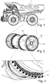
- FIG. 1 shows a side, perspective view of Komatsu 980 Mining Truck 1.
- FIG.2 shows a perspective view of five piece flange rim assemblies 10.
- FIG. 3 shows a perspective view of a portion of inner, lower circumferential array of inaccessible fasteners 11.
- FIGs. 5 and 6 show perspective views of known tightening solution 50.
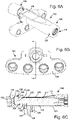
- FIGs. 6A, 6B and 6C show perspective, bottom and cross-sectional views, respectively, of apparatus 100 of the present invention.
- FIG. 7 shows a perspective view of an apparatus 200 of the present invention.
- apparatus 100 includes drive extension assembly 110, reaction assembly 120 and socket assembly 130.
- Drive extension assembly 110 may include a drive extension 111, a drive connector 112, a drive extension hex ball 113, a drive guide bushing 114 and a shroud support sleeve 115.
- Reaction assembly 120 may include a reaction tube 121, a reaction plate 122, an external retaining ring 123, thread protector sleeves 124, SHCS 125, a dirt shield 126, a SHCS 128 and SHCSs 129.
- Socket assembly 130 may include a flank drive socket 131, a fastener engagement means 132, a ball flex means 133, a ball engagement means 134, an inner socket retaining ring 135 and an outer socket retaining ring 136.
- apparatus 100 is assembled and coupled to, for example, a HYTORC pneumatic torque multiplier (not shown).
- Components of drive extension assembly 110 are inserted into reaction tube 121.
- drive extension 111 is connected to drive connector 112 at one end and hex ball 113 of drive extension 111 is connected to flank drive socket 131 at another end.
- These items are supported and kept concentric to the system via drive guide bushing 114 and shroud support sleeve 115.
- Flank drive socket 131 is attached to hex ball 113 by retaining rings 135 and 136.
- Reaction plate 122 is coupled to reaction tube 111 via SHCSs 129 and transfers the tool's equal and opposite reaction force to a plurality of studs of outer, higher circumferential array of fasteners 12. Thread protector sleeves 124 of reaction plate 122 prevents marking or damage to the studs. Dirt shield 126, attached to reaction tube 111 and held in place by drive guide bushing 114, seals off components of the system to improve safety and reduce foreign matter from getting on the internal drive contents.
- FIG. 7 Another embodiment of the present invention is shown in FIG. 7 .
- An apparatus 200 includes many of the same components as apparatus 100, evidenced by the similar numbering system. Notably, however, apparatus 200 reacts off of two (2) studs of outer, higher circumferential array of fasteners 12 rather than four (4) of them. Further, apparatus 200 does not include a dirt shield.
- FIG. 8 Another embodiment of the present invention is shown in FIG. 8 .
- An apparatus 300 includes many of the same components as apparatus 100, evidenced by the similar numbering system. Notably, however, reaction plate 322 and reaction tube 321 are coupled via a spline connection means 327.
- spline connection means 327 allows for vertical displacement of reaction plate 322 and greater overall load support of apparatus 200. Further, apparatus 300 does not include a dirt shield.
Landscapes
- Engineering & Computer Science (AREA)
- Mechanical Engineering (AREA)
- Clamps And Clips (AREA)
Description
- Application either claims priority to and/or is either a continuation patent application or a continuation-in-part application of the following commonly owned and/or copending patent application: U.S. Application Serial No.
62/519,231 GB 2 535 647 Aclaim 1,WO 2017/004457 A1 andWO 2014/152 708 A1 . - BACKGROUND OF THE INVENTION. Industrial bolting applications often include inaccessible fasteners. One such application is found on the Komatsu 980 Mining Truck 1 which includes rock service, tubeless,
radial tires 2 having standard size of 59/80 R63 mounted on five pieceflange rim assemblies 10, 1118 mm x 1600 mm x 140 mm (44" x 63" x 5.5") in size.Tires 2 are rated at 758 kPa (110 psi) cold inflation pressure. A typical total tire weight comes to 32585 kg (71,838 lbs)! See Rimassemblies 10 include an inner, lower circumferential array ofinaccessible fasteners 11 each requiring 1800-1900 ft.lbs. (2440 - 2576 Nm) of torque, surrounded by an outer, higher circumferential array offasteners 12. SeeFIGs. 1-3 . - There is no room for conventional tooling to reach
fasteners 11. A knowntightening solution 50 requires use of a reaction fixture 51 shaped like a cross with adrive shaft extension 52. Knownsolution 50 reacts off of bolt heads on each side of reaction fixture 51 of a third circumferential array offasteners 13 quite far fromfasteners 11. This flawed solution puts excessive strain and side load on the system due to the positioning and angle ∠50 of asocket 53, reaction fixture 51 anddrive extension 52.Reaction points fasteners 11. Substantial risk ofdrive shaft extension 52,tool 40 and internal tool gearing failures and reaction fixture 51 slippages are characteristic ofknown solution 50. SeeFIGs. 4-5 . - SUMMARY OF INVENTION. This application discloses an
apparatus 100 for use with an electrically, hydraulically and/or pneumatically driven torque tool for tightening or loosening inaccessible threaded fasteners including adrive extension assembly 110, areaction assembly 120 and asocket assembly 130. Advantageously the present invention uses an external reaction member which holds on to two (2) or four (4) adjacent studs while turning a fastener with an extended drive ball and socket joint connection. It more efficiently distributes/reduces the side loads and system strains from the reaction forces on the bolts by bringing the reaction point much closer to the fastener being turned. It allows for a plurality of fastener approach angles and is adaptable to a plurality of fastener obstructions. It's relatively lightweight, easy to maneuver from fastener to fastener and overall user friendly. Compared to known tighteningsolution 50,apparatus 100 is a stable, secure, solid and compact system with no twisting or tendency to creep or crawl of off the reaction points. - BRIEF DESCRIPTION OF THE DRAWINGS.
FIG. 1 shows a side, perspective view of Komatsu 980 Mining Truck 1.FIG.2 shows a perspective view of five pieceflange rim assemblies 10.FIG. 3 shows a perspective view of a portion of inner, lower circumferential array ofinaccessible fasteners 11.FIGs. 5 and6 show perspective views of known tighteningsolution 50.FIGs. 6A, 6B and 6C show perspective, bottom and cross-sectional views, respectively, ofapparatus 100 of the present invention.FIG. 7 shows a perspective view of anapparatus 200 of the present invention. - DESCRIPTION. Referring to
FIGS. 6A, 6B and 6C , by way of example,apparatus 100 includesdrive extension assembly 110,reaction assembly 120 andsocket assembly 130.Drive extension assembly 110 may include adrive extension 111, adrive connector 112, a driveextension hex ball 113, a drive guide bushing 114 and ashroud support sleeve 115.Reaction assembly 120 may include areaction tube 121, areaction plate 122, anexternal retaining ring 123, thread protector sleeves 124, SHCS 125, adirt shield 126, aSHCS 128 andSHCSs 129.Socket assembly 130 may include aflank drive socket 131, a fastener engagement means 132, a ball flex means 133, a ball engagement means 134, an inner socket retainingring 135 and an outer socket retainingring 136. - During operation,
apparatus 100 is assembled and coupled to, for example, a HYTORC pneumatic torque multiplier (not shown). Components ofdrive extension assembly 110 are inserted intoreaction tube 121. Specifically,drive extension 111 is connected todrive connector 112 at one end andhex ball 113 ofdrive extension 111 is connected toflank drive socket 131 at another end. These items are supported and kept concentric to the system via drive guide bushing 114 andshroud support sleeve 115.Flank drive socket 131 is attached tohex ball 113 by retainingrings -
Reaction plate 122 is coupled toreaction tube 111 viaSHCSs 129 and transfers the tool's equal and opposite reaction force to a plurality of studs of outer, higher circumferential array offasteners 12. Thread protector sleeves 124 ofreaction plate 122 prevents marking or damage to the studs.Dirt shield 126, attached toreaction tube 111 and held in place by drive guide bushing 114, seals off components of the system to improve safety and reduce foreign matter from getting on the internal drive contents. - Another embodiment of the present invention is shown in
FIG. 7 . Anapparatus 200 includes many of the same components asapparatus 100, evidenced by the similar numbering system. Notably, however,apparatus 200 reacts off of two (2) studs of outer, higher circumferential array offasteners 12 rather than four (4) of them. Further,apparatus 200 does not include a dirt shield. - Another embodiment of the present invention is shown in
FIG. 8 . An apparatus 300 includes many of the same components asapparatus 100, evidenced by the similar numbering system. Notably, however,reaction plate 322 andreaction tube 321 are coupled via a spline connection means 327. Advantageously, spline connection means 327 allows for vertical displacement ofreaction plate 322 and greater overall load support ofapparatus 200. Further, apparatus 300 does not include a dirt shield.
Claims (9)
- An apparatus (100) for use with an electrically, hydraulically and/or pneumatically driven torque tool for tightening, loosening or both tightening and loosening of threaded assembly fasteners including:- a drive extension assembly (110);- a reaction assembly (120); and- a socket assembly (130);characterised in that:- the drive extension assembly (110) having a drive extension (111) formed between a drive connector (112) and a drive extension hex ball (113);- the reaction assembly (120) having a reaction tube (121) and a reaction plate (122); and- the socket assembly (130) having a drive socket (131) which accepts the fastener and the drive extension hex ball (113);- the drive extension assembly (110) having a drive guide bushing (114) and a shroud support sleeve (115) to support and keep concentric the drive connector (112) and the drive extension (111) within the reaction tube (121);- the reaction plate (122) having a plurality of reaction engagements for a plurality of nearby fasteners; and- the socket assembly (130) having a fastener engagement means (132), a ball flex means (134) and a ball engagement means (134).
- An apparatus (100) according to claim 1 including:- the reaction assembly (120) having a retaining ring (123), protection sleeves (124) for the plurality of nearby fasteners and a dirt shield (126); and- the socket assembly (130) having a plurality of retaining rings (135, 136).
- An apparatus (100) according to claim 1 including two reaction engagements for two nearby fasteners.
- An apparatus (100) according to claim 1 including four reaction engagements for four nearby fasteners.
- An apparatus (100) according to claim 1 wherein the reaction tube (121) and the reaction plate (122) are coupled via a spline connection means (327).
- An apparatus (100) according to claim 1 wherein coupling of the drive extension hex ball (113) and ball engagement means (134) allows for engagement of the fasteners at a plurality of angles.
- An apparatus (100) according to claim 1 wherein the drive extension assembly (110) is substantially disposed inside the reaction assembly (120), and wherein the drive extension assembly (110) and the reaction assembly (120) are coupled together with a mechanism that allows such assemblies to be cooperatively and relatively rotated in opposite directions during operation.
- An electrically, hydraulically and/or pneumatically driven torque tool for either tightening, loosening or both tightening and loosening of threaded fasteners including an apparatus (100) according to either claim 1-7.
- A system for fastening objects including:- a threaded fastener; and- a tool according to claim 8.
Applications Claiming Priority (2)
| Application Number | Priority Date | Filing Date | Title |
|---|---|---|---|
| US201762519231P | 2017-06-14 | 2017-06-14 | |
| PCT/US2018/037462 WO2018232067A1 (en) | 2017-06-14 | 2018-06-14 | Apparatus for tightening threaded fasteners |
Publications (2)
| Publication Number | Publication Date |
|---|---|
| EP3638454A1 EP3638454A1 (en) | 2020-04-22 |
| EP3638454B1 true EP3638454B1 (en) | 2022-05-25 |
Family
ID=62837997
Family Applications (1)
| Application Number | Title | Priority Date | Filing Date |
|---|---|---|---|
| EP18737764.3A Active EP3638454B1 (en) | 2017-06-14 | 2018-06-14 | Apparatus for tightening threaded fasteners |
Country Status (6)
| Country | Link |
|---|---|
| US (1) | US20210146508A1 (en) |
| EP (1) | EP3638454B1 (en) |
| JP (1) | JP7271444B2 (en) |
| CN (1) | CN110891736B (en) |
| AU (1) | AU2018284972B2 (en) |
| WO (1) | WO2018232067A1 (en) |
Families Citing this family (1)
| Publication number | Priority date | Publication date | Assignee | Title |
|---|---|---|---|---|
| WO2020254279A1 (en) * | 2019-06-17 | 2020-12-24 | Atlas Copco Industrial Technique Ab | Hand held power tool |
Family Cites Families (21)
| Publication number | Priority date | Publication date | Assignee | Title |
|---|---|---|---|---|
| US4201099B1 (en) * | 1978-08-14 | 1993-12-07 | K. Junkers John | Hydraulic wrench |
| US4233865A (en) * | 1979-04-25 | 1980-11-18 | Junkers John K | Hydraulic wrench |
| US4825730A (en) * | 1987-09-29 | 1989-05-02 | Junkers John K | Fluid operated wrench |
| JP2507862B2 (en) * | 1993-09-20 | 1996-06-19 | 前田金属工業株式会社 | Rotation aids to be used by attaching to the tightening machine |
| US6148697A (en) * | 1999-01-21 | 2000-11-21 | Perry; Joseph N. | Screwgun extension |
| JP4095911B2 (en) * | 2003-02-07 | 2008-06-04 | 株式会社ベッセル工業 | Tool holding device |
| JP4354783B2 (en) * | 2003-11-12 | 2009-10-28 | 前田金属工業株式会社 | Fastener and its socket unit |
| US7013760B1 (en) * | 2003-11-26 | 2006-03-21 | Honda Motor Co., Ltd. | Torque reaction control jig |
| US20070144313A1 (en) * | 2005-11-15 | 2007-06-28 | Hsin Ying Enterprise Co., Ltd. | Tool connecting device |
| SE534183C2 (en) * | 2006-04-28 | 2011-05-24 | Unex Corp | Motor driven torque amplifier |
| US7966915B2 (en) * | 2008-05-26 | 2011-06-28 | Chen Hui-Chien | Extensive device for tool |
| JP3144253U (en) * | 2008-06-10 | 2008-08-21 | 輝謙 陳 | Tool connector |
| CN103998185B (en) * | 2011-08-26 | 2016-08-24 | 凯特克分部尤尼克斯公司 | For tightening the equipment of threaded fastener |
| JP2013121653A (en) * | 2013-02-05 | 2013-06-20 | Toyota Auto Body Co Ltd | Free fastening tool and fastening apparatus using the same |
| WO2014152708A1 (en) * | 2013-03-15 | 2014-09-25 | Handy & Harman | Fastener installation tool for roof truss framing and construction system |
| EA201500991A1 (en) * | 2013-04-24 | 2016-09-30 | Хайторк Дивижн Юнекс Корпорейшн | DEVICE FOR TIGHTENING THREADED CONNECTIONS |
| JP2015168020A (en) * | 2014-03-06 | 2015-09-28 | 株式会社ユタニ | Reaction force receiving device |
| JP6290701B2 (en) * | 2014-04-30 | 2018-03-07 | Tone株式会社 | Adapter for tightening and tightening machine having the same |
| GB2535647B (en) * | 2015-02-17 | 2017-09-13 | Snap On Incorporated | Methods and systems for increasing the efficiency of a remote wrench |
| US9969067B2 (en) * | 2015-02-17 | 2018-05-15 | Snap-On Incorporated | Methods and systems for increasing the efficiency of a remote wrench |
| WO2017004457A1 (en) * | 2015-07-01 | 2017-01-05 | Innovative Works, Inc. | Trailer landing gear apparatus |
-
2018
- 2018-06-14 JP JP2019569796A patent/JP7271444B2/en active Active
- 2018-06-14 WO PCT/US2018/037462 patent/WO2018232067A1/en not_active Ceased
- 2018-06-14 EP EP18737764.3A patent/EP3638454B1/en active Active
- 2018-06-14 US US16/623,030 patent/US20210146508A1/en active Pending
- 2018-06-14 AU AU2018284972A patent/AU2018284972B2/en active Active
- 2018-06-14 CN CN201880047287.XA patent/CN110891736B/en active Active
Also Published As
| Publication number | Publication date |
|---|---|
| CN110891736A (en) | 2020-03-17 |
| JP2020523209A (en) | 2020-08-06 |
| AU2018284972B2 (en) | 2024-06-13 |
| US20210146508A1 (en) | 2021-05-20 |
| EP3638454A1 (en) | 2020-04-22 |
| AU2018284972A1 (en) | 2020-01-16 |
| WO2018232067A1 (en) | 2018-12-20 |
| JP7271444B2 (en) | 2023-05-11 |
| CN110891736B (en) | 2022-03-08 |
Similar Documents
| Publication | Publication Date | Title |
|---|---|---|
| KR102270032B1 (en) | Screw element having a tool engagement portion | |
| EP3013600B1 (en) | Centre-lock attachment arrangement for composite wheels | |
| US20220025920A1 (en) | Self-reacting center wheel nut assembly, driver assembly, tool assembly and associated methods | |
| CN102536999A (en) | Self-balancing large-diameter bolt and special mechanical torque wrench device for same | |
| US11772242B1 (en) | Torque transmitting assembly for a power tool | |
| US10118231B2 (en) | Cam bolts and tool coupling systems employing the same | |
| US20230204063A1 (en) | Tool arrangement for application and/or release of nut type fasteners | |
| EP3638454B1 (en) | Apparatus for tightening threaded fasteners | |
| EP3551896B1 (en) | Liner bolt | |
| KR101013726B1 (en) | Coupling Shaft for Automobile Propulsion Shaft | |
| US12449070B1 (en) | Restrained wide range coupling system | |
| CN104669937A (en) | Axle shaft and assembly | |
| EP1640143B1 (en) | Connection device for tire-forming drum | |
| HK40020589A (en) | Apparatus for tightening threaded fasteners | |
| HK40020589B (en) | Apparatus for tightening threaded fasteners | |
| US20100270048A1 (en) | Reaction adaptors for torque power tools and methods of using the same | |
| US20250283561A1 (en) | Pipe fittings including a dual drive fastener and related fasteners and methods | |
| GB2486415A (en) | Concentric shaft anti-rotation mechanism | |
| US20190217450A1 (en) | Chuck wrench | |
| CN202579584U (en) | Hexagon bolt with flange | |
| CN2310689Y (en) | Easy-to-mount automotive rim | |
| KR0118084Y1 (en) | Coupling device | |
| WO2011060453A1 (en) | Apparatus for tightening or loosening fasteners | |
| JP2013253645A (en) | Mounting structure of constant velocity joint and propeller shaft | |
| KR20070014331A (en) | Nut runner for tire wheel mounting |
Legal Events
| Date | Code | Title | Description |
|---|---|---|---|
| STAA | Information on the status of an ep patent application or granted ep patent |
Free format text: STATUS: UNKNOWN |
|
| STAA | Information on the status of an ep patent application or granted ep patent |
Free format text: STATUS: THE INTERNATIONAL PUBLICATION HAS BEEN MADE |
|
| PUAI | Public reference made under article 153(3) epc to a published international application that has entered the european phase |
Free format text: ORIGINAL CODE: 0009012 |
|
| STAA | Information on the status of an ep patent application or granted ep patent |
Free format text: STATUS: REQUEST FOR EXAMINATION WAS MADE |
|
| 17P | Request for examination filed |
Effective date: 20191216 |
|
| AK | Designated contracting states |
Kind code of ref document: A1 Designated state(s): AL AT BE BG CH CY CZ DE DK EE ES FI FR GB GR HR HU IE IS IT LI LT LU LV MC MK MT NL NO PL PT RO RS SE SI SK SM TR |
|
| AX | Request for extension of the european patent |
Extension state: BA ME |
|
| DAV | Request for validation of the european patent (deleted) | ||
| DAX | Request for extension of the european patent (deleted) | ||
| REG | Reference to a national code |
Ref country code: DE Ref legal event code: R079 Ref document number: 602018035984 Country of ref document: DE Free format text: PREVIOUS MAIN CLASS: B25B0013060000 Ipc: B25B0013480000 |
|
| GRAP | Despatch of communication of intention to grant a patent |
Free format text: ORIGINAL CODE: EPIDOSNIGR1 |
|
| STAA | Information on the status of an ep patent application or granted ep patent |
Free format text: STATUS: GRANT OF PATENT IS INTENDED |
|
| RIC1 | Information provided on ipc code assigned before grant |
Ipc: B60B 29/00 20060101ALI20211102BHEP Ipc: B25B 23/00 20060101ALI20211102BHEP Ipc: B25B 13/06 20060101ALI20211102BHEP Ipc: B25B 13/48 20060101AFI20211102BHEP |
|
| INTG | Intention to grant announced |
Effective date: 20211116 |
|
| GRAJ | Information related to disapproval of communication of intention to grant by the applicant or resumption of examination proceedings by the epo deleted |
Free format text: ORIGINAL CODE: EPIDOSDIGR1 |
|
| STAA | Information on the status of an ep patent application or granted ep patent |
Free format text: STATUS: REQUEST FOR EXAMINATION WAS MADE |
|
| STAA | Information on the status of an ep patent application or granted ep patent |
Free format text: STATUS: GRANT OF PATENT IS INTENDED |
|
| INTC | Intention to grant announced (deleted) | ||
| GRAS | Grant fee paid |
Free format text: ORIGINAL CODE: EPIDOSNIGR3 |
|
| GRAA | (expected) grant |
Free format text: ORIGINAL CODE: 0009210 |
|
| STAA | Information on the status of an ep patent application or granted ep patent |
Free format text: STATUS: THE PATENT HAS BEEN GRANTED |
|
| AK | Designated contracting states |
Kind code of ref document: B1 Designated state(s): AL AT BE BG CH CY CZ DE DK EE ES FI FR GB GR HR HU IE IS IT LI LT LU LV MC MK MT NL NO PL PT RO RS SE SI SK SM TR |
|
| REG | Reference to a national code |
Ref country code: GB Ref legal event code: FG4D |
|
| REG | Reference to a national code |
Ref country code: CH Ref legal event code: EP |
|
| REG | Reference to a national code |
Ref country code: DE Ref legal event code: R096 Ref document number: 602018035984 Country of ref document: DE |
|
| REG | Reference to a national code |
Ref country code: AT Ref legal event code: REF Ref document number: 1494073 Country of ref document: AT Kind code of ref document: T Effective date: 20220615 |
|
| REG | Reference to a national code |
Ref country code: IE Ref legal event code: FG4D |
|
| REG | Reference to a national code |
Ref country code: LT Ref legal event code: MG9D |
|
| REG | Reference to a national code |
Ref country code: NL Ref legal event code: MP Effective date: 20220525 |
|
| REG | Reference to a national code |
Ref country code: AT Ref legal event code: MK05 Ref document number: 1494073 Country of ref document: AT Kind code of ref document: T Effective date: 20220525 |
|
| PG25 | Lapsed in a contracting state [announced via postgrant information from national office to epo] |
Ref country code: SE Free format text: LAPSE BECAUSE OF FAILURE TO SUBMIT A TRANSLATION OF THE DESCRIPTION OR TO PAY THE FEE WITHIN THE PRESCRIBED TIME-LIMIT Effective date: 20220525 Ref country code: PT Free format text: LAPSE BECAUSE OF FAILURE TO SUBMIT A TRANSLATION OF THE DESCRIPTION OR TO PAY THE FEE WITHIN THE PRESCRIBED TIME-LIMIT Effective date: 20220926 Ref country code: NO Free format text: LAPSE BECAUSE OF FAILURE TO SUBMIT A TRANSLATION OF THE DESCRIPTION OR TO PAY THE FEE WITHIN THE PRESCRIBED TIME-LIMIT Effective date: 20220825 Ref country code: NL Free format text: LAPSE BECAUSE OF FAILURE TO SUBMIT A TRANSLATION OF THE DESCRIPTION OR TO PAY THE FEE WITHIN THE PRESCRIBED TIME-LIMIT Effective date: 20220525 Ref country code: LT Free format text: LAPSE BECAUSE OF FAILURE TO SUBMIT A TRANSLATION OF THE DESCRIPTION OR TO PAY THE FEE WITHIN THE PRESCRIBED TIME-LIMIT Effective date: 20220525 Ref country code: HR Free format text: LAPSE BECAUSE OF FAILURE TO SUBMIT A TRANSLATION OF THE DESCRIPTION OR TO PAY THE FEE WITHIN THE PRESCRIBED TIME-LIMIT Effective date: 20220525 Ref country code: GR Free format text: LAPSE BECAUSE OF FAILURE TO SUBMIT A TRANSLATION OF THE DESCRIPTION OR TO PAY THE FEE WITHIN THE PRESCRIBED TIME-LIMIT Effective date: 20220826 Ref country code: FI Free format text: LAPSE BECAUSE OF FAILURE TO SUBMIT A TRANSLATION OF THE DESCRIPTION OR TO PAY THE FEE WITHIN THE PRESCRIBED TIME-LIMIT Effective date: 20220525 Ref country code: ES Free format text: LAPSE BECAUSE OF FAILURE TO SUBMIT A TRANSLATION OF THE DESCRIPTION OR TO PAY THE FEE WITHIN THE PRESCRIBED TIME-LIMIT Effective date: 20220525 Ref country code: BG Free format text: LAPSE BECAUSE OF FAILURE TO SUBMIT A TRANSLATION OF THE DESCRIPTION OR TO PAY THE FEE WITHIN THE PRESCRIBED TIME-LIMIT Effective date: 20220825 Ref country code: AT Free format text: LAPSE BECAUSE OF FAILURE TO SUBMIT A TRANSLATION OF THE DESCRIPTION OR TO PAY THE FEE WITHIN THE PRESCRIBED TIME-LIMIT Effective date: 20220525 |
|
| PG25 | Lapsed in a contracting state [announced via postgrant information from national office to epo] |
Ref country code: RS Free format text: LAPSE BECAUSE OF FAILURE TO SUBMIT A TRANSLATION OF THE DESCRIPTION OR TO PAY THE FEE WITHIN THE PRESCRIBED TIME-LIMIT Effective date: 20220525 Ref country code: PL Free format text: LAPSE BECAUSE OF FAILURE TO SUBMIT A TRANSLATION OF THE DESCRIPTION OR TO PAY THE FEE WITHIN THE PRESCRIBED TIME-LIMIT Effective date: 20220525 Ref country code: LV Free format text: LAPSE BECAUSE OF FAILURE TO SUBMIT A TRANSLATION OF THE DESCRIPTION OR TO PAY THE FEE WITHIN THE PRESCRIBED TIME-LIMIT Effective date: 20220525 Ref country code: IS Free format text: LAPSE BECAUSE OF FAILURE TO SUBMIT A TRANSLATION OF THE DESCRIPTION OR TO PAY THE FEE WITHIN THE PRESCRIBED TIME-LIMIT Effective date: 20220925 |
|
| PG25 | Lapsed in a contracting state [announced via postgrant information from national office to epo] |
Ref country code: SM Free format text: LAPSE BECAUSE OF FAILURE TO SUBMIT A TRANSLATION OF THE DESCRIPTION OR TO PAY THE FEE WITHIN THE PRESCRIBED TIME-LIMIT Effective date: 20220525 Ref country code: SK Free format text: LAPSE BECAUSE OF FAILURE TO SUBMIT A TRANSLATION OF THE DESCRIPTION OR TO PAY THE FEE WITHIN THE PRESCRIBED TIME-LIMIT Effective date: 20220525 Ref country code: RO Free format text: LAPSE BECAUSE OF FAILURE TO SUBMIT A TRANSLATION OF THE DESCRIPTION OR TO PAY THE FEE WITHIN THE PRESCRIBED TIME-LIMIT Effective date: 20220525 Ref country code: EE Free format text: LAPSE BECAUSE OF FAILURE TO SUBMIT A TRANSLATION OF THE DESCRIPTION OR TO PAY THE FEE WITHIN THE PRESCRIBED TIME-LIMIT Effective date: 20220525 Ref country code: DK Free format text: LAPSE BECAUSE OF FAILURE TO SUBMIT A TRANSLATION OF THE DESCRIPTION OR TO PAY THE FEE WITHIN THE PRESCRIBED TIME-LIMIT Effective date: 20220525 Ref country code: CZ Free format text: LAPSE BECAUSE OF FAILURE TO SUBMIT A TRANSLATION OF THE DESCRIPTION OR TO PAY THE FEE WITHIN THE PRESCRIBED TIME-LIMIT Effective date: 20220525 |
|
| REG | Reference to a national code |
Ref country code: CH Ref legal event code: PL |
|
| REG | Reference to a national code |
Ref country code: BE Ref legal event code: MM Effective date: 20220630 |
|
| PG25 | Lapsed in a contracting state [announced via postgrant information from national office to epo] |
Ref country code: MC Free format text: LAPSE BECAUSE OF FAILURE TO SUBMIT A TRANSLATION OF THE DESCRIPTION OR TO PAY THE FEE WITHIN THE PRESCRIBED TIME-LIMIT Effective date: 20220525 |
|
| REG | Reference to a national code |
Ref country code: DE Ref legal event code: R097 Ref document number: 602018035984 Country of ref document: DE |
|
| PG25 | Lapsed in a contracting state [announced via postgrant information from national office to epo] |
Ref country code: AL Free format text: LAPSE BECAUSE OF FAILURE TO SUBMIT A TRANSLATION OF THE DESCRIPTION OR TO PAY THE FEE WITHIN THE PRESCRIBED TIME-LIMIT Effective date: 20220525 |
|
| PLBE | No opposition filed within time limit |
Free format text: ORIGINAL CODE: 0009261 |
|
| STAA | Information on the status of an ep patent application or granted ep patent |
Free format text: STATUS: NO OPPOSITION FILED WITHIN TIME LIMIT |
|
| PG25 | Lapsed in a contracting state [announced via postgrant information from national office to epo] |
Ref country code: LU Free format text: LAPSE BECAUSE OF NON-PAYMENT OF DUE FEES Effective date: 20220614 Ref country code: LI Free format text: LAPSE BECAUSE OF NON-PAYMENT OF DUE FEES Effective date: 20220630 Ref country code: IE Free format text: LAPSE BECAUSE OF NON-PAYMENT OF DUE FEES Effective date: 20220614 Ref country code: CH Free format text: LAPSE BECAUSE OF NON-PAYMENT OF DUE FEES Effective date: 20220630 |
|
| 26N | No opposition filed |
Effective date: 20230228 |
|
| PG25 | Lapsed in a contracting state [announced via postgrant information from national office to epo] |
Ref country code: SI Free format text: LAPSE BECAUSE OF FAILURE TO SUBMIT A TRANSLATION OF THE DESCRIPTION OR TO PAY THE FEE WITHIN THE PRESCRIBED TIME-LIMIT Effective date: 20220525 Ref country code: BE Free format text: LAPSE BECAUSE OF NON-PAYMENT OF DUE FEES Effective date: 20220630 |
|
| P01 | Opt-out of the competence of the unified patent court (upc) registered |
Effective date: 20230621 |
|
| PG25 | Lapsed in a contracting state [announced via postgrant information from national office to epo] |
Ref country code: IT Free format text: LAPSE BECAUSE OF FAILURE TO SUBMIT A TRANSLATION OF THE DESCRIPTION OR TO PAY THE FEE WITHIN THE PRESCRIBED TIME-LIMIT Effective date: 20220525 |
|
| PG25 | Lapsed in a contracting state [announced via postgrant information from national office to epo] |
Ref country code: MK Free format text: LAPSE BECAUSE OF FAILURE TO SUBMIT A TRANSLATION OF THE DESCRIPTION OR TO PAY THE FEE WITHIN THE PRESCRIBED TIME-LIMIT Effective date: 20220525 Ref country code: CY Free format text: LAPSE BECAUSE OF FAILURE TO SUBMIT A TRANSLATION OF THE DESCRIPTION OR TO PAY THE FEE WITHIN THE PRESCRIBED TIME-LIMIT Effective date: 20220525 |
|
| PG25 | Lapsed in a contracting state [announced via postgrant information from national office to epo] |
Ref country code: HU Free format text: LAPSE BECAUSE OF FAILURE TO SUBMIT A TRANSLATION OF THE DESCRIPTION OR TO PAY THE FEE WITHIN THE PRESCRIBED TIME-LIMIT; INVALID AB INITIO Effective date: 20180614 |
|
| PG25 | Lapsed in a contracting state [announced via postgrant information from national office to epo] |
Ref country code: MT Free format text: LAPSE BECAUSE OF FAILURE TO SUBMIT A TRANSLATION OF THE DESCRIPTION OR TO PAY THE FEE WITHIN THE PRESCRIBED TIME-LIMIT Effective date: 20220525 |
|
| PG25 | Lapsed in a contracting state [announced via postgrant information from national office to epo] |
Ref country code: BG Free format text: LAPSE BECAUSE OF FAILURE TO SUBMIT A TRANSLATION OF THE DESCRIPTION OR TO PAY THE FEE WITHIN THE PRESCRIBED TIME-LIMIT Effective date: 20220525 |
|
| PG25 | Lapsed in a contracting state [announced via postgrant information from national office to epo] |
Ref country code: BG Free format text: LAPSE BECAUSE OF FAILURE TO SUBMIT A TRANSLATION OF THE DESCRIPTION OR TO PAY THE FEE WITHIN THE PRESCRIBED TIME-LIMIT Effective date: 20220525 |
|
| PGFP | Annual fee paid to national office [announced via postgrant information from national office to epo] |
Ref country code: DE Payment date: 20250331 Year of fee payment: 8 |
|
| PGFP | Annual fee paid to national office [announced via postgrant information from national office to epo] |
Ref country code: GB Payment date: 20250618 Year of fee payment: 8 |
|
| PGFP | Annual fee paid to national office [announced via postgrant information from national office to epo] |
Ref country code: FR Payment date: 20250626 Year of fee payment: 8 |
|
| PG25 | Lapsed in a contracting state [announced via postgrant information from national office to epo] |
Ref country code: TR Free format text: LAPSE BECAUSE OF FAILURE TO SUBMIT A TRANSLATION OF THE DESCRIPTION OR TO PAY THE FEE WITHIN THE PRESCRIBED TIME-LIMIT Effective date: 20220525 |