EP3638065B1 - Customizable lasts - Google Patents
Customizable lasts Download PDFInfo
- Publication number
- EP3638065B1 EP3638065B1 EP17913700.5A EP17913700A EP3638065B1 EP 3638065 B1 EP3638065 B1 EP 3638065B1 EP 17913700 A EP17913700 A EP 17913700A EP 3638065 B1 EP3638065 B1 EP 3638065B1
- Authority
- EP
- European Patent Office
- Prior art keywords
- moldable material
- shoe last
- customizable
- last
- mold cover
- Prior art date
- Legal status (The legal status is an assumption and is not a legal conclusion. Google has not performed a legal analysis and makes no representation as to the accuracy of the status listed.)
- Active
Links
Images



Classifications
-
- A—HUMAN NECESSITIES
- A43—FOOTWEAR
- A43D—MACHINES, TOOLS, EQUIPMENT OR METHODS FOR MANUFACTURING OR REPAIRING FOOTWEAR
- A43D3/00—Lasts
- A43D3/02—Lasts for making or repairing shoes
- A43D3/027—Lasts with exchangeable parts, e.g. for changing the form or for remodelling
-
- A—HUMAN NECESSITIES
- A43—FOOTWEAR
- A43D—MACHINES, TOOLS, EQUIPMENT OR METHODS FOR MANUFACTURING OR REPAIRING FOOTWEAR
- A43D3/00—Lasts
- A43D3/02—Lasts for making or repairing shoes
Definitions
- Footwear such as shoes, may comprise a number of components.
- a shoe may have a sole made, for example, of leather or rubber upon which may be arranged an upper, at times made of a leather or synthetic material.
- Footwear components may be assembled on a mold having a shape corresponding to a foot, referred to as a last.
- US 3241166 relates to show manufacture, and discloses a set of lasts having replaceable parts, to suit a range of shoe sizes.
- Lasts are forms having a shape corresponding to that of a foot, and upon which components of the footwear are assembled.
- Lasts may have different shapes and dimensions based on the shapes and dimensions desired for footwear. For example, different lasts may be used for footwear for right and left feet, respectively; different lasts may be used for footwear for different foot sizes; different lasts may be used for footwear for feet of different width; different lasts may be used for footwear to have different arch geometry; etc. Because lasts are typically made using blocks of solid materials, such as woods, plastics, and metals, a large number of lasts may be used in footwear fabrication processes based on different footwear sizes and shapes. This can add to complexity of footwear fabrication (e.g., using a correctly-sized and shaped last) and last storage (e.g., having to store a number of lasts), among other things.
- lasts made of a selectively solidifiable material that may be selectively molded to a desired shape and size (hereinafter referred to alternatively as geometry) within a solid mold have been used.
- geometry a desired shape and size
- Another alternative includes spreadable lasts in which portions of a last may be selectively moved to achieve different last geometries. For instance, a narrow last may be spread apart to act as a wide last, etc.
- Spreadable lasts may not be desirable for certain footwear manufacturing, however, such as cases in which materials are injected around the last, at least because the injected materials may enter gaps within the spreadable last.
- a customizable last has a solid portion and an adjustable portion.
- the adjustable portion comprises a hollow receptacle to receive a moldable material that may be selectively solidified.
- An interchangeable mold cover is arranged to enclose the moldable material, and the moldable material may be caused to take a form corresponding to that of the interchangeable mold cover.
- the moldable material is to solidify for footwear manufacture, and to return to a moldable state (e.g., liquid, malleable, etc.) for adjustment of the adjustable portion.
- a component of the customizable last allows application of backpressure to the moldable material in order to enable forming the moldable material to the interchangeable mold cover. For instance, backpressure may be applied to the moldable material to cause the moldable material to press against the interchangeable mold cover.
- the adjustable portion may be arranged in a detachable lower portion of the customizable last to enable solidification of the moldable material separately from an upper portion of the customizable last.
- an adjustable portion may correspond to an arch and/or heel of a last, and a moldable material may enable customization of an arch and/or heel portion of a last.
- a moldable material and an interchangeable mold cover may be desirable, such as to reduce complexity of last customization, such as by reducing a number of lasts and last attachments to be used in footwear manufacture.
- interchangeable mold covers may have a relatively small profile and may be stored in comparatively little space.
- the moldable material may be used and reused for a number of different foot geometries.
- the use of an adjustable portion may be desirable for footwear manufacture that uses injection molding, such as because injection molding may be performed without injected material entering gaps within a last.
- FIG. 1 shows a sample last 100 with an adjustable portion 120, indicated with a broken line to bring attention to a particular portion of last 100 that may be adjustable.
- a particular size (width and height) of adjustable portion 120 may be capable of changing.
- a particular shape of adjustable portion 120 may be capable of being adjusted.
- a shape of an arch may vary among feet of different people and even among left and right feet of a particular person.
- FIG. 8 illustrates an outline of a sample foot and illustrating different arch and heel shapes and sizes, A-D (collectively, element 860).
- last 100 comprises a solid (e.g. upper) portion 110, and adjustable portion 120 may be arranged in a lower portion of last, such as to enable customization of a portion (e.g., an arch, a heel, etc.) of footwear.
- Customization may be achieved in one case by using a moldable material 105, shown with crossed hash marks, arranged in adjustable portion 120.
- An interchangeable mold cover 125 facilitates molding of moldable material 105.
- moldable material 105 may be inserted in a hollow receptacle of adjustable portion 120 of last 100.
- adjustable portion 120 may comprise an adjustable arch and/or heel portion, such as for providing last 100 with customized arch and/or heel geometries.
- Moldable material 105 may be malleable, flexible, and/or soft in order to be caused to take a desired form, such as a form determined based on computer-enabled visioning technology.
- Interchangeable mold cover 125 may have a size and shape that defines an inner surface that, when pressed against by a moldable material, yields a form corresponding to the form determined based on computer-enabled visioning scanning.
- Moldable material 105 may be caused to take a form corresponding to that of interchangeable mold cover 125 (which may correspond, in turn, to the desired form, as noted above), such as via the application of pressure to moldable material 105. Moldable material 105 may be subsequently solidified.
- Suitable materials for moldable material 105 may comprise waxes with high melt temperatures, such as having melting points of approximately 60°C.
- Sample waxes can include carnuba, candelilla, and high-melt paraffin waxes.
- low melt temperature thermoplastics such as having a melting point of approximately 60°C may be suitable to be used as moldable material 105.
- An example low melt temperature thermoplastic includes CAPA 6800 polyester, by Perstorp Holding AB (and having a business address Neptunigatan 1, 211 20 Malmö, Sweden). Implementations with such materials as moldable material 105 may use application of heat to moldable material 105 to soften moldable material 105 and to facilitate molding. Moldable material 105 may be cooled to yield a solidified form.
- sample materials that may be suitable moldable materials may include supersaturated salt solutions, such as sodium acetate trihydrate.
- a supersaturated salt solution may be liquid prior to nucleation, which may be activated, such as by manipulating a piece of metal in the supersaturated salt solution (e.g., by bending the piece of metal or contacting it with a plunger, etc.). Nucleation of the supersaturated salt solution may cause moldable material 105 to crystallize and solidify. Heating the solidified moldable material 105 may make it possible to again mold moldable material 105.
- sample materials for moldable material 105 may comprise materials responsive to electromagnetic fields (EMFs).
- EMFs electromagnetic fields
- ferro-fluids and ferrous ball bearings may be used as moldable material 105.
- a magnetic field may be applied to cause moldable material 105 to solidify for manufacture of footwear.
- moldable material 105 in an adjustable portion 120 of last 100 and enclosed by interchangeable mold cover 125 may enable last customization for footwear manufacture.
- FIG. 2 illustrates an example last 200 that may comprise a detachable lower portion 215.
- moldable material 205 may be received and solidified within lower portion 215, such as to form a customized arch and/or heel shape and size.
- Lower portion 215 may be attached and detached from upper portion 210 by engaging and disengaging, respectively, mounting hardware 235b and 235c from upper portion 210.
- lower portion 215 may be detached from upper portion 210 by disengaging mounting hardware 235b and 235c.
- Moldable material 205 may be deposited in a hollow receptacle of lower portion 215, such as behind interchangeable mold cover 225 in FIG. 2 .
- Pressure is applied through backpressure cavity 230 and may cause moldable material 205 to take a shape corresponding to an interior surface of interchangeable mold cover 225 (which may thus correspond to an arch and heel shape in one example).
- interchangeable mold cover 225 corresponds to a desired arch and heel shape
- using pressure to cause moldable material 205 to take a form corresponding to interchangeable mold cover 225 last 200 may be customized to a particular arch and heel shape and size.
- Lower portion 215 may be attached to upper portion 210 resulting in a last, last 200, that may be usable for fabrication of footwear.
- mounting hardware 235a may be used to mount last 200 on an apparatus for footwear manufacture.
- Components of footwear may be mounted on last 200 for assembly, for instance, and the resulting footwear may have a form reflecting the desired arch and heel shape and size solidified in moldable material 205 within adjustable portion 220.
- solidification and softening may occur in response to application of cold and heat, respectively, in one implementation.
- a moldable material such as moldable material 205 in FIG. 2
- the moldable material may be heated to near (or above) its melting point such that the moldable material may become malleable.
- malleable or in a liquid state
- the moldable material may be pressed against an interchangeable mold cover 225 to take a desired size and shape.
- the moldable material may be subsequently cooled to a solid state, such as by removal of a heating source and/or application of a cooling source, by way of non-limiting example.
- Sources of heating and cooling may be arranged internally or externally to a moldable material.
- heating and cooling conduits may be arranged within a last.
- a heating and/or cooling source 350 may be arranged external to a lower portion 315 of a last.
- the heating and/or cooling source 350 may be capable of enabling solidification and softening of a moldable material enclosed behind interchangeable mold cover 325. While illustrated as an integrated element, heating and/or cooling source 350 may comprise independent heating and cooling elements, for example.
- a last may be exposed to temperatures above a melting point of a moldable material.
- an element demonstrating an ability to store thermal energy or having a good thermal mass e.g., thermal capacitance
- thermal mass elements may thus allow a last containing a moldable material to be exposed to temperatures exceeding a melting point of the material.
- the presence of a thermal mass such as thermal mass 365 in FIG. 3 , may act to reduce temperature fluctuations and constrain a temperature of a moldable material to a band below the melting point of the moldable material, even when exposed to temperatures greater than that melting point.
- FIG. 4 a cross section of a lower portion 415 is illustrated from the point of view illustrated by the arrows A in FIG. 3 .
- pressure is placed on a moldable material 405 via backpressure cavity 430.
- a backpressure cavity insert 440 may be used to distribute pressure across moldable material 405 in a relatively uniform manner. Should backpressure cavity insert 440 be too soft, pressure applied through backpressure cavity 430 may cause localized depressions. In contrast, should backpressure cavity insert 440 be too hard, pressure applied through backpressure cavity 430 may not adequately translate to moldable material 405, and thus moldable material 405 may not take a desired shape and size.
- an example backpressure cavity insert 440 may comprise a silicon rubber with a durometer of approximately 30-40, by way of illustration.
- FIG. 4 uses an arrow 445 to illustrate a force being applied to backpressure cavity insert 440.
- the force may be applied using spring force, by way of example.
- the force illustrated by arrow 445 may be applied using gas (e.g., air) pressure.
- air pressure may be directed towards backpressure cavity 430.
- Backpressure cavity insert 440 may distribute the pressure evenly throughout its surface. The pressure may thus be transmitted to a moldable material 405, which may be pressed against an interchangeable mold cover 425, causing moldable material 405 to take a shape and size corresponding to an interior surface of moldable material 405. Moldable material 405 be subsequently solidified.
- the resulting shape and size may be part of an adjustable portion 420 that corresponds to a desired foot geometry (e.g., an arch and heel shape and size).
- FIG. 5 is an exploded view of an example lower portion 515.
- lower portion 515 may comprise multiple solid components that may be fixably connected to define an adjustable portion 520 comprising a hollow receptacle to receive a moldable material, such as moldable material 405, discussed above.
- An interchangeable mold cover 525 may be attached and detached from lower portion 515 to enclose the moldable material.
- a backpressure cavity 530 may be arranged with respect to the hollow receptacle of the adjustable portion 520 for application of pressure on a moldable material. The back pressure may be applied to backpressure cavity insert 540.
- lower portion 515 may be attached to an upper portion, such as upper portion 210 in FIG. 2 , via mounting hardware 535b and 535c.
- a moldable material such as a high melt temperature wax
- a softened material may be molded to correspond to a desired shape and size.
- the moldable material may be inserted into a hollow receptacle of adjustable portion 520 and interchangeable mold cover 525 may be arranged on lower portion 515 to enclose the softened moldable material, such as shown by block 905 of FIG. 9 .
- Pressure may be applied to the moldable material through backpressure cavity 530 by a pressure mechanism, such as a spring or air pressure, by way of example, such as shown by block 910 of FIG. 9 .
- the applied pressure may cause the moldable material to take a form corresponding to that of interchangeable mold cover 525.
- the moldable material may be cooled to solidify (such as shown by block 915 of FIG. 9 ).
- the lower portion 515 may be attached to an upper portion (e.g., 210, in FIG. 2 ) to yield a last with an adjustable portion 520 having a desired shape and size, and which may be used to manufacture footwear having a shape and size (e.g., of an arch height or heel width, by way of non-limiting example) that has been customized, such as based on computer vision scanning and/or pressure sensing systems.
- FIG. 6 illustrates sample moldable materials 605a and 605b, which represent sample supersaturated salt solutions.
- Sodium acetate (CH 3 COONa) is discussed as a possible material exhibiting desired characteristics for some footwear manufacture. For example, sodium acetate trihydrate crystals may be melted to dissolve their crystalline structure and subsequently allowed to cool to form a supersaturated aqueous solution.
- the sodium acetate In its supersaturated state, the sodium acetate may be received within an adaptable portion of a last, and pressure may be applied, such as through a backpressure cavity, to cause the supersaturated sodium acetate to take a form corresponding to an interchangeable mold cover. Nucleation may be triggered in the supersaturated sodium acetate in response to an interaction with a metal element (e.g., a metallic strip or disk) within the solution.
- a metal element e.g., a metallic strip or disk
- moldable material 605a illustrates an implementation in which a metallic disk may be bent or struck, such as by a plunger mechanism, and nucleation may result, leading to crystallization of the supersaturated salt solution.
- one or more current pulses or electrical charges may be transmitted to the supersaturated solution to initiate nucleation.
- FIG. 7 illustrates yet another implementation in which instead of applying a current or manipulating a metal component, a moldable material 705 may be solidified by application of an electromagnetic field (EMF).
- EMF electromagnetic field
- a pair of magnets is illustrated to represent an EMF source 755.
- EMF sources would be suitable for causing a moldable material 705 to solidify in response to application of an EMF.
- moldable material 705 may comprise a ferro-fluid that may solidify in response to an EMF generated by EMF source 755.
- an interchangeable mold cover is arranged to enclose the moldable material 705 within the last, backpressure is applied to moldable material 705 through a backpressure cavity, and an EMF is applied to cause moldable material 705 to solidify, a resulting last may be used for footwear manufacture.
- a customizable shoe last may comprise a solid portion, an adjustable portion, and an interchangeable mold cover to enclose the adjustable portion.
- a moldable material that is selectively solidifiable for footwear manufacture may be arranged within the adjustable portion.
- the customizable shoe last may also comprise a backpressure cavity arranged with respect to the adjustable portion to enable application of pressure on the moldable portion through the backpressure cavity.
- the customizable shoe last may also comprise a thermal mass arranged within the last to constrain a temperature of the last below a melting point of the moldable material for shoe manufacture temperatures greater than the melting point.
- Suitable materials for the moldable material may comprise high melt temperature waxes, such as carnauba wax.
- Other suitable materials include low melt temperature thermoplastics, supersaturated salt solutions, and metals, metalloids, and alloys responsive to EMFs.
- the customizable shoe last may comprise a detachable lower portion in which the adjustable portion may be arranged.
- a shoe last comprises a solid upper portion, and a detachable lower portion.
- the detachable lower portion comprises a hollow receptacle to receive a moldable material that is solidifiable for footwear manufacture.
- the detachable lower portion also comprises a backpressure component for imparting pressure on moldable material arranged within the hollow receptacle.
- the detachable lower portion also comprises an interchangeable mold cover to enclose the moldable material inside the hollow receptacle.
- the backpressure component comprises a backpressure cavity arranged to be accessible from a top portion of the detachable lower portion.
- the hollow receptacle is arranged on a bottom portion of the detachable lower portion.
- the hollow receptacle, the moldable material, and the interchangeable mold cover are arranged to enable customizable arch geometry.
- the moldable material is arranged within detachable lower portion such that heating and the cooling are to be applied externally to the shoe last.
- the moldable material may comprise a melting point of approximately 60°C or more and may be applied externally.
- a customizable shoe last comprises a moldable material arranged within a receptacle of the customizable shoe last, an interchangeable mold cover arranged to enclose the receptacle and the moldable material, and a backpressure cavity arranged as to the moldable material to enable application of backpressure on the moldable material to mold the moldable material to correspond to a form of the interchangeable mold cover.
- the moldable material may solidify to retain the form of the interchangeable mold cover
Landscapes
- Footwear And Its Accessory, Manufacturing Method And Apparatuses (AREA)
Description
- Footwear, such as shoes, may comprise a number of components. For instance, a shoe may have a sole made, for example, of leather or rubber upon which may be arranged an upper, at times made of a leather or synthetic material. Footwear components may be assembled on a mold having a shape corresponding to a foot, referred to as a last.
-
US 3241166 relates to show manufacture, and discloses a set of lasts having replaceable parts, to suit a range of shoe sizes. - Various examples will be described below by referring to the following figures.
-
FIG. 1 is profile view of an example customizable last; -
FIG. 2 is a profile view of another example customizable last; -
FIG. 3 is a profile view of an example lower portion of a customizable last; -
FIG. 4 is a cross section view of an example lower portion of a customizable last; -
FIG. 5 is an exploded view of an example lower portion of a customizable last; -
FIG. 6 includes schematic illustrations of example moldable materials; -
FIG. 7 is a schematic illustration of another example moldable material; -
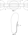
FIG. 8 illustrates different example arch and heel geometries; and -
FIG. 9 is a flow chart illustrating an example method. - Reference is made in the following detailed description to accompanying drawings, which form a part hereof, wherein like numerals may designate like parts throughout that are corresponding and/or analogous. It will be appreciated that the figures have not necessarily been drawn to scale, such as for simplicity and/or clarity of illustration.
- The invention is defined in the independent claim 1 and preferred embodiments are defined in the dependent claims 2-14.
- At times, footwear is manufactured using lasts, which are forms having a shape corresponding to that of a foot, and upon which components of the footwear are assembled. Lasts may have different shapes and dimensions based on the shapes and dimensions desired for footwear. For example, different lasts may be used for footwear for right and left feet, respectively; different lasts may be used for footwear for different foot sizes; different lasts may be used for footwear for feet of different width; different lasts may be used for footwear to have different arch geometry; etc. Because lasts are typically made using blocks of solid materials, such as woods, plastics, and metals, a large number of lasts may be used in footwear fabrication processes based on different footwear sizes and shapes. This can add to complexity of footwear fabrication (e.g., using a correctly-sized and shaped last) and last storage (e.g., having to store a number of lasts), among other things.
- A number of alternatives to solid lasts have been proposed. By way of example, lasts made of a selectively solidifiable material that may be selectively molded to a desired shape and size (hereinafter referred to alternatively as geometry) within a solid mold have been used. However, such an alternative would still use a number of solid molds for different foot geometries. Another alternative includes spreadable lasts in which portions of a last may be selectively moved to achieve different last geometries. For instance, a narrow last may be spread apart to act as a wide last, etc. Spreadable lasts may not be desirable for certain footwear manufacturing, however, such as cases in which materials are injected around the last, at least because the injected materials may enter gaps within the spreadable last.
- There may be a desire, therefore, for lasts that may be customizable without the complexity of having a number of different components and/or molds, and that may be usable for shoe manufacture processes that use injection molding, by way of example.
- In one case, a customizable last has a solid portion and an adjustable portion. The adjustable portion comprises a hollow receptacle to receive a moldable material that may be selectively solidified. An interchangeable mold cover is arranged to enclose the moldable material, and the moldable material may be caused to take a form corresponding to that of the interchangeable mold cover. The moldable material is to solidify for footwear manufacture, and to return to a moldable state (e.g., liquid, malleable, etc.) for adjustment of the adjustable portion. A component of the customizable last allows application of backpressure to the moldable material in order to enable forming the moldable material to the interchangeable mold cover. For instance, backpressure may be applied to the moldable material to cause the moldable material to press against the interchangeable mold cover. In one case, the adjustable portion may be arranged in a detachable lower portion of the customizable last to enable solidification of the moldable material separately from an upper portion of the customizable last. For example, an adjustable portion may correspond to an arch and/or heel of a last, and a moldable material may enable customization of an arch and/or heel portion of a last.
- It may be that use of a moldable material and an interchangeable mold cover may be desirable, such as to reduce complexity of last customization, such as by reducing a number of lasts and last attachments to be used in footwear manufacture. For instance, interchangeable mold covers may have a relatively small profile and may be stored in comparatively little space. Further, the moldable material may be used and reused for a number of different foot geometries. Additionally, the use of an adjustable portion may be desirable for footwear manufacture that uses injection molding, such as because injection molding may be performed without injected material entering gaps within a last.
- As noted above, there may be a desire for lasts that may be used to manufacture footwear that may be customized for a particular size and shape of a foot.
FIG. 1 shows a sample last 100 with anadjustable portion 120, indicated with a broken line to bring attention to a particular portion of last 100 that may be adjustable. Thus, for example, a particular size (width and height) ofadjustable portion 120 may be capable of changing. Furthermore, a particular shape ofadjustable portion 120 may be capable of being adjusted. To illustrate, a shape of an arch may vary among feet of different people and even among left and right feet of a particular person. Reference is made toFIG. 8 , which illustrates an outline of a sample foot and illustrating different arch and heel shapes and sizes, A-D (collectively, element 860). As should be appreciated, there may be a desire to provide a shoe with additional arch and heel support for feet having a shape corresponding to an arch and heel shape indicated by D. Conversely, less support may be needed for a foot having an arch and heel shape such as that indicated by A. Arch and heel shapes indicated by B and C indicate further additional examples and suggest a desire for an ability to customize lasts for particular feet shapes and sizes. Computer-enabled visioning technology may make it possible to scan feet, such as to achieve an accurate three dimensional model of a foot. In one example, computer-enabled visioning technology may be used in conjunction with pressure-sensing technology to detect foot pressure points. The three dimensional and pressure sensing models may be used in combination (or separately) to determine a particular shape and size for anadjustable portion 120 of last 100. - Returning to
FIG. 1 , last 100 comprises a solid (e.g. upper)portion 110, andadjustable portion 120 may be arranged in a lower portion of last, such as to enable customization of a portion (e.g., an arch, a heel, etc.) of footwear. Customization may be achieved in one case by using amoldable material 105, shown with crossed hash marks, arranged inadjustable portion 120. Aninterchangeable mold cover 125 facilitates molding ofmoldable material 105. - To illustrate,
moldable material 105 may be inserted in a hollow receptacle ofadjustable portion 120 of last 100. In one example,adjustable portion 120 may comprise an adjustable arch and/or heel portion, such as for providing last 100 with customized arch and/or heel geometries.Moldable material 105 may be malleable, flexible, and/or soft in order to be caused to take a desired form, such as a form determined based on computer-enabled visioning technology.Interchangeable mold cover 125 may have a size and shape that defines an inner surface that, when pressed against by a moldable material, yields a form corresponding to the form determined based on computer-enabled visioning scanning.Moldable material 105 may be caused to take a form corresponding to that of interchangeable mold cover 125 (which may correspond, in turn, to the desired form, as noted above), such as via the application of pressure tomoldable material 105.Moldable material 105 may be subsequently solidified. - Suitable materials for
moldable material 105 may comprise waxes with high melt temperatures, such as having melting points of approximately 60°C. Sample waxes can include carnuba, candelilla, and high-melt paraffin waxes. Alternatively, low melt temperature thermoplastics, such as having a melting point of approximately 60°C may be suitable to be used asmoldable material 105. An example low melt temperature thermoplastic includes CAPA 6800 polyester, by Perstorp Holding AB (and having a business address Neptunigatan 1, 211 20 Malmö, Sweden). Implementations with such materials asmoldable material 105 may use application of heat tomoldable material 105 to softenmoldable material 105 and to facilitate molding.Moldable material 105 may be cooled to yield a solidified form. - Other sample materials that may be suitable moldable materials may include supersaturated salt solutions, such as sodium acetate trihydrate. In one case, a supersaturated salt solution may be liquid prior to nucleation, which may be activated, such as by manipulating a piece of metal in the supersaturated salt solution (e.g., by bending the piece of metal or contacting it with a plunger, etc.). Nucleation of the supersaturated salt solution may cause
moldable material 105 to crystallize and solidify. Heating the solidifiedmoldable material 105 may make it possible to again moldmoldable material 105. - Other sample materials for
moldable material 105 may comprise materials responsive to electromagnetic fields (EMFs). By way of illustration, ferro-fluids and ferrous ball bearings may be used asmoldable material 105. Once a desired form is achieved with the ferro-fluid or ferrous bail bearings, a magnetic field may be applied to causemoldable material 105 to solidify for manufacture of footwear. - As should be apparent, therefore, use of
moldable material 105 in anadjustable portion 120 of last 100 and enclosed byinterchangeable mold cover 125 may enable last customization for footwear manufacture. - At times, it may be desirable to solidify a moldable material within a smaller space.
FIG. 2 illustrates an example last 200 that may comprise a detachablelower portion 215. For example, moldable material 205 may be received and solidified withinlower portion 215, such as to form a customized arch and/or heel shape and size.Lower portion 215 may be attached and detached fromupper portion 210 by engaging and disengaging, respectively, mountinghardware upper portion 210. - As such, in one example case,
lower portion 215 may be detached fromupper portion 210 by disengaging mountinghardware lower portion 215, such as behindinterchangeable mold cover 225 inFIG. 2 . Pressure is applied throughbackpressure cavity 230 and may cause moldable material 205 to take a shape corresponding to an interior surface of interchangeable mold cover 225 (which may thus correspond to an arch and heel shape in one example). For example, ifinterchangeable mold cover 225 corresponds to a desired arch and heel shape, using pressure to cause moldable material 205 to take a form corresponding tointerchangeable mold cover 225, last 200 may be customized to a particular arch and heel shape and size.Lower portion 215 may be attached toupper portion 210 resulting in a last, last 200, that may be usable for fabrication of footwear. For example, mountinghardware 235a may be used to mount last 200 on an apparatus for footwear manufacture. Components of footwear may be mounted on last 200 for assembly, for instance, and the resulting footwear may have a form reflecting the desired arch and heel shape and size solidified in moldable material 205 within adjustable portion 220. - As noted above, solidification and softening (e.g., rendering malleable or liquefying, for example) may occur in response to application of cold and heat, respectively, in one implementation. For example, a moldable material, such as moldable material 205 in
FIG. 2 , may be heated to near (or above) its melting point such that the moldable material may become malleable. While malleable (or in a liquid state), the moldable material may be pressed against aninterchangeable mold cover 225 to take a desired size and shape. The moldable material may be subsequently cooled to a solid state, such as by removal of a heating source and/or application of a cooling source, by way of non-limiting example. - Sources of heating and cooling may be arranged internally or externally to a moldable material. For example, in one case, heating and cooling conduits may be arranged within a last. In another example, it may be desirable to arrange sources of heating and cooling externally to a last, such as to reduce a mechanical complexity of the last, by way of illustration. For instance, as illustrated in
FIG. 3 , a heating and/orcooling source 350 may be arranged external to alower portion 315 of a last. The heating and/orcooling source 350 may be capable of enabling solidification and softening of a moldable material enclosed behindinterchangeable mold cover 325. While illustrated as an integrated element, heating and/orcooling source 350 may comprise independent heating and cooling elements, for example. - While many footwear manufacturing processes may involve exposing the last to temperatures lower than approximately 50°C, in some cases, a last may be exposed to temperatures above a melting point of a moldable material. To enable moldable material to remain solid while exposed to temperatures above a melting point of the material, an element demonstrating an ability to store thermal energy or having a good thermal mass (e.g., thermal capacitance) may be arranged within the last. Such thermal mass elements may thus allow a last containing a moldable material to be exposed to temperatures exceeding a melting point of the material. Thus, for instance, the presence of a thermal mass, such as
thermal mass 365 inFIG. 3 , may act to reduce temperature fluctuations and constrain a temperature of a moldable material to a band below the melting point of the moldable material, even when exposed to temperatures greater than that melting point. - Moving on to
FIG. 4 , a cross section of alower portion 415 is illustrated from the point of view illustrated by the arrows A inFIG. 3 . As discussed above, pressure is placed on amoldable material 405 viabackpressure cavity 430. Abackpressure cavity insert 440 may be used to distribute pressure acrossmoldable material 405 in a relatively uniform manner. Should backpressurecavity insert 440 be too soft, pressure applied throughbackpressure cavity 430 may cause localized depressions. In contrast, should backpressurecavity insert 440 be too hard, pressure applied throughbackpressure cavity 430 may not adequately translate tomoldable material 405, and thusmoldable material 405 may not take a desired shape and size. In one case, an examplebackpressure cavity insert 440 may comprise a silicon rubber with a durometer of approximately 30-40, by way of illustration. -
FIG. 4 uses anarrow 445 to illustrate a force being applied tobackpressure cavity insert 440. The force may be applied using spring force, by way of example. In another case, the force illustrated byarrow 445 may be applied using gas (e.g., air) pressure. Thus, in one case, air pressure may be directed towardsbackpressure cavity 430.Backpressure cavity insert 440 may distribute the pressure evenly throughout its surface. The pressure may thus be transmitted to amoldable material 405, which may be pressed against aninterchangeable mold cover 425, causingmoldable material 405 to take a shape and size corresponding to an interior surface ofmoldable material 405.Moldable material 405 be subsequently solidified. The resulting shape and size may be part of anadjustable portion 420 that corresponds to a desired foot geometry (e.g., an arch and heel shape and size). -
FIG. 5 is an exploded view of an examplelower portion 515. As illustrated,lower portion 515 may comprise multiple solid components that may be fixably connected to define anadjustable portion 520 comprising a hollow receptacle to receive a moldable material, such asmoldable material 405, discussed above. Aninterchangeable mold cover 525 may be attached and detached fromlower portion 515 to enclose the moldable material. Abackpressure cavity 530 may be arranged with respect to the hollow receptacle of theadjustable portion 520 for application of pressure on a moldable material. The back pressure may be applied tobackpressure cavity insert 540. Once the moldable material is solidified,lower portion 515 may be attached to an upper portion, such asupper portion 210 inFIG. 2 , via mountinghardware - By way of illustration, reference is made to
method 900 ofFIG. 9 in conjunction with the following brief discussion of elements inFIG. 5 . In one implementation, a moldable material, such as a high melt temperature wax, may be melted above its melting point to yield a softened material that may be molded to correspond to a desired shape and size. The moldable material may be inserted into a hollow receptacle ofadjustable portion 520 andinterchangeable mold cover 525 may be arranged onlower portion 515 to enclose the softened moldable material, such as shown byblock 905 ofFIG. 9 . Pressure may be applied to the moldable material throughbackpressure cavity 530 by a pressure mechanism, such as a spring or air pressure, by way of example, such as shown byblock 910 ofFIG. 9 . The applied pressure may cause the moldable material to take a form corresponding to that ofinterchangeable mold cover 525. The moldable material may be cooled to solidify (such as shown byblock 915 ofFIG. 9 ). And thelower portion 515 may be attached to an upper portion (e.g., 210, inFIG. 2 ) to yield a last with anadjustable portion 520 having a desired shape and size, and which may be used to manufacture footwear having a shape and size (e.g., of an arch height or heel width, by way of non-limiting example) that has been customized, such as based on computer vision scanning and/or pressure sensing systems. - As noted above, a number of moldable materials may be used in an adjustable portion of a last. As noted, in some example cases, high melt temperature waxes may be appropriate, such as for providing a desired form and able to withstand temperatures of footwear manufacture without melting. Additionally, low melt temperature thermoplastics may be suitable.
FIG. 6 illustrates samplemoldable materials moldable material 605a illustrates an implementation in which a metallic disk may be bent or struck, such as by a plunger mechanism, and nucleation may result, leading to crystallization of the supersaturated salt solution. In another implementation, such as shown bymoldable material 605b, one or more current pulses or electrical charges may be transmitted to the supersaturated solution to initiate nucleation. -
FIG. 7 illustrates yet another implementation in which instead of applying a current or manipulating a metal component, amoldable material 705 may be solidified by application of an electromagnetic field (EMF). A pair of magnets is illustrated to represent anEMF source 755. Of course, a number of suitable EMF sources would be suitable for causing amoldable material 705 to solidify in response to application of an EMF. For example, in one example case,moldable material 705 may comprise a ferro-fluid that may solidify in response to an EMF generated byEMF source 755. Thus, if the ferro-fluidmoldable material 705 is arranged within a hollow receptacle of an adjustable portion, an interchangeable mold cover is arranged to enclose themoldable material 705 within the last, backpressure is applied tomoldable material 705 through a backpressure cavity, and an EMF is applied to causemoldable material 705 to solidify, a resulting last may be used for footwear manufacture. - In view of the foregoing, a customizable shoe last may comprise a solid portion, an adjustable portion, and an interchangeable mold cover to enclose the adjustable portion. A moldable material that is selectively solidifiable for footwear manufacture may be arranged within the adjustable portion. The customizable shoe last may also comprise a backpressure cavity arranged with respect to the adjustable portion to enable application of pressure on the moldable portion through the backpressure cavity. The customizable shoe last may also comprise a thermal mass arranged within the last to constrain a temperature of the last below a melting point of the moldable material for shoe manufacture temperatures greater than the melting point.
- Suitable materials for the moldable material may comprise high melt temperature waxes, such as carnauba wax. Other suitable materials include low melt temperature thermoplastics, supersaturated salt solutions, and metals, metalloids, and alloys responsive to EMFs.
- In one example case, the customizable shoe last may comprise a detachable lower portion in which the adjustable portion may be arranged.
- In another example case, a shoe last comprises a solid upper portion, and a detachable lower portion. The detachable lower portion comprises a hollow receptacle to receive a moldable material that is solidifiable for footwear manufacture. The detachable lower portion also comprises a backpressure component for imparting pressure on moldable material arranged within the hollow receptacle. The detachable lower portion also comprises an interchangeable mold cover to enclose the moldable material inside the hollow receptacle.
- The backpressure component comprises a backpressure cavity arranged to be accessible from a top portion of the detachable lower portion. And the hollow receptacle is arranged on a bottom portion of the detachable lower portion. The hollow receptacle, the moldable material, and the interchangeable mold cover are arranged to enable customizable arch geometry. In one case, the moldable material is arranged within detachable lower portion such that heating and the cooling are to be applied externally to the shoe last. For example, the moldable material may comprise a melting point of approximately 60°C or more and may be applied externally.
- In yet another example, a customizable shoe last comprises a moldable material arranged within a receptacle of the customizable shoe last, an interchangeable mold cover arranged to enclose the receptacle and the moldable material, and a backpressure cavity arranged as to the moldable material to enable application of backpressure on the moldable material to mold the moldable material to correspond to a form of the interchangeable mold cover. The moldable material may solidify to retain the form of the interchangeable mold cover
- In the preceding description, various aspects of claimed subject matter have been described. For purposes of explanation, specifics, such as amounts, systems and/or configurations, as examples, were set forth. In other instances, well-known features were omitted and/or simplified so as not to obscure claimed subject matter. While certain features have been illustrated and/or described herein, many modifications, substitutions, changes and/or equivalents will now occur to those skilled in the art.
Claims (14)
- A customizable shoe last (100) comprising:a solid portion (110) and an adjustable portion (120), the adjustable portion to comprise a moldable material (105) that is selectively solidifiable for footwear manufacture;an interchangeable mold cover (125) to enclose the adjustable portion; characterised in thata backpressure cavity (230) arranged with respect to the adjustable portion to put pressure on moldable material of the adjustable portion.
- The customizable shoe last (100, 200) of claim 1, wherein the adjustable portion of the shoe last is arranged in a detachable lower portion of the shoe last.
- The customizable shoe last (100, 200) of claim 1, further comprising a thermal mass arranged to constrain a temperature of the moldable material below a melting point of the moldable material for shoe manufacture temperatures greater than the melting point of the moldable material.
- The customizable shoe last (100, 200) of claim 1, wherein the moldable material comprises a high melt temperature wax or a low melt temperature thermoplastic.
- The customizable shoe last (100, 200) of claim 1, wherein the moldable material comprises a supersaturated salt solution.
- The customizable shoe last (100, 200) of claim 5, wherein the supersaturated salt solution is solidifiable responsive to manipulation of a metal element within the supersaturated salt solution or application of an electrical charge to the supersaturated salt solution.
- The customizable shoe last (100, 200) of claim 1, wherein the moldable material comprises metals, metalloids, or alloys solidified responsive to application of a magnetic field.
- The customizable shoe last (100, 200) of claim 1, wherein the solid portion is a solid upper portion and the adjustable portioncomprises a detachable lower portion comprising a hollow receptacle to receive the moldable material; andwherein the interchangeable mold cover is to enclose the moldable material inside the hollow receptacle.
- The customizable shoe last (100, 200) of claim 8, wherein the backpressure cavity is arranged to be accessible from a top portion of the detachable lower portion and further wherein the hollow receptacle is arranged on a bottom portion of the detachable lower portion.
- The customizable shoe last (100, 200) of claim 1, wherein the hollow receptacle, the moldable material, and the interchangeable mold cover are arranged to enable customizable arch geometry, wherein arch geometry comprises shapes and sizes of arch and heel portions of the shoe last.
- The customizable shoe last (100, 200) of claim 8, wherein the moldable material is arranged within the detachable lower portion such that heating and the cooling are to be applied externally to the shoe last.
- The customizable shoe last (100, 200) of claim 1, wherein:
the moldable material comprises a melting point of approximately 60°C or more. - The customizable shoe last (100, 200) of claim 1, wherein the backpressure cavity is arranged to enable application of backpressure on the moldable material to mold the moldable material to correspond to a form of the interchangeable mold cover; wherein the moldable material solidifies to retain the form of the interchangeable mold cover.
- The customizable shoe last (100, 200) of claim 13, wherein the backpressure cavity comprises a backpressure cavity insert.
Applications Claiming Priority (1)
| Application Number | Priority Date | Filing Date | Title |
|---|---|---|---|
| PCT/US2017/037501 WO2018231223A1 (en) | 2017-06-14 | 2017-06-14 | Customizable lasts |
Publications (3)
| Publication Number | Publication Date |
|---|---|
| EP3638065A1 EP3638065A1 (en) | 2020-04-22 |
| EP3638065A4 EP3638065A4 (en) | 2021-03-03 |
| EP3638065B1 true EP3638065B1 (en) | 2023-08-02 |
Family
ID=64659922
Family Applications (1)
| Application Number | Title | Priority Date | Filing Date |
|---|---|---|---|
| EP17913700.5A Active EP3638065B1 (en) | 2017-06-14 | 2017-06-14 | Customizable lasts |
Country Status (4)
| Country | Link |
|---|---|
| US (1) | US11678724B2 (en) |
| EP (1) | EP3638065B1 (en) |
| CN (1) | CN110913718B (en) |
| WO (1) | WO2018231223A1 (en) |
Families Citing this family (2)
| Publication number | Priority date | Publication date | Assignee | Title |
|---|---|---|---|---|
| JP7506563B2 (en) * | 2020-09-04 | 2024-06-26 | 株式会社アシックス | DATA GENERATION DEVICE, SHOE LAST MAKING SYSTEM, AND DATA GENERATION METHOD |
| IT202300005307A1 (en) * | 2023-03-21 | 2024-09-21 | Lismec Srl | MOLD FOR THE PRODUCTION OF SKI BOOT SHELLS AND METHOD FOR THE PRODUCTION OF SKI BOOT SHELLS USING SAID MOLD |
Family Cites Families (26)
| Publication number | Priority date | Publication date | Assignee | Title |
|---|---|---|---|---|
| US1565057A (en) * | 1924-03-10 | 1925-12-08 | Chappell Frederick William | Last for boots, shoes, and the like |
| US1757594A (en) * | 1927-09-06 | 1930-05-06 | New England Wood Heel Co | Repaired last |
| GB650623A (en) * | 1947-03-14 | 1951-02-28 | Vilibald Pelant | A process for the production of lasts for boots and shoes |
| US3241166A (en) * | 1963-03-07 | 1966-03-22 | Genesco Inc | Shoe manufacture |
| US3335428A (en) * | 1964-11-02 | 1967-08-15 | Goodrich Co B F | Resilient prosthetic foot made from elastic polymers of different hardness |
| US3698105A (en) * | 1970-08-24 | 1972-10-17 | Batchelder Rubico Inc | Lasting element |
| FR2142311A5 (en) * | 1971-06-18 | 1973-01-26 | Mourier Andre | |
| US3724014A (en) * | 1971-11-19 | 1973-04-03 | Delro Eng Corp | Method for reshaping a shoe last |
| SU795530A1 (en) * | 1977-04-22 | 1981-01-15 | Минское Экспериментально-Конструктор-Ckoe Технологическое Бюро Кожгалан-Терейной И Фурнитурной Промышлен-Ности | Extensible shoe last |
| EP0159957A3 (en) * | 1984-04-22 | 1987-04-15 | Bar Aharon | Insole and method for producing same |
| US5881413A (en) * | 1995-02-28 | 1999-03-16 | James L. Throneburg | Shoe last and method of constructing a shoe |
| WO2004071229A2 (en) * | 2003-02-07 | 2004-08-26 | Ossur Hf | Method and kit for preparing a last for footwear |
| CN100366200C (en) * | 2005-05-09 | 2008-02-06 | 程一峰 | Shoe-tree sample last, and its making method |
| US7287293B2 (en) | 2005-08-12 | 2007-10-30 | Nike, Inc. | Custom fit system with adjustable last and method for custom fitting athletic shoes |
| RU55548U1 (en) * | 2006-04-21 | 2006-08-27 | Федеральное государственное унитарное предприятие "Владикавказский центр протезирования и ортопедии" (ФГУП "ВЦПО") Федерального агентства по здравоохранению и социальному развитию | ORTHOPEDIC PAD |
| US8968633B2 (en) * | 2006-05-03 | 2015-03-03 | Nike, Inc. | Method for manufacturing footwear last, and footwear last manufactured by the method |
| US8578534B2 (en) * | 2009-06-24 | 2013-11-12 | Nike, Inc. | Inflatable member |
| US20120304492A1 (en) * | 2011-06-03 | 2012-12-06 | The Chinese University Of Hong Kong | Last, method for manufacturing the last and footwear made from the last |
| CN202750844U (en) * | 2012-07-19 | 2013-02-27 | 成都市产品质量监督检验院 | Adjustable shoe tree |
| US9421726B2 (en) * | 2013-03-15 | 2016-08-23 | Chinook Asia Llc | Method of making injection molded footwear |
| US20160100650A1 (en) * | 2014-10-10 | 2016-04-14 | Easton Sports, Inc. | Skate boot including a thermoformable arch-support region |
| TWI556757B (en) * | 2015-01-16 | 2016-11-11 | 耐基創新公司 | Shape memory polymer footwear last system, method for forming footwear last from shape memory polymer footwear last pre-form, method for using single shape memory polymer footwear last pre-form in production of footwear of different shapes and sizes |
| CN204617235U (en) | 2015-05-18 | 2015-09-09 | 温州德士隆科技有限公司 | Heel setting machine gasbag-type rubber moulding mechanism |
| CN204763695U (en) * | 2015-07-29 | 2015-11-18 | 福建省宝树鞋楦有限公司 | Paste formula shoe tree |
| US20200297078A1 (en) * | 2016-09-09 | 2020-09-24 | Hewlett-Packard Development Company, L.P. | Shoe components based on customer data |
| DE112017005047T5 (en) * | 2016-11-09 | 2019-06-27 | Nike Innovate C.V. | Knitted textiles and uppers and method of making the same |
-
2017
- 2017-06-14 WO PCT/US2017/037501 patent/WO2018231223A1/en not_active Ceased
- 2017-06-14 CN CN201780093961.3A patent/CN110913718B/en not_active Expired - Fee Related
- 2017-06-14 US US16/077,697 patent/US11678724B2/en active Active
- 2017-06-14 EP EP17913700.5A patent/EP3638065B1/en active Active
Also Published As
| Publication number | Publication date |
|---|---|
| EP3638065A1 (en) | 2020-04-22 |
| EP3638065A4 (en) | 2021-03-03 |
| WO2018231223A1 (en) | 2018-12-20 |
| CN110913718A (en) | 2020-03-24 |
| CN110913718B (en) | 2022-02-15 |
| US11678724B2 (en) | 2023-06-20 |
| US20210177101A1 (en) | 2021-06-17 |
Similar Documents
| Publication | Publication Date | Title |
|---|---|---|
| US11678724B2 (en) | Customizable lasts | |
| JP2019166825A (en) | Reusable mold for injection molding and molding method | |
| JP2007523771A5 (en) | ||
| CN111212718B (en) | High speed injection molding for making optical articles using heating/cooling cycles | |
| CN104889348A (en) | Method for measuring high-temperature alloy critical nucleation super-cooling degree | |
| US20110017685A1 (en) | Fingernail color display device | |
| JP2020531318A (en) | Additional manufacturing with selective liquid cooling | |
| JP5442903B1 (en) | Molding apparatus, semi-solid metal production apparatus, molding method, and semi-solid metal production method | |
| EP3227080A1 (en) | Block mold | |
| JP2013502324A (en) | Method, apparatus, computer-readable storage medium and computer program for forming an object | |
| JPH11221842A (en) | Molding method of concave lens and mold for molding the same | |
| DK1346643T3 (en) | Method of making chocolate shells | |
| JP2010210818A (en) | Method for manufacturing optical component | |
| JP5965890B2 (en) | Molding apparatus, semi-solid metal production apparatus, molding method, and semi-solid metal production method | |
| JP2014237172A (en) | Manufacturing apparatus of solid-liquid coexistent state metal, manufacturing method of solid-liquid coexistent state metal, and molding method using solid-liquid coexistent state metal | |
| JP6143361B2 (en) | Injection mold | |
| TW200402357A (en) | Injection molding machine for lost wax casting and injection molding method for lost wax casting | |
| JP3127310B2 (en) | Manufacturing method of amorphous alloy | |
| JP2009241297A (en) | Method for manufacturing optical element, optical element molding mold, and optical element | |
| GB2472846A (en) | Solid freeform fabrication | |
| JP3038190B2 (en) | Mold, hollow molded product and molding method | |
| KR100541263B1 (en) | Chocolate Molding Mold Manufacturing Equipment and Chocolate Molding Mold Packaging Container | |
| JP3117153U (en) | Glass model | |
| JPS6440313A (en) | Method for molding high precision molded item | |
| JP2002264189A (en) | Molding system for plastic molded products |
Legal Events
| Date | Code | Title | Description |
|---|---|---|---|
| STAA | Information on the status of an ep patent application or granted ep patent |
Free format text: STATUS: THE INTERNATIONAL PUBLICATION HAS BEEN MADE |
|
| PUAI | Public reference made under article 153(3) epc to a published international application that has entered the european phase |
Free format text: ORIGINAL CODE: 0009012 |
|
| STAA | Information on the status of an ep patent application or granted ep patent |
Free format text: STATUS: REQUEST FOR EXAMINATION WAS MADE |
|
| 17P | Request for examination filed |
Effective date: 20191213 |
|
| AK | Designated contracting states |
Kind code of ref document: A1 Designated state(s): AL AT BE BG CH CY CZ DE DK EE ES FI FR GB GR HR HU IE IS IT LI LT LU LV MC MK MT NL NO PL PT RO RS SE SI SK SM TR |
|
| AX | Request for extension of the european patent |
Extension state: BA ME |
|
| DAV | Request for validation of the european patent (deleted) | ||
| DAX | Request for extension of the european patent (deleted) | ||
| A4 | Supplementary search report drawn up and despatched |
Effective date: 20210201 |
|
| RIC1 | Information provided on ipc code assigned before grant |
Ipc: A43D 3/02 20060101AFI20210126BHEP |
|
| GRAP | Despatch of communication of intention to grant a patent |
Free format text: ORIGINAL CODE: EPIDOSNIGR1 |
|
| STAA | Information on the status of an ep patent application or granted ep patent |
Free format text: STATUS: GRANT OF PATENT IS INTENDED |
|
| INTG | Intention to grant announced |
Effective date: 20230418 |
|
| GRAS | Grant fee paid |
Free format text: ORIGINAL CODE: EPIDOSNIGR3 |
|
| GRAA | (expected) grant |
Free format text: ORIGINAL CODE: 0009210 |
|
| STAA | Information on the status of an ep patent application or granted ep patent |
Free format text: STATUS: THE PATENT HAS BEEN GRANTED |
|
| AK | Designated contracting states |
Kind code of ref document: B1 Designated state(s): AL AT BE BG CH CY CZ DE DK EE ES FI FR GB GR HR HU IE IS IT LI LT LU LV MC MK MT NL NO PL PT RO RS SE SI SK SM TR |
|
| REG | Reference to a national code |
Ref country code: GB Ref legal event code: FG4D |
|
| REG | Reference to a national code |
Ref country code: CH Ref legal event code: EP |
|
| REG | Reference to a national code |
Ref country code: DE Ref legal event code: R096 Ref document number: 602017072335 Country of ref document: DE |
|
| REG | Reference to a national code |
Ref country code: IE Ref legal event code: FG4D |
|
| REG | Reference to a national code |
Ref country code: LT Ref legal event code: MG9D |
|
| REG | Reference to a national code |
Ref country code: NL Ref legal event code: MP Effective date: 20230802 |
|
| REG | Reference to a national code |
Ref country code: AT Ref legal event code: MK05 Ref document number: 1593611 Country of ref document: AT Kind code of ref document: T Effective date: 20230802 |
|
| PG25 | Lapsed in a contracting state [announced via postgrant information from national office to epo] |
Ref country code: GR Free format text: LAPSE BECAUSE OF FAILURE TO SUBMIT A TRANSLATION OF THE DESCRIPTION OR TO PAY THE FEE WITHIN THE PRESCRIBED TIME-LIMIT Effective date: 20231103 |
|
| PG25 | Lapsed in a contracting state [announced via postgrant information from national office to epo] |
Ref country code: IS Free format text: LAPSE BECAUSE OF FAILURE TO SUBMIT A TRANSLATION OF THE DESCRIPTION OR TO PAY THE FEE WITHIN THE PRESCRIBED TIME-LIMIT Effective date: 20231202 |
|
| PG25 | Lapsed in a contracting state [announced via postgrant information from national office to epo] |
Ref country code: SE Free format text: LAPSE BECAUSE OF FAILURE TO SUBMIT A TRANSLATION OF THE DESCRIPTION OR TO PAY THE FEE WITHIN THE PRESCRIBED TIME-LIMIT Effective date: 20230802 Ref country code: RS Free format text: LAPSE BECAUSE OF FAILURE TO SUBMIT A TRANSLATION OF THE DESCRIPTION OR TO PAY THE FEE WITHIN THE PRESCRIBED TIME-LIMIT Effective date: 20230802 Ref country code: PT Free format text: LAPSE BECAUSE OF FAILURE TO SUBMIT A TRANSLATION OF THE DESCRIPTION OR TO PAY THE FEE WITHIN THE PRESCRIBED TIME-LIMIT Effective date: 20231204 Ref country code: NO Free format text: LAPSE BECAUSE OF FAILURE TO SUBMIT A TRANSLATION OF THE DESCRIPTION OR TO PAY THE FEE WITHIN THE PRESCRIBED TIME-LIMIT Effective date: 20231102 Ref country code: NL Free format text: LAPSE BECAUSE OF FAILURE TO SUBMIT A TRANSLATION OF THE DESCRIPTION OR TO PAY THE FEE WITHIN THE PRESCRIBED TIME-LIMIT Effective date: 20230802 Ref country code: LV Free format text: LAPSE BECAUSE OF FAILURE TO SUBMIT A TRANSLATION OF THE DESCRIPTION OR TO PAY THE FEE WITHIN THE PRESCRIBED TIME-LIMIT Effective date: 20230802 Ref country code: LT Free format text: LAPSE BECAUSE OF FAILURE TO SUBMIT A TRANSLATION OF THE DESCRIPTION OR TO PAY THE FEE WITHIN THE PRESCRIBED TIME-LIMIT Effective date: 20230802 Ref country code: IS Free format text: LAPSE BECAUSE OF FAILURE TO SUBMIT A TRANSLATION OF THE DESCRIPTION OR TO PAY THE FEE WITHIN THE PRESCRIBED TIME-LIMIT Effective date: 20231202 Ref country code: HR Free format text: LAPSE BECAUSE OF FAILURE TO SUBMIT A TRANSLATION OF THE DESCRIPTION OR TO PAY THE FEE WITHIN THE PRESCRIBED TIME-LIMIT Effective date: 20230802 Ref country code: GR Free format text: LAPSE BECAUSE OF FAILURE TO SUBMIT A TRANSLATION OF THE DESCRIPTION OR TO PAY THE FEE WITHIN THE PRESCRIBED TIME-LIMIT Effective date: 20231103 Ref country code: FI Free format text: LAPSE BECAUSE OF FAILURE TO SUBMIT A TRANSLATION OF THE DESCRIPTION OR TO PAY THE FEE WITHIN THE PRESCRIBED TIME-LIMIT Effective date: 20230802 Ref country code: AT Free format text: LAPSE BECAUSE OF FAILURE TO SUBMIT A TRANSLATION OF THE DESCRIPTION OR TO PAY THE FEE WITHIN THE PRESCRIBED TIME-LIMIT Effective date: 20230802 |
|
| PG25 | Lapsed in a contracting state [announced via postgrant information from national office to epo] |
Ref country code: PL Free format text: LAPSE BECAUSE OF FAILURE TO SUBMIT A TRANSLATION OF THE DESCRIPTION OR TO PAY THE FEE WITHIN THE PRESCRIBED TIME-LIMIT Effective date: 20230802 |
|
| PG25 | Lapsed in a contracting state [announced via postgrant information from national office to epo] |
Ref country code: ES Free format text: LAPSE BECAUSE OF FAILURE TO SUBMIT A TRANSLATION OF THE DESCRIPTION OR TO PAY THE FEE WITHIN THE PRESCRIBED TIME-LIMIT Effective date: 20230802 |
|
| PG25 | Lapsed in a contracting state [announced via postgrant information from national office to epo] |
Ref country code: SM Free format text: LAPSE BECAUSE OF FAILURE TO SUBMIT A TRANSLATION OF THE DESCRIPTION OR TO PAY THE FEE WITHIN THE PRESCRIBED TIME-LIMIT Effective date: 20230802 Ref country code: RO Free format text: LAPSE BECAUSE OF FAILURE TO SUBMIT A TRANSLATION OF THE DESCRIPTION OR TO PAY THE FEE WITHIN THE PRESCRIBED TIME-LIMIT Effective date: 20230802 Ref country code: ES Free format text: LAPSE BECAUSE OF FAILURE TO SUBMIT A TRANSLATION OF THE DESCRIPTION OR TO PAY THE FEE WITHIN THE PRESCRIBED TIME-LIMIT Effective date: 20230802 Ref country code: EE Free format text: LAPSE BECAUSE OF FAILURE TO SUBMIT A TRANSLATION OF THE DESCRIPTION OR TO PAY THE FEE WITHIN THE PRESCRIBED TIME-LIMIT Effective date: 20230802 Ref country code: DK Free format text: LAPSE BECAUSE OF FAILURE TO SUBMIT A TRANSLATION OF THE DESCRIPTION OR TO PAY THE FEE WITHIN THE PRESCRIBED TIME-LIMIT Effective date: 20230802 Ref country code: CZ Free format text: LAPSE BECAUSE OF FAILURE TO SUBMIT A TRANSLATION OF THE DESCRIPTION OR TO PAY THE FEE WITHIN THE PRESCRIBED TIME-LIMIT Effective date: 20230802 Ref country code: SK Free format text: LAPSE BECAUSE OF FAILURE TO SUBMIT A TRANSLATION OF THE DESCRIPTION OR TO PAY THE FEE WITHIN THE PRESCRIBED TIME-LIMIT Effective date: 20230802 |
|
| REG | Reference to a national code |
Ref country code: DE Ref legal event code: R097 Ref document number: 602017072335 Country of ref document: DE |
|
| PG25 | Lapsed in a contracting state [announced via postgrant information from national office to epo] |
Ref country code: IT Free format text: LAPSE BECAUSE OF FAILURE TO SUBMIT A TRANSLATION OF THE DESCRIPTION OR TO PAY THE FEE WITHIN THE PRESCRIBED TIME-LIMIT Effective date: 20230802 |
|
| PLBE | No opposition filed within time limit |
Free format text: ORIGINAL CODE: 0009261 |
|
| STAA | Information on the status of an ep patent application or granted ep patent |
Free format text: STATUS: NO OPPOSITION FILED WITHIN TIME LIMIT |
|
| 26N | No opposition filed |
Effective date: 20240503 |
|
| PG25 | Lapsed in a contracting state [announced via postgrant information from national office to epo] |
Ref country code: SI Free format text: LAPSE BECAUSE OF FAILURE TO SUBMIT A TRANSLATION OF THE DESCRIPTION OR TO PAY THE FEE WITHIN THE PRESCRIBED TIME-LIMIT Effective date: 20230802 |
|
| PG25 | Lapsed in a contracting state [announced via postgrant information from national office to epo] |
Ref country code: BG Free format text: LAPSE BECAUSE OF FAILURE TO SUBMIT A TRANSLATION OF THE DESCRIPTION OR TO PAY THE FEE WITHIN THE PRESCRIBED TIME-LIMIT Effective date: 20230802 |
|
| PG25 | Lapsed in a contracting state [announced via postgrant information from national office to epo] |
Ref country code: BG Free format text: LAPSE BECAUSE OF FAILURE TO SUBMIT A TRANSLATION OF THE DESCRIPTION OR TO PAY THE FEE WITHIN THE PRESCRIBED TIME-LIMIT Effective date: 20230802 |
|
| REG | Reference to a national code |
Ref country code: DE Ref legal event code: R119 Ref document number: 602017072335 Country of ref document: DE |
|
| PG25 | Lapsed in a contracting state [announced via postgrant information from national office to epo] |
Ref country code: MC Free format text: LAPSE BECAUSE OF FAILURE TO SUBMIT A TRANSLATION OF THE DESCRIPTION OR TO PAY THE FEE WITHIN THE PRESCRIBED TIME-LIMIT Effective date: 20230802 |
|
| REG | Reference to a national code |
Ref country code: CH Ref legal event code: PL |
|
| PG25 | Lapsed in a contracting state [announced via postgrant information from national office to epo] |
Ref country code: LU Free format text: LAPSE BECAUSE OF NON-PAYMENT OF DUE FEES Effective date: 20240614 |
|
| GBPC | Gb: european patent ceased through non-payment of renewal fee |
Effective date: 20240614 |
|
| PG25 | Lapsed in a contracting state [announced via postgrant information from national office to epo] |
Ref country code: DE Free format text: LAPSE BECAUSE OF NON-PAYMENT OF DUE FEES Effective date: 20250101 |
|
| PG25 | Lapsed in a contracting state [announced via postgrant information from national office to epo] |
Ref country code: IE Free format text: LAPSE BECAUSE OF NON-PAYMENT OF DUE FEES Effective date: 20240614 |
|
| PG25 | Lapsed in a contracting state [announced via postgrant information from national office to epo] |
Ref country code: BE Free format text: LAPSE BECAUSE OF NON-PAYMENT OF DUE FEES Effective date: 20240630 Ref country code: CH Free format text: LAPSE BECAUSE OF NON-PAYMENT OF DUE FEES Effective date: 20240630 |
|
| PG25 | Lapsed in a contracting state [announced via postgrant information from national office to epo] |
Ref country code: FR Free format text: LAPSE BECAUSE OF NON-PAYMENT OF DUE FEES Effective date: 20240630 |
|
| PG25 | Lapsed in a contracting state [announced via postgrant information from national office to epo] |
Ref country code: GB Free format text: LAPSE BECAUSE OF NON-PAYMENT OF DUE FEES Effective date: 20240614 |
|
| REG | Reference to a national code |
Ref country code: BE Ref legal event code: MM Effective date: 20240630 |
|
| PG25 | Lapsed in a contracting state [announced via postgrant information from national office to epo] |
Ref country code: CY Free format text: LAPSE BECAUSE OF FAILURE TO SUBMIT A TRANSLATION OF THE DESCRIPTION OR TO PAY THE FEE WITHIN THE PRESCRIBED TIME-LIMIT; INVALID AB INITIO Effective date: 20170614 |
|
| PG25 | Lapsed in a contracting state [announced via postgrant information from national office to epo] |
Ref country code: HU Free format text: LAPSE BECAUSE OF FAILURE TO SUBMIT A TRANSLATION OF THE DESCRIPTION OR TO PAY THE FEE WITHIN THE PRESCRIBED TIME-LIMIT; INVALID AB INITIO Effective date: 20170614 |