EP3637791B1 - Enceinte acoustique comportant une coque en matière plastique - Google Patents
Enceinte acoustique comportant une coque en matière plastique Download PDFInfo
- Publication number
- EP3637791B1 EP3637791B1 EP19201591.5A EP19201591A EP3637791B1 EP 3637791 B1 EP3637791 B1 EP 3637791B1 EP 19201591 A EP19201591 A EP 19201591A EP 3637791 B1 EP3637791 B1 EP 3637791B1
- Authority
- EP
- European Patent Office
- Prior art keywords
- shell
- insert
- transverse axis
- speaker cabinet
- edge
- Prior art date
- Legal status (The legal status is an assumption and is not a legal conclusion. Google has not performed a legal analysis and makes no representation as to the accuracy of the status listed.)
- Active
Links
Images




Classifications
-
- H—ELECTRICITY
- H04—ELECTRIC COMMUNICATION TECHNIQUE
- H04R—LOUDSPEAKERS, MICROPHONES, GRAMOPHONE PICK-UPS OR LIKE ACOUSTIC ELECTROMECHANICAL TRANSDUCERS; ELECTRIC HEARING AIDS; PUBLIC ADDRESS SYSTEMS
- H04R1/00—Details of transducers, loudspeakers or microphones
- H04R1/20—Arrangements for obtaining desired frequency or directional characteristics
- H04R1/22—Arrangements for obtaining desired frequency or directional characteristics for obtaining desired frequency characteristic only
- H04R1/28—Transducer mountings or enclosures modified by provision of mechanical or acoustic impedances, e.g. resonator, damping means
- H04R1/2869—Reduction of undesired resonances, i.e. standing waves within enclosure, or of undesired vibrations, i.e. of the enclosure itself
- H04R1/2884—Reduction of undesired resonances, i.e. standing waves within enclosure, or of undesired vibrations, i.e. of the enclosure itself by means of the enclosure structure, i.e. strengthening or shape of the enclosure
- H04R1/2888—Reduction of undesired resonances, i.e. standing waves within enclosure, or of undesired vibrations, i.e. of the enclosure itself by means of the enclosure structure, i.e. strengthening or shape of the enclosure for loudspeaker transducers
-
- H—ELECTRICITY
- H04—ELECTRIC COMMUNICATION TECHNIQUE
- H04R—LOUDSPEAKERS, MICROPHONES, GRAMOPHONE PICK-UPS OR LIKE ACOUSTIC ELECTROMECHANICAL TRANSDUCERS; ELECTRIC HEARING AIDS; PUBLIC ADDRESS SYSTEMS
- H04R1/00—Details of transducers, loudspeakers or microphones
- H04R1/02—Casings; Cabinets ; Supports therefor; Mountings therein
-
- H—ELECTRICITY
- H04—ELECTRIC COMMUNICATION TECHNIQUE
- H04R—LOUDSPEAKERS, MICROPHONES, GRAMOPHONE PICK-UPS OR LIKE ACOUSTIC ELECTROMECHANICAL TRANSDUCERS; ELECTRIC HEARING AIDS; PUBLIC ADDRESS SYSTEMS
- H04R1/00—Details of transducers, loudspeakers or microphones
- H04R1/02—Casings; Cabinets ; Supports therefor; Mountings therein
- H04R1/025—Arrangements for fixing loudspeaker transducers, e.g. in a box, furniture
-
- H—ELECTRICITY
- H04—ELECTRIC COMMUNICATION TECHNIQUE
- H04R—LOUDSPEAKERS, MICROPHONES, GRAMOPHONE PICK-UPS OR LIKE ACOUSTIC ELECTROMECHANICAL TRANSDUCERS; ELECTRIC HEARING AIDS; PUBLIC ADDRESS SYSTEMS
- H04R1/00—Details of transducers, loudspeakers or microphones
- H04R1/20—Arrangements for obtaining desired frequency or directional characteristics
- H04R1/22—Arrangements for obtaining desired frequency or directional characteristics for obtaining desired frequency characteristic only
- H04R1/28—Transducer mountings or enclosures modified by provision of mechanical or acoustic impedances, e.g. resonator, damping means
- H04R1/2869—Reduction of undesired resonances, i.e. standing waves within enclosure, or of undesired vibrations, i.e. of the enclosure itself
- H04R1/2892—Mountings or supports for transducers
- H04R1/2896—Mountings or supports for transducers for loudspeaker transducers
-
- H—ELECTRICITY
- H04—ELECTRIC COMMUNICATION TECHNIQUE
- H04R—LOUDSPEAKERS, MICROPHONES, GRAMOPHONE PICK-UPS OR LIKE ACOUSTIC ELECTROMECHANICAL TRANSDUCERS; ELECTRIC HEARING AIDS; PUBLIC ADDRESS SYSTEMS
- H04R2201/00—Details of transducers, loudspeakers or microphones covered by H04R1/00 but not provided for in any of its subgroups
- H04R2201/02—Details casings, cabinets or mounting therein for transducers covered by H04R1/02 but not provided for in any of its subgroups
- H04R2201/029—Manufacturing aspects of enclosures transducers
Definitions
- Such a shell is technically and aesthetically satisfactory.
- a large loudspeaker for example a woofer
- certain design choices of the acoustic enclosure are likely to cause mechanical instability. or hull vibrations, for example caused by pressure fluctuations inside the acoustic enclosure.
- a known solution to this problem consists in fixing the loudspeaker on the internal side of a shell portion, on the periphery of the opening.
- this fixing of the loudspeaker proves to be difficult, even impossible for certain shapes of hulls.
- the document FR 2 593 011 A1 describes a method for manufacturing a hollow structure of the multilayer type incorporating a sheet of lead.
- CN 106 911 975 A describes a sheet metal for a loudspeaker housing shell.
- US 5,731,554 A describes an optimum transducer mounting system for loudspeakers which optimizes the attachment of a transducer to a loudspeaker enclosure.
- An object of the invention is therefore to provide an acoustic enclosure as described above and which solves or reduces the problems of mechanical instability or vibration of the shell mentioned above.
- the subject of the invention is a loudspeaker according to claim 1.
- the acoustic enclosure comprises one or more of the characteristics corresponding to claims 2 to 8, taken individually or in all technically possible combinations.
- the loudspeaker 1 is for example an active loudspeaker, that is to say it comprises an audio signal player and an amplifier (not shown, just as other electrical or electronic elements of the loudspeaker are not shown). loudspeaker not relevant to explain the invention).
- the acoustic enclosure 1 rests on a surface S, preferably horizontal.
- the acoustic enclosure has for example a generally oblong shape along a longitudinal axis L, which advantageously forms an angle with the surface S, as visible on the picture 3 .
- the acoustic enclosure thus has a front part 3 and a rear part 5 along the longitudinal axis L, the front part being higher than the rear part with respect to the surface S, as visible on the picture 3 .
- the acoustic enclosure 1 is not oblong, but is for example spherical, or has any other external shape.
- the acoustic enclosure comprises a plastic shell 7 defining two openings 9A, 9B, and two loudspeakers 11A, 11B extending respectively across the two openings.
- a transverse axis T is also defined, which in the example is perpendicular to the longitudinal axis L, and along which the two loudspeakers 11A, 11B are placed head to tail.
- the transverse axis T is for example parallel to the surface S, and is therefore horizontal in the example.
- the acoustic enclosure advantageously comprises a metal frame 13, on which the shell 7 is for example nested, advantageously along the longitudinal axis L.
- the two loudspeakers 11A and 11B are for example bass loudspeakers.
- basic loudspeaker is meant a loudspeaker suitable for broadcasting sound waves of frequencies lower than 1000 Hz, preferentially lower than 500 Hz, even more preferentially lower than 150 Hz.
- the acoustic enclosure advantageously comprises a third loudspeaker (not shown) for example fixed in a housing 15 formed by the shell 7 in the front part 3.
- the shell 7 defines only one of the openings 9A, 9B and the acoustic enclosure comprises only one of the loudspeakers 11A, 11B.
- the longitudinal axis L and the transverse axis T are not perpendicular to each other.
- the acoustic enclosure comprises two metal inserts 17A, 17B overmolded by the shell 7. ( Figure 4 ).
- the acoustic enclosure has for example a generally symmetrical appearance along a plane P perpendicular to the transverse axis T.
- the third loudspeaker (not shown) located in the housing 15 is for example centered on the longitudinal axis L.
- it is suitable for broadcasting sound waves of frequencies ranging from 300 Hz to 20 kHz, or even from 150 Hz to 40kHz.
- the frame 13 is advantageously a casting, for example aluminum.
- the frame 13 comprises an outer part 17 defining with the shell 7 an internal volume 19 of the acoustic enclosure.
- the reinforcement 13 advantageously comprises an internal part 21 integral with the external part 17 and extending along the plane P.
- the outer part 17 comprises a rear portion 23 forming the rear part 5 of the acoustic enclosure, and a sole 25 projecting under the loudspeakers 11A, 11B along the longitudinal axis L from the rear portion 23.
- the outer part 17 advantageously has a general "U" shape.
- the outer part 17 and the shell 7 for example are adapted to fit one inside the other, here along the longitudinal axis L.
- the internal part 21 advantageously forms a support on which the two loudspeakers 11A, 11B are rigidly fixed by screwing, gluing, or any other means allowing the loudspeakers to resist a transverse tearing force greater than 100 N (newton ), preferably greater than 1000 N.
- the shell 9 is advantageously in one piece.
- one-piece is meant that the hull is in one piece and does not comprise parts fixed to one another by mechanical means.
- the shell is advantageously fixed to the internal part 21 of the frame using a single nut 27 located in the housing 15.
- the shell 7 comprises, successively along the longitudinal axis L, a front part 29 forming a portion of a sphere, an intermediate part 31 forming a portion of a cylinder, two rear walls 33A, 33B respectively located longitudinally between the openings 9A, 9B and the rear portion 23 of the frame, and a skirt 35 located under the loudspeakers 11A, 11B.
- the hull has for example a general "U" shape in view along an axis of view E, perpendicular to the longitudinal axis L and to the transverse axis T.
- the branches of the "U” are formed by the rear walls 33A, 33B which project longitudinally beyond the intermediate portion 31 towards the rear part 5 of the acoustic enclosure.
- the shell comprises an inner layer 37 ( figure 4 ) delimiting the internal volume 19, and an outer layer 39, or appearance layer, visible from the outside of the acoustic enclosure.
- the inner layer is advantageously thicker than the outer layer.
- the inner layer comprises for example polycarbonate (PC) reinforced with 15% to 25% by mass of glass fibers.
- the outer layer is for example made of acrylonitrile butadiene styrene (ABS).
- the openings 9A, 9B are delimited respectively by edges 41A, 41B of the shell.
- the openings 9A, 9B are for example circular in view along the transverse axis T.
- the rear walls 33A, 33B extend for example perpendicular to the transverse axis T.
- the rear walls are delimited longitudinally, on the one hand, by the edges 41A, 41B and, on the other hand, by edges 43A, 43B .
- edges 43A, 43B are for example semi-circular in view along the transverse axis T.
- the edges 43A, 43B respectively define rails 45A, 45B adapted to cooperate with the rear portion 17 of the frame to immobilize the rear walls 33A , 33B transversely.
- edges 45A, 45B define grooves, and not rails, for the same purpose.
- Two flexible seals 47A, 47B provide sealing between the loudspeakers 11A, 11B and the shell.
- edges 41A, 41B of the shell are not rigidly linked to the loudspeakers 11A, 11B other than by the frame 13.
- the edges 41A, 41B are cantilevered with respect to the two loudspeakers 11A, 11B .
- the two inserts 17A, 17B are advantageously structurally identical to each other. In the example, they are arranged symmetrically on either side of the plane P. Also only the insert 17A will be described below with reference to the figures 4 to 7 .
- the insert 17A is advantageously made of stainless steel, for example AISI 430L.
- the thickness of the metal sheet at the origin of the insert is for example between 0.6 mm and 1.5 mm.
- Stamping does not create very pronounced reliefs or hollows. Their extension along the transverse axis T does not exceed, for example, one twentieth of the greatest extension E0 of the insert.
- the insert 17A is in one piece.
- the insert 17A comprises a circular part 49 advantageously located in the edge 41A of the shell, and another part 51 adjacent to the circular part and advantageously located in the rear wall 33A of the shell.
- the circular part 49 has a radially outer edge 53 with respect to the transverse axis T advantageously defining notches 55.
- the circular part has a radially inner edge 57 defining protrusions 59 along the transverse axis T.
- the notches 55 are advantageously regularly spaced angularly around the transverse axis T, for example over approximately 225°.
- the circular part comprises for example between ten and twenty cutouts 55.
- the cutouts 55 are twelve in number in the example.
- the notches 55 are adapted to block the edge 41A of the shell in rotation with respect to the circular part 49 around the transverse axis T.
- the indentations 55 are adapted to block the relative movements between the plastic material of the shell and the metal insert, in particular linked to differential expansions.
- the radially inner edge 57 is advantageously raised transversely on the side towards which the protuberances 59 point, advantageously towards the internal volume 19. This dropped edge makes it possible to increase the rigidity of the circular part 49 of the insert.
- the other part 51 is advantageously integral with the circular part 49.
- the other part 51 is separated from the circular part 49.
- the insert 17A is made up of three or more separate parts.
- the other part 51 forms pleats 61 which are advantageously parallel to each other.
- the other part 51 comprises a plurality of perforations 63, at least some of which are distributed along a peripheral strip 65 of the other part.
- the other part comprises portions 67 raised transversely.
- the folds 61 are perpendicular to the longitudinal axis L, and advantageously perpendicular to the transverse axis T.
- the folds 61 are adapted to stiffen the other part 51, and therefore the rear wall 33A in bending around the longitudinal axis L .
- the folds 61 are undulations of the insert.
- the portions 67 are for example raised relative to the peripheral strip 65 in the transverse direction.
- the raised portions advantageously rise to the same level as the protrusions 59 transversely.
- the raised portions 67 also contribute to the rigidity of the other part 51.
- a rotary mold (not shown) is used in which the two inserts 17A, 17B are placed in the final position that they must occupy in the shell relative to each other. Thanks to its shape, in particular the protrusions 59 and the raised portions 67, each of the inserts occupies a given position (not shown) relative to the mold.
- the protrusions 59 and raised portions 67 also serve as thermal contact points for each of the inserts to assume a uniform temperature equal to that of the mold.
- the plastic material of the inner layer 37 is injected into the mold and overmolds each of the inserts.
- the notches 55, the perforations 63, and the folds 61 ensure good adhesion of the plastic material to the metal.
- the plastic material of the outer layer 39 is then injected into the mold and coats the inner layer 37 on the outer side of the future acoustic enclosure.
- the edges 41A, 41B are stabilized mechanically, both at rest and from the vibration point of view.
- the amplitude of the vibrations is attenuated.
- Posterior wall vibration (or “pumping”) is reduced or eliminated.
- the problems of mechanical instability or vibration of the hull are therefore reduced.
Landscapes
- Health & Medical Sciences (AREA)
- Otolaryngology (AREA)
- Physics & Mathematics (AREA)
- Engineering & Computer Science (AREA)
- Acoustics & Sound (AREA)
- Signal Processing (AREA)
- Details Of Audible-Bandwidth Transducers (AREA)
- Diaphragms For Electromechanical Transducers (AREA)
Description
- La présente invention concerne une enceinte acoustique comportant :
- une coque en matière plastique définissant au moins une ouverture, et
- au moins un haut-parleur définissant un axe transversal de l'enceinte acoustique et s'étendant en travers de l'ouverture.
- Une telle coque donne satisfaction techniquement et esthétiquement. Toutefois, la présence d'un haut-parleur volumineux, par exemple un haut-parleur de grave, en travers de l'ouverture définie par la coque, et certains choix de conception de l'enceinte acoustique sont susceptibles d'entraîner une instabilité mécanique ou des vibrations de la coque, par exemple causées par des fluctuations de pression à l'intérieur de l'enceinte acoustique.
- Une solution connue à ce problème consiste à fixer le haut-parleur du côté interne d'une portion de coque, sur le pourtour de l'ouverture. Toutefois, cette fixation du haut-parleur s'avère difficile, voire impossible pour certaines formes de coques.
- Selon son abrégé, le document
FR 2 593 011 A1 - Selon son abrégé,
CN 106 911 975 A décrit une tôle pour une coque de boîtier de haut-parleur. - Selon son abrégé,
US 5 731 554 A décrit un système de montage de transducteur optimal pour haut-parleurs qui optimise la fixation d'un transducteur à une enceinte de haut-parleur. - L'article de Michael Brown "Devialet Phantom review: Forget everything you thought you knew about speaker technology", du 13 novembre 2015, XP055589418, décrit le haut-parleur « Phantom » commercialisé par le demandeur. Un but de l'invention est donc de fournir une enceinte acoustique telle que décrite ci-dessus et qui résolve ou réduise les problèmes d'instabilité mécanique ou de vibration de la coque mentionnés ci-dessus.
- A cet effet, l'invention a pour objet une enceinte acoustique selon la revendication 1.
- Selon des modes de réalisation particuliers, l'enceinte acoustique comprend l'une ou plusieurs des caractéristiques correspondant aux revendications 2 à 8, prise(s) isolément ou selon toutes les combinaisons techniquement possibles.
- L'invention sera mieux comprise à la lecture de la description qui va suivre, donnée uniquement à titre d'exemple, et faite en se référant aux dessins annexés, sur lesquels :
- la
figure 1 est une vue en perspective d'une enceinte acoustique selon l'invention, - la
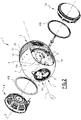
figure 2 est une vue en perspective de l'enceinte acoustique représentée sur lafigure 1 , éclatée selon un axe transversal défini par des haut-parleurs, - la
figure 3 est une vue de côté de la coque de l'enceinte acoustique représentée sur lesfigures 1 et2 , - la
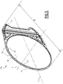
figure 4 est une vue en coupe de la coque représentée sur lesfigures 1 à 3 , selon un plan passant par l'axe transversal et par un axe longitudinal de l'enceinte acoustique, - la
figure 5 est une vue en perspective d'un insert métallique présent dans la coque représentée sur lesfigures 1 à 4 , - la
figure 6 est une vue de face de l'insert représenté sur lafigure 5 , et - la
figure 7 est une vue de côté, par la tranche, de l'insert représenté sur lesfigures 5 et6 . - En référence aux
figures 1 à 3 , on décrit une enceinte acoustique 1 selon l'invention. - L'enceinte acoustique 1 est par exemple une enceinte active, c'est-à-dire qu'elle comprend un lecteur de signaux audio et un amplificateur (non représentés, tout comme ne sont pas représentés d'autres éléments électriques ou électroniques de l'enceinte acoustique non pertinents pour expliquer l'invention).
- Dans l'exemple représenté, l'enceinte acoustique 1 repose sur une surface S, de préférence horizontale. L'enceinte acoustique présente par exemple une forme générale oblongue selon un axe longitudinal L, qui forme avantageusement un angle avec la surface S, comme visible sur la
figure 3 . L'enceinte acoustique présente ainsi une partie avant 3 et une partie arrière 5 selon l'axe longitudinal L, la partie avant étant plus haute que la partie arrière par rapport à la surface S, comme visible sur lafigure 3 . - Selon une variante non représentée, l'enceinte acoustique 1 n'est pas oblongue, mais est par exemple sphérique, ou présente toute autre forme extérieure.
- L'enceinte acoustique comprend une coque 7 en matière plastique définissant deux ouvertures 9A, 9B, et deux haut-parleurs 11A, 11B s'étendant respectivement en travers des deux ouvertures.
- On définit également un axe transversal T, qui est dans l'exemple perpendiculaire à l'axe longitudinal L, et selon lequel les deux haut-parleurs 11A, 11B sont placés têtebêche. L'axe transversal T est par exemple parallèle à la surface S, et est donc horizontal dans l'exemple.
- L'enceinte acoustique comprend avantageusement une armature métallique 13, sur laquelle la coque 7 est par exemple emboîtée, avantageusement selon l'axe longitudinal L.
- Les deux-parleurs 11A et 11B sont par exemple des haut-parleurs de grave.
- Par « haut-parleur de grave », on entend un haut-parleur adapté pour diffuser des ondes sonores de fréquences inférieures à 1000 Hz, préférentiellement inférieures à 500 Hz, encore plus préférentiellement inférieures à 150 Hz.
- L'enceinte acoustique comprend avantageusement un troisième haut-parleur (non représenté) par exemple fixé dans un logement 15 formé par la coque 7 dans la partie avant 3.
- Selon une variante non représentée, la coque 7 ne définit qu'une seule des ouvertures 9A, 9B et l'enceinte acoustique ne comprend qu'un seul des haut-parleurs 11A, 11B.
- Selon une autre variante non représentée, l'axe longitudinal L et l'axe transversal T ne sont pas perpendiculaires l'un à l'autre.
- L'enceinte acoustique comprend deux inserts 17A, 17B métalliques surmoulés par la coque 7. (
Figure 4 ). - L'enceinte acoustique présente par exemple un aspect général symétrique selon un plan P perpendiculaire à l'axe transversal T.
- Le troisième haut-parleur (non représenté) situé dans le logement 15 est par exemple centré sur l'axe longitudinal L. Avantageusement, il est adapté pour diffuser des ondes sonores de fréquences allant de 300 Hz à 20 kHz, voire de 150 Hz à 40 kHz.
- L'armature 13 est avantageusement une pièce de fonderie, par exemple en aluminium. L'armature 13 comprend une partie externe 17 définissant avec la coque 7 un volume interne 19 de l'enceinte acoustique. L'armature 13 comprend avantageusement une partie interne 21 solidaire de la partie externe 17 et s'étendant selon le plan P.
- La partie externe 17 comporte une portion arrière 23 formant la partie arrière 5 de l'enceinte acoustique, et une semelle 25 s'avançant sous les haut-parleurs 11A, 11B selon l'axe longitudinal L à partir de la portion arrière 23.
- En vue selon l'axe transversal T, la partie externe 17 présente avantageusement une forme générale en « U ». La partie externe 17 et la coque 7 par exemple sont adaptées pour s'emboîter l'une dans l'autre, ici selon l'axe longitudinal L.
- La partie interne 21 forme avantageusement un support sur lequel les deux haut-parleurs 11A, 11B sont rigidement fixés par vissage, collage, ou tout autre moyen permettant aux haut-parleurs de résister à une force transversale d'arrachement supérieure à 100 N (newton), de préférence supérieure à 1000 N.
- La coque 9 est avantageusement monobloc. On entend par « monobloc » que la coque est d'un seul tenant et ne comporte pas de pièces fixées les unes sur les autres par des moyens mécaniques. La coque est avantageusement fixée sur la partie interne 21 de l'armature à l'aide d'un unique écrou 27 situé dans le logement 15.
- Comme visible sur la
figure 3 , la coque 7 comprend, successivement selon l'axe longitudinal L, une partie avant 29 formant une portion de sphère, une partie intermédiaire 31 formant une portion de cylindre, deux parois postérieures 33A, 33B respectivement situées longitudinalement entre les ouvertures 9A, 9B et la portion arrière 23 de l'armature, et une jupe 35 située sous les haut-parleurs 11A, 11B. - La coque présente par exemple une forme générale en « U » en vue selon un axe de vue E, perpendiculaire à l'axe longitudinal L et à l'axe transversal T. Les branches du « U » sont formées par les parois postérieures 33A, 33B qui s'avancent longitudinalement au-delà de la portion intermédiaire 31 vers la partie arrière 5 de l'enceinte acoustique.
- La coque comprend une couche interne 37 (
figure 4 ) délimitant le volume interne 19, et une couche externe 39, ou couche d'aspect, visible depuis l'extérieur de l'enceinte acoustique. La couche interne est avantageusement plus épaisse que la couche externe. La couche interne comporte par exemple du polycarbonate (PC) renforcée par 15% à 25% en masse de fibres de verre. - La couche externe est par exemple constituée d'acrylonitrile butadiène styrène (ABS).
- Les ouvertures 9A, 9B sont délimitées respectivement par des bords 41A, 41B de la coque. Les ouvertures 9A, 9B sont par exemple circulaires en vue selon l'axe transversal T.
- Les parois postérieures 33A, 33B s'étendent par exemple perpendiculairement à l'axe transversal T. Les parois postérieures sont délimitées longitudinalement, d'une part, par les bords 41A, 41B et, d'autre part, par des bords 43A, 43B.
- Les bords 43A, 43B sont par exemple hémi-circulaires en vue selon l'axe transversal T. Les bords 43A, 43B définissent respectivement des rails 45A, 45B adaptés pour coopérer avec la portion arrière 17 de l'armature pour immobiliser les parois postérieures 33A, 33B transversalement.
- Selon une variante non représentée, les bords 45A, 45B définissent des rainures, et non des rails, dans le même but.
- Deux joints souples 47A, 47B assurent l'étanchéité entre les haut-parleurs 11A, 11B et la coque.
- Les bords 41A, 41B de la coque ne sont pas rigidement liés aux haut-parleurs 11A, 11B autrement que par l'armature 13. Les bords 41A, 41B sont en porte-à-faux par rapport aux deux haut-parleurs 11A, 11B.
- Les deux inserts 17A, 17B sont avantageusement structurellement identiques l'un à l'autre. Dans l'exemple, ils sont disposés symétriquement de part et d'autre du plan P. Aussi seul l'insert 17A sera décrit ci-après en référence aux
figures 4 à 7 . - L'insert 17A est avantageusement en acier inoxydable, par exemple en AISI 430L.
- L'insert 17A présente, dans l'exemple représenté, une forme générale plane, par exemple perpendiculaire à l'axe transversal T. Cet aspect général plan résulte par exemple d'un procédé de fabrication de l'insert comportant les étapes suivantes :
- obtention d'une feuille métallique,
- découpe de la feuille,
- optionnellement perforation de la feuille, et
- emboutissage de la feuille découpée et optionnellement perforée.
- L'épaisseur de la feuille métallique à l'origine de l'insert est par exemple comprise entre 0,6 mm et 1,5mm.
- L'emboutissage ne crée pas de reliefs ou de creux très prononcés. Leur extension selon l'axe transversal T n'excède pas, par exemple, un vingtième de la plus grande extension E0 de l'insert.
- Dans l'exemple représenté, l'insert 17A est d'un seul tenant.
- L'insert 17A comprend une partie circulaire 49 avantageusement située dans le bord 41A de la coque, et une autre partie 51 adjacente à la partie circulaire et avantageusement située dans la paroi postérieure 33A de la coque.
- La partie circulaire 49 comporte un bord radialement extérieur 53 par rapport à l'axe transversal T définissant avantageusement des échancrures 55. La partie circulaire comporte un bord radialement intérieur 57 définissant des protubérances 59 selon l'axe transversal T.
- Les échancrures 55 sont avantageusement régulièrement espacées angulairement autour de l'axe transversal T, par exemple sur environ 225°. La partie circulaire comprend par exemple entre dix et vingt échancrures 55. Les échancrures 55 sont au nombre de douze dans l'exemple.
- Les échancrures 55 sont adaptées pour bloquer le bord 41A de la coque en rotation par rapport à la partie circulaire 49 autour de l'axe transversal T.
- Les échancrures 55 sont adaptées pour bloquer les mouvements relatifs entre la matière plastique de la coque et l'insert métallique, notamment liés aux dilatations différentielles.
- Le bord radialement intérieur 57 est avantageusement relevé transversalement du côté vers lequel les protubérances 59 pointent, avantageusement vers le volume interne 19. Ce bord tombé permet d'augmenter la rigidité de la partie circulaire 49 de l'insert.
- L'autre partie 51 est avantageusement venue de matière avec la partie circulaire 49.
- Selon une variante non représentée, l'autre partie 51 est disjointe de la partie circulaire 49.
- Selon d'autres variantes encore (non représentées), l'insert 17A est composé de trois pièces distinctes, ou plus.
- L'autre partie 51 forme des plis 61 avantageusement parallèles entre eux. L'autre partie 51 comporte une pluralité de perforations 63, dont au moins certaines sont réparties le long d'une bande périphérique 65 de l'autre partie. L'autre partie comprend des portions 67 surélevées transversalement.
- Les plis 61 sont perpendiculaires à l'axe longitudinal L, et avantageusement perpendiculaires à l'axe transversal T. Les plis 61 sont adaptés pour rigidifier l'autre partie 51, et donc la paroi postérieure 33A en flexion autour de l'axe longitudinal L.
- En variante, les plis 61 sont des ondulations de l'insert.
- Les portions 67 sont par exemple surélevées par rapport à la bande périphérique 65 dans le sens transversal. Les portions surélevées s'élèvent avantageusement au même niveau que les protubérances 59 transversalement.
- Les portions surélevées 67 contribuent également à la rigidité de l'autre partie 51.
- Pour fabriquer la coque 7, un moule rotatif (non représenté) est utilisé dans lequel on place les deux inserts 17A, 17B dans la position finale qu'ils doivent occuper dans la coque l'un par rapport à l'autre. Grâce à sa forme, en particulier les protubérances 59 et les portions surélevées 67, chacun des inserts occupe une position (non représentée) donnée par rapport au moule.
- Les protubérances 59 et les portions surélevées 67 servent également de points de contact thermique pour que chacun des inserts prenne une température uniforme égale à celle du moule.
- Puis la matière plastique de la couche interne 37 est injectée dans le moule et vient surmouler chacun des inserts. Les échancrures 55, les perforations 63, et les plis 61 assurent une bonne adhésion de la matière plastique sur le métal.
- Ensuite la forme du moule est modifiée. La matière plastique de la couche externe 39 est alors injectée dans le moule et vient napper la couche interne 37 du côté extérieur de la future enceinte acoustique.
- Grâce aux caractéristiques décrites ci-dessus, les bords 41A, 41B sont stabilisés mécaniquement, tant au repos que du point de vue vibratoire. L'amplitude des vibrations est atténuée. La vibration des parois postérieures (ou « pompage ») est réduite ou supprimée. Les problèmes d'instabilité mécanique ou de vibration de la coque sont donc réduits.
Claims (8)
- Enceinte acoustique (1) comportant :- une coque (7) en matière plastique définissant au moins une ouverture (9A), et- au moins un haut-parleur (11A) définissant un axe transversal (T) de l'enceinte acoustique (1) et s'étendant en travers de l'ouverture (9A), et- au moins un insert (17A) métallique surmoulé par la coque (7), l'insert (17A) comprenant une partie circulaire (49) située dans un bord (41A) de la coque (7) délimitant l'ouverture (9A),la partie circulaire (49) comportant un bord radialement intérieur (57) par rapport à l'axe transversal (T), caractérisé en ce que le bord radialement intérieur (57) définit des protubérances (59) selon l'axe transversal (T).
- Enceinte acoustique (1) selon la revendication 1, dans laquelle la coque (7) comprend :- une couche interne (37) comportant du polycarbonate (PC) et entre 15% et 25% en masse de fibres de verres, et- une couche externe (39) comportant de l'acrylonitrile butadiène styrène (ABS),l'insert (17A) étant surmoulé par la couche interne (37).
- Enceinte acoustique (1) selon la revendication 1 ou 2, dans laquelle l'insert (17A) est en acier inoxydable, de préférence l'AISI 430L.
- Enceinte acoustique (1) selon l'une quelconque des revendications 1 à 3, dans laquelle la partie circulaire (49) comporte un bord radialement extérieur (53) par rapport à l'axe transversal (T), le bord radialement extérieur (53) définissant des échancrures (55) adaptées pour bloquer le bord (41A) de la coque (7) en rotation par rapport à la partie circulaire (49) de l'insert (17A) autour de l'axe transversal (T).
- Enceinte acoustique (1) selon l'une quelconque des revendications 1 à 4, dans laquelle l'insert (17A) comprend une autre partie (51) adjacente à la partie circulaire (49), et de préférence venue de matière avec la partie circulaire (49).
- Enceinte acoustique (1) selon la revendication 5, dans laquelle l'autre partie (51) comporte forme des plis (61) ou des ondulations parallèles entre eux.
- Enceinte acoustique (1) selon la revendication 5 ou 6, dans laquelle l'autre partie (51) comporte une pluralité de perforations (63), au moins certaines des perforations (63) étant réparties sur une bande périphérique (65) de l'autre partie (51).
- Enceinte acoustique (1) selon l'une quelconque des revendications 5 à 7, dans laquelle l'autre partie (51) comprend des portions (67) surélevées selon l'axe transversal (T).
Applications Claiming Priority (1)
| Application Number | Priority Date | Filing Date | Title |
|---|---|---|---|
| FR1859313A FR3087069B1 (fr) | 2018-10-08 | 2018-10-08 | Enceinte acoustique comportant une coque en matiere plastique |
Publications (2)
| Publication Number | Publication Date |
|---|---|
| EP3637791A1 EP3637791A1 (fr) | 2020-04-15 |
| EP3637791B1 true EP3637791B1 (fr) | 2022-04-06 |
Family
ID=65244184
Family Applications (1)
| Application Number | Title | Priority Date | Filing Date |
|---|---|---|---|
| EP19201591.5A Active EP3637791B1 (fr) | 2018-10-08 | 2019-10-07 | Enceinte acoustique comportant une coque en matière plastique |
Country Status (2)
| Country | Link |
|---|---|
| EP (1) | EP3637791B1 (fr) |
| FR (1) | FR3087069B1 (fr) |
Family Cites Families (3)
| Publication number | Priority date | Publication date | Assignee | Title |
|---|---|---|---|---|
| FR2593011A1 (fr) * | 1986-01-14 | 1987-07-17 | Guillou Marc | Procede de fabrication d'une structure creuse, incorporant une feuille de plomb, et enceinte acoustique realisee selon ce procede |
| US5731554A (en) * | 1996-10-30 | 1998-03-24 | Sony Corporation | Optimized loudspeaker transducer monuting system |
| CN106911975B (zh) * | 2015-12-23 | 2023-11-10 | 奥音科技(镇江)有限公司 | 用于扬声器箱壳体的金属片以及扬声器箱壳体 |
-
2018
- 2018-10-08 FR FR1859313A patent/FR3087069B1/fr active Active
-
2019
- 2019-10-07 EP EP19201591.5A patent/EP3637791B1/fr active Active
Also Published As
| Publication number | Publication date |
|---|---|
| EP3637791A1 (fr) | 2020-04-15 |
| FR3087069A1 (fr) | 2020-04-10 |
| FR3087069B1 (fr) | 2022-02-25 |
Similar Documents
| Publication | Publication Date | Title |
|---|---|---|
| EP3993996B1 (fr) | Revêtement insonorisant comportant une structure alvéolaire | |
| EP3637790B1 (fr) | Enceinte acoustique à deux haut-parleurs dos à dos fixés sur une armature interne | |
| EP3395675B1 (fr) | Panneau pour le traitement acoustique comprenant une structure acoustiquement resistive poreuse comportant des canaux de connexion | |
| EP3635229B1 (fr) | Panneau acoustique et ensemble propulsif associé | |
| EP3395676B1 (fr) | Panneau pour le traitement acoustique comprenant des alveoles contenant chacune une pluralite de conduits | |
| WO2025257645A1 (fr) | Enceinte acoustique et procédé de mise à niveau d'une enceinte acoustique | |
| WO2007034098A1 (fr) | Tranche de pain de mie, pain de mie, procede de fabrication de ce pain de mie et moule employe dans ce procede | |
| EP3637791A1 (fr) | Enceinte acoustique comportant une coque en matière plastique | |
| EP3637787B1 (fr) | Enceinte acoustique comportant une coque en matière plastique monobloc | |
| EP4279261A1 (fr) | Panneau acoustique pour aéronef à large bande de fréquence d'atténuation de bruit combinant deux résonateurs et procédé de fabrication du panneau acoustique | |
| WO2009083567A1 (fr) | Virole interieure de stator pour la delimitation d'un flux primaire de turbomoteur d'aeronef | |
| EP2172388A1 (fr) | Pare-boue de véhicule permettant l'absorption de vibrations acoustiques | |
| FR2878221A1 (fr) | Planche de bord a amortissement acoustique pour vehicule automobile | |
| EP0712758B1 (fr) | Réceptacle étanche pour haut-parleur dans un véhicule | |
| EP3734990B1 (fr) | Pavillon acoustique, enceinte acoustique comportant un tel pavillon acoustique et procede de fabrication d'un tel pavillon acoustique | |
| EP3892010B1 (fr) | Piece de rigidification pour caisson d'enceinte acoustique | |
| EP4125085B1 (fr) | Haut-parleur comprenant une membrane montée réversiblement, et enceinte acoustique intégrant un tel haut-parleur | |
| EP4672225A1 (fr) | Dispositif d'isolation acoustique pour un aeronef | |
| WO2010086536A1 (fr) | Conduit d'echappement insonorise pour turbomoteur | |
| FR2738450A1 (fr) | Tondeuse a gazon du type a au moins une lame tournant sous un capot, avec un capot de constitution particuliere | |
| EP1705779B1 (fr) | Unité motrice comprenant un moteur électrique intégré dans un support formant cavité d'atténuation du rayonnement acoustique. | |
| WO2025242613A1 (fr) | Vitrage isolant décoratif à acoustique amélioré | |
| EP3090903B1 (fr) | Paroi de véhicule automobile comportant deux peaux munies d'excroissances et prenant en sandwich une âme | |
| FR3055695A1 (fr) | Assemblage pour le support avec filtrage de vibrations d'un element fonctionnel sur un element structurel du corps d'un engin et element fonctionnel y relatif | |
| FR2619595A1 (fr) | Roue motrice multi-pales pour turbine a flux traversant |
Legal Events
| Date | Code | Title | Description |
|---|---|---|---|
| PUAI | Public reference made under article 153(3) epc to a published international application that has entered the european phase |
Free format text: ORIGINAL CODE: 0009012 |
|
| STAA | Information on the status of an ep patent application or granted ep patent |
Free format text: STATUS: THE APPLICATION HAS BEEN PUBLISHED |
|
| AK | Designated contracting states |
Kind code of ref document: A1 Designated state(s): AL AT BE BG CH CY CZ DE DK EE ES FI FR GB GR HR HU IE IS IT LI LT LU LV MC MK MT NL NO PL PT RO RS SE SI SK SM TR |
|
| AX | Request for extension of the european patent |
Extension state: BA ME |
|
| STAA | Information on the status of an ep patent application or granted ep patent |
Free format text: STATUS: REQUEST FOR EXAMINATION WAS MADE |
|
| 17P | Request for examination filed |
Effective date: 20200917 |
|
| RBV | Designated contracting states (corrected) |
Designated state(s): AL AT BE BG CH CY CZ DE DK EE ES FI FR GB GR HR HU IE IS IT LI LT LU LV MC MK MT NL NO PL PT RO RS SE SI SK SM TR |
|
| GRAP | Despatch of communication of intention to grant a patent |
Free format text: ORIGINAL CODE: EPIDOSNIGR1 |
|
| STAA | Information on the status of an ep patent application or granted ep patent |
Free format text: STATUS: GRANT OF PATENT IS INTENDED |
|
| RIC1 | Information provided on ipc code assigned before grant |
Ipc: H04R 1/02 20060101ALN20211006BHEP Ipc: H04R 1/28 20060101AFI20211006BHEP |
|
| INTG | Intention to grant announced |
Effective date: 20211026 |
|
| GRAS | Grant fee paid |
Free format text: ORIGINAL CODE: EPIDOSNIGR3 |
|
| GRAA | (expected) grant |
Free format text: ORIGINAL CODE: 0009210 |
|
| STAA | Information on the status of an ep patent application or granted ep patent |
Free format text: STATUS: THE PATENT HAS BEEN GRANTED |
|
| AK | Designated contracting states |
Kind code of ref document: B1 Designated state(s): AL AT BE BG CH CY CZ DE DK EE ES FI FR GB GR HR HU IE IS IT LI LT LU LV MC MK MT NL NO PL PT RO RS SE SI SK SM TR |
|
| REG | Reference to a national code |
Ref country code: GB Ref legal event code: FG4D Free format text: NOT ENGLISH |
|
| REG | Reference to a national code |
Ref country code: CH Ref legal event code: EP |
|
| REG | Reference to a national code |
Ref country code: AT Ref legal event code: REF Ref document number: 1482507 Country of ref document: AT Kind code of ref document: T Effective date: 20220415 |
|
| REG | Reference to a national code |
Ref country code: DE Ref legal event code: R096 Ref document number: 602019013345 Country of ref document: DE |
|
| REG | Reference to a national code |
Ref country code: IE Ref legal event code: FG4D Free format text: LANGUAGE OF EP DOCUMENT: FRENCH |
|
| REG | Reference to a national code |
Ref country code: LT Ref legal event code: MG9D |
|
| REG | Reference to a national code |
Ref country code: NL Ref legal event code: MP Effective date: 20220406 |
|
| REG | Reference to a national code |
Ref country code: AT Ref legal event code: MK05 Ref document number: 1482507 Country of ref document: AT Kind code of ref document: T Effective date: 20220406 |
|
| PG25 | Lapsed in a contracting state [announced via postgrant information from national office to epo] |
Ref country code: NL Free format text: LAPSE BECAUSE OF FAILURE TO SUBMIT A TRANSLATION OF THE DESCRIPTION OR TO PAY THE FEE WITHIN THE PRESCRIBED TIME-LIMIT Effective date: 20220406 |
|
| PG25 | Lapsed in a contracting state [announced via postgrant information from national office to epo] |
Ref country code: SE Free format text: LAPSE BECAUSE OF FAILURE TO SUBMIT A TRANSLATION OF THE DESCRIPTION OR TO PAY THE FEE WITHIN THE PRESCRIBED TIME-LIMIT Effective date: 20220406 Ref country code: PT Free format text: LAPSE BECAUSE OF FAILURE TO SUBMIT A TRANSLATION OF THE DESCRIPTION OR TO PAY THE FEE WITHIN THE PRESCRIBED TIME-LIMIT Effective date: 20220808 Ref country code: NO Free format text: LAPSE BECAUSE OF FAILURE TO SUBMIT A TRANSLATION OF THE DESCRIPTION OR TO PAY THE FEE WITHIN THE PRESCRIBED TIME-LIMIT Effective date: 20220706 Ref country code: LT Free format text: LAPSE BECAUSE OF FAILURE TO SUBMIT A TRANSLATION OF THE DESCRIPTION OR TO PAY THE FEE WITHIN THE PRESCRIBED TIME-LIMIT Effective date: 20220406 Ref country code: HR Free format text: LAPSE BECAUSE OF FAILURE TO SUBMIT A TRANSLATION OF THE DESCRIPTION OR TO PAY THE FEE WITHIN THE PRESCRIBED TIME-LIMIT Effective date: 20220406 Ref country code: GR Free format text: LAPSE BECAUSE OF FAILURE TO SUBMIT A TRANSLATION OF THE DESCRIPTION OR TO PAY THE FEE WITHIN THE PRESCRIBED TIME-LIMIT Effective date: 20220707 Ref country code: FI Free format text: LAPSE BECAUSE OF FAILURE TO SUBMIT A TRANSLATION OF THE DESCRIPTION OR TO PAY THE FEE WITHIN THE PRESCRIBED TIME-LIMIT Effective date: 20220406 Ref country code: ES Free format text: LAPSE BECAUSE OF FAILURE TO SUBMIT A TRANSLATION OF THE DESCRIPTION OR TO PAY THE FEE WITHIN THE PRESCRIBED TIME-LIMIT Effective date: 20220406 Ref country code: BG Free format text: LAPSE BECAUSE OF FAILURE TO SUBMIT A TRANSLATION OF THE DESCRIPTION OR TO PAY THE FEE WITHIN THE PRESCRIBED TIME-LIMIT Effective date: 20220706 Ref country code: AT Free format text: LAPSE BECAUSE OF FAILURE TO SUBMIT A TRANSLATION OF THE DESCRIPTION OR TO PAY THE FEE WITHIN THE PRESCRIBED TIME-LIMIT Effective date: 20220406 |
|
| PG25 | Lapsed in a contracting state [announced via postgrant information from national office to epo] |
Ref country code: RS Free format text: LAPSE BECAUSE OF FAILURE TO SUBMIT A TRANSLATION OF THE DESCRIPTION OR TO PAY THE FEE WITHIN THE PRESCRIBED TIME-LIMIT Effective date: 20220406 Ref country code: PL Free format text: LAPSE BECAUSE OF FAILURE TO SUBMIT A TRANSLATION OF THE DESCRIPTION OR TO PAY THE FEE WITHIN THE PRESCRIBED TIME-LIMIT Effective date: 20220406 Ref country code: LV Free format text: LAPSE BECAUSE OF FAILURE TO SUBMIT A TRANSLATION OF THE DESCRIPTION OR TO PAY THE FEE WITHIN THE PRESCRIBED TIME-LIMIT Effective date: 20220406 Ref country code: IS Free format text: LAPSE BECAUSE OF FAILURE TO SUBMIT A TRANSLATION OF THE DESCRIPTION OR TO PAY THE FEE WITHIN THE PRESCRIBED TIME-LIMIT Effective date: 20220806 |
|
| REG | Reference to a national code |
Ref country code: DE Ref legal event code: R097 Ref document number: 602019013345 Country of ref document: DE |
|
| PG25 | Lapsed in a contracting state [announced via postgrant information from national office to epo] |
Ref country code: SM Free format text: LAPSE BECAUSE OF FAILURE TO SUBMIT A TRANSLATION OF THE DESCRIPTION OR TO PAY THE FEE WITHIN THE PRESCRIBED TIME-LIMIT Effective date: 20220406 Ref country code: SK Free format text: LAPSE BECAUSE OF FAILURE TO SUBMIT A TRANSLATION OF THE DESCRIPTION OR TO PAY THE FEE WITHIN THE PRESCRIBED TIME-LIMIT Effective date: 20220406 Ref country code: RO Free format text: LAPSE BECAUSE OF FAILURE TO SUBMIT A TRANSLATION OF THE DESCRIPTION OR TO PAY THE FEE WITHIN THE PRESCRIBED TIME-LIMIT Effective date: 20220406 Ref country code: EE Free format text: LAPSE BECAUSE OF FAILURE TO SUBMIT A TRANSLATION OF THE DESCRIPTION OR TO PAY THE FEE WITHIN THE PRESCRIBED TIME-LIMIT Effective date: 20220406 Ref country code: DK Free format text: LAPSE BECAUSE OF FAILURE TO SUBMIT A TRANSLATION OF THE DESCRIPTION OR TO PAY THE FEE WITHIN THE PRESCRIBED TIME-LIMIT Effective date: 20220406 Ref country code: CZ Free format text: LAPSE BECAUSE OF FAILURE TO SUBMIT A TRANSLATION OF THE DESCRIPTION OR TO PAY THE FEE WITHIN THE PRESCRIBED TIME-LIMIT Effective date: 20220406 |
|
| PLBE | No opposition filed within time limit |
Free format text: ORIGINAL CODE: 0009261 |
|
| STAA | Information on the status of an ep patent application or granted ep patent |
Free format text: STATUS: NO OPPOSITION FILED WITHIN TIME LIMIT |
|
| 26N | No opposition filed |
Effective date: 20230110 |
|
| PG25 | Lapsed in a contracting state [announced via postgrant information from national office to epo] |
Ref country code: AL Free format text: LAPSE BECAUSE OF FAILURE TO SUBMIT A TRANSLATION OF THE DESCRIPTION OR TO PAY THE FEE WITHIN THE PRESCRIBED TIME-LIMIT Effective date: 20220406 |
|
| REG | Reference to a national code |
Ref country code: DE Ref legal event code: R119 Ref document number: 602019013345 Country of ref document: DE |
|
| PG25 | Lapsed in a contracting state [announced via postgrant information from national office to epo] |
Ref country code: SI Free format text: LAPSE BECAUSE OF FAILURE TO SUBMIT A TRANSLATION OF THE DESCRIPTION OR TO PAY THE FEE WITHIN THE PRESCRIBED TIME-LIMIT Effective date: 20220406 Ref country code: MC Free format text: LAPSE BECAUSE OF FAILURE TO SUBMIT A TRANSLATION OF THE DESCRIPTION OR TO PAY THE FEE WITHIN THE PRESCRIBED TIME-LIMIT Effective date: 20220406 |
|
| REG | Reference to a national code |
Ref country code: CH Ref legal event code: PL |
|
| P01 | Opt-out of the competence of the unified patent court (upc) registered |
Effective date: 20230425 |
|
| REG | Reference to a national code |
Ref country code: BE Ref legal event code: MM Effective date: 20221031 |
|
| PG25 | Lapsed in a contracting state [announced via postgrant information from national office to epo] |
Ref country code: LU Free format text: LAPSE BECAUSE OF NON-PAYMENT OF DUE FEES Effective date: 20221007 |
|
| PG25 | Lapsed in a contracting state [announced via postgrant information from national office to epo] |
Ref country code: LI Free format text: LAPSE BECAUSE OF NON-PAYMENT OF DUE FEES Effective date: 20221031 Ref country code: DE Free format text: LAPSE BECAUSE OF NON-PAYMENT OF DUE FEES Effective date: 20230503 Ref country code: CH Free format text: LAPSE BECAUSE OF NON-PAYMENT OF DUE FEES Effective date: 20221031 |
|
| PG25 | Lapsed in a contracting state [announced via postgrant information from national office to epo] |
Ref country code: BE Free format text: LAPSE BECAUSE OF NON-PAYMENT OF DUE FEES Effective date: 20221031 |
|
| PG25 | Lapsed in a contracting state [announced via postgrant information from national office to epo] |
Ref country code: IE Free format text: LAPSE BECAUSE OF NON-PAYMENT OF DUE FEES Effective date: 20221007 |
|
| PG25 | Lapsed in a contracting state [announced via postgrant information from national office to epo] |
Ref country code: IT Free format text: LAPSE BECAUSE OF FAILURE TO SUBMIT A TRANSLATION OF THE DESCRIPTION OR TO PAY THE FEE WITHIN THE PRESCRIBED TIME-LIMIT Effective date: 20220406 |
|
| PG25 | Lapsed in a contracting state [announced via postgrant information from national office to epo] |
Ref country code: HU Free format text: LAPSE BECAUSE OF FAILURE TO SUBMIT A TRANSLATION OF THE DESCRIPTION OR TO PAY THE FEE WITHIN THE PRESCRIBED TIME-LIMIT; INVALID AB INITIO Effective date: 20191007 |
|
| PG25 | Lapsed in a contracting state [announced via postgrant information from national office to epo] |
Ref country code: CY Free format text: LAPSE BECAUSE OF FAILURE TO SUBMIT A TRANSLATION OF THE DESCRIPTION OR TO PAY THE FEE WITHIN THE PRESCRIBED TIME-LIMIT Effective date: 20220406 |
|
| PG25 | Lapsed in a contracting state [announced via postgrant information from national office to epo] |
Ref country code: MK Free format text: LAPSE BECAUSE OF FAILURE TO SUBMIT A TRANSLATION OF THE DESCRIPTION OR TO PAY THE FEE WITHIN THE PRESCRIBED TIME-LIMIT Effective date: 20220406 |
|
| GBPC | Gb: european patent ceased through non-payment of renewal fee |
Effective date: 20231007 |
|
| PG25 | Lapsed in a contracting state [announced via postgrant information from national office to epo] |
Ref country code: GB Free format text: LAPSE BECAUSE OF NON-PAYMENT OF DUE FEES Effective date: 20231007 |
|
| PG25 | Lapsed in a contracting state [announced via postgrant information from national office to epo] |
Ref country code: GB Free format text: LAPSE BECAUSE OF NON-PAYMENT OF DUE FEES Effective date: 20231007 |
|
| PG25 | Lapsed in a contracting state [announced via postgrant information from national office to epo] |
Ref country code: MT Free format text: LAPSE BECAUSE OF FAILURE TO SUBMIT A TRANSLATION OF THE DESCRIPTION OR TO PAY THE FEE WITHIN THE PRESCRIBED TIME-LIMIT Effective date: 20220406 |
|
| PG25 | Lapsed in a contracting state [announced via postgrant information from national office to epo] |
Ref country code: BG Free format text: LAPSE BECAUSE OF FAILURE TO SUBMIT A TRANSLATION OF THE DESCRIPTION OR TO PAY THE FEE WITHIN THE PRESCRIBED TIME-LIMIT Effective date: 20220406 |
|
| PG25 | Lapsed in a contracting state [announced via postgrant information from national office to epo] |
Ref country code: BG Free format text: LAPSE BECAUSE OF FAILURE TO SUBMIT A TRANSLATION OF THE DESCRIPTION OR TO PAY THE FEE WITHIN THE PRESCRIBED TIME-LIMIT Effective date: 20220406 |
|
| PGFP | Annual fee paid to national office [announced via postgrant information from national office to epo] |
Ref country code: FR Payment date: 20250909 Year of fee payment: 7 |
|
| PG25 | Lapsed in a contracting state [announced via postgrant information from national office to epo] |
Ref country code: TR Free format text: LAPSE BECAUSE OF FAILURE TO SUBMIT A TRANSLATION OF THE DESCRIPTION OR TO PAY THE FEE WITHIN THE PRESCRIBED TIME-LIMIT Effective date: 20220406 |