EP3637638A1 - Portable wireless avionics intra-communication adapter location system - Google Patents
Portable wireless avionics intra-communication adapter location system Download PDFInfo
- Publication number
- EP3637638A1 EP3637638A1 EP19201559.2A EP19201559A EP3637638A1 EP 3637638 A1 EP3637638 A1 EP 3637638A1 EP 19201559 A EP19201559 A EP 19201559A EP 3637638 A1 EP3637638 A1 EP 3637638A1
- Authority
- EP
- European Patent Office
- Prior art keywords
- waic
- pattern
- adapter
- light
- location
- Prior art date
- Legal status (The legal status is an assumption and is not a legal conclusion. Google has not performed a legal analysis and makes no representation as to the accuracy of the status listed.)
- Granted
Links
Images




Classifications
-
- H—ELECTRICITY
- H04—ELECTRIC COMMUNICATION TECHNIQUE
- H04W—WIRELESS COMMUNICATION NETWORKS
- H04W4/00—Services specially adapted for wireless communication networks; Facilities therefor
- H04W4/30—Services specially adapted for particular environments, situations or purposes
- H04W4/40—Services specially adapted for particular environments, situations or purposes for vehicles, e.g. vehicle-to-pedestrians [V2P]
- H04W4/48—Services specially adapted for particular environments, situations or purposes for vehicles, e.g. vehicle-to-pedestrians [V2P] for in-vehicle communication
-
- H—ELECTRICITY
- H04—ELECTRIC COMMUNICATION TECHNIQUE
- H04B—TRANSMISSION
- H04B7/00—Radio transmission systems, i.e. using radiation field
- H04B7/14—Relay systems
- H04B7/15—Active relay systems
- H04B7/185—Space-based or airborne stations; Stations for satellite systems
- H04B7/18502—Airborne stations
- H04B7/18506—Communications with or from aircraft, i.e. aeronautical mobile service
-
- H—ELECTRICITY
- H04—ELECTRIC COMMUNICATION TECHNIQUE
- H04B—TRANSMISSION
- H04B10/00—Transmission systems employing electromagnetic waves other than radio-waves, e.g. infrared, visible or ultraviolet light, or employing corpuscular radiation, e.g. quantum communication
- H04B10/11—Arrangements specific to free-space transmission, i.e. transmission through air or vacuum
- H04B10/114—Indoor or close-range type systems
- H04B10/1149—Arrangements for indoor wireless networking of information
-
- H—ELECTRICITY
- H04—ELECTRIC COMMUNICATION TECHNIQUE
- H04B—TRANSMISSION
- H04B10/00—Transmission systems employing electromagnetic waves other than radio-waves, e.g. infrared, visible or ultraviolet light, or employing corpuscular radiation, e.g. quantum communication
- H04B10/11—Arrangements specific to free-space transmission, i.e. transmission through air or vacuum
- H04B10/114—Indoor or close-range type systems
- H04B10/116—Visible light communication
-
- H—ELECTRICITY
- H04—ELECTRIC COMMUNICATION TECHNIQUE
- H04B—TRANSMISSION
- H04B10/00—Transmission systems employing electromagnetic waves other than radio-waves, e.g. infrared, visible or ultraviolet light, or employing corpuscular radiation, e.g. quantum communication
- H04B10/50—Transmitters
- H04B10/508—Pulse generation, e.g. generation of solitons
-
- H—ELECTRICITY
- H04—ELECTRIC COMMUNICATION TECHNIQUE
- H04B—TRANSMISSION
- H04B10/00—Transmission systems employing electromagnetic waves other than radio-waves, e.g. infrared, visible or ultraviolet light, or employing corpuscular radiation, e.g. quantum communication
- H04B10/50—Transmitters
- H04B10/516—Details of coding or modulation
-
- H—ELECTRICITY
- H04—ELECTRIC COMMUNICATION TECHNIQUE
- H04W—WIRELESS COMMUNICATION NETWORKS
- H04W36/00—Hand-off or reselection arrangements
- H04W36/24—Reselection being triggered by specific parameters
- H04W36/32—Reselection being triggered by specific parameters by location or mobility data, e.g. speed data
-
- H—ELECTRICITY
- H04—ELECTRIC COMMUNICATION TECHNIQUE
- H04W—WIRELESS COMMUNICATION NETWORKS
- H04W4/00—Services specially adapted for wireless communication networks; Facilities therefor
- H04W4/02—Services making use of location information
- H04W4/029—Location-based management or tracking services
Definitions
- Exemplary embodiments pertain to the art of aircraft communication systems, and more particularly, to Wireless Avionics Intra-Communication communication systems that employ portable wireless avionic devices.
- a current aircraft wireless communication system referred to as "Wireless Avionics Intra-Communication” (WAIC) allows for reliable short-range radio communication links between two or more aircraft systems, sub-systems and/or wireless devices located on-board the same aircraft.
- WAIC operates according to the Radio Altimeter (RA) spectrum, which ranges from 4.2 gigahertz (GHz) to 4.4 GHz.
- RA Radio Altimeter
- the wireless devices typically utilized on board aircrafts such as off-the-shelf portable electronic devices (PEDs, for example, operate according to a different spectrum (e.g., about 2.4 GHz). Therefore, a WAIC adapter is utilized to allow these wireless devices to operate in the WAIC system.
- a Wireless Avionics Intra-Communication (WAIC) system comprising a communication network configured to exchange data with a portable wireless device, and a WAIC adapter location system configured to determine a location of a WAIC adapter.
- the WAIC adapter is configured to selectively connect and disconnect the portable device from the communication network based on the location.
- a Wireless Avionics Intra-Communication (WAIC) adapter location system comprising a light controller configured to generate an identification (ID) pattern and to drive at least one light emitting device to emit a series of light pulses indicative of the ID pattern.
- the WAIC adapter location system further includes a WAIC adapter configured to selectively establish signal connection with a communication network when the WAIC adapter is at location that receives the light pulses.
- the method comprises generating, via a light controller, an identification (ID) pattern, and driving at least one light emitting device to emit a series of light pulses indicative of the ID pattern.
- the method further comprises determining a location of the WAIC adapter based on the series of light pulses, and selectively exchanging data between the wireless device and the communication network in response to determining the WAIC adapter is located in an authorized location.
- ID identification
- the method further comprises determining a location of the WAIC adapter based on the series of light pulses, and selectively exchanging data between the wireless device and the communication network in response to determining the WAIC adapter is located in an authorized location.
- a WAIC adapter allows off-the-shelf PEDs (e.g., computer tablets) to function in a WAIC system.
- PEDs e.g., computer tablets
- These WAIC adapters are typically portable and can be connected and disconnected to a PED operated by authorized aircraft personnel (e.g., the flight crew).
- the WAIC adapter allows the PED to exchange data with various systems of the aircraft. To ensure that the data exchange is authorized, it is important to determine the location of the WAIC adapter and allow the WAIC adapter to operate only while located within the cabin of the aircraft.
- a portable WAIC adapter location system capable of determining a location of a WAIC adapter and controlling the operation of the WAIC adapter based on the determined location.
- the WAIC adapter location system utilizes the cabin lighting system to output a modulated binary code that confirms whether the WAIC adapter is located in an authorized aircraft cabin.
- the WAIC adapter is activated to allow the PED to communicate with the WAIC. Otherwise, the WAIC adapter is deactivated, thereby preventing unauthorized communication with the WAIC.
- the WAIC system 100 includes a portable WAIC adapter location system 102 configured to control a WAIC adapter 104 installed on a PED 106.
- the WAIC adapter location system 102 determines whether the WAIC adapter 104 is located at an authorized location (e.g., within the cabin of a given aircraft).
- the WAIC adapter location system 102 determines that the WAIC adapter 104 is located in an authorized area (e.g., within the cabin of an authorized aircraft)
- the adapter 104 is activated and allows the PED 106 to communicate with the aircraft's communication network 108. Otherwise, the WAIC adapter 104 is deactivated, thereby preventing data exchange between the PED 106 and the communication network 108.
- the WAIC adapter location system 102 includes a light controller 110 in signal communication with one or more light emitting devices 112a, 112b, 112n.
- the light controller 110 is configured to generate an identification (ID) pattern 114 and to output a light driver signal that drives the light emitting devices 112a, 112b, 112n to emit light 116 according to the ID pattern 114.
- ID identification
- the light emitting devices 112a, 112b, 112n can include various types of devices capable of emitting light including, but not limited to, a lamp, at least one light emitting diode, a liquid crystal display screen, etc.
- the light emitting devices 112a, 112b, 112n are configured to emit the light 116 in a manner that serves as an ID signal indicative of the ID pattern 114.
- the emitted ID signal includes a modulated pattern 118 of light pulses matching the ID pattern 114 that indicates an area at which the WAIC adapter 104 is authorized to operate.
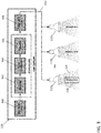
- an aircraft cabin 200 is illustrated according to a non-limiting embodiment.
- the aircraft cabin 200 includes a plurality of light emitting devices 112a-112n that output an ID signal 202 generated by modulating the emitted light at a predetermined frequency.
- the light can be pulsated at a frequency that ensures a stroboscopic effect (e.g., direct or indirect flicker) is not realized by the humans.
- Flight crew operators 204 are authorized to possess various wireless devices 106 (e.g., computer tablets, laptops, etc.) that are configured to receive a WAIC adapter 104.
- the WAIC adapter 104 and/or the wireless device 106 can detect the ID signal 202 output from the light emitting devices 112a-112n, and determine whether it is operating in an authorized area, i.e., within the aircraft cabin 200.
- the WAIC adapter 104 can detect the ID signal 202 when it is located within the cabin, but is unable to detect the ID signal 202 (i.e., the light emitted by the light emitting devices 112a-112n) when it is removed from a given area of the cabin 200 or from the aircraft completely.
- the WAIC adapter 104 can be activated and the wireless device 106 is capable of communicating with the communication network at the specified bandwidth frequency (e.g., 4.2 GHz to 4.4 GHz). Otherwise, the WAIC adapter 104 is deactivated thereby preventing the wireless device 106 from operating at the frequency (e.g., 4.2 GHz to 4.4 GHz) necessary to exchange data with the aircraft's communication network.
- the specified bandwidth frequency e.g., 4.2 GHz to 4.4 GHz
- the light controller 110 includes a memory unit 300, an encoding unit 302, a packet construction unit 304, a modulation unit 306, and a light signal driver 308. Any one of the encoding unit 302, packet construction unit 304, modulation unit 306, and light signal driver 308 can be constructed as an electronic hardware controller that includes memory and a processor configured to execute algorithms and computer-readable program instructions stored in the memory.
- the memory unit 300, encoding unit 302, packet construction unit 304, modulation unit 306, and light signal driver 308 can also be integrated together in a single hardware controller.
- the memory unit 302 is configured to store the ID pattern 114.
- the ID pattern can be represented as a sequence of binary values (e.g., 0's and 1's), or an ASCII representation, which can later be converted into its corresponding binary values.
- the ID pattern can correspond to the entire internal area (e.g., cockpit, passenger cabin, etc.).
- individual ID patterns can be stored in the memory unit 302, where each ID pattern corresponds to a particular area of the cabin. For instance, a first ID pattern may correspond to the cockpit, a second ID pattern may correspond to the first-class cabin area, a third ID pattern may correspond to the economy cabin area, etc.
- the encoding unit 302 is configured to encode the binary values into symbol sequences.
- the encoding unit converts the ASCII representation of the ID pattern into its corresponding binary values, and then converts the binary values into a sequence of encoded symbols.
- the packet construction unit 304 can then frame the encoded symbols into data packets based on a channel/line capacity.
- the modulation unit 306 is configured to modulate the data packets using various digital modulation techniques.
- the digital modulation techniques include, but are not limited to, On-Off Keying (OOK), OOK with Manchester encoding, Pulse Width Modulation (PWM), and OFDM (Orthogonal Frequency Division Multiplexing).
- the light signal driver 308 receives the modulated packets and generates a light driver signal 310 according to a set frequency.
- the light driver signal drives the light emitting devices 112a, 112b, 112n to generate a modulated pattern 118 of light pulses that the ID pattern 114 stored in the memory unit 300.
- the light emitting devices 112a, 112b, 112n are configured to emit light 116 that defines a modulated signal 118 indicative of the ID pattern 114 (i.e., stored in the memory unit 300) in response to the light driver signal 310.
- the light driver signal 310 causes the light emitting devices 112a, 112b, 112n to pulsate the light 116 at a frequency at which humans do not realize a stroboscopic effect (i.e., direct or indirect light flicker).
- the WAIC adapter 104 and/or the wireless device 106 includes an ID signal decoder system configured to convert the emitted light pulses 116 into a decoded binary pattern 400.
- the wireless device 106 e.g., PED
- the ID signal decoder system can be implemented in the WAIC adapter 104.
- one or more components of the ID signal decoder system can be implemented in the wireless device 106 while other components of the ID signal decoder can be implemented in the WAIC adapter 104.
- the ID signal decoder system includes a light detector device 402, a frame controller 404, an image processor 406, and a binary decoder circuit 408.
- the ID signal decoder system can operate according to a rolling shutter capturing technique to capture the frame/image of the pulsed light 116 in a row sequential manner as described in greater detail below.
- the light detector device 402 includes an electrical circuit configured to detect the light pulses 116 emitted from the at least one light emitting device 112a, 112b, 112n.
- the light detector device 402 can include, for example, an image sensor or camera.
- the frame controller 404 is in signal communication with the light detector device 402 and is configured to determine a data frame based on the light pulses 116.
- the data frame can include, for example, an amount of the light pulses 116 captured over a predetermined time period (e.g., 5 seconds).
- the image processor 406 is in signal communication with the frame controller 404. Accordingly, the image processor 406 processes one or more frames output from the frame controller 404, and determines a series of light and dark pulses corresponding to the emitted light pulses 116.
- the binary decoder circuit 408 is in signal communication with the image processor 406.
- the binary decoder circuit 408 is configured to determine the decoded binary pattern 400 based on the series of light and dark pulses included in the data frame, and generates a decoded binary signal 409 indicative of the decoded binary pattern 400.
- the decoded binary pattern 400 matches the modulated signal 118, which in turn matches the ID pattern 114 stored in the memory unit 300 of the light controller 110.
- the WAIC adapter 104 includes a location controller 410 and a WAIC circuit 412.
- the location controller 410 is configured to receive the decoded binary signal 409, and generates a control signal 416 based on the decoded binary pattern 400.
- the control signal 416 selectively activates or deactivates the WAIC circuit 412. When activated, the WAIC circuit 412 establishes communication with the communication network via an antenna 414.
- the location controller 410 includes memory that stores a secondary ID pattern intended to match the ID pattern 114 stored in the memory unit 300 of the light controller 110. Accordingly, the location controller 410 generates the control signal 416 to activate the WAIC circuit 412 in response to detecting a match between the decoded ID pattern 400 (obtained from the modulated ID pattern 118) and the stored secondary ID pattern. Therefore, the WAIC adapter 104 is not activated when the modulated ID pattern 118 indicated by the pulsed light 116 is not detected and/or when the modulated ID pattern 118 does not match the secondary ID pattern stored in the location controller 410.
- the control signal 416 deactivates the WAIC circuit 412, which allows the wireless device 106 to operate at the frequency band (e.g. the RA spectrum) specified by the communication network. In this manner, the wireless device 106 is determined to be operating in an authorized location, and is allowed to exchange data with the communication network.
- the frequency band e.g. the RA spectrum
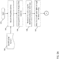
- the method begins at operation 500, and at operation 502 an ID pattern is obtained.
- the ID pattern can be stored in a memory unit and can be unique to an individual aircraft or can be unique to a particular area internal to the aircraft.
- the ID pattern is encoded, and at operation 506 the encoded symbols are framed into data packets based on a channel/line capacity.
- the data packets are modulated using various digital modulation techniques.
- a light driver signal is generated that drives the light emitting devices to generate a modulated pattern 118 of light pulses 116.
- the light driver signal drives the light emitting devices at a frequency at which a stroboscopic effect (e.g., direct or indirect flicker) is not realized by the humans.
- the light detection interruption event can occur, for example, when emitted light from a portable WAIC adapter location system is not detected or is poorly detected by a wireless device and/or a WAIC adapter connected to the wireless device.
- the method determines whether the light detection interruption event exceeds a threshold time limit at operation 514. When the light detection interruption event does not exceed the threshold time limit, the method returns to operation 512 and continues monitoring for a light detection interruption event. When, however, the light detection interruption event exceeds a threshold time limit, wireless communication between the wireless device and the aircraft communication network is blocked at operation 516.
- the wireless communication can be prevented by deactivating the WAIC adapter connected to the wireless device.
- the WAIC system e.g., a controller operating the WAIC system
- the WAIC system can assign the functionality originally assigned to the disconnected wireless device to a different or other available wireless device, and the operations described above can be applied to the other available wireless device.
- the method proceeds to operation 520 and detects the light emitted by the light emitting device interfaced with the WAIC adapter location system.
- the emitted light is captured as an image frame using an image sensor installed on the wireless device and/or the WAIC adapter.
- the captured image is processed to generate digital data, and the data is decoded at operation 524 to determine the ID pattern indicated by the emitted light.
- the decoded ID pattern is used to determine the location of the WAIC adapter and wireless device.
- wireless communication between the wireless device and the aircraft communication network is established at operation 530.
- the wireless communication can be established by activating the WAIC adapter connected to the wireless device. Accordingly, data generated by the wireless device is output at frequency bandwidth set by the communication network (e.g., the RA spectrum) such that the wireless device can exchange data with other systems, components, etc. connected to the communication network at operation 532.
- the communication network e.g., the RA spectrum
- the decoded ID pattern indicates that the WAIC adapter and wireless device are outside of an authorized communication area (e.g., outside the aircraft)
- wireless communication between the wireless device and the communication network is blocked at operation 516.
- the wireless communication can be prevented by deactivating the WAIC adapter connected to the wireless device.
- the WAIC system e.g., a controller operating the WAIC system
- the WAIC system can assign the functionality originally assigned to the disconnected wireless device to a different or other available wireless device, and the operations described above can be applied to the other available wireless device.
Landscapes
- Engineering & Computer Science (AREA)
- Computer Networks & Wireless Communication (AREA)
- Signal Processing (AREA)
- Physics & Mathematics (AREA)
- Electromagnetism (AREA)
- Astronomy & Astrophysics (AREA)
- Aviation & Aerospace Engineering (AREA)
- General Physics & Mathematics (AREA)
- Computing Systems (AREA)
- Optical Communication System (AREA)
- Mobile Radio Communication Systems (AREA)
Abstract
Description
- This application claims the benefit of Indian Application No.
201811038486 filed October 10, 2018 - Exemplary embodiments pertain to the art of aircraft communication systems, and more particularly, to Wireless Avionics Intra-Communication communication systems that employ portable wireless avionic devices.
- Replacing aircraft wired communication systems with wireless communication has gained wide-spread attention in aircraft designs due to its improvement on fuel efficiency of the aircraft and its load carrying capacity. A current aircraft wireless communication system referred to as "Wireless Avionics Intra-Communication" (WAIC) allows for reliable short-range radio communication links between two or more aircraft systems, sub-systems and/or wireless devices located on-board the same aircraft. WAIC operates according to the Radio Altimeter (RA) spectrum, which ranges from 4.2 gigahertz (GHz) to 4.4 GHz. The wireless devices typically utilized on board aircrafts such as off-the-shelf portable electronic devices (PEDs, for example, operate according to a different spectrum (e.g., about 2.4 GHz). Therefore, a WAIC adapter is utilized to allow these wireless devices to operate in the WAIC system.
- Disclosed is a Wireless Avionics Intra-Communication (WAIC) system comprising a communication network configured to exchange data with a portable wireless device, and a WAIC adapter location system configured to determine a location of a WAIC adapter. The WAIC adapter is configured to selectively connect and disconnect the portable device from the communication network based on the location.
- Also disclosed is a Wireless Avionics Intra-Communication (WAIC) adapter location system comprising a light controller configured to generate an identification (ID) pattern and to drive at least one light emitting device to emit a series of light pulses indicative of the ID pattern. The WAIC adapter location system further includes a WAIC adapter configured to selectively establish signal connection with a communication network when the WAIC adapter is at location that receives the light pulses.
- Also disclosed is a method of identifying a Wireless Avionics Intra-Communication (WAIC) adapter. The method comprises generating, via a light controller, an identification (ID) pattern, and driving at least one light emitting device to emit a series of light pulses indicative of the ID pattern. The method further comprises determining a location of the WAIC adapter based on the series of light pulses, and selectively exchanging data between the wireless device and the communication network in response to determining the WAIC adapter is located in an authorized location.
- The following descriptions should not be considered limiting in any way. With reference to the accompanying drawings, like elements are numbered alike:
-
FIG. 1 depicts a WAIC system according to a non-limiting embodiment; -
FIG. 2 illustrates an aircraft cabin installed with a portable WAIC adapter location system according to a non-limiting embodiment; -
FIG. 3 is a block diagram of a portable WAIC adapter location system according to a non-limiting embodiment; -
FIG 4 is a block diagram of a WAIC adapter installed on a portable electronic device according to a non-limiting embodiment; and -
FIGS. 5A and5B depict a flow diagram illustrating a method of detecting and controlling a WAIC adapter according to a non-limiting embodiment. - A detailed description of one or more embodiments of the disclosed apparatus and method are presented herein by way of exemplification and not limitation with reference to the Figures. The term "about" is intended to include the degree of error associated with measurement of the particular quantity based upon the equipment available at the time of filing the application.
- As described above, a WAIC adapter allows off-the-shelf PEDs (e.g., computer tablets) to function in a WAIC system. These WAIC adapters are typically portable and can be connected and disconnected to a PED operated by authorized aircraft personnel (e.g., the flight crew). Once connected to the PED, the WAIC adapter allows the PED to exchange data with various systems of the aircraft. To ensure that the data exchange is authorized, it is important to determine the location of the WAIC adapter and allow the WAIC adapter to operate only while located within the cabin of the aircraft.
- Various non-limiting embodiments described herein provides a portable WAIC adapter location system capable of determining a location of a WAIC adapter and controlling the operation of the WAIC adapter based on the determined location. In one or more embodiments, the WAIC adapter location system utilizes the cabin lighting system to output a modulated binary code that confirms whether the WAIC adapter is located in an authorized aircraft cabin. When authenticated, the WAIC adapter is activated to allow the PED to communicate with the WAIC. Otherwise, the WAIC adapter is deactivated, thereby preventing unauthorized communication with the WAIC.
- With reference now to
FIG. 1 , aWAIC system 100 is illustrated according to a non-limiting embodiment. The WAICsystem 100 includes a portable WAICadapter location system 102 configured to control a WAICadapter 104 installed on a PED 106. As described herein, the WAICadapter location system 102 determines whether the WAICadapter 104 is located at an authorized location (e.g., within the cabin of a given aircraft). When the WAICadapter location system 102 determines that the WAICadapter 104 is located in an authorized area (e.g., within the cabin of an authorized aircraft), theadapter 104 is activated and allows the PED 106 to communicate with the aircraft'scommunication network 108. Otherwise, the WAICadapter 104 is deactivated, thereby preventing data exchange between thePED 106 and thecommunication network 108. - The WAIC
adapter location system 102 includes alight controller 110 in signal communication with one or morelight emitting devices light controller 110 is configured to generate an identification (ID)pattern 114 and to output a light driver signal that drives thelight emitting devices light 116 according to theID pattern 114. - The
light emitting devices light emitting devices light 116 in a manner that serves as an ID signal indicative of theID pattern 114. The emitted ID signal includes a modulatedpattern 118 of light pulses matching theID pattern 114 that indicates an area at which the WAICadapter 104 is authorized to operate. - Referring to
FIG. 2 , for example, anaircraft cabin 200 is illustrated according to a non-limiting embodiment. Theaircraft cabin 200 includes a plurality oflight emitting devices 112a-112n that output anID signal 202 generated by modulating the emitted light at a predetermined frequency. For example, the light can be pulsated at a frequency that ensures a stroboscopic effect (e.g., direct or indirect flicker) is not realized by the humans. -
Flight crew operators 204 are authorized to possess various wireless devices 106 (e.g., computer tablets, laptops, etc.) that are configured to receive aWAIC adapter 104. The WAICadapter 104 and/or thewireless device 106 can detect theID signal 202 output from thelight emitting devices 112a-112n, and determine whether it is operating in an authorized area, i.e., within theaircraft cabin 200. For example, the WAICadapter 104 can detect theID signal 202 when it is located within the cabin, but is unable to detect the ID signal 202 (i.e., the light emitted by thelight emitting devices 112a-112n) when it is removed from a given area of thecabin 200 or from the aircraft completely. Accordingly, when theID signal 202 is detected and authenticated, the WAICadapter 104 can be activated and thewireless device 106 is capable of communicating with the communication network at the specified bandwidth frequency (e.g., 4.2 GHz to 4.4 GHz). Otherwise, the WAICadapter 104 is deactivated thereby preventing thewireless device 106 from operating at the frequency (e.g., 4.2 GHz to 4.4 GHz) necessary to exchange data with the aircraft's communication network. - Turning to
FIG. 3 , thelight controller 110 is illustrated in greater detail. Thelight controller 110 includes amemory unit 300, anencoding unit 302, apacket construction unit 304, amodulation unit 306, and alight signal driver 308. Any one of theencoding unit 302,packet construction unit 304,modulation unit 306, andlight signal driver 308 can be constructed as an electronic hardware controller that includes memory and a processor configured to execute algorithms and computer-readable program instructions stored in the memory. Thememory unit 300,encoding unit 302,packet construction unit 304,modulation unit 306, andlight signal driver 308 can also be integrated together in a single hardware controller. - The
memory unit 302 is configured to store theID pattern 114. The ID pattern can be represented as a sequence of binary values (e.g., 0's and 1's), or an ASCII representation, which can later be converted into its corresponding binary values. In at least one embodiment, the ID pattern can correspond to the entire internal area (e.g., cockpit, passenger cabin, etc.). In other embodiments, individual ID patterns can be stored in thememory unit 302, where each ID pattern corresponds to a particular area of the cabin. For instance, a first ID pattern may correspond to the cockpit, a second ID pattern may correspond to the first-class cabin area, a third ID pattern may correspond to the economy cabin area, etc. - The
encoding unit 302 is configured to encode the binary values into symbol sequences. In at least one embodiment, the encoding unit converts the ASCII representation of the ID pattern into its corresponding binary values, and then converts the binary values into a sequence of encoded symbols. Thepacket construction unit 304 can then frame the encoded symbols into data packets based on a channel/line capacity. - The
modulation unit 306 is configured to modulate the data packets using various digital modulation techniques. The digital modulation techniques include, but are not limited to, On-Off Keying (OOK), OOK with Manchester encoding, Pulse Width Modulation (PWM), and OFDM (Orthogonal Frequency Division Multiplexing). - The
light signal driver 308 receives the modulated packets and generates alight driver signal 310 according to a set frequency. In at least one embodiment, the light driver signal drives thelight emitting devices pattern 118 of light pulses that theID pattern 114 stored in thememory unit 300. - The
light emitting devices signal 118 indicative of the ID pattern 114 (i.e., stored in the memory unit 300) in response to thelight driver signal 310. In at least one embodiment, thelight driver signal 310 causes thelight emitting devices - Turning now to
FIG. 4 , theWAIC adapter 104 and the wireless device 106 (e.g. PED) are illustrated in greater detail. TheWAIC adapter 104 and/or thewireless device 106 includes an ID signal decoder system configured to convert the emittedlight pulses 116 into a decodedbinary pattern 400. In the example, illustrated inFIG. 4 , the wireless device 106 (e.g., PED) is implemented with the ID signal decoder system. It should be appreciated, however, that the ID signal decoder system can be implemented in theWAIC adapter 104. In other embodiments, one or more components of the ID signal decoder system can be implemented in thewireless device 106 while other components of the ID signal decoder can be implemented in theWAIC adapter 104. - The ID signal decoder system includes a
light detector device 402, aframe controller 404, animage processor 406, and abinary decoder circuit 408. The ID signal decoder system can operate according to a rolling shutter capturing technique to capture the frame/image of the pulsed light 116 in a row sequential manner as described in greater detail below. - The
light detector device 402 includes an electrical circuit configured to detect thelight pulses 116 emitted from the at least one light emittingdevice light detector device 402 can include, for example, an image sensor or camera. - The
frame controller 404 is in signal communication with thelight detector device 402 and is configured to determine a data frame based on thelight pulses 116. The data frame can include, for example, an amount of thelight pulses 116 captured over a predetermined time period (e.g., 5 seconds). - The
image processor 406 is in signal communication with theframe controller 404. Accordingly, theimage processor 406 processes one or more frames output from theframe controller 404, and determines a series of light and dark pulses corresponding to the emittedlight pulses 116. - The
binary decoder circuit 408 is in signal communication with theimage processor 406. Thebinary decoder circuit 408 is configured to determine the decodedbinary pattern 400 based on the series of light and dark pulses included in the data frame, and generates a decodedbinary signal 409 indicative of the decodedbinary pattern 400. The decodedbinary pattern 400 matches the modulatedsignal 118, which in turn matches theID pattern 114 stored in thememory unit 300 of thelight controller 110. - The
WAIC adapter 104 includes alocation controller 410 and aWAIC circuit 412. Thelocation controller 410 is configured to receive the decodedbinary signal 409, and generates acontrol signal 416 based on the decodedbinary pattern 400. Thecontrol signal 416 selectively activates or deactivates theWAIC circuit 412. When activated, theWAIC circuit 412 establishes communication with the communication network via anantenna 414. - In at least one embodiment, the
location controller 410 includes memory that stores a secondary ID pattern intended to match theID pattern 114 stored in thememory unit 300 of thelight controller 110. Accordingly, thelocation controller 410 generates thecontrol signal 416 to activate theWAIC circuit 412 in response to detecting a match between the decoded ID pattern 400 (obtained from the modulated ID pattern 118) and the stored secondary ID pattern. Therefore, theWAIC adapter 104 is not activated when the modulatedID pattern 118 indicated by thepulsed light 116 is not detected and/or when the modulatedID pattern 118 does not match the secondary ID pattern stored in thelocation controller 410. When, however, the modulatedID pattern 118 does not match the secondary ID pattern stored in thelocation controller 410, thecontrol signal 416 deactivates theWAIC circuit 412, which allows thewireless device 106 to operate at the frequency band (e.g. the RA spectrum) specified by the communication network. In this manner, thewireless device 106 is determined to be operating in an authorized location, and is allowed to exchange data with the communication network. - Referring now to
FIGS. 5A and5B a method of detecting and controlling a WAIC adapter is illustrated according to a non-limiting embodiment. The method begins atoperation 500, and atoperation 502 an ID pattern is obtained. The ID pattern can be stored in a memory unit and can be unique to an individual aircraft or can be unique to a particular area internal to the aircraft. Atoperation 504, the ID pattern is encoded, and atoperation 506 the encoded symbols are framed into data packets based on a channel/line capacity. Atoperation 508, the data packets are modulated using various digital modulation techniques. Atoperation 510, a light driver signal is generated that drives the light emitting devices to generate a modulatedpattern 118 oflight pulses 116. In one or more embodiments, the light driver signal drives the light emitting devices at a frequency at which a stroboscopic effect (e.g., direct or indirect flicker) is not realized by the humans. - Turning to operation 512 (see
FIG. 5B ), a determination is made as to whether a light detection interruption event has occurred. The light detection interruption event can occur, for example, when emitted light from a portable WAIC adapter location system is not detected or is poorly detected by a wireless device and/or a WAIC adapter connected to the wireless device. When a light detection interruption event has occurred, the method determines whether the light detection interruption event exceeds a threshold time limit atoperation 514. When the light detection interruption event does not exceed the threshold time limit, the method returns tooperation 512 and continues monitoring for a light detection interruption event. When, however, the light detection interruption event exceeds a threshold time limit, wireless communication between the wireless device and the aircraft communication network is blocked atoperation 516. In at least one embodiment, the wireless communication can be prevented by deactivating the WAIC adapter connected to the wireless device. Atoperation 518, the WAIC system (e.g., a controller operating the WAIC system) can assign the functionality originally assigned to the disconnected wireless device to a different or other available wireless device, and the operations described above can be applied to the other available wireless device. - Referring back to
operation 512 and a light detection interruption event has not occurred, the method proceeds tooperation 520 and detects the light emitted by the light emitting device interfaced with the WAIC adapter location system. In at least one non-limiting embodiment, the emitted light is captured as an image frame using an image sensor installed on the wireless device and/or the WAIC adapter. Atoperation 522 the captured image is processed to generate digital data, and the data is decoded atoperation 524 to determine the ID pattern indicated by the emitted light. Atoperation 526, the decoded ID pattern is used to determine the location of the WAIC adapter and wireless device. When the decoded ID pattern indicates that the WAIC adapter and wireless device are located at an authorized communication area (e.g., inside the aircraft) atoperation 528, wireless communication between the wireless device and the aircraft communication network is established atoperation 530. In at least one embodiment, the wireless communication can be established by activating the WAIC adapter connected to the wireless device. Accordingly, data generated by the wireless device is output at frequency bandwidth set by the communication network (e.g., the RA spectrum) such that the wireless device can exchange data with other systems, components, etc. connected to the communication network atoperation 532. - When, however, the decoded ID pattern indicates that the WAIC adapter and wireless device are outside of an authorized communication area (e.g., outside the aircraft), wireless communication between the wireless device and the communication network is blocked at
operation 516. In at least one embodiment, the wireless communication can be prevented by deactivating the WAIC adapter connected to the wireless device. Atoperation 518, the WAIC system (e.g., a controller operating the WAIC system) can assign the functionality originally assigned to the disconnected wireless device to a different or other available wireless device, and the operations described above can be applied to the other available wireless device. - The terminology used herein is for the purpose of describing particular embodiments only and is not intended to be limiting of the present disclosure. As used herein, the singular forms "a", "an" and "the" are intended to include the plural forms as well, unless the context clearly indicates otherwise. It will be further understood that the terms "comprises" and/or "comprising," when used in this specification, specify the presence of stated features, integers, steps, operations, elements, and/or components, but do not preclude the presence or addition of one or more other features, integers, steps, operations, element components, and/or groups thereof.
- While the present disclosure has been described with reference to an exemplary embodiment or embodiments, it will be understood by those skilled in the art that various changes may be made and equivalents may be substituted for elements thereof without departing from the scope of the invention as defined by the claims. In addition, many modifications may be made to adapt a particular situation or material to the teachings of the present disclosure without departing from the scope of the claims. Therefore, it is intended that the present disclosure not be limited to the particular embodiment disclosed as the best mode contemplated for carrying out this present disclosure, but that the present disclosure will include all embodiments falling within the scope of the claims.
Claims (15)
- A Wireless Avionics Intra-Communication, WAIC, system, the WAIC system comprising:a communication network (108) configured to exchange data with a portable wireless device (106); anda WAIC adapter location system (102) configured to determine a location of a WAIC adapter (104), the WAIC adapter configured to selectively connect and disconnect the portable device from the communication network based on the location.
- The WAIC system of claim 1, wherein the WAIC adapter location system comprises a light controller (110) configured to generate an identification, ID, pattern, wherein the location of the WAIC adapter is determined based at least in part on the ID pattern.
- The WAIC system of claim 2, wherein the light controller generates a light driver signal that operates at least one light emitting device (112) according to the modulation frequency, wherein the location of the WAIC adapter is based at least in part on the operation of the at least one light emitting device.
- The WAIC system of claim 3, wherein the at least one light emitting device is configured to emit light that defines an ID signal indicative of the ID pattern in response to the light driver signal.
- The WAIC system of claim 4, wherein the WAIC adapter comprises:a location controller (410) configured to determine the ID pattern indicated by the emitted light; anda WAIC circuit configured to selectively establish signal communication with the communication network based on the ID pattern, and preferably wherein the location controller (410) stores a secondary ID pattern, and activates the WAIC circuit in response to detecting a match between the determined ID pattern and the secondary ID pattern.
- The WAIC system of claim 5, wherein the WAIC circuit deactivates the WAIC circuit in response to the ID pattern being different from the secondary ID pattern.
- A Wireless Avionics Intra-Communication, WAIC, adapter location system comprising:a light controller (110) configured to generate an identification, ID, pattern and to drive at least one light emitting device to emit a series of light pulses indicative of the ID pattern; anda WAIC adapter (104) configured to selectively establish signal connection with a communication network when the WAIC adapter is at location that receives the light pulses.
- The WAIC adapter location system of claim 7, wherein the light controller comprises:a memory unit (300) configured to store the ID pattern;an encoding unit (302) configured to convert the ID pattern into encoded symbol sequences;a packet construction unit (304) configured to frame the encoded symbol sequences into data packets;a modulation unit (306) configured to modulate the data packets according to a modulation frequency; anda light signal driver (308) configured to generate a light driver signal that drives the at least one light emitting device according to the modulation frequency.
- The WAIC adapter location system of claim 8, wherein the WAIC adapter comprises:a location controller (410) configured to determine the ID pattern indicated by the light pulses; anda WAIC circuit (412) configured to selectively establish signal communication with the communication network based on the ID pattern.
- The WAIC adapter location system of claim 9, wherein the location controller (410) stores a secondary ID pattern, and activates the WAIC circuit (412) in response to detecting a match between the determined ID pattern and the secondary ID pattern, and preferably wherein the WAIC circuit (412) automatically deactivates the WAIC circuit in response to the ID pattern being different from the secondary ID pattern.
- A method of identifying a Wireless Avionics Intra-Communication, WAIC, adapter, the method comprising:generating, via a light controller, an identification, ID, pattern;driving at least one light emitting device to emit a series of light pulses indicative of the ID pattern; anddetermining a location of the WAIC adapter based on the series of light pulses; andselectively exchanging data between the wireless device and the communication network in response to determining the WAIC adapter is located in an authorized location.
- The method of claim 11, further comprising determining a match between the ID pattern indicated by the light pulses and a secondary ID pattern to determine the WAIC adapter is located in the authorized location.
- The method of claim 12, wherein driving the at least one light emitting device comprises:storing the ID pattern in a memory unit included in the light controller;converting, via an encoding unit, the ID pattern into encoded symbol sequences;framing, via a packet construction unit the encoded symbol sequences into data packets;modulating, via a modulation unit, the data packets according to a modulation frequency; andgenerating, via a light signal driver, a light driver signal that drives the at least one light emitting device according to the modulation frequency to generate the ID pattern.
- The method of claim 13, further comprising:determining, via the WAIC adapter, the ID pattern indicated by the emitted light; andselectively establishing a signal communication between the wireless device and the communication network, via the WAIC adapter, based on the ID pattern.
- The method of claim 14, wherein selectively establishing the signal communication comprises:generating a control signal, via a location controller included in the WAIC adapter, based on a comparison between the ID pattern and the secondary ID pattern;selectively activating a WAIC circuit included in the WAIC adapter based on the control signal; andin response to activating the WAIC circuit, operating the wireless device at a frequency band set by the communication network, and preferably wherein selectively establishing the signal communication further comprises automatically deactivating the WAIC circuit in response to the ID pattern being different from the secondary ID pattern.
Applications Claiming Priority (1)
| Application Number | Priority Date | Filing Date | Title |
|---|---|---|---|
| IN201811038486 | 2018-10-10 |
Publications (2)
| Publication Number | Publication Date |
|---|---|
| EP3637638A1 true EP3637638A1 (en) | 2020-04-15 |
| EP3637638B1 EP3637638B1 (en) | 2024-11-27 |
Family
ID=68158983
Family Applications (1)
| Application Number | Title | Priority Date | Filing Date |
|---|---|---|---|
| EP19201559.2A Active EP3637638B1 (en) | 2018-10-10 | 2019-10-04 | Portable wireless avionics intra-communication adapter location system and method |
Country Status (4)
| Country | Link |
|---|---|
| US (1) | US11146931B2 (en) |
| EP (1) | EP3637638B1 (en) |
| BR (1) | BR102019021123A2 (en) |
| CA (1) | CA3057233A1 (en) |
Cited By (1)
| Publication number | Priority date | Publication date | Assignee | Title |
|---|---|---|---|---|
| CN113613205A (en) * | 2021-07-11 | 2021-11-05 | 西北工业大学 | Network access mechanism suitable for wireless avionics internal communication network |
Families Citing this family (2)
| Publication number | Priority date | Publication date | Assignee | Title |
|---|---|---|---|---|
| US20220303004A1 (en) * | 2019-08-07 | 2022-09-22 | Nippon Telegraph And Telephone Corporation | Wireless communication system, wireless terminal equipment, wireless base station equipment and wireless communication methods |
| GB2605603B (en) * | 2021-04-06 | 2023-11-29 | Purelifi Ltd | Optical wireless communication system network separation |
Citations (4)
| Publication number | Priority date | Publication date | Assignee | Title |
|---|---|---|---|---|
| US20160095045A1 (en) * | 2014-09-30 | 2016-03-31 | Airbus Operations Gmbh | Wireless access for a mobile terminal to functional domains |
| FR3030161A1 (en) * | 2014-12-16 | 2016-06-17 | Airbus Operations Sas | AIRCRAFT COMMUNICATION SYSTEM |
| US20170251365A1 (en) * | 2014-09-08 | 2017-08-31 | Purelifi Limited | Cyber security |
| US20180139202A1 (en) * | 2015-05-19 | 2018-05-17 | Telefonaktiebolaget Lm Ericsson (Publ) | Communications system, a station, a controller of a light source, and methods therein for authenticating the station to access a network |
Family Cites Families (7)
| Publication number | Priority date | Publication date | Assignee | Title |
|---|---|---|---|---|
| US6400482B1 (en) | 1998-04-15 | 2002-06-04 | Talking Lights, Llc | Communication system |
| US7103456B2 (en) * | 2004-04-12 | 2006-09-05 | Sagem Avionics, Inc. | PCMCIA card for remotely communicating and interfacing with aircraft condition monitoring systems |
| US7969297B2 (en) | 2008-05-14 | 2011-06-28 | Sony Ericsson Mobile Communications Ab | System and method for determining positioning information via modulated light |
| US8866391B2 (en) * | 2011-07-26 | 2014-10-21 | ByteLight, Inc. | Self identifying modulated light source |
| US10285248B2 (en) * | 2014-11-04 | 2019-05-07 | Signify Holding B.V. | Transmitter comprising a transmission queue and corresponding source device |
| WO2017026555A1 (en) | 2015-08-12 | 2017-02-16 | 엘지전자 주식회사 | Mobile terminal |
| US10382128B2 (en) * | 2015-08-12 | 2019-08-13 | Lg Electronics Inc. | Mobile terminal |
-
2019
- 2019-09-17 US US16/572,817 patent/US11146931B2/en active Active
- 2019-09-30 CA CA3057233A patent/CA3057233A1/en active Pending
- 2019-10-04 EP EP19201559.2A patent/EP3637638B1/en active Active
- 2019-10-08 BR BR102019021123A patent/BR102019021123A2/en unknown
Patent Citations (4)
| Publication number | Priority date | Publication date | Assignee | Title |
|---|---|---|---|---|
| US20170251365A1 (en) * | 2014-09-08 | 2017-08-31 | Purelifi Limited | Cyber security |
| US20160095045A1 (en) * | 2014-09-30 | 2016-03-31 | Airbus Operations Gmbh | Wireless access for a mobile terminal to functional domains |
| FR3030161A1 (en) * | 2014-12-16 | 2016-06-17 | Airbus Operations Sas | AIRCRAFT COMMUNICATION SYSTEM |
| US20180139202A1 (en) * | 2015-05-19 | 2018-05-17 | Telefonaktiebolaget Lm Ericsson (Publ) | Communications system, a station, a controller of a light source, and methods therein for authenticating the station to access a network |
Non-Patent Citations (2)
| Title |
|---|
| "Application of Optical Wireless Communications for Avionics", IP.COM JOURNAL, IP.COM INC., WEST HENRIETTA, NY, US, 30 August 2018 (2018-08-30), XP013179864, ISSN: 1533-0001 * |
| COGALAN TEZCAN ET AL: "Inflight Connectivity: Deploying Different Communication Networks inside an Aircraft", 2018 IEEE 87TH VEHICULAR TECHNOLOGY CONFERENCE (VTC SPRING), IEEE, 3 June 2018 (2018-06-03), pages 1 - 6, XP033377534, DOI: 10.1109/VTCSPRING.2018.8417707 * |
Cited By (2)
| Publication number | Priority date | Publication date | Assignee | Title |
|---|---|---|---|---|
| CN113613205A (en) * | 2021-07-11 | 2021-11-05 | 西北工业大学 | Network access mechanism suitable for wireless avionics internal communication network |
| CN113613205B (en) * | 2021-07-11 | 2023-06-13 | 西北工业大学 | A network entry mechanism suitable for wireless avionics internal communication network |
Also Published As
| Publication number | Publication date |
|---|---|
| US20200120460A1 (en) | 2020-04-16 |
| CA3057233A1 (en) | 2020-04-10 |
| US11146931B2 (en) | 2021-10-12 |
| BR102019021123A2 (en) | 2020-04-28 |
| EP3637638B1 (en) | 2024-11-27 |
Similar Documents
| Publication | Publication Date | Title |
|---|---|---|
| US11146931B2 (en) | Portable wireless avionics intra-communication adapter location system | |
| KR101350036B1 (en) | Device for fault diagnosis of electronic display and method for fault diagnosis of electronic display therefor | |
| EP3495775B1 (en) | Protocol for high integrity personal electronic device applications | |
| US11776437B2 (en) | System and method for wireless control of signs | |
| US7358987B2 (en) | Endoscope system | |
| EP3495774B1 (en) | Avionics server for high integrity tablet applications | |
| EP3495778B1 (en) | System and method for displaying critical aeronautical information on an uncertified display | |
| US20150349882A1 (en) | Wireless data communication using airborne lighting and ground support systems | |
| WO2017172094A1 (en) | Infrastructure-device status-verification system for automated vehicles | |
| US9818269B1 (en) | Status light data transmission | |
| CN111726916B (en) | Photodiagnosis and monitoring using wearable devices | |
| KR101482912B1 (en) | Electric sign control systems utilizing vision boards with uninterruptible power supply | |
| EP4290786B1 (en) | Information exchange using an event camera | |
| JPWO2016051468A1 (en) | Train monitoring system | |
| EP2996301B1 (en) | Multi-protocol product line integration system | |
| US20190130657A1 (en) | Communication module and occupancy counter | |
| EP3203731A1 (en) | Network camera capable of detecting signal strength of wireless network and method thereof | |
| GB2540799A (en) | Method of indicating a status of a device on an aircraft | |
| KR101483443B1 (en) | Intelligent apparatus for trnasmitting control signal and image data | |
| CN110097737B (en) | Real-time visualization early warning method and system for underground engineering structure risk | |
| KR100860357B1 (en) | Monitoring device and method of variable information signs | |
| EP3334253B1 (en) | Remote control method for lighting fixtures | |
| EP3618580A1 (en) | Transmission coding scheme for a lighting system | |
| US20160284171A1 (en) | Modulating brightness of optical element conveying human-discernible information to also convey machine-discernible information | |
| KR100600622B1 (en) | Multi-beam infrared sensor and its operation method |
Legal Events
| Date | Code | Title | Description |
|---|---|---|---|
| PUAI | Public reference made under article 153(3) epc to a published international application that has entered the european phase |
Free format text: ORIGINAL CODE: 0009012 |
|
| STAA | Information on the status of an ep patent application or granted ep patent |
Free format text: STATUS: THE APPLICATION HAS BEEN PUBLISHED |
|
| AK | Designated contracting states |
Kind code of ref document: A1 Designated state(s): AL AT BE BG CH CY CZ DE DK EE ES FI FR GB GR HR HU IE IS IT LI LT LU LV MC MK MT NL NO PL PT RO RS SE SI SK SM TR |
|
| AX | Request for extension of the european patent |
Extension state: BA ME |
|
| STAA | Information on the status of an ep patent application or granted ep patent |
Free format text: STATUS: REQUEST FOR EXAMINATION WAS MADE |
|
| 17P | Request for examination filed |
Effective date: 20201015 |
|
| RBV | Designated contracting states (corrected) |
Designated state(s): AL AT BE BG CH CY CZ DE DK EE ES FI FR GB GR HR HU IE IS IT LI LT LU LV MC MK MT NL NO PL PT RO RS SE SI SK SM TR |
|
| STAA | Information on the status of an ep patent application or granted ep patent |
Free format text: STATUS: EXAMINATION IS IN PROGRESS |
|
| 17Q | First examination report despatched |
Effective date: 20210510 |
|
| RAP1 | Party data changed (applicant data changed or rights of an application transferred) |
Owner name: ARINC INCORPORATED |
|
| GRAP | Despatch of communication of intention to grant a patent |
Free format text: ORIGINAL CODE: EPIDOSNIGR1 |
|
| STAA | Information on the status of an ep patent application or granted ep patent |
Free format text: STATUS: GRANT OF PATENT IS INTENDED |
|
| INTG | Intention to grant announced |
Effective date: 20240528 |
|
| GRAS | Grant fee paid |
Free format text: ORIGINAL CODE: EPIDOSNIGR3 |
|
| GRAA | (expected) grant |
Free format text: ORIGINAL CODE: 0009210 |
|
| STAA | Information on the status of an ep patent application or granted ep patent |
Free format text: STATUS: THE PATENT HAS BEEN GRANTED |
|
| AK | Designated contracting states |
Kind code of ref document: B1 Designated state(s): AL AT BE BG CH CY CZ DE DK EE ES FI FR GB GR HR HU IE IS IT LI LT LU LV MC MK MT NL NO PL PT RO RS SE SI SK SM TR |
|
| REG | Reference to a national code |
Ref country code: GB Ref legal event code: FG4D |
|
| REG | Reference to a national code |
Ref country code: CH Ref legal event code: EP |
|
| REG | Reference to a national code |
Ref country code: DE Ref legal event code: R096 Ref document number: 602019062504 Country of ref document: DE |
|
| REG | Reference to a national code |
Ref country code: IE Ref legal event code: FG4D |
|
| REG | Reference to a national code |
Ref country code: LT Ref legal event code: MG9D |
|
| REG | Reference to a national code |
Ref country code: NL Ref legal event code: MP Effective date: 20241127 |
|
| PG25 | Lapsed in a contracting state [announced via postgrant information from national office to epo] |
Ref country code: PT Free format text: LAPSE BECAUSE OF FAILURE TO SUBMIT A TRANSLATION OF THE DESCRIPTION OR TO PAY THE FEE WITHIN THE PRESCRIBED TIME-LIMIT Effective date: 20250327 Ref country code: IS Free format text: LAPSE BECAUSE OF FAILURE TO SUBMIT A TRANSLATION OF THE DESCRIPTION OR TO PAY THE FEE WITHIN THE PRESCRIBED TIME-LIMIT Effective date: 20250327 Ref country code: HR Free format text: LAPSE BECAUSE OF FAILURE TO SUBMIT A TRANSLATION OF THE DESCRIPTION OR TO PAY THE FEE WITHIN THE PRESCRIBED TIME-LIMIT Effective date: 20241127 |
|
| PG25 | Lapsed in a contracting state [announced via postgrant information from national office to epo] |
Ref country code: FI Free format text: LAPSE BECAUSE OF FAILURE TO SUBMIT A TRANSLATION OF THE DESCRIPTION OR TO PAY THE FEE WITHIN THE PRESCRIBED TIME-LIMIT Effective date: 20241127 Ref country code: NL Free format text: LAPSE BECAUSE OF FAILURE TO SUBMIT A TRANSLATION OF THE DESCRIPTION OR TO PAY THE FEE WITHIN THE PRESCRIBED TIME-LIMIT Effective date: 20241127 |
|
| REG | Reference to a national code |
Ref country code: AT Ref legal event code: MK05 Ref document number: 1746727 Country of ref document: AT Kind code of ref document: T Effective date: 20241127 |
|
| PG25 | Lapsed in a contracting state [announced via postgrant information from national office to epo] |
Ref country code: BG Free format text: LAPSE BECAUSE OF FAILURE TO SUBMIT A TRANSLATION OF THE DESCRIPTION OR TO PAY THE FEE WITHIN THE PRESCRIBED TIME-LIMIT Effective date: 20241127 |
|
| PG25 | Lapsed in a contracting state [announced via postgrant information from national office to epo] |
Ref country code: ES Free format text: LAPSE BECAUSE OF FAILURE TO SUBMIT A TRANSLATION OF THE DESCRIPTION OR TO PAY THE FEE WITHIN THE PRESCRIBED TIME-LIMIT Effective date: 20241127 |
|
| PG25 | Lapsed in a contracting state [announced via postgrant information from national office to epo] |
Ref country code: NO Free format text: LAPSE BECAUSE OF FAILURE TO SUBMIT A TRANSLATION OF THE DESCRIPTION OR TO PAY THE FEE WITHIN THE PRESCRIBED TIME-LIMIT Effective date: 20250227 |
|
| PG25 | Lapsed in a contracting state [announced via postgrant information from national office to epo] |
Ref country code: LV Free format text: LAPSE BECAUSE OF FAILURE TO SUBMIT A TRANSLATION OF THE DESCRIPTION OR TO PAY THE FEE WITHIN THE PRESCRIBED TIME-LIMIT Effective date: 20241127 Ref country code: AT Free format text: LAPSE BECAUSE OF FAILURE TO SUBMIT A TRANSLATION OF THE DESCRIPTION OR TO PAY THE FEE WITHIN THE PRESCRIBED TIME-LIMIT Effective date: 20241127 Ref country code: GR Free format text: LAPSE BECAUSE OF FAILURE TO SUBMIT A TRANSLATION OF THE DESCRIPTION OR TO PAY THE FEE WITHIN THE PRESCRIBED TIME-LIMIT Effective date: 20250228 |
|
| PG25 | Lapsed in a contracting state [announced via postgrant information from national office to epo] |
Ref country code: PL Free format text: LAPSE BECAUSE OF FAILURE TO SUBMIT A TRANSLATION OF THE DESCRIPTION OR TO PAY THE FEE WITHIN THE PRESCRIBED TIME-LIMIT Effective date: 20241127 |
|
| PG25 | Lapsed in a contracting state [announced via postgrant information from national office to epo] |
Ref country code: RS Free format text: LAPSE BECAUSE OF FAILURE TO SUBMIT A TRANSLATION OF THE DESCRIPTION OR TO PAY THE FEE WITHIN THE PRESCRIBED TIME-LIMIT Effective date: 20250227 |
|
| PG25 | Lapsed in a contracting state [announced via postgrant information from national office to epo] |
Ref country code: SM Free format text: LAPSE BECAUSE OF FAILURE TO SUBMIT A TRANSLATION OF THE DESCRIPTION OR TO PAY THE FEE WITHIN THE PRESCRIBED TIME-LIMIT Effective date: 20241127 |
|
| PG25 | Lapsed in a contracting state [announced via postgrant information from national office to epo] |
Ref country code: DK Free format text: LAPSE BECAUSE OF FAILURE TO SUBMIT A TRANSLATION OF THE DESCRIPTION OR TO PAY THE FEE WITHIN THE PRESCRIBED TIME-LIMIT Effective date: 20241127 |
|
| PG25 | Lapsed in a contracting state [announced via postgrant information from national office to epo] |
Ref country code: EE Free format text: LAPSE BECAUSE OF FAILURE TO SUBMIT A TRANSLATION OF THE DESCRIPTION OR TO PAY THE FEE WITHIN THE PRESCRIBED TIME-LIMIT Effective date: 20241127 |
|
| PG25 | Lapsed in a contracting state [announced via postgrant information from national office to epo] |
Ref country code: RO Free format text: LAPSE BECAUSE OF FAILURE TO SUBMIT A TRANSLATION OF THE DESCRIPTION OR TO PAY THE FEE WITHIN THE PRESCRIBED TIME-LIMIT Effective date: 20241127 |
|
| PG25 | Lapsed in a contracting state [announced via postgrant information from national office to epo] |
Ref country code: SK Free format text: LAPSE BECAUSE OF FAILURE TO SUBMIT A TRANSLATION OF THE DESCRIPTION OR TO PAY THE FEE WITHIN THE PRESCRIBED TIME-LIMIT Effective date: 20241127 |
|
| PG25 | Lapsed in a contracting state [announced via postgrant information from national office to epo] |
Ref country code: CZ Free format text: LAPSE BECAUSE OF FAILURE TO SUBMIT A TRANSLATION OF THE DESCRIPTION OR TO PAY THE FEE WITHIN THE PRESCRIBED TIME-LIMIT Effective date: 20241127 |
|
| PG25 | Lapsed in a contracting state [announced via postgrant information from national office to epo] |
Ref country code: IT Free format text: LAPSE BECAUSE OF FAILURE TO SUBMIT A TRANSLATION OF THE DESCRIPTION OR TO PAY THE FEE WITHIN THE PRESCRIBED TIME-LIMIT Effective date: 20241127 |
|
| REG | Reference to a national code |
Ref country code: DE Ref legal event code: R097 Ref document number: 602019062504 Country of ref document: DE |
|
| PG25 | Lapsed in a contracting state [announced via postgrant information from national office to epo] |
Ref country code: SE Free format text: LAPSE BECAUSE OF FAILURE TO SUBMIT A TRANSLATION OF THE DESCRIPTION OR TO PAY THE FEE WITHIN THE PRESCRIBED TIME-LIMIT Effective date: 20241127 |
|
| PLBE | No opposition filed within time limit |
Free format text: ORIGINAL CODE: 0009261 |
|
| STAA | Information on the status of an ep patent application or granted ep patent |
Free format text: STATUS: NO OPPOSITION FILED WITHIN TIME LIMIT |
|
| PGFP | Annual fee paid to national office [announced via postgrant information from national office to epo] |
Ref country code: GB Payment date: 20250923 Year of fee payment: 7 |
|
| PGFP | Annual fee paid to national office [announced via postgrant information from national office to epo] |
Ref country code: FR Payment date: 20250924 Year of fee payment: 7 |
|
| 26N | No opposition filed |
Effective date: 20250828 |
|
| PGFP | Annual fee paid to national office [announced via postgrant information from national office to epo] |
Ref country code: DE Payment date: 20250923 Year of fee payment: 7 |