EP3637600A1 - Tubular linear motor - Google Patents
Tubular linear motor Download PDFInfo
- Publication number
- EP3637600A1 EP3637600A1 EP18881194.7A EP18881194A EP3637600A1 EP 3637600 A1 EP3637600 A1 EP 3637600A1 EP 18881194 A EP18881194 A EP 18881194A EP 3637600 A1 EP3637600 A1 EP 3637600A1
- Authority
- EP
- European Patent Office
- Prior art keywords
- teeth
- peripheral edge
- linear motor
- core
- inner peripheral
- Prior art date
- Legal status (The legal status is an assumption and is not a legal conclusion. Google has not performed a legal analysis and makes no representation as to the accuracy of the status listed.)
- Granted
Links
Images






Classifications
-
- H—ELECTRICITY
- H02—GENERATION; CONVERSION OR DISTRIBUTION OF ELECTRIC POWER
- H02K—DYNAMO-ELECTRIC MACHINES
- H02K41/00—Propulsion systems in which a rigid body is moved along a path due to dynamo-electric interaction between the body and a magnetic field travelling along the path
- H02K41/02—Linear motors; Sectional motors
- H02K41/03—Synchronous motors; Motors moving step by step; Reluctance motors
- H02K41/031—Synchronous motors; Motors moving step by step; Reluctance motors of the permanent magnet type
-
- H—ELECTRICITY
- H02—GENERATION; CONVERSION OR DISTRIBUTION OF ELECTRIC POWER
- H02K—DYNAMO-ELECTRIC MACHINES
- H02K1/00—Details of the magnetic circuit
- H02K1/06—Details of the magnetic circuit characterised by the shape, form or construction
- H02K1/12—Stationary parts of the magnetic circuit
- H02K1/16—Stator cores with slots for windings
- H02K1/165—Shape, form or location of the slots
-
- H—ELECTRICITY
- H02—GENERATION; CONVERSION OR DISTRIBUTION OF ELECTRIC POWER
- H02K—DYNAMO-ELECTRIC MACHINES
- H02K2213/00—Specific aspects, not otherwise provided for and not covered by codes H02K2201/00 - H02K2211/00
- H02K2213/03—Machines characterised by numerical values, ranges, mathematical expressions or similar information
Definitions
- the present invention relates to a tubular linear motor.
- a tubular linear motor may include an armature provided with a core having a tubular yoke and a plurality of teeth arranged side-by-side in an axial direction on an outer periphery of the yoke, and with U-phase, V-phase, and W-phase windings which are mounted in slots between the teeth; and a movable element configured from a cylindrical base provided at an outer periphery of the armature and from a plurality of permanent magnets attached to an inner periphery of the base such that S poles and N poles are alternately arranged side-by-side in an axial direction (see Patent Literature 1, for example).
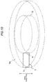
- teeth are provided on the outer periphery of the yoke, and the axial width of the teeth is equal, from the inner periphery to the outer periphery thereof. Furthermore, because the core has a cylindrical shape, if a cross section obtained by cutting the teeth T using a cylinder centered on the axis of the core is considered, the cross-sectional area of the teeth T has a minimum area Si at the inner peripheral edge ti (a surface obtained by cutting, at the outer periphery of the yoke, the boundary between the teeth and the yoke) of the teeth T, as illustrated in Fig. 10 .
- the cross-sectional area thereof is proportional to the size of the diameter and hence has a maximum area So at an outer peripheral edge to, a gradually decreasing area in moving from the outer peripheral edge to the inner peripheral side, and the minimum area Si at the inner peripheral edge ti.
- the magnetic circuit cross-sectional area of the teeth T is also maximum at the outer peripheral edge to of the teeth T and minimum at the inner peripheral edge ti of the teeth T.
- the magnetic circuit cross-sectional area at the inner peripheral edge ti of the teeth T is small, the magnetic flux is saturated at the inner peripheral edge ti, which has made obtaining a large thrust difficult.
- an object of the present invention is to provide a tubular linear motor capable of suppressing magnetic saturation to improve thrust.
- a tubular linear motor of the present invention includes a core that has a tubular yoke and a plurality of teeth which are annular and provided at intervals in an axial direction on an outer periphery of the yoke; a winding mounted in a slot between the teeth; and a field magnet that is tubular, into which the core is inserted movably in the axial direction, and having N poles and S poles alternately arranged in the axial direction, wherein an axial width of a yoke-side inner peripheral edge of the teeth is larger than an axial width of an outer peripheral edge of the teeth.
- the tubular linear motor M1 includes, as illustrated in Fig. 1 , a core 2 that has a tubular yoke 3 and a plurality of annular teeth 4 provided on an outer periphery of the yoke 3; a winding 5 mounted between the teeth 4, 4; and a field magnet 7 that is tubular and into which the core 2 is inserted movably in the axial direction.
- the core 2 includes a cylindrical yoke 3, and a plurality of teeth 4 which are annular and provided at intervals in an axial direction on the outer periphery of the yoke 3, and constitutes a movable element in the present embodiment.
- the yoke 3 is cylindrical as mentioned above and a wall thickness is secured such that, even when the teeth 4 are cut somewhere between the inner periphery and outer periphery thereof using a cylinder centered on an axis A of the core 2 (see Fig. 2 ), the cross-sectional area of the yoke 3 is equal to or larger than the area of the cross-section afforded when the teeth 4 are cut using the cylinder.
- ten teeth 4 are provided side-by-side at equal intervals in the axial direction on the outer periphery of the yoke 3, and a slot 6 constituting a gap into which the winding 5 is mounted is formed between the teeth 4, 4.
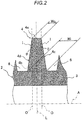
- the teeth 4 are each annular and have an inner peripheral edge 4b that has an axial width Wi larger than an axial width Wo of an outer peripheral edge 4a of the teeth 4. That is, the axial width Wi of the inner peripheral edge 4b of the teeth 4 is larger than the axial width Wo of the outer peripheral edge 4a of the teeth 4.
- an inclined surface I connected to the outer peripheral edge 4a is provided on the sides 4c, 4d of the teeth 4 on both sides in the axial direction. Furthermore, at the cross section obtained by cutting the teeth 4 in a plane containing the axis A of the core 2, an interior angle ⁇ formed between the inclined surface I and an orthogonal plane O orthogonal to the axis A of the core 2 is set at an angle in a range of six to twelve degrees.
- the cross-sectional shape obtained by cutting the teeth 4 in a plane containing axis A of the core 2 is a shape with line symmetry for which a line L orthogonal to the axis A of the core 2 is the axis of symmetry, as illustrated in Fig. 2 .
- a line that connects the center in the axial direction of the outer peripheral edge 4a of the teeth 4 to the center in the axial direction of the inner peripheral edge 4b of the teeth 4 geometrically coincides with the line L orthogonal to the axis A of the core 2, and the outer peripheral edge 4a, inner peripheral edge 4b, and sides 4c and 4d have a shape with line symmetry for which the line L is the axis of symmetry.
- a total of nine slots 6 constituting gaps are provided between the adjacent teeth 4, 4 in Fig. 1 .
- the winding 5 is mounted by being wound around the slots 6.
- W-phase, W-phase, W-phase, and V-phase, V-phase, V-phase, V-phase, and U-phase, U-phase, U-phase, U-phase, and W-phase windings 5 are mounted.
- the core 2 thus configured is mounted on the outer periphery of a rod 11 formed by a nonmagnetic body which is an output shaft. Specifically, the core 2 is fixed to the rod 11 as a result of the right and left ends of the core 2 in Fig. 1 being held by annular stoppers 12 and 13 which are fixed to the rod 11.
- a field magnet 7 includes, according to the present embodiment, an outer tube 8 formed from a cylindrical, nonmagnetic body, an inner tube 9 formed by a cylindrical, nonmagnetic body which is inserted inside the outer tube 8, and a plurality of permanent magnets 10 which are laminated in an axial direction and inserted throughout the annular gap between the outer tube 8 and inner tube 9.
- the core 2 is inserted movably in the axial direction inside the field magnet 7.
- the permanent magnets 10 are magnetized such that S poles and N poles are arranged alternately, in an axial direction, relative to the core 2 inserted on an inner peripheral side of the field magnet 7.
- S poles and N poles are arranged alternately in an axial direction on the inner peripheral side thereof such that a magnetic field is made to act on the core 2.
- the range over which the permanent magnets 10 are installed may be determined according to the range of movement of the core 2. Therefore, in the annular gap between the outer tube 8 and inner tube 9, the permanent magnets 10 need not be installed in areas where same are unable to oppose the core 2.
- the left ends in Fig. 1 of the outer tube 8 and inner tube 9 are closed by a cap 14, and the right ends in Fig. 1 of the outer tube 8 and inner tube 9 are closed by an annular rod guide 15 that guides the movement, in the axial direction, of the rod 11 inserted inside the inner periphery.
- the stoppers 12 and 13 are in sliding contact with the inner periphery of the inner tube 9, and the core 2 is capable of moving smoothly, together with the rod 11, in an axial direction without axial misalignment relative to the field magnet 7.
- the inner tube 9 forms a gap between the outer periphery of the core 2 and the outer periphery of the permanent magnets 10, and fulfills the role of guiding the axial movement of the core 2 in cooperation with the stoppers 12 and 13.
- the cap 14 is provided with a connector 14a that connects a cable C, which is connected to the winding 5, to an external power supply (not illustrated), thus enabling the winding 5 to be electrified by the external power supply.
- the axial length of the outer tube 8 and inner tube 9 is longer than the axial length of the core 2, and the core 2 is able to perform a stroke from left to right in Fig. 1 within the range of the axial length in the field magnet 7.
- the core 2 is an armature and a movable element, and the field magnet 7 behaves like a fixed element.
- the tubular linear motor M1 of the present invention includes a core 2 that has a tubular yoke 3 and a plurality of teeth 4 which are annular and provided at intervals in an axial direction on an outer periphery of the yoke 3; a winding 5 mounted in a slot 6 between the teeth 4, 4; and a field magnet 7 that is tubular, into which the core 2 is movably inserted in the axial direction, and having N poles and S poles alternately arranged in the axial direction, wherein an axial width Wi of a yoke-side inner peripheral edge 4b of the teeth 4 is larger than an axial width Wo of an outer peripheral edge 4a of the teeth 4.
- the axial width Wi of the inner peripheral edge 4b of the teeth 4 is larger than the axial width Wo of the outer peripheral edge 4a of the teeth 4.
- an area (the part shaded with solid lines) Ai of the inner peripheral edge 4b of the teeth 4 is then larger than an area (the part shaded with broken lines) Si of the inner peripheral edge of the teeth T of a conventional tubular linear motor.
- the tubular linear motor M1 of the present invention a magnetic circuit cross-sectional area which is large in comparison with a conventional tubular linear motor can be secured and magnetic saturation when the winding 5 is electrified can be suppressed, and hence a large magnetic field can be generated, thereby improving the thrust.
- the tubular linear motor M1 of the present invention enables thrust to be improved by suppressing magnetic saturation.
- the sides 4c and 4d of the cross section obtained by cutting the teeth 4 in a plane containing the axis A of the core 2 are shaped such that the edge of the outer peripheral edge 4a and the edge of the inner peripheral edge 4b are connected via a straight line.
- the thrust of the tubular linear motor M1 can be improved by suppressing magnetic saturation, and hence the shape of the sides 4c and 4d of the cross section obtained by cutting the teeth 4 in a plane containing the axis A of the core 2 is an arc shape or a parabola shape.
- the shape may also be such that the axial width of the teeth 4 becomes incrementally large at a midway point.
- the magnetic circuit cross-sectional area can be more readily secured than for the conventional tubular linear motor. Because the axial width in the radial direction of the teeth T of a conventional tubular linear motor is constant, the area Si of the inner peripheral edge of the teeth T is equal to an area obtained by multiplying the axial width Wo of the outer peripheral edge 4a of the teeth 4 of the tubular linear motor M1 according to the present embodiment by the circumference ⁇ ⁇ ⁇ i of the inner peripheral edge 4b of the teeth 4.
- the magnetic circuit cross-sectional area can be secured.
- the tubular linear motor M1 may include a core 2 that has a tubular yoke 3 and a plurality of teeth 4 which are annular and provided at intervals in an axial direction on an outer periphery of the yoke 3; a winding 5 mounted in a slot 6 between the teeth 4, 4; and a field magnet 7 that is tubular, into which the core 2 is movably inserted in the axial direction, and having N poles and S poles alternately arranged in the axial direction, wherein the area Ai of the inner peripheral edge 4b of the teeth 4 is larger than the area obtained by multiplying the axial width Wo of the outer peripheral edge 4a of the teeth 4 by the circumference ⁇ ⁇ ⁇ i of the inner peripheral edge 4b of the teeth 4.
- the tubular linear motor M1 Even when the tubular linear motor M1 is thus configured, because a larger magnetic circuit cross-sectional area than for a conventional tubular linear motor can be secured, magnetic saturation when the winding 5 is electrified can be suppressed, and a large magnetic field can be generated, thereby improving the thrust. Thus, the tubular linear motor M1 thus configured enables thrust to be improved by suppressing magnetic saturation. Note that, because the area Ai of the inner peripheral edge 4b of the teeth 4 only needs be larger than the area obtained by multiplying the axial width Wo of the outer peripheral edge 4a of the teeth 4 by the circumference ⁇ ⁇ ⁇ i of the inner peripheral edge 4b of the teeth 4, the shape of the teeth 4 can also be changed arbitrarily.
- the sides 4c and 4d of the teeth 4 on both sides in the axial direction are provided with the inclined surface I, and an interior angle ⁇ formed between the inclined surface I and the orthogonal plane O orthogonal to the axis A of the core 2 is an angle in a range of six to twelve degrees.
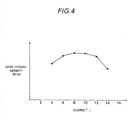
- the mass-thrust density when the interior angle ⁇ formed between the inclined surface I of the sides 4c and 4d of the cross section of the teeth 4 and the orthogonal plane O is changed is as illustrated in Fig. 4 .
- the mass-thrust density is a numerical value obtained by dividing the maximum thrust of the tubular linear motor M1 with the foregoing configuration by the mass.
- the interior angle ⁇ formed between the inclined surface I of the sides 4c and 4d of the cross section of the teeth 4 of the cross section of the teeth 4 and the orthogonal plane O is in a range of six to twelve degrees, it is clear that a favorable mass-thrust density is feasible.
- the interior angle ⁇ formed between the inclined surface I provided for the sides 4c and 4d of the teeth 4 on both sides in the axial direction and the orthogonal plane O orthogonal to the axis A of the core 2 is an angle in a range of six to twelve degrees, the thrust per mass of the tubular linear motor M1 is large, and hence a tubular linear motor M1 which is compact and yields a large thrust can be realized.
- the area of the inner peripheral edge 4b of the teeth 4 may be made equal to or larger than the area of the outer peripheral edge 4a of the teeth 4.
- the axial width of the inner peripheral edge 4b of the teeth 4 is Wo
- the axial width of the outer peripheral edge 4a of the teeth 4 is Wi
- the outside diameter of the teeth 4 is ⁇ o
- the inside diameter of the teeth 4 is ⁇ i.
- the area of the inner peripheral edge 4b of the teeth 4 can be made equal to or larger than the area of the outer peripheral edge 4a of the teeth 4.
- the cross-sectional area afforded when the teeth 4 are cut using a cylinder of any diameter centered on the axis A of the core 2 is made equal to or larger than the area Ao of the outer peripheral edge 4a of the teeth 4, it is possible to prevent the magnetic circuit cross-sectional area from resulting in a bottleneck at a midway point of the teeth 4.
- the cross section obtained by cutting the teeth 4 other than the teeth 4 at the ends of the core 2 in a plane containing axis A of the core 2 has a shape with line symmetry for which line L, which is orthogonal to the axis A of the core 2 and passes through the center in the axial direction of the teeth 4, is the axis of symmetry.
- the teeth 4 have a symmetrical shape in the axial direction centered on the axial center thereof, though the core 2 may be made to exert a thrust in any lateral direction in Fig. 1 relative to the field magnet 7, the amount of current in the winding 5 is equal for an identical thrust.
- the tubular linear motor M1 thus configured, there is no difference in polarity in the electrification amount of the winding 5 according to the driving direction of the tubular linear motor M1, and drive control is straightforward.
- the shape of the teeth 4 need not be a symmetrical shape in the axial direction centered on the axial center thereof.
- the cross-section obtained by cutting the teeth 4 in a plane containing the axis A of the core 2 has a shape with line symmetry for which the line L orthogonal to the axis A of the core 2 is the axis of symmetry and the sides 4c and 4d of the teeth 4 on both sides in the axial direction are provided with the inclined surface I, suitably setting the axial width Wo of the outer peripheral edge 4a of the teeth 4, the interior angle ⁇ formed between the inclined surface I and orthogonal plane O, and the outside diameter of the core 2 and the depth of the slot 6 enables the cross-sectional area afforded when the teeth 4 are cut using a cylinder of any diameter centered on the axis A of the core 2 to be made equal to or larger than the area Ao of the outer peripheral edge 4a of the teeth 4.
- the sides 4c and 4d of the teeth 4 on both sides in the axial direction are provided with the inclined surface I, suitably setting the axial width Wo of the outer peripheral edge 4a of the teeth 4, the interior angle ⁇ formed between the inclined surface I and orthogonal plane O, and the outside diameter of the core 2 and the depth of the slot 6 enables the core 2 to be formed by means of simple machining.
- the core 2 is manufactured by means of cutting in particular, machining is straightforward.
- the tubular linear motor M2 includes, as illustrated in Fig. 6 and similarly to the tubular linear motor 1 according to the first embodiment, a core 21 that has a tubular yoke 3 and a plurality of annular teeth 41 provided on an outer periphery of the yoke 3; a winding 5 mounted between the teeth 41, 41; and a field magnet 7 that is tubular and into which the core 21 is inserted movably in the axial direction.
- the tubular linear motor M2 according to the second embodiment differs from the tubular linear motor 1 according to the first embodiment in terms of the shape of the teeth 41 of the core 21.
- the teeth 41 will be described in detail hereinbelow.
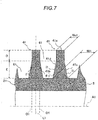
- the teeth 41 of the tubular linear motor M2 according to the second embodiment are annular and have an inner peripheral edge 41b with an axial width Wi1 which is larger than an axial width Wo1 of the outer peripheral edge 41a, as illustrated in Figs. 6 and 7 .
- the teeth 41 are shaped such that the axial width of the teeth 41 in a range D extending from the outer peripheral edge 41a to a depth midway toward the inner peripheral edge 41b is constant, and the axial width in a range E extending from the midway depth to the inner peripheral edge 41b of the deepest portion increases toward the inner peripheral edge 41b.
- the range D of sides 41c and 41d of the teeth 41 on both sides in the axial direction is a plane orthogonal to an axis A1 of the core 21
- the range E of the sides 41c and 41d of the teeth 41 on both sides in the axial direction is an inclined surface I1 that is inclined relative to the plane orthogonal to the axis of the core 21.
- an interior angle ⁇ 1 formed between the inclined surface I1 and an orthogonal plane O1 that is orthogonal to the axis A1 of the core 21 is set at an angle in a range of six to twelve degrees.
- the radial length of the teeth 41 in range D is shorter than the radial length of the teeth 41 in range E, and securing a large magnetic circuit cross-sectional area for the inner peripheral edge 41b of the teeth 41 may be considered.
- the cross-sectional shape obtained by cutting the teeth 41 in a plane containing axis A1 of the core 21 is a shape with line symmetry for which a line L1 orthogonal to the axis A1 of the core 21 is the axis of symmetry, as illustrated in Fig. 7 .
- a line that connects the center in the axial direction of the outer peripheral edge 41a of the teeth 41 to the center in the axial direction of the inner peripheral edge 41b of the teeth 41 geometrically coincides with the line L1 orthogonal to the axis A1 of the core 21, and the outer peripheral edge 41a, inner peripheral edge 41b, and sides 41c and 41d have a shape with line symmetry for which the line L1 is the axis of symmetry.
- the tubular linear motor M2 according to the second embodiment has a total of nine slots 61 constituting gaps provided between the adjacent teeth 41, 41 in Fig. 6 , and the winding 5 is mounted by being wound around the slots 61.
- the tubular linear motor M2 according to the second embodiment has W-phase, W-phase, W-phase, and V-phase, V-phase, V-phase, V-phase, and U-phase, U-phase, U-phase, U-phase, and W-phase windings 5, in order starting from the left side in Fig. 6 , mounted in nine slots 61.
- the tubular linear motor M2 of the present invention includes a core 21 that has a tubular yoke 3 and a plurality of teeth 41 which are annular and provided at intervals in an axial direction on an outer periphery of the yoke 3; a winding 5 mounted in a slot 61 between the teeth 41, 41; and a field magnet 7 that is tubular, into which the core 2 is movably inserted in the axial direction, and having N poles and S poles alternately arranged in the axial direction, wherein an axial width Wi1 of a yoke-side inner peripheral edge 41b of the teeth 4 is larger than an axial width Wo1 of an outer peripheral edge 41a of the teeth 41.
- the tubular linear motor M2 according to the present embodiment enables a magnetic circuit cross-sectional area which is large in comparison with a conventional tubular linear motor to be secured and magnetic saturation when the winding 5 is electrified to be suppressed, and hence a large magnetic field can be generated, thereby improving the thrust.
- the tubular linear motor M2 of the present invention enables thrust to be improved by suppressing magnetic saturation.
- the teeth 41 according to the present embodiment are shaped such that the axial width thereof in a range D extending from the outer peripheral edge 41a to a depth midway toward the inner peripheral edge 41b is constant, and the axial width in a range E extending from the midway depth to the inner peripheral edge 41b of the deepest portion increases toward the inner peripheral edge 41b.
- the teeth 41 are thus configured, the interval between the teeth 41, 41 on the outer peripheral edge 41a side of the teeth 41 widens. In other words, the width of the slots 61 on the outer peripheral edge 41a side of the teeth 41 increases, and the number of electrical wires of the winding 5 between range D of the teeth 41 and range D of adjacent teeth 41 is large.
- the winding 5 disposed in the part between the teeth 41, 41 on the outer peripheral edge 41a side lies opposite the field magnet 7 in the closest position to the field magnet 7, and the number of electrical wires of the winding 5 in this part has a significant effect on the thrust generated by the tubular linear motor M2, there being a tendency for the thrust to become large as the number of electrical wires of the winding 5 increases.
- the shape of the teeth 41 is a shape such that the axial width thereof in range D extending from the outer peripheral edge 41a to a depth midway toward the inner peripheral edge 41b is constant and that the axial width in range E extending from the midway depth to the inner peripheral edge 41b of the deepest portion increases toward the inner peripheral edge 41b, the number of electrical wires of the winding 5 arranged close to the field magnet 7 is increased while securing the magnetic circuit cross-sectional area.
- tubular linear motor M2 because the number of electrical wires of the winding 5 arranged close to the field magnet 7 is increased while securing the magnetic circuit cross-sectional area, it is possible to improve the mass-thrust density of the tubular linear motor M2. Moreover, by adopting the foregoing shape, machining of the teeth 41 is also straightforward.
- the outside diameter of the outer tube 8 of the tubular linear motor M2 is a diameter between 60 mm and 100 mm and that the outside diameter of the core 21 is a diameter between 50 mm and 83 mm
- setting an interior angle ⁇ 1 formed between the inclined surface I1 of the teeth 41 and the orthogonal plane O at about ten degrees makes it possible to achieve a balance between securing the magnetic circuit cross-sectional area of the teeth 41 and securing the number of electrical wires of the winding 5 arranged close to the field magnet 7, and is advantageous from the perspective of improving the mass-thrust density.
- the magnetic circuit cross-sectional area can be secured more readily than for a conventional tubular linear motor, and hence if the area of the inner peripheral edge 41b of the teeth 41 is made larger than the area obtained by multiplying the axial width Wo1 of the outer peripheral edge 41a of the teeth 41 by the circumference ⁇ ⁇ ⁇ i of the inner peripheral edge 41b of the teeth 41, the magnetic circuit cross-sectional area can be secured.
- the area of the inner peripheral edge 41b of the teeth 41 may be larger than the area obtained by multiplying the axial width Wo1 of the outer peripheral edge 41a of the teeth 41 by the circumference ⁇ ⁇ ⁇ i of the inner peripheral edge 41b of the teeth 41.
- the area of the inner peripheral edge 41b of the teeth 41 only needs to be larger than the area obtained by multiplying the axial width Wo1 of the outer peripheral edge 41a of the teeth 41 by the circumference ⁇ ⁇ ⁇ i of the inner peripheral edge 41b of the teeth 41, as long as the shape of the teeth 41 satisfies the conditions of a shape where the axial width thereof in range D extending from the outer peripheral edge 41a to a depth midway toward the inner peripheral edge 41b is constant and the axial width in range E extending from the midway depth to the inner peripheral edge 41b of the deepest portion increases toward the inner peripheral edge 41b, the shape can be arbitrarily changed.
- the radial length of the teeth 41 in range D is shorter than the radial length of the teeth 41 in range E, and it is possible to secure a large magnetic circuit cross-sectional area for the inner peripheral edge 41b of the teeth 41 even when the axial width of the teeth 41 in range D is fixed.
- the tubular linear motor M2 according to the present embodiment because the number of electrical wires of the winding 5 arranged close to the field magnet 7 is increased while also securing a large magnetic circuit cross-sectional area, it is possible to further improve the mass-thrust density of the tubular linear motor M2.
- the shape of the teeth 41 may be a shape such that range E to the inner peripheral edge 41b from the midway point of the sides 41c and 41d on both sides in the axial direction has the inclined surface I1 and such that interior angles ⁇ 2 and ⁇ 3 formed between the inclined surface I1 and the orthogonal plane O1 orthogonal to the axis A1 of the core 21 become incrementally large in moving from the midway point toward the inner peripheral edge 41b.
- the inclined surface I1 is shaped such that the angle of inclination changes at a midway point, and the interior angle ⁇ 3 on the inner peripheral side of the inclined surface I1 is larger than the interior angle ⁇ 2 on the outer peripheral side of the inclined surface I1.
- the interior angle ⁇ 2 is set at ten degrees
- the interior angle ⁇ 3 is set at thirty degrees.
- the shape of the teeth is a shape such that range E to the inner peripheral edge 41b from the midway point of the sides 41c and 41d on both sides in the axial direction has the inclined surface I1 and such that interior angles ⁇ 2 and ⁇ 3 formed between the inclined surface I1 and the orthogonal plane O1 orthogonal to the axis A1 of the core 21 become incrementally large in moving from the midway point toward the inner peripheral edge 41b, because the number of electrical wires of the winding 5 per slot 6 is increased while securing the magnetic circuit cross-sectional area of the teeth 41, it is possible to further improve the mass-thrust density of the tubular linear motor M2.
- the interior angle formed between the inclined surface I1 and the orthogonal plane O1 orthogonal to the axis A1 of the core 21 changes in two stages but may also change in three or more stages.
- the cross section obtained by cutting the teeth 41 other than the teeth 41 at the ends of the core 21 in a plane containing axis A1 of the core 21 has a shape with line symmetry for which line L1, which is orthogonal to the axis A1 of the core 21 and passes through the center in the axial direction of the teeth 41, is the axis of symmetry.
- the teeth 41 have a symmetrical shape in the axial direction centered on the axial center thereof, though the core 21 may be made to exert a thrust in any lateral direction relative to the field magnet 7, the amount of current in the winding 5 is equal for an identical thrust.
- the tubular linear motor M2 thus configured, there is no difference in polarity in the electrification amount of the winding 5 according to the driving direction of the tubular linear motor M2, and drive control is straightforward.
- the shape of the teeth 41 need not be a symmetrical shape in the axial direction centered on the axial center thereof.
Landscapes
- Engineering & Computer Science (AREA)
- Physics & Mathematics (AREA)
- Chemical & Material Sciences (AREA)
- Combustion & Propulsion (AREA)
- Electromagnetism (AREA)
- Power Engineering (AREA)
- Linear Motors (AREA)
Abstract
Description
- The present invention relates to a tubular linear motor.
- As disclosed in
JP 2008-253130 A - In the tubular linear motor thus configured, when the U-phase, V-phase, and W-phase windings of the armature are suitably electrified, the permanent magnets of the movable element are attracted, and the movable element is driven in an axial direction toward the armature.
- In the armature of the tubular linear motor, teeth are provided on the outer periphery of the yoke, and the axial width of the teeth is equal, from the inner periphery to the outer periphery thereof. Furthermore, because the core has a cylindrical shape, if a cross section obtained by cutting the teeth T using a cylinder centered on the axis of the core is considered, the cross-sectional area of the teeth T has a minimum area Si at the inner peripheral edge ti (a surface obtained by cutting, at the outer periphery of the yoke, the boundary between the teeth and the yoke) of the teeth T, as illustrated in
Fig. 10 . Because the axial width of the teeth T is constant, the cross-sectional area thereof is proportional to the size of the diameter and hence has a maximum area So at an outer peripheral edge to, a gradually decreasing area in moving from the outer peripheral edge to the inner peripheral side, and the minimum area Si at the inner peripheral edge ti. - Thus, the magnetic circuit cross-sectional area of the teeth T is also maximum at the outer peripheral edge to of the teeth T and minimum at the inner peripheral edge ti of the teeth T. In a conventional tubular linear motor of this kind, even when the winding is electrified, because the magnetic circuit cross-sectional area at the inner peripheral edge ti of the teeth T is small, the magnetic flux is saturated at the inner peripheral edge ti, which has made obtaining a large thrust difficult.
- Thus, an object of the present invention is to provide a tubular linear motor capable of suppressing magnetic saturation to improve thrust.
- To achieve the foregoing object, a tubular linear motor of the present invention includes a core that has a tubular yoke and a plurality of teeth which are annular and provided at intervals in an axial direction on an outer periphery of the yoke; a winding mounted in a slot between the teeth; and a field magnet that is tubular, into which the core is inserted movably in the axial direction, and having N poles and S poles alternately arranged in the axial direction, wherein an axial width of a yoke-side inner peripheral edge of the teeth is larger than an axial width of an outer peripheral edge of the teeth. In a tubular linear motor thus configured, a magnetic circuit cross-sectional area which is large in comparison with a conventional tubular linear motor can be secured, and magnetic saturation when the winding is electrified can be suppressed.
-
-
Fig. 1 is a vertical cross-sectional view of a tubular linear motor according to a first embodiment. -
Fig. 2 is a vertical cross-sectional view of a tooth part of the tubular linear motor according to the first embodiment. -
Fig. 3 is a diagram illustrating the difference between the area of the inner peripheral edge of the teeth of the tubular linear motor according to the first embodiment and the area of the inner peripheral edge of the teeth of a conventional tubular linear motor. -
Fig. 4 is a diagram illustrating the relationship between the mass-thrust density of the tubular linear motor according to the first embodiment and the interior angle formed between the inclined surface of the teeth and the orthogonal plane orthogonal to the axis of the core. -
Fig. 5 is a vertical cross-sectional view of a tooth part of a tubular linear motor according to a modification example of the first embodiment. -
Fig. 6 is a vertical cross-sectional view of a tubular linear motor according to a second embodiment. -
Fig. 7 is a vertical cross-sectional view of a tooth part of the tubular linear motor according to the second embodiment. -
Fig. 8 is a vertical cross-sectional view of a tooth part of a tubular linear motor according to a modification example of the second embodiment. -
Fig. 9 is a diagram illustrating the capacity of a slot in the tubular linear motor according to a modification example of the second embodiment. -
Fig. 10 is a diagram illustrating the areas of the inner peripheral edge and outer peripheral edge of the teeth of a conventional tubular linear motor. - The present invention will be described hereinbelow on the basis of embodiments illustrated in the drawings. Note that the same reference signs are assigned to configurations common to tubular linear motors M1 and M2 according to the respective embodiments described hereinbelow, and that detailed descriptions of configurations described in the description of the tubular linear motor M1 according to one embodiment are omitted from the description of the tubular linear motor M2 according to the other embodiment.
- The tubular linear motor M1 according to the first embodiment includes, as illustrated in
Fig. 1 , acore 2 that has atubular yoke 3 and a plurality ofannular teeth 4 provided on an outer periphery of theyoke 3; a winding 5 mounted between theteeth field magnet 7 that is tubular and into which thecore 2 is inserted movably in the axial direction. - Each part of the tubular linear motor M1 will be described in detail hereinbelow. The
core 2 includes acylindrical yoke 3, and a plurality ofteeth 4 which are annular and provided at intervals in an axial direction on the outer periphery of theyoke 3, and constitutes a movable element in the present embodiment. - The
yoke 3 is cylindrical as mentioned above and a wall thickness is secured such that, even when theteeth 4 are cut somewhere between the inner periphery and outer periphery thereof using a cylinder centered on an axis A of the core 2 (seeFig. 2 ), the cross-sectional area of theyoke 3 is equal to or larger than the area of the cross-section afforded when theteeth 4 are cut using the cylinder. - According to the present embodiment, as illustrated in
Figs. 1 and2 , tenteeth 4 are provided side-by-side at equal intervals in the axial direction on the outer periphery of theyoke 3, and aslot 6 constituting a gap into which thewinding 5 is mounted is formed between theteeth teeth 4 are each annular and have an innerperipheral edge 4b that has an axial width Wi larger than an axial width Wo of an outerperipheral edge 4a of theteeth 4. That is, the axial width Wi of the innerperipheral edge 4b of theteeth 4 is larger than the axial width Wo of the outerperipheral edge 4a of theteeth 4. - In addition, according to the present embodiment, as illustrated in
Fig. 2 , an inclined surface I connected to the outerperipheral edge 4a is provided on thesides teeth 4 on both sides in the axial direction. Furthermore, at the cross section obtained by cutting theteeth 4 in a plane containing the axis A of thecore 2, an interior angle θ formed between the inclined surface I and an orthogonal plane O orthogonal to the axis A of thecore 2 is set at an angle in a range of six to twelve degrees. - In addition, according to the present embodiment, except for the
teeth 4 arranged on the far left and far right inFig. 1 , the cross-sectional shape obtained by cutting theteeth 4 in a plane containing axis A of thecore 2 is a shape with line symmetry for which a line L orthogonal to the axis A of thecore 2 is the axis of symmetry, as illustrated inFig. 2 . In other words, a line that connects the center in the axial direction of the outerperipheral edge 4a of theteeth 4 to the center in the axial direction of the innerperipheral edge 4b of theteeth 4 geometrically coincides with the line L orthogonal to the axis A of thecore 2, and the outerperipheral edge 4a, innerperipheral edge 4b, andsides - In addition, according to the present embodiment, a total of nine
slots 6 constituting gaps are provided between theadjacent teeth Fig. 1 . Further, thewinding 5 is mounted by being wound around theslots 6. As the winding 5, W-phase, W-phase, W-phase, and V-phase, V-phase, V-phase, V-phase, and U-phase, U-phase, U-phase, U-phase, and W-phase windings 5 are mounted. - Furthermore, the
core 2 thus configured is mounted on the outer periphery of arod 11 formed by a nonmagnetic body which is an output shaft. Specifically, thecore 2 is fixed to therod 11 as a result of the right and left ends of thecore 2 inFig. 1 being held byannular stoppers rod 11. - Meanwhile, a
field magnet 7 includes, according to the present embodiment, anouter tube 8 formed from a cylindrical, nonmagnetic body, aninner tube 9 formed by a cylindrical, nonmagnetic body which is inserted inside theouter tube 8, and a plurality ofpermanent magnets 10 which are laminated in an axial direction and inserted throughout the annular gap between theouter tube 8 andinner tube 9. Thecore 2 is inserted movably in the axial direction inside thefield magnet 7. Thepermanent magnets 10 are magnetized such that S poles and N poles are arranged alternately, in an axial direction, relative to thecore 2 inserted on an inner peripheral side of thefield magnet 7. Accordingly, in thefield magnet 7, S poles and N poles are arranged alternately in an axial direction on the inner peripheral side thereof such that a magnetic field is made to act on thecore 2. Note that, because thefield magnet 7 only needs to cause a magnetic field to act on the range of movement of thecore 2, the range over which thepermanent magnets 10 are installed may be determined according to the range of movement of thecore 2. Therefore, in the annular gap between theouter tube 8 andinner tube 9, thepermanent magnets 10 need not be installed in areas where same are unable to oppose thecore 2. - In addition, the left ends in
Fig. 1 of theouter tube 8 andinner tube 9 are closed by acap 14, and the right ends inFig. 1 of theouter tube 8 andinner tube 9 are closed by anannular rod guide 15 that guides the movement, in the axial direction, of therod 11 inserted inside the inner periphery. Furthermore, thestoppers inner tube 9, and thecore 2 is capable of moving smoothly, together with therod 11, in an axial direction without axial misalignment relative to thefield magnet 7. Further, theinner tube 9 forms a gap between the outer periphery of thecore 2 and the outer periphery of thepermanent magnets 10, and fulfills the role of guiding the axial movement of thecore 2 in cooperation with thestoppers - Note that the
cap 14 is provided with aconnector 14a that connects a cable C, which is connected to the winding 5, to an external power supply (not illustrated), thus enabling the winding 5 to be electrified by the external power supply. Furthermore, the axial length of theouter tube 8 andinner tube 9 is longer than the axial length of thecore 2, and thecore 2 is able to perform a stroke from left to right inFig. 1 within the range of the axial length in thefield magnet 7. - Furthermore, for example, if the electrical angle of the
winding 5 relative to thefield magnet 7 is sensed, electrification phase switching is executed on the basis of the electrical angle, and the amount of current in eachwinding 5 is controlled using PWM control, it is possible to control the thrust of the tubular linear motor M1 and the movement direction of thecore 2. Note that the foregoing control method is an example and non-limiting. Thus, in the tubular linear motor M1 according to the present embodiment, thecore 2 is an armature and a movable element, and thefield magnet 7 behaves like a fixed element. Furthermore, in the event of an acting external force causing relative displacement of thecore 2 andfield magnet 7 in the axial direction, electrification of thewinding 5 or an induced electromotive force generated in thewinding 5 enables damping of device vibration or movement resulting from the external force on the tubular linear motor M1 by generating thrust to suppress the relative displacement, and also enables energy recovery in which electrical power is generated from the external force. - As described hereinabove, the tubular linear motor M1 of the present invention includes a
core 2 that has atubular yoke 3 and a plurality ofteeth 4 which are annular and provided at intervals in an axial direction on an outer periphery of theyoke 3; a winding 5 mounted in aslot 6 between theteeth field magnet 7 that is tubular, into which thecore 2 is movably inserted in the axial direction, and having N poles and S poles alternately arranged in the axial direction, wherein an axial width Wi of a yoke-side innerperipheral edge 4b of theteeth 4 is larger than an axial width Wo of an outerperipheral edge 4a of theteeth 4. - In the tubular linear motor M1 thus configured, the axial width Wi of the inner
peripheral edge 4b of theteeth 4 is larger than the axial width Wo of the outerperipheral edge 4a of theteeth 4. Thus, as illustrated inFig. 3 , if the axial width of the outer peripheral edge is equal to that of conventional teeth T (Wo = to), in comparison with conventional teeth T for which the axial width is constant, an area (the part shaded with solid lines) Ai of the innerperipheral edge 4b of theteeth 4 is then larger than an area (the part shaded with broken lines) Si of the inner peripheral edge of the teeth T of a conventional tubular linear motor. In other words, in the tubular linear motor M1 of the present invention, a magnetic circuit cross-sectional area which is large in comparison with a conventional tubular linear motor can be secured and magnetic saturation when thewinding 5 is electrified can be suppressed, and hence a large magnetic field can be generated, thereby improving the thrust. As detailed hereinabove, the tubular linear motor M1 of the present invention enables thrust to be improved by suppressing magnetic saturation. - Note that, in the foregoing example, the
sides teeth 4 in a plane containing the axis A of thecore 2 are shaped such that the edge of the outerperipheral edge 4a and the edge of the innerperipheral edge 4b are connected via a straight line. However, if the axial width Wi of the innerperipheral edge 4b of theteeth 4 is made larger than the axial width Wo of the outerperipheral edge 4a of theteeth 4, the thrust of the tubular linear motor M1 can be improved by suppressing magnetic saturation, and hence the shape of thesides teeth 4 in a plane containing the axis A of thecore 2 is an arc shape or a parabola shape. The shape may also be such that the axial width of theteeth 4 becomes incrementally large at a midway point. - In addition, as mentioned earlier, if the area Ai of the inner
peripheral edge 4b of theteeth 4 is made larger than the area Si of the inner peripheral edge of the teeth T of a conventional tubular linear motor, the magnetic circuit cross-sectional area can be more readily secured than for the conventional tubular linear motor. Because the axial width in the radial direction of the teeth T of a conventional tubular linear motor is constant, the area Si of the inner peripheral edge of the teeth T is equal to an area obtained by multiplying the axial width Wo of the outerperipheral edge 4a of theteeth 4 of the tubular linear motor M1 according to the present embodiment by the circumference π × ϕi of the innerperipheral edge 4b of theteeth 4. In other words, if the area Ai of the innerperipheral edge 4b of theteeth 4 is larger than an area obtained by multiplying the axial width Wo of the outerperipheral edge 4a of theteeth 4 by the circumference π × ϕi of the innerperipheral edge 4b of theteeth 4, the magnetic circuit cross-sectional area can be secured. Thus, the tubular linear motor M1 may include acore 2 that has atubular yoke 3 and a plurality ofteeth 4 which are annular and provided at intervals in an axial direction on an outer periphery of theyoke 3; a winding 5 mounted in aslot 6 between theteeth field magnet 7 that is tubular, into which thecore 2 is movably inserted in the axial direction, and having N poles and S poles alternately arranged in the axial direction, wherein the area Ai of the innerperipheral edge 4b of theteeth 4 is larger than the area obtained by multiplying the axial width Wo of the outerperipheral edge 4a of theteeth 4 by the circumference π × ϕi of the innerperipheral edge 4b of theteeth 4. Even when the tubular linear motor M1 is thus configured, because a larger magnetic circuit cross-sectional area than for a conventional tubular linear motor can be secured, magnetic saturation when the winding 5 is electrified can be suppressed, and a large magnetic field can be generated, thereby improving the thrust. Thus, the tubular linear motor M1 thus configured enables thrust to be improved by suppressing magnetic saturation. Note that, because the area Ai of the innerperipheral edge 4b of theteeth 4 only needs be larger than the area obtained by multiplying the axial width Wo of the outerperipheral edge 4a of theteeth 4 by the circumference π × ϕi of the innerperipheral edge 4b of theteeth 4, the shape of theteeth 4 can also be changed arbitrarily. - Furthermore, in the tubular linear motor M1 according to the present embodiment, the
sides teeth 4 on both sides in the axial direction are provided with the inclined surface I, and an interior angle θ formed between the inclined surface I and the orthogonal plane O orthogonal to the axis A of thecore 2 is an angle in a range of six to twelve degrees. If the structure of the tubular linear motor M1 is assumed, supposing that the outside diameter of theouter tube 8 of the tubular linear motor M1 according to the present embodiment is a diameter between 60 mm and 100 mm and the outside diameter of thecore 2 is a diameter between 50 mm and 83 mm, the mass-thrust density when the interior angle θ formed between the inclined surface I of thesides teeth 4 and the orthogonal plane O is changed is as illustrated inFig. 4 . Here, the mass-thrust density is a numerical value obtained by dividing the maximum thrust of the tubular linear motor M1 with the foregoing configuration by the mass. Thus, if the interior angle θ formed between the inclined surface I of thesides teeth 4 of the cross section of theteeth 4 and the orthogonal plane O is in a range of six to twelve degrees, it is clear that a favorable mass-thrust density is feasible. Based on the foregoing, when the interior angle θ formed between the inclined surface I provided for thesides teeth 4 on both sides in the axial direction and the orthogonal plane O orthogonal to the axis A of thecore 2 is an angle in a range of six to twelve degrees, the thrust per mass of the tubular linear motor M1 is large, and hence a tubular linear motor M1 which is compact and yields a large thrust can be realized. In other words, it is possible to realize a tubular linear motor M1 which is suitable for aircraft and vehicles in which there is no surplus installation space and which require a lightweight tubular linear motor. Note that, according to the present embodiment, although the inclined surface I occupies the whole of thesides teeth 4 on both sides in the axial direction, even if the inclined surface I is not used for a portion of thesides peripheral edge 4b of theteeth 4 as illustrated inFig. 5 , the advantageous effects of affording the tubular linear motor M1 compactness and a large thrust are not lost.Windings 5 with different phases need to be wound around some of theslots 6, and an even number of thesewindings 5 must be wound in the same array around theslots 6. Hence, even when thesides teeth 4 on both sides in the axial direction are provided with the inclined surface I, it may not be possible to provide the inclined surface I for thesides slots 6, that is, the base part of theteeth 4 connected to thecore 2. - Furthermore, the area of the inner
peripheral edge 4b of theteeth 4 may be made equal to or larger than the area of the outerperipheral edge 4a of theteeth 4. As illustrated inFig. 3 , suppose that the axial width of the innerperipheral edge 4b of theteeth 4 is Wo, the axial width of the outerperipheral edge 4a of theteeth 4 is Wi, the outside diameter of theteeth 4 is ϕo, and the inside diameter of theteeth 4 is ϕi. Thus, the area Ai of the innerperipheral edge 4b of theteeth 4 is then Ai = π × ϕi × Wi, and the area Ao of the outerperipheral edge 4a of theteeth 4 is then Ao = π × ϕo × Wo. Based on the foregoing, if the dimensions of the inside and outside diameters ϕi and ϕo and axial widths Wi and Wo of the innerperipheral edge 4b and outerperipheral edge 4a of theteeth 4 are configured so as to satisfy ϕo × Wo ≤ ϕi × Wi, the area of the innerperipheral edge 4b of theteeth 4 can be made equal to or larger than the area of the outerperipheral edge 4a of theteeth 4. In the tubular linear motor M1 thus configured, because it is possible to prevent the generation of magnetic saturation where the magnetic circuit cross-sectional area of the innerperipheral edge 4b of theteeth 4 becomes narrowest and results in a bottleneck, thrust can be improved more effectively. - In addition, if the cross-sectional area afforded when the
teeth 4 are cut using a cylinder of any diameter centered on the axis A of thecore 2 is made equal to or larger than the area Ao of the outerperipheral edge 4a of theteeth 4, it is possible to prevent the magnetic circuit cross-sectional area from resulting in a bottleneck at a midway point of theteeth 4. That is, if the cross-sectional area afforded when theteeth 4 are cut, in any position between the outerperipheral edge 4a and innerperipheral edge 4b of theteeth 4, using a cylinder of any diameter centered on the axis A of thecore 2 is made equal to or larger than the area Ao of the outerperipheral edge 4a, it is possible to prevent the magnetic circuit cross-sectional area from becoming minimal at a midway point of theteeth 4. Thus, with the tubular linear motor M1 thus configured, because the magnetic circuit cross-sectional area does not become small at a midway point of theteeth 4, thrust can be improved more effectively. - Note that, focusing on the magnetic circuit cross-sectional area alone, as long as all the cross-sectional areas, obtained by cutting in any position between the outer
peripheral edge 4a and innerperipheral edge 4b of theteeth 4 using a cylinder of any diameter centered on the axis A of thecore 2, are made equal, the magnetic circuit cross-sectional area cannot result in a bottleneck and there is no wastage, thereby affording the core 2 a lightweight mass. Note that, if the cross-sectional area obtained by cutting theyoke 3 in the orthogonal plane O orthogonal to the axis A of thecore 2 is also made equal to or larger than the area of the outerperipheral edge 4a of theteeth 4, a bottleneck in the magnetic circuit cross-sectional area is not generated by theyoke 3. - In addition, in the tubular linear motor M1 according to the present embodiment, the cross section obtained by cutting the
teeth 4 other than theteeth 4 at the ends of thecore 2 in a plane containing axis A of thecore 2 has a shape with line symmetry for which line L, which is orthogonal to the axis A of thecore 2 and passes through the center in the axial direction of theteeth 4, is the axis of symmetry. In the tubular linear motor M1 thus configured, because theteeth 4 have a symmetrical shape in the axial direction centered on the axial center thereof, though thecore 2 may be made to exert a thrust in any lateral direction inFig. 1 relative to thefield magnet 7, the amount of current in the winding 5 is equal for an identical thrust. Thus, with the tubular linear motor M1 thus configured, there is no difference in polarity in the electrification amount of the winding 5 according to the driving direction of the tubular linear motor M1, and drive control is straightforward. However, in a case such as where the thrust generation direction of the tubular linear motor M1 is unidirectional, or the like, if the occurrence of a polarity difference, according to driving direction, in the electrification amount of the winding 5 does not matter, the shape of theteeth 4 need not be a symmetrical shape in the axial direction centered on the axial center thereof. - Note that, if the cross-section obtained by cutting the
teeth 4 in a plane containing the axis A of thecore 2 has a shape with line symmetry for which the line L orthogonal to the axis A of thecore 2 is the axis of symmetry and thesides teeth 4 on both sides in the axial direction are provided with the inclined surface I, suitably setting the axial width Wo of the outerperipheral edge 4a of theteeth 4, the interior angle θ formed between the inclined surface I and orthogonal plane O, and the outside diameter of thecore 2 and the depth of theslot 6 enables the cross-sectional area afforded when theteeth 4 are cut using a cylinder of any diameter centered on the axis A of thecore 2 to be made equal to or larger than the area Ao of the outerperipheral edge 4a of theteeth 4. In other words, if thesides teeth 4 on both sides in the axial direction are provided with the inclined surface I, suitably setting the axial width Wo of the outerperipheral edge 4a of theteeth 4, the interior angle θ formed between the inclined surface I and orthogonal plane O, and the outside diameter of thecore 2 and the depth of theslot 6 enables thecore 2 to be formed by means of simple machining. When thecore 2 is manufactured by means of cutting in particular, machining is straightforward. - The tubular linear motor M2 according to the second embodiment includes, as illustrated in
Fig. 6 and similarly to the tubular linear motor 1 according to the first embodiment, a core 21 that has atubular yoke 3 and a plurality ofannular teeth 41 provided on an outer periphery of theyoke 3; a winding 5 mounted between theteeth field magnet 7 that is tubular and into which thecore 21 is inserted movably in the axial direction. - The tubular linear motor M2 according to the second embodiment differs from the tubular linear motor 1 according to the first embodiment in terms of the shape of the
teeth 41 of thecore 21. Theteeth 41 will be described in detail hereinbelow. Theteeth 41 of the tubular linear motor M2 according to the second embodiment are annular and have an innerperipheral edge 41b with an axial width Wi1 which is larger than an axial width Wo1 of the outerperipheral edge 41a, as illustrated inFigs. 6 and7 . Furthermore, theteeth 41 are shaped such that the axial width of theteeth 41 in a range D extending from the outerperipheral edge 41a to a depth midway toward the innerperipheral edge 41b is constant, and the axial width in a range E extending from the midway depth to the innerperipheral edge 41b of the deepest portion increases toward the innerperipheral edge 41b. - In addition, according to the present embodiment, as illustrated in
Fig. 7 , the range D ofsides teeth 41 on both sides in the axial direction is a plane orthogonal to an axis A1 of the core 21, and the range E of thesides teeth 41 on both sides in the axial direction is an inclined surface I1 that is inclined relative to the plane orthogonal to the axis of thecore 21. Furthermore, at the cross section obtained by cutting theteeth 41 in a plane containing the axis A1 of the core 21, an interior angle θ1 formed between the inclined surface I1 and an orthogonal plane O1 that is orthogonal to the axis A1 of thecore 21 is set at an angle in a range of six to twelve degrees. In addition, according to the present embodiment, the radial length of theteeth 41 in range D is shorter than the radial length of theteeth 41 in range E, and securing a large magnetic circuit cross-sectional area for the innerperipheral edge 41b of theteeth 41 may be considered. - Further, according to the present embodiment, except for the
teeth 41 arranged on the far left and far right inFig. 6 , the cross-sectional shape obtained by cutting theteeth 41 in a plane containing axis A1 of thecore 21 is a shape with line symmetry for which a line L1 orthogonal to the axis A1 of thecore 21 is the axis of symmetry, as illustrated inFig. 7 . In other words, a line that connects the center in the axial direction of the outerperipheral edge 41a of theteeth 41 to the center in the axial direction of the innerperipheral edge 41b of theteeth 41 geometrically coincides with the line L1 orthogonal to the axis A1 of the core 21, and the outerperipheral edge 41a, innerperipheral edge 41b, andsides - In addition, like the tubular linear motor M1 according to the first embodiment, the tubular linear motor M2 according to the second embodiment has a total of nine
slots 61 constituting gaps provided between theadjacent teeth Fig. 6 , and the winding 5 is mounted by being wound around theslots 61. Like the tubular linear motor M1 according to the first embodiment, the tubular linear motor M2 according to the second embodiment has W-phase, W-phase, W-phase, and V-phase, V-phase, V-phase, V-phase, and U-phase, U-phase, U-phase, U-phase, and W-phase windings 5, in order starting from the left side inFig. 6 , mounted in nineslots 61. - As described hereinabove, the tubular linear motor M2 of the present invention includes a core 21 that has a
tubular yoke 3 and a plurality ofteeth 41 which are annular and provided at intervals in an axial direction on an outer periphery of theyoke 3; a winding 5 mounted in aslot 61 between theteeth field magnet 7 that is tubular, into which thecore 2 is movably inserted in the axial direction, and having N poles and S poles alternately arranged in the axial direction, wherein an axial width Wi1 of a yoke-side innerperipheral edge 41b of theteeth 4 is larger than an axial width Wo1 of an outerperipheral edge 41a of theteeth 41. Thus, like the tubular linear motor 1 according to the first embodiment, the tubular linear motor M2 according to the present embodiment enables a magnetic circuit cross-sectional area which is large in comparison with a conventional tubular linear motor to be secured and magnetic saturation when the winding 5 is electrified to be suppressed, and hence a large magnetic field can be generated, thereby improving the thrust. As detailed hereinabove, the tubular linear motor M2 of the present invention enables thrust to be improved by suppressing magnetic saturation. - In addition, the
teeth 41 according to the present embodiment are shaped such that the axial width thereof in a range D extending from the outerperipheral edge 41a to a depth midway toward the innerperipheral edge 41b is constant, and the axial width in a range E extending from the midway depth to the innerperipheral edge 41b of the deepest portion increases toward the innerperipheral edge 41b. When theteeth 41 are thus configured, the interval between theteeth peripheral edge 41a side of theteeth 41 widens. In other words, the width of theslots 61 on the outerperipheral edge 41a side of theteeth 41 increases, and the number of electrical wires of the winding 5 between range D of theteeth 41 and range D ofadjacent teeth 41 is large. The winding 5 disposed in the part between theteeth peripheral edge 41a side lies opposite thefield magnet 7 in the closest position to thefield magnet 7, and the number of electrical wires of the winding 5 in this part has a significant effect on the thrust generated by the tubular linear motor M2, there being a tendency for the thrust to become large as the number of electrical wires of the winding 5 increases. Therefore, as per the present embodiment, supposing that the shape of theteeth 41 is a shape such that the axial width thereof in range D extending from the outerperipheral edge 41a to a depth midway toward the innerperipheral edge 41b is constant and that the axial width in range E extending from the midway depth to the innerperipheral edge 41b of the deepest portion increases toward the innerperipheral edge 41b, the number of electrical wires of the winding 5 arranged close to thefield magnet 7 is increased while securing the magnetic circuit cross-sectional area. Thus, with the tubular linear motor M2 according to the present embodiment, because the number of electrical wires of the winding 5 arranged close to thefield magnet 7 is increased while securing the magnetic circuit cross-sectional area, it is possible to improve the mass-thrust density of the tubular linear motor M2. Moreover, by adopting the foregoing shape, machining of theteeth 41 is also straightforward. - If the structure of the tubular linear motor M2 is assumed, supposing that the outside diameter of the
outer tube 8 of the tubular linear motor M2 according to the present embodiment is a diameter between 60 mm and 100 mm and that the outside diameter of thecore 21 is a diameter between 50 mm and 83 mm, setting an interior angle θ1 formed between the inclined surface I1 of theteeth 41 and the orthogonal plane O at about ten degrees makes it possible to achieve a balance between securing the magnetic circuit cross-sectional area of theteeth 41 and securing the number of electrical wires of the winding 5 arranged close to thefield magnet 7, and is advantageous from the perspective of improving the mass-thrust density. - Note that, if the area of the inner
peripheral edge 41b of theteeth 41 is larger than the area Si of the inner peripheral edge of the teeth T in a conventional tubular linear motor, the magnetic circuit cross-sectional area can be secured more readily than for a conventional tubular linear motor, and hence if the area of the innerperipheral edge 41b of theteeth 41 is made larger than the area obtained by multiplying the axial width Wo1 of the outerperipheral edge 41a of theteeth 41 by the circumference π × ϕi of the innerperipheral edge 41b of theteeth 41, the magnetic circuit cross-sectional area can be secured. Thus, the area of the innerperipheral edge 41b of theteeth 41 may be larger than the area obtained by multiplying the axial width Wo1 of the outerperipheral edge 41a of theteeth 41 by the circumference π × ϕi of the innerperipheral edge 41b of theteeth 41. Note that, because the area of the innerperipheral edge 41b of theteeth 41 only needs to be larger than the area obtained by multiplying the axial width Wo1 of the outerperipheral edge 41a of theteeth 41 by the circumference π × ϕi of the innerperipheral edge 41b of theteeth 41, as long as the shape of theteeth 41 satisfies the conditions of a shape where the axial width thereof in range D extending from the outerperipheral edge 41a to a depth midway toward the innerperipheral edge 41b is constant and the axial width in range E extending from the midway depth to the innerperipheral edge 41b of the deepest portion increases toward the innerperipheral edge 41b, the shape can be arbitrarily changed. - In addition, according to the present embodiment, the radial length of the
teeth 41 in range D is shorter than the radial length of theteeth 41 in range E, and it is possible to secure a large magnetic circuit cross-sectional area for the innerperipheral edge 41b of theteeth 41 even when the axial width of theteeth 41 in range D is fixed. Thus, with the tubular linear motor M2 according to the present embodiment, because the number of electrical wires of the winding 5 arranged close to thefield magnet 7 is increased while also securing a large magnetic circuit cross-sectional area, it is possible to further improve the mass-thrust density of the tubular linear motor M2. - Note that, as per the modification example illustrated in
Fig. 8 , the shape of theteeth 41 may be a shape such that range E to the innerperipheral edge 41b from the midway point of thesides peripheral edge 41b. - According to the present embodiment, the inclined surface I1 is shaped such that the angle of inclination changes at a midway point, and the interior angle θ3 on the inner peripheral side of the inclined surface I1 is larger than the interior angle θ2 on the outer peripheral side of the inclined surface I1.
- According to the present embodiment, the interior angle θ2 is set at ten degrees, and the interior angle θ3 is set at thirty degrees. Thus, when the shape is such that the interior angle formed between the inclined surface I1 and the orthogonal plane O1 becomes incrementally large in moving from the outer
peripheral edge 41a side toward the innerperipheral edge 41b side, if the width of the deepest portion of theslot 61 is made the same, as illustrated inFig. 9 , the capacity of theslot 61 is then large because the cross-sectional area of the shaded parts in the drawing increases in comparison with theteeth 41 for which the angle of the inclined surface I1 illustrated by the broken lines in the drawing is constant, thereby increasing the number of electrical wires of the winding 5 per slot. - Therefore, like the
teeth 41 in the modification example, if the shape of the teeth is a shape such that range E to the innerperipheral edge 41b from the midway point of thesides peripheral edge 41b, because the number of electrical wires of the winding 5 perslot 6 is increased while securing the magnetic circuit cross-sectional area of theteeth 41, it is possible to further improve the mass-thrust density of the tubular linear motor M2. - Note that, in the foregoing, the interior angle formed between the inclined surface I1 and the orthogonal plane O1 orthogonal to the axis A1 of the core 21 changes in two stages but may also change in three or more stages.
- In addition, in the tubular linear motor M2 according to the second embodiment, the cross section obtained by cutting the
teeth 41 other than theteeth 41 at the ends of the core 21 in a plane containing axis A1 of thecore 21 has a shape with line symmetry for which line L1, which is orthogonal to the axis A1 of thecore 21 and passes through the center in the axial direction of theteeth 41, is the axis of symmetry. In the tubular linear motor M2 thus configured, because theteeth 41 have a symmetrical shape in the axial direction centered on the axial center thereof, though the core 21 may be made to exert a thrust in any lateral direction relative to thefield magnet 7, the amount of current in the winding 5 is equal for an identical thrust. Thus, with the tubular linear motor M2 thus configured, there is no difference in polarity in the electrification amount of the winding 5 according to the driving direction of the tubular linear motor M2, and drive control is straightforward. However, in a case such as where the thrust generation direction of the tubular linear motor M2 is unidirectional, or the like, if the occurrence of a polarity difference, according to driving direction, in the electrification amount of the winding 5 does not matter, the shape of theteeth 41 need not be a symmetrical shape in the axial direction centered on the axial center thereof. - Although preferred embodiments of the present invention have been described in detail hereinabove, alterations, modifications and changes are possible without departing from the scope of the claims.
- The present application claims a right of priority on the basis of Japanese Patent Application No.
2017-225405 2018-197259
Claims (9)
- A tubular linear motor, comprising:a core that has a tubular yoke and a plurality of teeth which are annular and provided at intervals in an axial direction on an outer periphery of the yoke;a winding mounted in a slot between the teeth; anda field magnet that is tubular, into which the core is inserted movably in the axial direction, and having N poles and S poles alternately arranged in the axial direction,wherein an axial width of a yoke-side inner peripheral edge of the teeth is larger than an axial width of an outer peripheral edge of the teeth.
- The tubular linear motor as claimed in claim 1, comprising:a core that has a tubular yoke and a plurality of teeth which are annular and provided at intervals in an axial direction on an outer periphery of the yoke;a winding mounted in a slot between the teeth; anda field magnet that is tubular, into which the core is inserted movably in the axial direction, and having N poles and S poles alternately arranged in the axial direction,wherein the area of the inner peripheral edge of the teeth is larger than an area obtained by multiplying the axial width of the outer peripheral edge of the teeth by the circumference of the inner peripheral edge of the teeth.
- The tubular linear motor as claimed in claim 1,
wherein the area of the inner peripheral edge of the teeth is equal to or larger than the area of the outer peripheral edge of the teeth. - The tubular linear motor as claimed in claim 1,
wherein the cross-sectional area afforded when the teeth are cut using a cylinder centered on an axis of the core is equal to or larger than the area of the outer peripheral edge of the teeth. - The tubular linear motor as claimed in claim 1,
wherein the teeth are shaped such that an axial width thereof is constant in a range extending from the outer peripheral edge to a midway point toward the inner peripheral edge, and the axial width, in a range extending to the inner peripheral edge from the midway point, becomes increasingly large toward the inner peripheral edge. - The tubular linear motor as claimed in claim 1,
wherein the sides of the teeth on both sides in the axial direction have an inclined surface, and an interior angle formed between the inclined surface and an orthogonal plane orthogonal to an axis of the core is an angle in a range of six to twelve degrees. - The tubular linear motor as claimed in claim 5,
wherein the teeth have an inclined surface in a range extending to the inner peripheral edge from the midway point of the sides of the teeth on both sides in the axial direction, and an angle formed between the inclined surface and an orthogonal plane orthogonal to an axis of the core becomes incrementally large in moving from the midway point toward the inner peripheral edge. - The tubular linear motor as claimed in claim 5,
wherein a radial length in the range extending from the outer peripheral edge of the teeth to the midway point thereof is shorter than a radial length in a range extending from the inner peripheral edge of the teeth to the midway point thereof. - The tubular linear motor as claimed in claim 1,
wherein the cross section obtained by cutting the teeth in a plane containing the axis of the core is a shape with line symmetry for which a line orthogonal to the axis of the core is the axis of symmetry.
Applications Claiming Priority (3)
| Application Number | Priority Date | Filing Date | Title |
|---|---|---|---|
| JP2017225405 | 2017-11-24 | ||
| JP2018197259A JP7240569B2 (en) | 2017-11-24 | 2018-10-19 | Cylindrical linear motor |
| PCT/JP2018/039159 WO2019102761A1 (en) | 2017-11-24 | 2018-10-22 | Tubular linear motor |
Publications (3)
| Publication Number | Publication Date |
|---|---|
| EP3637600A1 true EP3637600A1 (en) | 2020-04-15 |
| EP3637600A4 EP3637600A4 (en) | 2021-03-03 |
| EP3637600B1 EP3637600B1 (en) | 2023-09-06 |
Family
ID=66972219
Family Applications (1)
| Application Number | Title | Priority Date | Filing Date |
|---|---|---|---|
| EP18881194.7A Active EP3637600B1 (en) | 2017-11-24 | 2018-10-22 | Tubular linear motor |
Country Status (3)
| Country | Link |
|---|---|
| US (1) | US11456654B2 (en) |
| EP (1) | EP3637600B1 (en) |
| JP (1) | JP7240569B2 (en) |
Families Citing this family (1)
| Publication number | Priority date | Publication date | Assignee | Title |
|---|---|---|---|---|
| US20230278434A1 (en) * | 2020-11-12 | 2023-09-07 | Terence Alan Tamutus | Capture arm system for magnetic levitation / road vehicle |
Family Cites Families (7)
| Publication number | Priority date | Publication date | Assignee | Title |
|---|---|---|---|---|
| JP2001199936A (en) * | 2000-01-19 | 2001-07-24 | Mitsubishi Chemicals Corp | Method for producing bis (meth) acrylate compound |
| TWI411199B (en) | 2007-03-08 | 2013-10-01 | Sanyo Electric Co | Linear motor |
| JP5452299B2 (en) * | 2010-03-17 | 2014-03-26 | 株式会社日立産機システム | Linear motor and its armature structure |
| JP5739254B2 (en) | 2011-07-08 | 2015-06-24 | オークマ株式会社 | Control device for synchronous motor |
| WO2014020695A1 (en) | 2012-07-31 | 2014-02-06 | 株式会社安川電機 | Linear motor |
| JP6304563B2 (en) * | 2015-06-05 | 2018-04-04 | 株式会社安川電機 | Linear motor and linear motor manufacturing method |
| JP6443303B2 (en) | 2015-11-05 | 2018-12-26 | トヨタ自動車株式会社 | Rotating electrical machine stator |
-
2018
- 2018-10-19 JP JP2018197259A patent/JP7240569B2/en active Active
- 2018-10-22 US US16/620,972 patent/US11456654B2/en active Active
- 2018-10-22 EP EP18881194.7A patent/EP3637600B1/en active Active
Also Published As
| Publication number | Publication date |
|---|---|
| JP2019097377A (en) | 2019-06-20 |
| EP3637600B1 (en) | 2023-09-06 |
| US20200212787A1 (en) | 2020-07-02 |
| EP3637600A4 (en) | 2021-03-03 |
| JP7240569B2 (en) | 2023-03-16 |
| US11456654B2 (en) | 2022-09-27 |
Similar Documents
| Publication | Publication Date | Title |
|---|---|---|
| EP3133724B1 (en) | Linear motor | |
| US20090001831A1 (en) | Axial Field Electric Motor and Method | |
| EP2712070B1 (en) | Linear vernier motor | |
| CN101911451B (en) | Linear stepping motor | |
| US20210313867A1 (en) | Tubular linear motor | |
| JP2020068624A (en) | Cylindrical linear motor | |
| EP3637600B1 (en) | Tubular linear motor | |
| JP5589507B2 (en) | Mover and stator of linear drive unit | |
| WO2019102761A1 (en) | Tubular linear motor | |
| JP6990143B2 (en) | Cylindrical linear motor | |
| JP2024159382A (en) | Cylindrical Linear Motor | |
| JP2023140403A (en) | Cylindrical linear motor | |
| JP2009194991A (en) | Linear motor and actuator | |
| US11245321B2 (en) | Cylindrical linear motor | |
| JP2019187212A (en) | Cylindrical linear motor | |
| JP2009005562A (en) | Linear motor | |
| JP2022012372A (en) | Tubular linear motor | |
| EP4535631A1 (en) | Cylindrical linear motor | |
| JP2025011486A (en) | Cylindrical Linear Motor | |
| KR20180086600A (en) | Linear Motor | |
| EP3076532A1 (en) | Linear motor | |
| JP7252834B2 (en) | Cylindrical linear motor | |
| JP2023121183A (en) | Cylindrical linear motor | |
| JP7036317B2 (en) | Cylindrical linear motor | |
| JP2023119627A (en) | Cylindrical linear motor |
Legal Events
| Date | Code | Title | Description |
|---|---|---|---|
| STAA | Information on the status of an ep patent application or granted ep patent |
Free format text: STATUS: THE INTERNATIONAL PUBLICATION HAS BEEN MADE |
|
| PUAI | Public reference made under article 153(3) epc to a published international application that has entered the european phase |
Free format text: ORIGINAL CODE: 0009012 |
|
| STAA | Information on the status of an ep patent application or granted ep patent |
Free format text: STATUS: REQUEST FOR EXAMINATION WAS MADE |
|
| 17P | Request for examination filed |
Effective date: 20200108 |
|
| AK | Designated contracting states |
Kind code of ref document: A1 Designated state(s): AL AT BE BG CH CY CZ DE DK EE ES FI FR GB GR HR HU IE IS IT LI LT LU LV MC MK MT NL NO PL PT RO RS SE SI SK SM TR |
|
| AX | Request for extension of the european patent |
Extension state: BA ME |
|
| A4 | Supplementary search report drawn up and despatched |
Effective date: 20210201 |
|
| DAV | Request for validation of the european patent (deleted) | ||
| DAX | Request for extension of the european patent (deleted) | ||
| RIC1 | Information provided on ipc code assigned before grant |
Ipc: H02K 1/16 20060101ALN20210126BHEP Ipc: H02K 41/03 20060101AFI20210126BHEP |
|
| GRAP | Despatch of communication of intention to grant a patent |
Free format text: ORIGINAL CODE: EPIDOSNIGR1 |
|
| STAA | Information on the status of an ep patent application or granted ep patent |
Free format text: STATUS: GRANT OF PATENT IS INTENDED |
|
| RIC1 | Information provided on ipc code assigned before grant |
Ipc: H02K 1/16 20060101ALN20230309BHEP Ipc: H02K 41/03 20060101AFI20230309BHEP |
|
| RIC1 | Information provided on ipc code assigned before grant |
Ipc: H02K 1/16 20060101ALN20230316BHEP Ipc: H02K 41/03 20060101AFI20230316BHEP |
|
| INTG | Intention to grant announced |
Effective date: 20230330 |
|
| GRAS | Grant fee paid |
Free format text: ORIGINAL CODE: EPIDOSNIGR3 |
|
| GRAA | (expected) grant |
Free format text: ORIGINAL CODE: 0009210 |
|
| STAA | Information on the status of an ep patent application or granted ep patent |
Free format text: STATUS: THE PATENT HAS BEEN GRANTED |
|
| AK | Designated contracting states |
Kind code of ref document: B1 Designated state(s): AL AT BE BG CH CY CZ DE DK EE ES FI FR GB GR HR HU IE IS IT LI LT LU LV MC MK MT NL NO PL PT RO RS SE SI SK SM TR |
|
| REG | Reference to a national code |
Ref country code: GB Ref legal event code: FG4D |
|
| REG | Reference to a national code |
Ref country code: CH Ref legal event code: EP |
|
| REG | Reference to a national code |
Ref country code: IE Ref legal event code: FG4D |
|
| REG | Reference to a national code |
Ref country code: DE Ref legal event code: R096 Ref document number: 602018057234 Country of ref document: DE |
|
| REG | Reference to a national code |
Ref country code: LT Ref legal event code: MG9D |
|
| REG | Reference to a national code |
Ref country code: NL Ref legal event code: MP Effective date: 20230906 |
|
| PG25 | Lapsed in a contracting state [announced via postgrant information from national office to epo] |
Ref country code: GR Free format text: LAPSE BECAUSE OF FAILURE TO SUBMIT A TRANSLATION OF THE DESCRIPTION OR TO PAY THE FEE WITHIN THE PRESCRIBED TIME-LIMIT Effective date: 20231207 |
|
| PG25 | Lapsed in a contracting state [announced via postgrant information from national office to epo] |
Ref country code: SE Free format text: LAPSE BECAUSE OF FAILURE TO SUBMIT A TRANSLATION OF THE DESCRIPTION OR TO PAY THE FEE WITHIN THE PRESCRIBED TIME-LIMIT Effective date: 20230906 Ref country code: RS Free format text: LAPSE BECAUSE OF FAILURE TO SUBMIT A TRANSLATION OF THE DESCRIPTION OR TO PAY THE FEE WITHIN THE PRESCRIBED TIME-LIMIT Effective date: 20230906 Ref country code: NO Free format text: LAPSE BECAUSE OF FAILURE TO SUBMIT A TRANSLATION OF THE DESCRIPTION OR TO PAY THE FEE WITHIN THE PRESCRIBED TIME-LIMIT Effective date: 20231206 Ref country code: LV Free format text: LAPSE BECAUSE OF FAILURE TO SUBMIT A TRANSLATION OF THE DESCRIPTION OR TO PAY THE FEE WITHIN THE PRESCRIBED TIME-LIMIT Effective date: 20230906 Ref country code: LT Free format text: LAPSE BECAUSE OF FAILURE TO SUBMIT A TRANSLATION OF THE DESCRIPTION OR TO PAY THE FEE WITHIN THE PRESCRIBED TIME-LIMIT Effective date: 20230906 Ref country code: HR Free format text: LAPSE BECAUSE OF FAILURE TO SUBMIT A TRANSLATION OF THE DESCRIPTION OR TO PAY THE FEE WITHIN THE PRESCRIBED TIME-LIMIT Effective date: 20230906 Ref country code: GR Free format text: LAPSE BECAUSE OF FAILURE TO SUBMIT A TRANSLATION OF THE DESCRIPTION OR TO PAY THE FEE WITHIN THE PRESCRIBED TIME-LIMIT Effective date: 20231207 Ref country code: FI Free format text: LAPSE BECAUSE OF FAILURE TO SUBMIT A TRANSLATION OF THE DESCRIPTION OR TO PAY THE FEE WITHIN THE PRESCRIBED TIME-LIMIT Effective date: 20230906 |
|
| REG | Reference to a national code |
Ref country code: AT Ref legal event code: MK05 Ref document number: 1609823 Country of ref document: AT Kind code of ref document: T Effective date: 20230906 |
|
| PG25 | Lapsed in a contracting state [announced via postgrant information from national office to epo] |
Ref country code: NL Free format text: LAPSE BECAUSE OF FAILURE TO SUBMIT A TRANSLATION OF THE DESCRIPTION OR TO PAY THE FEE WITHIN THE PRESCRIBED TIME-LIMIT Effective date: 20230906 |
|
| PG25 | Lapsed in a contracting state [announced via postgrant information from national office to epo] |
Ref country code: IS Free format text: LAPSE BECAUSE OF FAILURE TO SUBMIT A TRANSLATION OF THE DESCRIPTION OR TO PAY THE FEE WITHIN THE PRESCRIBED TIME-LIMIT Effective date: 20240106 |
|
| PG25 | Lapsed in a contracting state [announced via postgrant information from national office to epo] |
Ref country code: AT Free format text: LAPSE BECAUSE OF FAILURE TO SUBMIT A TRANSLATION OF THE DESCRIPTION OR TO PAY THE FEE WITHIN THE PRESCRIBED TIME-LIMIT Effective date: 20230906 |
|
| PG25 | Lapsed in a contracting state [announced via postgrant information from national office to epo] |
Ref country code: ES Free format text: LAPSE BECAUSE OF FAILURE TO SUBMIT A TRANSLATION OF THE DESCRIPTION OR TO PAY THE FEE WITHIN THE PRESCRIBED TIME-LIMIT Effective date: 20230906 |
|
| PG25 | Lapsed in a contracting state [announced via postgrant information from national office to epo] |
Ref country code: SM Free format text: LAPSE BECAUSE OF FAILURE TO SUBMIT A TRANSLATION OF THE DESCRIPTION OR TO PAY THE FEE WITHIN THE PRESCRIBED TIME-LIMIT Effective date: 20230906 Ref country code: RO Free format text: LAPSE BECAUSE OF FAILURE TO SUBMIT A TRANSLATION OF THE DESCRIPTION OR TO PAY THE FEE WITHIN THE PRESCRIBED TIME-LIMIT Effective date: 20230906 Ref country code: IS Free format text: LAPSE BECAUSE OF FAILURE TO SUBMIT A TRANSLATION OF THE DESCRIPTION OR TO PAY THE FEE WITHIN THE PRESCRIBED TIME-LIMIT Effective date: 20240106 Ref country code: ES Free format text: LAPSE BECAUSE OF FAILURE TO SUBMIT A TRANSLATION OF THE DESCRIPTION OR TO PAY THE FEE WITHIN THE PRESCRIBED TIME-LIMIT Effective date: 20230906 Ref country code: EE Free format text: LAPSE BECAUSE OF FAILURE TO SUBMIT A TRANSLATION OF THE DESCRIPTION OR TO PAY THE FEE WITHIN THE PRESCRIBED TIME-LIMIT Effective date: 20230906 Ref country code: CZ Free format text: LAPSE BECAUSE OF FAILURE TO SUBMIT A TRANSLATION OF THE DESCRIPTION OR TO PAY THE FEE WITHIN THE PRESCRIBED TIME-LIMIT Effective date: 20230906 Ref country code: AT Free format text: LAPSE BECAUSE OF FAILURE TO SUBMIT A TRANSLATION OF THE DESCRIPTION OR TO PAY THE FEE WITHIN THE PRESCRIBED TIME-LIMIT Effective date: 20230906 Ref country code: PT Free format text: LAPSE BECAUSE OF FAILURE TO SUBMIT A TRANSLATION OF THE DESCRIPTION OR TO PAY THE FEE WITHIN THE PRESCRIBED TIME-LIMIT Effective date: 20240108 Ref country code: SK Free format text: LAPSE BECAUSE OF FAILURE TO SUBMIT A TRANSLATION OF THE DESCRIPTION OR TO PAY THE FEE WITHIN THE PRESCRIBED TIME-LIMIT Effective date: 20230906 |
|
| PG25 | Lapsed in a contracting state [announced via postgrant information from national office to epo] |
Ref country code: PL Free format text: LAPSE BECAUSE OF FAILURE TO SUBMIT A TRANSLATION OF THE DESCRIPTION OR TO PAY THE FEE WITHIN THE PRESCRIBED TIME-LIMIT Effective date: 20230906 Ref country code: IT Free format text: LAPSE BECAUSE OF FAILURE TO SUBMIT A TRANSLATION OF THE DESCRIPTION OR TO PAY THE FEE WITHIN THE PRESCRIBED TIME-LIMIT Effective date: 20230906 |
|
| REG | Reference to a national code |
Ref country code: CH Ref legal event code: PL |
|
| REG | Reference to a national code |
Ref country code: DE Ref legal event code: R097 Ref document number: 602018057234 Country of ref document: DE |
|
| REG | Reference to a national code |
Ref country code: BE Ref legal event code: MM Effective date: 20231031 |
|
| PG25 | Lapsed in a contracting state [announced via postgrant information from national office to epo] |
Ref country code: LU Free format text: LAPSE BECAUSE OF NON-PAYMENT OF DUE FEES Effective date: 20231022 |
|
| PG25 | Lapsed in a contracting state [announced via postgrant information from national office to epo] |
Ref country code: LU Free format text: LAPSE BECAUSE OF NON-PAYMENT OF DUE FEES Effective date: 20231022 |
|
| PG25 | Lapsed in a contracting state [announced via postgrant information from national office to epo] |
Ref country code: MC Free format text: LAPSE BECAUSE OF FAILURE TO SUBMIT A TRANSLATION OF THE DESCRIPTION OR TO PAY THE FEE WITHIN THE PRESCRIBED TIME-LIMIT Effective date: 20230906 |
|
| PG25 | Lapsed in a contracting state [announced via postgrant information from national office to epo] |
Ref country code: DK Free format text: LAPSE BECAUSE OF FAILURE TO SUBMIT A TRANSLATION OF THE DESCRIPTION OR TO PAY THE FEE WITHIN THE PRESCRIBED TIME-LIMIT Effective date: 20230906 |
|
| PLBE | No opposition filed within time limit |
Free format text: ORIGINAL CODE: 0009261 |
|
| STAA | Information on the status of an ep patent application or granted ep patent |
Free format text: STATUS: NO OPPOSITION FILED WITHIN TIME LIMIT |
|
| PG25 | Lapsed in a contracting state [announced via postgrant information from national office to epo] |
Ref country code: CH Free format text: LAPSE BECAUSE OF NON-PAYMENT OF DUE FEES Effective date: 20231031 |
|
| PG25 | Lapsed in a contracting state [announced via postgrant information from national office to epo] |
Ref country code: MC Free format text: LAPSE BECAUSE OF FAILURE TO SUBMIT A TRANSLATION OF THE DESCRIPTION OR TO PAY THE FEE WITHIN THE PRESCRIBED TIME-LIMIT Effective date: 20230906 Ref country code: DK Free format text: LAPSE BECAUSE OF FAILURE TO SUBMIT A TRANSLATION OF THE DESCRIPTION OR TO PAY THE FEE WITHIN THE PRESCRIBED TIME-LIMIT Effective date: 20230906 Ref country code: CH Free format text: LAPSE BECAUSE OF NON-PAYMENT OF DUE FEES Effective date: 20231031 Ref country code: SI Free format text: LAPSE BECAUSE OF FAILURE TO SUBMIT A TRANSLATION OF THE DESCRIPTION OR TO PAY THE FEE WITHIN THE PRESCRIBED TIME-LIMIT Effective date: 20230906 |
|
| 26N | No opposition filed |
Effective date: 20240607 |
|
| GBPC | Gb: european patent ceased through non-payment of renewal fee |
Effective date: 20231206 |
|
| PG25 | Lapsed in a contracting state [announced via postgrant information from national office to epo] |
Ref country code: BE Free format text: LAPSE BECAUSE OF NON-PAYMENT OF DUE FEES Effective date: 20231031 |
|
| PG25 | Lapsed in a contracting state [announced via postgrant information from national office to epo] |
Ref country code: IE Free format text: LAPSE BECAUSE OF NON-PAYMENT OF DUE FEES Effective date: 20231022 |
|
| PG25 | Lapsed in a contracting state [announced via postgrant information from national office to epo] |
Ref country code: GB Free format text: LAPSE BECAUSE OF NON-PAYMENT OF DUE FEES Effective date: 20231206 |
|
| PG25 | Lapsed in a contracting state [announced via postgrant information from national office to epo] |
Ref country code: FR Free format text: LAPSE BECAUSE OF NON-PAYMENT OF DUE FEES Effective date: 20231106 |
|
| PG25 | Lapsed in a contracting state [announced via postgrant information from national office to epo] |
Ref country code: IE Free format text: LAPSE BECAUSE OF NON-PAYMENT OF DUE FEES Effective date: 20231022 Ref country code: GB Free format text: LAPSE BECAUSE OF NON-PAYMENT OF DUE FEES Effective date: 20231206 Ref country code: FR Free format text: LAPSE BECAUSE OF NON-PAYMENT OF DUE FEES Effective date: 20231106 |
|
| PG25 | Lapsed in a contracting state [announced via postgrant information from national office to epo] |
Ref country code: BG Free format text: LAPSE BECAUSE OF FAILURE TO SUBMIT A TRANSLATION OF THE DESCRIPTION OR TO PAY THE FEE WITHIN THE PRESCRIBED TIME-LIMIT Effective date: 20230906 |
|
| PG25 | Lapsed in a contracting state [announced via postgrant information from national office to epo] |
Ref country code: BG Free format text: LAPSE BECAUSE OF FAILURE TO SUBMIT A TRANSLATION OF THE DESCRIPTION OR TO PAY THE FEE WITHIN THE PRESCRIBED TIME-LIMIT Effective date: 20230906 |
|
| PG25 | Lapsed in a contracting state [announced via postgrant information from national office to epo] |
Ref country code: CY Free format text: LAPSE BECAUSE OF FAILURE TO SUBMIT A TRANSLATION OF THE DESCRIPTION OR TO PAY THE FEE WITHIN THE PRESCRIBED TIME-LIMIT; INVALID AB INITIO Effective date: 20181022 |
|
| PG25 | Lapsed in a contracting state [announced via postgrant information from national office to epo] |
Ref country code: HU Free format text: LAPSE BECAUSE OF FAILURE TO SUBMIT A TRANSLATION OF THE DESCRIPTION OR TO PAY THE FEE WITHIN THE PRESCRIBED TIME-LIMIT; INVALID AB INITIO Effective date: 20181022 |
|
| PG25 | Lapsed in a contracting state [announced via postgrant information from national office to epo] |
Ref country code: TR Free format text: LAPSE BECAUSE OF FAILURE TO SUBMIT A TRANSLATION OF THE DESCRIPTION OR TO PAY THE FEE WITHIN THE PRESCRIBED TIME-LIMIT Effective date: 20230906 |
|
| PGFP | Annual fee paid to national office [announced via postgrant information from national office to epo] |
Ref country code: DE Payment date: 20251021 Year of fee payment: 8 |