EP3637286A1 - Thermal analysis device, thermal analysis method, and thermal analysis program - Google Patents
Thermal analysis device, thermal analysis method, and thermal analysis program Download PDFInfo
- Publication number
- EP3637286A1 EP3637286A1 EP17912529.9A EP17912529A EP3637286A1 EP 3637286 A1 EP3637286 A1 EP 3637286A1 EP 17912529 A EP17912529 A EP 17912529A EP 3637286 A1 EP3637286 A1 EP 3637286A1
- Authority
- EP
- European Patent Office
- Prior art keywords
- thermal
- thermal analysis
- network model
- unit
- division number
- Prior art date
- Legal status (The legal status is an assumption and is not a legal conclusion. Google has not performed a legal analysis and makes no representation as to the accuracy of the status listed.)
- Withdrawn
Links
Images






Classifications
-
- G—PHYSICS
- G06—COMPUTING OR CALCULATING; COUNTING
- G06F—ELECTRIC DIGITAL DATA PROCESSING
- G06F30/00—Computer-aided design [CAD]
- G06F30/20—Design optimisation, verification or simulation
- G06F30/23—Design optimisation, verification or simulation using finite element methods [FEM] or finite difference methods [FDM]
-
- G—PHYSICS
- G06—COMPUTING OR CALCULATING; COUNTING
- G06F—ELECTRIC DIGITAL DATA PROCESSING
- G06F30/00—Computer-aided design [CAD]
-
- G—PHYSICS
- G06—COMPUTING OR CALCULATING; COUNTING
- G06F—ELECTRIC DIGITAL DATA PROCESSING
- G06F30/00—Computer-aided design [CAD]
- G06F30/20—Design optimisation, verification or simulation
-
- G—PHYSICS
- G06—COMPUTING OR CALCULATING; COUNTING
- G06F—ELECTRIC DIGITAL DATA PROCESSING
- G06F30/00—Computer-aided design [CAD]
- G06F30/30—Circuit design
-
- G—PHYSICS
- G06—COMPUTING OR CALCULATING; COUNTING
- G06F—ELECTRIC DIGITAL DATA PROCESSING
- G06F2111/00—Details relating to CAD techniques
- G06F2111/20—Configuration CAD, e.g. designing by assembling or positioning modules selected from libraries of predesigned modules
-
- G—PHYSICS
- G06—COMPUTING OR CALCULATING; COUNTING
- G06F—ELECTRIC DIGITAL DATA PROCESSING
- G06F2115/00—Details relating to the type of the circuit
- G06F2115/12—Printed circuit boards [PCB] or multi-chip modules [MCM]
-
- G—PHYSICS
- G06—COMPUTING OR CALCULATING; COUNTING
- G06F—ELECTRIC DIGITAL DATA PROCESSING
- G06F2119/00—Details relating to the type or aim of the analysis or the optimisation
- G06F2119/08—Thermal analysis or thermal optimisation
Definitions
- the present invention relates to a thermal analysis device, a thermal analysis method, and a thermal analysis program.
- thermal analysis can be performed in an upstream process in product design, a design guide can be easily made. To easily make the design guide, it is necessary to perform thermal analysis in a short time.
- an object of the present invention is to provide a thermal analysis device, a thermal analysis method, and a thermal analysis program capable of shortening time required for thermal analysis.
- a thermal analysis device includes an estimation unit that refers to a first storage unit that stores information regarding whether or not two components have contact with each other obtained from design information of a product in the past and estimates whether or not a component pair included in a target product has contact with each other, a determination unit that refers to a second storage unit that stores a relationship between a parameter regarding thermal transfer of the two components and the division number of a thermal network model and determines the division number of the thermal network model of the component pair included in the target product, and a thermal analysis unit that constructs the thermal network model of the target product by using an estimation result of the estimation unit and a determination result of the determination unit and performs thermal analysis.
- Time required for thermal analysis can be shortened.
- FIG. 1 a hardware configuration of a thermal analysis device 10 is illustrated.
- the thermal analysis device 10 is a Personal Computer (PC) and the like, and as illustrated in FIG. 1 , the thermal analysis device 10 includes a Central Processing Unit (CPU) 90, a Read Only Memory (ROM) 92, a Random Access Memory (RAM) 94, a storage unit (here, Hard Disk Drive (HDD)) 96, a network interface 97, a display unit 93, an input unit 95, a portable storage medium drive 99, and the like.
- Each component of the thermal analysis device 10 is connected to a bus 98.
- the display unit 93 includes a liquid crystal display and the like, and the input unit 95 includes a keyboard, a mouse, a touch panel, and the like.
- the CPU 90 executes a program (including thermal analysis program) stored in the ROM 92 or the HDD 96 or a program (including thermal analysis program) read from a portable storage medium 91 by the portable storage medium drive 99 so as to implement the function of each unit illustrated in FIG. 2 .
- a program including thermal analysis program
- a program including thermal analysis program
- a program including thermal analysis program
- a program including thermal analysis program
- the CPU 90 executes the program so as to implement functions of a contact determination model generation unit 30, a division method acquisition unit 32, a component data acquisition unit 12, an estimation model generation and output unit 14 as an estimation unit, a contact determination table acquisition unit 16, a tolerance acquisition unit 18 as a reception unit, a division number determination unit 20 as a determination unit, a thermal network model analysis unit 22 as a thermal analysis unit, and a learning unit 24 as an update unit illustrated in FIG. 2 .
- the contact determination model generation unit 30 acquires information regarding a past product stored in a design asset DB 40 and generates data of each component pair ( FIG. 3 ) based on the acquired information.
- the design asset DB 40 is a database that stores data similar to model data to be described later (refer to FIG. 9B ).
- the data of each component pair includes data of two components having contact with each other or facing each other in a product.
- the data of each component pair includes data of "component name 1" and “component name 2" that are names of the two components included in the component pair, data of "size 1" and “size 2” that are sizes of the respective components, data of "network model” that is a name of a network model used for thermal analysis, and data of "contact” indicating whether or not the component pair has contact with each other.
- data of "contact” a value in a case where the component pair has contact with each other is "1", and a value in a case where the component pair does not have contact with each other is "0".
- the contact determination model generation unit 30 performs logistic regression on the data of each component pair and generates a contact determination model.
- the contact determination model is a model used to determine whether or not the two components (component pair) included in the product have contact with each other (for example, model used to calculate probability of contact).
- the contact determination model generation unit 30 stores the generated contact determination model in a contact determination model DB 42 as a first storage unit. Note that it can be said that the contact determination model is information regarding whether or not the two components have contact with each other obtained from product design information in the past.
- the division method acquisition unit 32 acquires information regarding a division method based on a thermal network model which has been used in thermal analysis in the past, created by a user.
- FIGs. 4A to 4C are diagrams for explaining the division method.
- an area ratio Sr and a heat transport power ratio Tr are respectively expressed as the following formulas (1) and (2).
- Sr area of component 2 / area of component 1
- Tr heat transport power of component 2 / heat transport power of component 1
- heat transport power heat conductivity ⁇ height of component thickness
- the user divides the division methods into a simple division method (division method with large tolerance) and a detailed division method (division method with small tolerance) and determines a division method based on the thermal network model that has been used in the thermal analysis in the past.
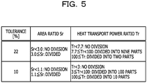
- the division method acquisition unit 32 performs thermal analysis on sample data (component data of sample product) by using the simple division method and the detailed division method and obtains an error between the analysis result and the actual measurement value. Then, the obtained error is associated with the division method, and a division method DB 44 as a second storage unit as illustrated in FIG. 5 is generated.
- the division method DB 44 includes a plurality of records (rows), and it is assumed that a division method associated with an error closest to a tolerance input by the user be used by the division number determination unit 20 described later.
- the user may determine how to use each division method in advance, for example, in a case where a tolerance is equal to or more than a predetermined value, the simple division method is used, and in a case where the tolerance is less than the predetermined value, the detailed division method is used.
- the component data acquisition unit 12 acquires component data of a target product of the thermal analysis input by the user of the thermal analysis device 10.
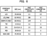
- the component data be data as illustrated in FIG. 6 .
- the component data is information regarding components included in the target product and includes each field of "component name", "size”, “heat conductivity”, and “heat consumption”.
- the name of the component is stored, and in the field of "size”, dimensions of the depth (D), the width (W), and the height (H) (unit [mm]) are stored.
- heat conductivity a value of the heat conductivity (unit [W/mK]) is stored, and in the field of "heat consumption", a value of the heat consumption (unit [W]) is stored.
- the estimation model generation and output unit 14 refers to the contact determination model DB 42 and estimates whether or not the components included in the component data acquired by the component data acquisition unit 12 have contact with each other. Furthermore, the estimation model generation and output unit 14 generates an estimation model table as illustrated in FIG. 7A as an estimation result and displays the generated table on the display unit 93.
- the estimation model table includes fields of "component name 1" and "component name 2" that are names of the respective components included in the component pair and a field of "contact” indicating whether or not the component pair has contact with each other. Note that the user refers to the estimation model table, and if there was information to be corrected, the user corrects the information.
- the estimation model table becomes a contact determination table as illustrated in FIG. 7B .
- a contact state between a component name 1 "LCD_Metal" and a component name 2 "graphite sheet" in the contact determination table in FIG. 7B is corrected by the user.
- the contact determination table acquisition unit 16 acquires the estimation model table confirmed by the user (that is, contact determination table in FIG. 7B ) and transmits the acquired contact determination table to the division number determination unit 20 and the thermal network model analysis unit 22.
- the tolerance acquisition unit 18 prompts the user to input a tolerance (that is, required accuracy), acquires a value of the input tolerance, and transmits the value to the division number determination unit 20.
- the division number determination unit 20 determines the division number of the thermal network model based on the division method DB 44 ( FIG. 5 ) by using the tolerance acquired by the tolerance acquisition unit 18 and the data of the contact determination table acquired by the contact determination table acquisition unit 16. The division number determination unit 20 transmits information regarding the determined division number to the thermal network model analysis unit 22.
- the thermal network model analysis unit 22 constructs a thermal network model by using the division number determined by the division number determination unit 20 and the information regarding the contact determination table and performs thermal analysis. Note that at the time of thermal analysis, the component data acquired by the component data acquisition unit 12 and the like are also used.
- the learning unit 24 calculates an error between the analysis result and the actual measurement value.
- a network analysis result, an actual measurement value, and an error regarding a rising temperature of a display are illustrated as an example.
- an error P can be calculated by the following formula (4).
- P % ⁇ T 1 ⁇ ⁇ T 2 / ⁇ T 1 ⁇ 100
- the learning unit 24 updates the division method DB 44 by using the calculated error and the division method and adds the information regarding the contact determination table used for the thermal analysis to the design asset DB 40.
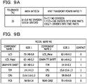
- the learning unit 24 adds the data in FIG. 9A to the division method DB 44 and adds the model data illustrated in FIG. 9B to the design asset DB 40.
- the model data in FIG. 9B is a collection of component names and sizes of the component pairs included in the product on which the thermal analysis has been performed, and whether the component pair has contact with each other.
- the contact determination model generation unit 30 may newly generate a contact determination model each time when new data is added to the design asset DB 40 and may generate only a contact determination model designated by the user. Note that in a case where the calculated error deviates from the tolerance input by the user, the learning unit 24 may appropriately correct the contact determination model DB 42 and the division method DB 44.
- the contact determination model DB 42 stores the contact determination model generated by the contact determination model generation unit 30, and the data in FIG. 5 is generated by the division method acquisition unit 32 and stored in the division method DB 44.
- the component data acquisition unit 12 waits for an input of the component data in step S10.
- the component data acquisition unit 12 proceeds the procedure to step S12 and acquires the input component data ( FIG. 6 ).
- step S14 the tolerance acquisition unit 18 requests the user to input the tolerance via the display unit 93. Specifically, the tolerance acquisition unit 18 prompts the user to input the tolerance, for example, by displaying a tolerance input screen on the display unit 93.
- step S16 the tolerance acquisition unit 18 waits for an input of the tolerance.
- the tolerance acquisition unit 18 proceeds the procedure to step S18 and acquires the input tolerance.
- step S20 the estimation model generation and output unit 14 generates the estimation model table ( FIG. 7A ) from the component data with reference to the contact determination model DB 42.
- step S22 the estimation model generation and output unit 14 displays the estimation model table generated in step S20 on the display unit 93.
- step S24 the contact determination table acquisition unit 16 waits for the confirmation operation by the user.
- the contact determination table acquisition unit 16 proceeds the procedure to step S26 and acquires the estimation model table that has been changed and confirmed (that is, contact determination table).
- step S28 the division number determination unit 20 determines the division number for each component pair based on the tolerance with reference to the division method DB 44.
- step S30 the thermal network model analysis unit 22 constructs the thermal network model based on the division number determined in step S28, the contact determination table, the component data, and the like, executes thermal analysis processing, and outputs a thermal analysis result (display on display unit 93).
- step S30 As described above, at the time when the processing to step S30 is completed, all the processing in FIG. 10 is terminated.
- the thermal analysis can be performed in a short time. Note that it is assumed that the learning unit 24 appropriately execute the processing described above at a timing when the actual measurement value and the simulation result are acquired.
- FIG. 11 it is assumed to perform thermal analysis on a temperature of an Integrated Circuit (IC) in a case where a heat conductivity of a graphite sheet provided on a display side of the IC and a heat conductivity of a rear case are changed at the time of design of a mobile terminal.
- the thermal analysis result in this case is illustrated in FIG. 11 .
- the result as illustrated in FIG. 11 can be obtained in a short time. From this result, it is found that an effect in IC temperature reduction is more enhanced by increasing the heat conductivity of the rear case than by increasing the heat conductivity of the graphite sheet. Therefore, a designer can design based on this result.
- a workload to obtain the result in FIG. 11 can be reduced to about 1/3 than a case where a heat dissipation path to be reflected in thermal design is found as referring to Computer Aided Design (CAD) data to construct a model or a person sets the number of nodes per component as referring to experimental data and design asset (comparative example).
- CAD Computer Aided Design
- the estimation model generation and output unit 14 refers to the contact determination model DB 42 that stores the contact determination model obtained from the design asset in the past, estimates whether or not the component pair included in the target product has contact with each other, and generates the estimation model table (S20). Furthermore, the division number determination unit 20 refers to the division method DB 44 that stores a relationship between the parameters (Sr and Tr) regarding the thermal transfer of the two components and the division number of the thermal network model and determines the division number of the thermal network model of the component pair included in the target product (S28).
- the thermal network model analysis unit 22 constructs the thermal network model of the target product by using the contact determination table obtained by correcting the estimation model table and the division number determined by the division number determination unit 20 and performs thermal analysis (S30).
- the contact determination table can be easily created, and the division number can be automatically determined. Therefore, the construction of the thermal network model and the thermal analysis can be performed in a short time. Accordingly, since a large number of product configurations can be examined in an upstream process in the product design, the design can be easily made. Furthermore, even when thermal analysis is performed on a system in which components and sizes are mixed, the thermal analysis can be efficiently performed by using the contact determination model.
- the thermal network model is constructed by using the table (contact determination table) confirmed after the estimation model table generated by the estimation model generation and output unit 14 is output and confirmed and corrected by the user. With this operation, it is possible to perform thermal analysis after reflecting a design guide of the user.
- the tolerance acquisition unit 18 receives the input of the tolerance in the thermal analysis and determines the division number by the division method corresponding to the tolerance. Therefore, the appropriate division number can be determined with accuracy required by the user.
- the design asset DB 40 and the division method DB 44 are updated (learned) based on the thermal analysis result. Therefore, determination accuracy regarding whether or not the components have contact with each other and determination accuracy of the division number can be increased.
- the thermal analysis processing of the product such as the mobile terminal has been described.
- the present invention is not limited to this.
- the method similar to that in the embodiment can be adopted.
- the division number of a certain layer (for example, lower layer fine wiring portion) and the division number of another layer (for example, transistor) may be determined by different division methods.
- the area ratio and the heat transport power ratio are used.
- the present invention is not limited to this, and only one of the area ratio and the heat transport power ratio may be used.
- a parameter other than the area ratio and the heat transport power ratio may be adopted.
- the division number determination unit 20 determines the division number based on the tolerance.
- the present invention is not limited to this.
- the division number determination unit 20 may determine the division number without using the tolerance. In this case, it is sufficient that only one type of division method be prepared.
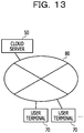
- a cloud server 50 connected to a network 80 such as the Internet as illustrated in FIG. 13 may has each function in FIG. 2 .
- the cloud server 50 receives component data, a tolerance, and the like input from a user terminal 70 and executes the processing in FIG. 10 .
- the cloud server 50 may be provided anywhere in Japan and overseas.
- processing functions described above can be implemented by a computer.
- a program is provided in which processing content of a function to be included in a processing apparatus is written.
- the above processing functions are implemented on the computer by executing the program by the computer.
- the program in which the processing content is written can be recorded in a computer-readable reading medium (except for a carrier wave).
- the program is sold in the form of a portable reading medium such as a digital versatile disc (DVD) or a compact disc read only memory (CD-ROM) in which the program is recorded.
- DVD digital versatile disc
- CD-ROM compact disc read only memory
- the computer which executes the program stores, for example, the program recorded in the portable reading medium or the program transferred from the server computer in a storage device of the computer. Then, the computer reads the program from the storage device of the computer and executes processing according to the program. Note that the computer can directly read the program from the portable reading medium and execute processing according to the program. Furthermore, the computer also can sequentially execute processing according to the received program each time when the program is transferred from the server computer.
Landscapes
- Engineering & Computer Science (AREA)
- Physics & Mathematics (AREA)
- Theoretical Computer Science (AREA)
- Computer Hardware Design (AREA)
- Evolutionary Computation (AREA)
- Geometry (AREA)
- General Engineering & Computer Science (AREA)
- General Physics & Mathematics (AREA)
- Investigating Or Analyzing Materials Using Thermal Means (AREA)
Abstract
Description
- The present invention relates to a thermal analysis device, a thermal analysis method, and a thermal analysis program.
- Conventionally, in thermal analysis on a printed circuit board on which a heating component is mounted, a specialist or the like has created a model and performed thermal analysis according to an analysis purpose and analysis accuracy in each case. However, to create the model, rich knowledge and the like are required, and thermal analysis cannot be quickly performed. Therefore, in recent years, a technology for automatically constructing a model has been studied (for example, refer to
Patent Documents 1 to 3, and the like). -
- Patent Document 1: Japanese Laid-open Patent Publication No.
2004-318250 - Patent Document 2: Japanese Laid-open Patent Publication No.
2007-122506 - Patent Document 3: Japanese Laid-open Patent Publication No.
2012-64036 - If thermal analysis can be performed in an upstream process in product design, a design guide can be easily made. To easily make the design guide, it is necessary to perform thermal analysis in a short time.
- In one aspect, an object of the present invention is to provide a thermal analysis device, a thermal analysis method, and a thermal analysis program capable of shortening time required for thermal analysis.
- In one aspect, a thermal analysis device includes an estimation unit that refers to a first storage unit that stores information regarding whether or not two components have contact with each other obtained from design information of a product in the past and estimates whether or not a component pair included in a target product has contact with each other, a determination unit that refers to a second storage unit that stores a relationship between a parameter regarding thermal transfer of the two components and the division number of a thermal network model and determines the division number of the thermal network model of the component pair included in the target product, and a thermal analysis unit that constructs the thermal network model of the target product by using an estimation result of the estimation unit and a determination result of the determination unit and performs thermal analysis.
- Time required for thermal analysis can be shortened.
-
-
FIG. 1 is a schematic diagram of a hardware configuration of a thermal analysis device according to one embodiment. -
FIG. 2 is a functional block diagram of the thermal analysis device. -
FIG. 3 is a diagram of data of each component pair. -
FIGs. 4A to 4C are diagrams for explaining a division method. -
FIG. 5 is a diagram of an exemplary data structure of a division method DB. -
FIG. 6 is a diagram of exemplary component data. -
FIG. 7A is a diagram of an estimation model table, andFIG. 7B is a diagram of a contact determination table. -
FIG. 8 is a table indicating a network analysis result, an actual measurement value, and an error regarding a rising temperature of a display. -
FIG. 9A is a diagram of exemplary data of a division method that is added to the division method DB by a learning unit, andFIG. 9B is a diagram of exemplary model data that is added to a design asset DB by the learning unit. -
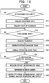
FIG. 10 is a flowchart of processing of the thermal analysis device. -
FIG. 11 is a diagram for explaining a method for utilizing thermal analysis. -
FIG. 12 is a diagram for explaining a modification. -
FIG. 13 is a diagram of an example in which a cloud server has a function of the thermal analysis device. - Hereinafter, one embodiment of a thermal analysis device will be described in detail with reference to
FIGs. 1 to 11 . - In
FIG. 1 , a hardware configuration of athermal analysis device 10 is illustrated. Thethermal analysis device 10 is a Personal Computer (PC) and the like, and as illustrated inFIG. 1 , thethermal analysis device 10 includes a Central Processing Unit (CPU) 90, a Read Only Memory (ROM) 92, a Random Access Memory (RAM) 94, a storage unit (here, Hard Disk Drive (HDD)) 96, anetwork interface 97, adisplay unit 93, aninput unit 95, a portablestorage medium drive 99, and the like. Each component of thethermal analysis device 10 is connected to abus 98. Thedisplay unit 93 includes a liquid crystal display and the like, and theinput unit 95 includes a keyboard, a mouse, a touch panel, and the like. In thethermal analysis device 10, theCPU 90 executes a program (including thermal analysis program) stored in theROM 92 or theHDD 96 or a program (including thermal analysis program) read from aportable storage medium 91 by the portablestorage medium drive 99 so as to implement the function of each unit illustrated inFIG. 2 . Note that inFIG. 2 , databases (DB) stored in theHDD 96 of thethermal analysis device 10 and the like are illustrated. - In the
thermal analysis device 10, theCPU 90 executes the program so as to implement functions of a contact determinationmodel generation unit 30, a divisionmethod acquisition unit 32, a componentdata acquisition unit 12, an estimation model generation andoutput unit 14 as an estimation unit, a contact determinationtable acquisition unit 16, atolerance acquisition unit 18 as a reception unit, a divisionnumber determination unit 20 as a determination unit, a thermal networkmodel analysis unit 22 as a thermal analysis unit, and alearning unit 24 as an update unit illustrated inFIG. 2 . - The contact determination
model generation unit 30 acquires information regarding a past product stored in adesign asset DB 40 and generates data of each component pair (FIG. 3 ) based on the acquired information. Here, the design asset DB 40 is a database that stores data similar to model data to be described later (refer toFIG. 9B ). Furthermore, the data of each component pair includes data of two components having contact with each other or facing each other in a product. Specifically, the data of each component pair includes data of "component name 1" and "component name 2" that are names of the two components included in the component pair, data of "size 1" and "size 2" that are sizes of the respective components, data of "network model" that is a name of a network model used for thermal analysis, and data of "contact" indicating whether or not the component pair has contact with each other. In the data of "contact", a value in a case where the component pair has contact with each other is "1", and a value in a case where the component pair does not have contact with each other is "0". - Furthermore, as illustrated in
FIG. 3 , the contact determinationmodel generation unit 30 performs logistic regression on the data of each component pair and generates a contact determination model. The contact determination model is a model used to determine whether or not the two components (component pair) included in the product have contact with each other (for example, model used to calculate probability of contact). The contact determinationmodel generation unit 30 stores the generated contact determination model in a contact determination model DB 42 as a first storage unit. Note that it can be said that the contact determination model is information regarding whether or not the two components have contact with each other obtained from product design information in the past. - The division
method acquisition unit 32 acquires information regarding a division method based on a thermal network model which has been used in thermal analysis in the past, created by a user. - As an example, it is assumed that the division method according to the present embodiment be a method for determining the number of divisions by using an area ratio of the two components and a heat transport power ratio of the two components as parameters.
FIGs. 4A to 4C are diagrams for explaining the division method. As illustrated inFIG. 4A , in a case where the component pair includes acomponent 1 and acomponent 2, an area ratio Sr and a heat transport power ratio Tr are respectively expressed as the following formulas (1) and (2).

- Note that the heat transport power [W/K] is expressed as the following formula (3).

- Then, the user divides the division methods into a simple division method (division method with large tolerance) and a detailed division method (division method with small tolerance) and determines a division method based on the thermal network model that has been used in the thermal analysis in the past.
- For example, in the example in
FIG. 4B , when a simple division method is used, in a case of Sr < 3.0, no division is made, and in a case of 3.0 ≤ Sr, division is made. Furthermore, if Tr < 7.7, no division is made, in a case of 7.7 ≤ Tr < 100, division into nine parts is made, and in a case of 100 ≤ Tr, division into two parts is made. On the other hand, when a detailed division method is used, as illustrated inFIG. 4C , in a case of Sr < 1.1, no division is made, and in a case of 1.1 ≤ Sr, division is made. Furthermore, if Tr < 3, no division is made, in a case of 3 ≤ Tr < 100, division into 100 parts is made, and in a case of 100 ≤ Tr, division into 10 parts is made. - Then, the division
method acquisition unit 32 performs thermal analysis on sample data (component data of sample product) by using the simple division method and the detailed division method and obtains an error between the analysis result and the actual measurement value. Then, the obtained error is associated with the division method, and adivision method DB 44 as a second storage unit as illustrated inFIG. 5 is generated. Note that thedivision method DB 44 includes a plurality of records (rows), and it is assumed that a division method associated with an error closest to a tolerance input by the user be used by the divisionnumber determination unit 20 described later. Note that the user may determine how to use each division method in advance, for example, in a case where a tolerance is equal to or more than a predetermined value, the simple division method is used, and in a case where the tolerance is less than the predetermined value, the detailed division method is used. - Returning to
FIG. 2 , the componentdata acquisition unit 12 acquires component data of a target product of the thermal analysis input by the user of thethermal analysis device 10. Here, as an example, it is assumed that the component data be data as illustrated inFIG. 6 . Specifically, the component data is information regarding components included in the target product and includes each field of "component name", "size", "heat conductivity", and "heat consumption". In the field of "component name", the name of the component is stored, and in the field of "size", dimensions of the depth (D), the width (W), and the height (H) (unit [mm]) are stored. Furthermore, in the field of "heat conductivity", a value of the heat conductivity (unit [W/mK]) is stored, and in the field of "heat consumption", a value of the heat consumption (unit [W]) is stored. - The estimation model generation and
output unit 14 refers to the contactdetermination model DB 42 and estimates whether or not the components included in the component data acquired by the componentdata acquisition unit 12 have contact with each other. Furthermore, the estimation model generation andoutput unit 14 generates an estimation model table as illustrated inFIG. 7A as an estimation result and displays the generated table on thedisplay unit 93. Here, the estimation model table includes fields of "component name 1" and "component name 2" that are names of the respective components included in the component pair and a field of "contact" indicating whether or not the component pair has contact with each other. Note that the user refers to the estimation model table, and if there was information to be corrected, the user corrects the information. Then, when the correction is completed, the user performs a confirmation operation (for example, to push confirmation button, and the like). In a case where the user performs the confirmation operation, the estimation model table becomes a contact determination table as illustrated inFIG. 7B . Note that as understood from the comparison withFIG. 7A , a contact state between acomponent name 1 "LCD_Metal" and acomponent name 2 "graphite sheet" in the contact determination table inFIG. 7B is corrected by the user. - Returning to
FIG. 2 , the contact determinationtable acquisition unit 16 acquires the estimation model table confirmed by the user (that is, contact determination table inFIG. 7B ) and transmits the acquired contact determination table to the divisionnumber determination unit 20 and the thermal networkmodel analysis unit 22. - The
tolerance acquisition unit 18 prompts the user to input a tolerance (that is, required accuracy), acquires a value of the input tolerance, and transmits the value to the divisionnumber determination unit 20. - The division
number determination unit 20 determines the division number of the thermal network model based on the division method DB 44 (FIG. 5 ) by using the tolerance acquired by thetolerance acquisition unit 18 and the data of the contact determination table acquired by the contact determinationtable acquisition unit 16. The divisionnumber determination unit 20 transmits information regarding the determined division number to the thermal networkmodel analysis unit 22. - The thermal network
model analysis unit 22 constructs a thermal network model by using the division number determined by the divisionnumber determination unit 20 and the information regarding the contact determination table and performs thermal analysis. Note that at the time of thermal analysis, the component data acquired by the componentdata acquisition unit 12 and the like are also used. - When acquiring an analysis result by the thermal network
model analysis unit 22 and acquiring the actual measurement value and a simulation result (hereinafter, simply referred to as "actual measurement value"), thelearning unit 24 calculates an error between the analysis result and the actual measurement value. InFIG. 8 , a network analysis result, an actual measurement value, and an error regarding a rising temperature of a display are illustrated as an example. When it is assumed that the network analysis result of the rising temperature be ΔT1 and the actual measurement value of the rising temperature be ΔT2, an error P can be calculated by the following formula (4).
- Then, the
learning unit 24 updates thedivision method DB 44 by using the calculated error and the division method and adds the information regarding the contact determination table used for the thermal analysis to thedesign asset DB 40. For example, thelearning unit 24 adds the data inFIG. 9A to thedivision method DB 44 and adds the model data illustrated inFIG. 9B to thedesign asset DB 40. Note that the model data inFIG. 9B is a collection of component names and sizes of the component pairs included in the product on which the thermal analysis has been performed, and whether the component pair has contact with each other. Note that the contact determinationmodel generation unit 30 may newly generate a contact determination model each time when new data is added to thedesign asset DB 40 and may generate only a contact determination model designated by the user. Note that in a case where the calculated error deviates from the tolerance input by the user, thelearning unit 24 may appropriately correct the contactdetermination model DB 42 and thedivision method DB 44. - Next, processing by the
thermal analysis device 10 will be described with reference to the flowchart inFIG. 10 . Note that at the time when the processing inFIG. 10 is executed, the contactdetermination model DB 42 stores the contact determination model generated by the contact determinationmodel generation unit 30, and the data inFIG. 5 is generated by the divisionmethod acquisition unit 32 and stored in thedivision method DB 44. - When the processing in
FIG. 10 is started, the componentdata acquisition unit 12 waits for an input of the component data in step S10. When the component data is input, the componentdata acquisition unit 12 proceeds the procedure to step S12 and acquires the input component data (FIG. 6 ). - Next, in step S14, the
tolerance acquisition unit 18 requests the user to input the tolerance via thedisplay unit 93. Specifically, thetolerance acquisition unit 18 prompts the user to input the tolerance, for example, by displaying a tolerance input screen on thedisplay unit 93. - Next, in step S16, the
tolerance acquisition unit 18 waits for an input of the tolerance. When the user inputs the tolerance via theinput unit 95, thetolerance acquisition unit 18 proceeds the procedure to step S18 and acquires the input tolerance. - Next, in step S20, the estimation model generation and
output unit 14 generates the estimation model table (FIG. 7A ) from the component data with reference to the contactdetermination model DB 42. Next, in step S22, the estimation model generation andoutput unit 14 displays the estimation model table generated in step S20 on thedisplay unit 93. - Next, in step S24, the contact determination
table acquisition unit 16 waits for the confirmation operation by the user. When the user performs the confirmation operation, the contact determinationtable acquisition unit 16 proceeds the procedure to step S26 and acquires the estimation model table that has been changed and confirmed (that is, contact determination table). - Next, in step S28, the division
number determination unit 20 determines the division number for each component pair based on the tolerance with reference to thedivision method DB 44. - Next, in step S30, the thermal network
model analysis unit 22 constructs the thermal network model based on the division number determined in step S28, the contact determination table, the component data, and the like, executes thermal analysis processing, and outputs a thermal analysis result (display on display unit 93). - As described above, at the time when the processing to step S30 is completed, all the processing in
FIG. 10 is terminated. In the present embodiment, by executing the processing inFIG. 10 , even if the user is not a trained expert, the thermal analysis can be performed in a short time. Note that it is assumed that thelearning unit 24 appropriately execute the processing described above at a timing when the actual measurement value and the simulation result are acquired. - Here, for example, it is assumed to perform thermal analysis on a temperature of an Integrated Circuit (IC) in a case where a heat conductivity of a graphite sheet provided on a display side of the IC and a heat conductivity of a rear case are changed at the time of design of a mobile terminal. The thermal analysis result in this case is illustrated in
FIG. 11 . In the present embodiment, by executing the processing along the flowchart inFIG. 10 at the time of thermal analysis, the result as illustrated inFIG. 11 can be obtained in a short time. From this result, it is found that an effect in IC temperature reduction is more enhanced by increasing the heat conductivity of the rear case than by increasing the heat conductivity of the graphite sheet. Therefore, a designer can design based on this result. Note that a workload to obtain the result inFIG. 11 can be reduced to about 1/3 than a case where a heat dissipation path to be reflected in thermal design is found as referring to Computer Aided Design (CAD) data to construct a model or a person sets the number of nodes per component as referring to experimental data and design asset (comparative example). - As described above in detail, according to the present embodiment, the estimation model generation and
output unit 14 refers to the contactdetermination model DB 42 that stores the contact determination model obtained from the design asset in the past, estimates whether or not the component pair included in the target product has contact with each other, and generates the estimation model table (S20). Furthermore, the divisionnumber determination unit 20 refers to thedivision method DB 44 that stores a relationship between the parameters (Sr and Tr) regarding the thermal transfer of the two components and the division number of the thermal network model and determines the division number of the thermal network model of the component pair included in the target product (S28). Then, the thermal networkmodel analysis unit 22 constructs the thermal network model of the target product by using the contact determination table obtained by correcting the estimation model table and the division number determined by the divisionnumber determination unit 20 and performs thermal analysis (S30). With this operation, in the present embodiment, even if the user is not a skilled designer and the like, the contact determination table can be easily created, and the division number can be automatically determined. Therefore, the construction of the thermal network model and the thermal analysis can be performed in a short time. Accordingly, since a large number of product configurations can be examined in an upstream process in the product design, the design can be easily made. Furthermore, even when thermal analysis is performed on a system in which components and sizes are mixed, the thermal analysis can be efficiently performed by using the contact determination model. - Furthermore, in the present embodiment, the thermal network model is constructed by using the table (contact determination table) confirmed after the estimation model table generated by the estimation model generation and
output unit 14 is output and confirmed and corrected by the user. With this operation, it is possible to perform thermal analysis after reflecting a design guide of the user. - Furthermore, in the present embodiment, the
tolerance acquisition unit 18 receives the input of the tolerance in the thermal analysis and determines the division number by the division method corresponding to the tolerance. Therefore, the appropriate division number can be determined with accuracy required by the user. - Furthermore, in the present embodiment, the
design asset DB 40 and thedivision method DB 44 are updated (learned) based on the thermal analysis result. Therefore, determination accuracy regarding whether or not the components have contact with each other and determination accuracy of the division number can be increased. - Note that in the embodiment, the thermal analysis processing of the product such as the mobile terminal has been described. However, the present invention is not limited to this. For example, when a model used to estimate a temperature of a part that is difficult to predict from an analysis result of a broken LSI is constructed, the method similar to that in the embodiment can be adopted. In this case, for example, as in a case of multilayer, in a case where a size and a material of an analysis target largely differ according to a layer, as illustrated in
FIG. 12 , the division number of a certain layer (for example, lower layer fine wiring portion) and the division number of another layer (for example, transistor) may be determined by different division methods. - Note that in the embodiment, as the parameters regarding the thermal transfer of the two components that are used when the division number is determined, the area ratio and the heat transport power ratio are used. However, the present invention is not limited to this, and only one of the area ratio and the heat transport power ratio may be used. Furthermore, as the parameters regarding the thermal transfer of the two components, a parameter other than the area ratio and the heat transport power ratio may be adopted.
- Note that in the embodiment, a case has been described in which the user is made to input the tolerance and the division
number determination unit 20 determines the division number based on the tolerance. However, the present invention is not limited to this. For example, the divisionnumber determination unit 20 may determine the division number without using the tolerance. In this case, it is sufficient that only one type of division method be prepared. - Note that in the embodiment, a case has been described in which the
thermal analysis device 10 has each function inFIG. 2 . However, the present invention is not limited to this. For example, acloud server 50 connected to anetwork 80 such as the Internet as illustrated inFIG. 13 may has each function inFIG. 2 . In this case, thecloud server 50 receives component data, a tolerance, and the like input from auser terminal 70 and executes the processing inFIG. 10 . Note that thecloud server 50 may be provided anywhere in Japan and overseas. - Note that the processing functions described above can be implemented by a computer. In that case, a program is provided in which processing content of a function to be included in a processing apparatus is written. The above processing functions are implemented on the computer by executing the program by the computer. The program in which the processing content is written can be recorded in a computer-readable reading medium (except for a carrier wave).
- In a case of distributing the program, for example, the program is sold in the form of a portable reading medium such as a digital versatile disc (DVD) or a compact disc read only memory (CD-ROM) in which the program is recorded. Alternatively, it is possible to store the program in a storage device of a server computer and transfer the program from the server computer to another computer via a network.
- The computer which executes the program stores, for example, the program recorded in the portable reading medium or the program transferred from the server computer in a storage device of the computer. Then, the computer reads the program from the storage device of the computer and executes processing according to the program. Note that the computer can directly read the program from the portable reading medium and execute processing according to the program. Furthermore, the computer also can sequentially execute processing according to the received program each time when the program is transferred from the server computer.
- The embodiment described above is a preferred example of carrying out the present invention. However, the present invention is not limited to this, and a variety of modifications can be made without departing from the scope of the present invention.
-
- 10: Thermal analysis device
- 14: Estimation model generation and output unit (estimation unit)
- 18: Tolerance acquisition unit (reception unit)
- 20: Division number determination unit (determination unit)
- 22: Thermal network model analysis unit (thermal analysis unit)
- 24: Learning unit (update unit)
- 42: Contact determination model DB (first storage unit)
- 44: Division method DB (second storage unit)
Claims (13)
- A thermal analysis device comprising:an estimation unit configured to refer to a first storage unit that stores information regarding whether or not two components have contact with each other obtained from design information of a product in the past and estimate whether or not a component pair included in a target product has contact with each other;a determination unit configured to refer to a second storage unit that stores a relationship between a parameter regarding thermal transfer of the two components and the division number of a thermal network model and determine the division number of the thermal network model of the component pair included in the target product; anda thermal analysis unit configured to construct the thermal network model of the target product by using an estimation result of the estimation unit and a determination result of the determination unit and perform thermal analysis.
- The thermal analysis device according to claim 1, wherein
the thermal analysis unit receives an input of a correction request of the estimation result of the estimation unit and constructs the thermal network model of the target product by using the estimation result reflecting the correction request. - The thermal analysis device according to claim 1 or 2, further comprising:a reception unit configured to receive an input of required accuracy for the thermal analysis, whereinthe second storage unit stores the relationship between the parameter regarding the thermal transfer of the two components and the division number of the thermal network model in association with different required accuracy, andthe determination unit determines the division number of the thermal network model of the component pair included in the target product by using the relationship between the parameter and the division number associated with the required accuracy received by the reception unit.
- The thermal analysis device according to any one of claims 1 to 3, wherein
the parameter regarding the thermal transfer includes an area ratio of the two components. - The thermal analysis device according to any one of claims 1 to 4, wherein
the parameter regarding the thermal transfer includes a ratio of ease of thermal transfer in the two components. - The thermal analysis device according to any one of claims 1 to 5, further comprising:
an update unit configured to update the first storage unit by using the estimation result of the estimation unit and update the second storage unit by using the determination result of the determination unit based on a thermal analysis result of the thermal analysis unit. - A thermal analysis method for causing a computer to execute processing for:referring to a first storage unit that stores information regarding whether or not two components have contact with each other obtained from design information of a product in the past and estimating whether or not a component pair included in a target product has contact with each other;referring to a second storage unit that stores a relationship between a parameter regarding thermal transfer of the two components and the division number of a thermal network model and determining the division number of the thermal network model of the component pair included in the target product; andconstructing the thermal network model of the target product by using an estimation result of the estimating processing and a determination result of the determining processing and performing thermal analysis.
- The thermal analysis method according to claim 7, wherein
in the processing for performing thermal analysis, an input of a correction request regarding the estimation result of the estimating processing is received, and the thermal network model of the target product is constructed by using the estimation result reflecting the correction request. - The thermal analysis method according to claim 7 or 8, causing the computer to further execute processing for:receiving an input of required accuracy for the thermal analysis, whereinthe second storage unit stores the relationship between the parameter regarding the thermal transfer of the two components and the division number of the thermal network model in association with different required accuracy, andin the determining processing, the division number of the thermal network model of the component pair included in the target product is determined by using the relationship between the parameter and the division number associated with the required accuracy received in the receiving processing.
- The thermal analysis method according to any one of claims 7 to 9, wherein
the parameter regarding the thermal transfer includes an area ratio of the two components. - The thermal analysis method according to any one of claims 7 to 10, wherein
the parameter regarding the thermal transfer includes a ratio of ease of thermal transfer in the two components. - The thermal analysis method according to any one of claims 7 to 11, wherein
the computer further executes processing for updating the first storage unit by using an estimation result of the estimating processing and updating the second storage unit by using a determination result of the determining processing based on a thermal analysis result of the processing for performing the thermal analysis. - A thermal analysis program for causing a computer to execute processing for:referring to a first storage unit that stores information regarding whether or not two components have contact with each other obtained from design information of a product in the past and estimating whether or not a component pair included in a target product has contact with each other;referring to a second storage unit that stores a relationship between a parameter regarding thermal transfer of the two components and the division number of a thermal network model and determining the division number of the thermal network model of the component pair included in the target product; andconstructing the thermal network model of the target product by using an estimation result of the estimating processing and a determination result of the determining processing and performing thermal analysis.
Applications Claiming Priority (1)
| Application Number | Priority Date | Filing Date | Title |
|---|---|---|---|
| PCT/JP2017/021459 WO2018225243A1 (en) | 2017-06-09 | 2017-06-09 | Thermal analysis device, thermal analysis method, and thermal analysis program |
Publications (2)
| Publication Number | Publication Date |
|---|---|
| EP3637286A1 true EP3637286A1 (en) | 2020-04-15 |
| EP3637286A4 EP3637286A4 (en) | 2020-06-17 |
Family
ID=64566641
Family Applications (1)
| Application Number | Title | Priority Date | Filing Date |
|---|---|---|---|
| EP17912529.9A Withdrawn EP3637286A4 (en) | 2017-06-09 | 2017-06-09 | THERMAL ANALYSIS DEVICE, THERMAL ANALYSIS METHOD AND THERMAL ANALYSIS PROGRAM |
Country Status (5)
| Country | Link |
|---|---|
| US (1) | US20200074026A1 (en) |
| EP (1) | EP3637286A4 (en) |
| JP (1) | JP6753528B2 (en) |
| CN (1) | CN110709849A (en) |
| WO (1) | WO2018225243A1 (en) |
Family Cites Families (14)
| Publication number | Priority date | Publication date | Assignee | Title |
|---|---|---|---|---|
| US5202843A (en) * | 1990-04-25 | 1993-04-13 | Oki Electric Industry Co., Ltd. | CAE system for automatic heat analysis of electronic equipment |
| JP2002183223A (en) * | 2000-12-15 | 2002-06-28 | Sharp Corp | Mesh processing device, mesh processing method, and computer-readable recording medium storing mesh processing program |
| JP2002230047A (en) * | 2001-02-02 | 2002-08-16 | Nec Corp | System, method and recording medium for generating thermal network data |
| JP2003011199A (en) * | 2001-07-04 | 2003-01-15 | Canon Inc | Injection molding process simulation apparatus and shape accuracy prediction method |
| JP4097176B2 (en) * | 2001-08-02 | 2008-06-11 | 本田技研工業株式会社 | Thermal analysis method and apparatus |
| JP4213500B2 (en) * | 2003-04-11 | 2009-01-21 | 富士通株式会社 | Thermal analysis modeling method and thermal analysis modeling program |
| JP2007122506A (en) * | 2005-10-28 | 2007-05-17 | Fujitsu Ltd | Thermal fluid analysis model generation program, thermal fluid analysis model generation device, and thermal fluid analysis model generation method |
| JP2007293382A (en) * | 2006-04-20 | 2007-11-08 | Sony Corp | Thermal analysis apparatus, thermal analysis method, and thermal analysis processing program |
| JP2008082901A (en) * | 2006-09-27 | 2008-04-10 | Sharp Corp | Thermal analysis method, thermal analysis apparatus, and thermal analysis program |
| JP2009026085A (en) * | 2007-07-19 | 2009-02-05 | Sharp Corp | Thermal analysis apparatus, thermal analysis method, program, and recording medium |
| JP2009129196A (en) * | 2007-11-22 | 2009-06-11 | Sharp Corp | Thermal analysis model generation apparatus, thermal analysis model generation method, thermal analysis apparatus, and thermal analysis method |
| US8103996B2 (en) * | 2008-06-24 | 2012-01-24 | Cadence Design Systems, Inc. | Method and apparatus for thermal analysis of through-silicon via (TSV) |
| JP5541032B2 (en) | 2010-09-16 | 2014-07-09 | 富士通株式会社 | Thermal analysis model generation apparatus, thermal analysis model generation program, thermal analysis model generation method, and thermal analysis apparatus |
| JP6544965B2 (en) * | 2015-03-31 | 2019-07-17 | キヤノン株式会社 | INFORMATION PROCESSING APPARATUS, INFORMATION PROCESSING METHOD, AND PROGRAM |
-
2017
- 2017-06-09 WO PCT/JP2017/021459 patent/WO2018225243A1/en not_active Ceased
- 2017-06-09 CN CN201780091202.3A patent/CN110709849A/en active Pending
- 2017-06-09 EP EP17912529.9A patent/EP3637286A4/en not_active Withdrawn
- 2017-06-09 JP JP2019523311A patent/JP6753528B2/en not_active Expired - Fee Related
-
2019
- 2019-11-11 US US16/679,372 patent/US20200074026A1/en not_active Abandoned
Also Published As
| Publication number | Publication date |
|---|---|
| JP6753528B2 (en) | 2020-09-09 |
| US20200074026A1 (en) | 2020-03-05 |
| EP3637286A4 (en) | 2020-06-17 |
| WO2018225243A1 (en) | 2018-12-13 |
| JPWO2018225243A1 (en) | 2019-12-12 |
| CN110709849A (en) | 2020-01-17 |
Similar Documents
| Publication | Publication Date | Title |
|---|---|---|
| Ruscio et al. | Simulating multivariate nonnormal data using an iterative algorithm | |
| Yan et al. | Model selection for Cox models with time-varying coefficients | |
| JP6493006B2 (en) | Population estimation method, population estimation program, and population estimation device | |
| Wang et al. | Bayesian quantile structural equation models | |
| Pan et al. | Multiple-steps step-stress accelerated degradation modeling based on Wiener and gamma processes | |
| Lu et al. | A partially linear proportional hazards model for current status data | |
| CN118865268A (en) | Intelligent control system and method for material mixer | |
| WO2017000743A1 (en) | Method and device for software recommendation | |
| CN111026849A (en) | Data processing method and device | |
| Amatya et al. | PoisNor: An R package for generation of multivariate data with Poisson and normal marginals | |
| US20130212100A1 (en) | Estimating rate of change of documents | |
| Chen et al. | Wald tests for variance-adjusted equivalence assessment with normal endpoints | |
| EP3637286A1 (en) | Thermal analysis device, thermal analysis method, and thermal analysis program | |
| Pritikin | A comparison of parameter covariance estimation methods for item response models in an expectation-maximization framework | |
| Harrison et al. | Power calculation for analyses of cross‐sectional stepped‐wedge cluster randomized trials with binary outcomes via generalized estimating equations | |
| US10380157B2 (en) | Ranking proximity of data sources with authoritative entities in social networks | |
| Gillard | A generalised Box–Cox transformation for the parametric estimation of clinical reference intervals | |
| Chen et al. | Lower confidence limits on the generalized exponential distribution percentiles under progressive type-I interval censoring | |
| Yan et al. | Generalized fiducial inference for the Lomax distribution | |
| Chen | Tests for the goodness-of-fit of the Laplace distribution | |
| US12475497B2 (en) | Method, system, and medium for generating recommendations utilizing an edge-computing-based asynchronous coagent network | |
| CN110764662A (en) | Information processing method, information processing device, electronic equipment and storage medium | |
| CN116522911A (en) | Entity alignment method and device | |
| Amiri et al. | An improvement of the nonparametric bootstrap test for the comparison of the coefficient of variations | |
| US20240135253A1 (en) | Computer-readable recording medium storing machine learning support program, machine learning support method, and information processing apparatus |
Legal Events
| Date | Code | Title | Description |
|---|---|---|---|
| STAA | Information on the status of an ep patent application or granted ep patent |
Free format text: STATUS: THE INTERNATIONAL PUBLICATION HAS BEEN MADE |
|
| PUAI | Public reference made under article 153(3) epc to a published international application that has entered the european phase |
Free format text: ORIGINAL CODE: 0009012 |
|
| STAA | Information on the status of an ep patent application or granted ep patent |
Free format text: STATUS: REQUEST FOR EXAMINATION WAS MADE |
|
| 17P | Request for examination filed |
Effective date: 20191031 |
|
| AK | Designated contracting states |
Kind code of ref document: A1 Designated state(s): AL AT BE BG CH CY CZ DE DK EE ES FI FR GB GR HR HU IE IS IT LI LT LU LV MC MK MT NL NO PL PT RO RS SE SI SK SM TR |
|
| AX | Request for extension of the european patent |
Extension state: BA ME |
|
| REG | Reference to a national code |
Ref country code: DE Ref legal event code: R079 Free format text: PREVIOUS MAIN CLASS: G06F0017500000 Ipc: G06F0030230000 |
|
| A4 | Supplementary search report drawn up and despatched |
Effective date: 20200515 |
|
| RIC1 | Information provided on ipc code assigned before grant |
Ipc: G06F 119/20 20200101ALN20200511BHEP Ipc: G06F 119/08 20200101ALN20200511BHEP Ipc: G06F 30/23 20200101AFI20200511BHEP |
|
| DAV | Request for validation of the european patent (deleted) | ||
| DAX | Request for extension of the european patent (deleted) | ||
| STAA | Information on the status of an ep patent application or granted ep patent |
Free format text: STATUS: EXAMINATION IS IN PROGRESS |
|
| 17Q | First examination report despatched |
Effective date: 20211014 |
|
| STAA | Information on the status of an ep patent application or granted ep patent |
Free format text: STATUS: THE APPLICATION IS DEEMED TO BE WITHDRAWN |
|
| 18D | Application deemed to be withdrawn |
Effective date: 20240103 |