EP3637111A1 - Air data probe repair - Google Patents
Air data probe repair Download PDFInfo
- Publication number
- EP3637111A1 EP3637111A1 EP19202541.9A EP19202541A EP3637111A1 EP 3637111 A1 EP3637111 A1 EP 3637111A1 EP 19202541 A EP19202541 A EP 19202541A EP 3637111 A1 EP3637111 A1 EP 3637111A1
- Authority
- EP
- European Patent Office
- Prior art keywords
- air data
- data probe
- port inlet
- probe
- recited
- Prior art date
- Legal status (The legal status is an assumption and is not a legal conclusion. Google has not performed a legal analysis and makes no representation as to the accuracy of the status listed.)
- Granted
Links
Images




Classifications
-
- G—PHYSICS
- G01—MEASURING; TESTING
- G01P—MEASURING LINEAR OR ANGULAR SPEED, ACCELERATION, DECELERATION, OR SHOCK; INDICATING PRESENCE, ABSENCE, OR DIRECTION, OF MOVEMENT
- G01P5/00—Measuring speed of fluids, e.g. of air stream; Measuring speed of bodies relative to fluids, e.g. of ship, of aircraft
- G01P5/14—Measuring speed of fluids, e.g. of air stream; Measuring speed of bodies relative to fluids, e.g. of ship, of aircraft by measuring differences of pressure in the fluid
- G01P5/16—Measuring speed of fluids, e.g. of air stream; Measuring speed of bodies relative to fluids, e.g. of ship, of aircraft by measuring differences of pressure in the fluid using Pitot tubes, e.g. Machmeter
- G01P5/165—Arrangements or constructions of Pitot tubes
-
- B—PERFORMING OPERATIONS; TRANSPORTING
- B22—CASTING; POWDER METALLURGY
- B22F—WORKING METALLIC POWDER; MANUFACTURE OF ARTICLES FROM METALLIC POWDER; MAKING METALLIC POWDER; APPARATUS OR DEVICES SPECIALLY ADAPTED FOR METALLIC POWDER
- B22F7/00—Manufacture of composite layers, workpieces, or articles, comprising metallic powder, by sintering the powder, with or without compacting wherein at least one part is obtained by sintering or compression
- B22F7/06—Manufacture of composite layers, workpieces, or articles, comprising metallic powder, by sintering the powder, with or without compacting wherein at least one part is obtained by sintering or compression of composite workpieces or articles from parts, e.g. to form tipped tools
- B22F7/062—Manufacture of composite layers, workpieces, or articles, comprising metallic powder, by sintering the powder, with or without compacting wherein at least one part is obtained by sintering or compression of composite workpieces or articles from parts, e.g. to form tipped tools involving the connection or repairing of preformed parts
-
- B—PERFORMING OPERATIONS; TRANSPORTING
- B64—AIRCRAFT; AVIATION; COSMONAUTICS
- B64D—EQUIPMENT FOR FITTING IN OR TO AIRCRAFT; FLIGHT SUITS; PARACHUTES; ARRANGEMENT OR MOUNTING OF POWER PLANTS OR PROPULSION TRANSMISSIONS IN AIRCRAFT
- B64D43/00—Arrangements or adaptations of instruments
- B64D43/02—Arrangements or adaptations of instruments for indicating aircraft speed or stalling conditions
-
- B—PERFORMING OPERATIONS; TRANSPORTING
- B64—AIRCRAFT; AVIATION; COSMONAUTICS
- B64F—GROUND OR AIRCRAFT-CARRIER-DECK INSTALLATIONS SPECIALLY ADAPTED FOR USE IN CONNECTION WITH AIRCRAFT; DESIGNING, MANUFACTURING, ASSEMBLING, CLEANING, MAINTAINING OR REPAIRING AIRCRAFT, NOT OTHERWISE PROVIDED FOR; HANDLING, TRANSPORTING, TESTING OR INSPECTING AIRCRAFT COMPONENTS, NOT OTHERWISE PROVIDED FOR
- B64F5/00—Designing, manufacturing, assembling, cleaning, maintaining or repairing aircraft, not otherwise provided for; Handling, transporting, testing or inspecting aircraft components, not otherwise provided for
- B64F5/40—Maintaining or repairing aircraft
-
- G—PHYSICS
- G01—MEASURING; TESTING
- G01P—MEASURING LINEAR OR ANGULAR SPEED, ACCELERATION, DECELERATION, OR SHOCK; INDICATING PRESENCE, ABSENCE, OR DIRECTION, OF MOVEMENT
- G01P13/00—Indicating or recording presence, absence, or direction, of movement
- G01P13/02—Indicating direction only, e.g. by weather vane
- G01P13/025—Indicating direction only, e.g. by weather vane indicating air data, i.e. flight variables of an aircraft, e.g. angle of attack, side slip, shear, yaw
-
- B—PERFORMING OPERATIONS; TRANSPORTING
- B22—CASTING; POWDER METALLURGY
- B22F—WORKING METALLIC POWDER; MANUFACTURE OF ARTICLES FROM METALLIC POWDER; MAKING METALLIC POWDER; APPARATUS OR DEVICES SPECIALLY ADAPTED FOR METALLIC POWDER
- B22F10/00—Additive manufacturing of workpieces or articles from metallic powder
- B22F10/20—Direct sintering or melting
- B22F10/25—Direct deposition of metal particles, e.g. direct metal deposition [DMD] or laser engineered net shaping [LENS]
-
- B—PERFORMING OPERATIONS; TRANSPORTING
- B22—CASTING; POWDER METALLURGY
- B22F—WORKING METALLIC POWDER; MANUFACTURE OF ARTICLES FROM METALLIC POWDER; MAKING METALLIC POWDER; APPARATUS OR DEVICES SPECIALLY ADAPTED FOR METALLIC POWDER
- B22F10/00—Additive manufacturing of workpieces or articles from metallic powder
- B22F10/20—Direct sintering or melting
- B22F10/28—Powder bed fusion, e.g. selective laser melting [SLM] or electron beam melting [EBM]
-
- B—PERFORMING OPERATIONS; TRANSPORTING
- B22—CASTING; POWDER METALLURGY
- B22F—WORKING METALLIC POWDER; MANUFACTURE OF ARTICLES FROM METALLIC POWDER; MAKING METALLIC POWDER; APPARATUS OR DEVICES SPECIALLY ADAPTED FOR METALLIC POWDER
- B22F7/00—Manufacture of composite layers, workpieces, or articles, comprising metallic powder, by sintering the powder, with or without compacting wherein at least one part is obtained by sintering or compression
- B22F7/06—Manufacture of composite layers, workpieces, or articles, comprising metallic powder, by sintering the powder, with or without compacting wherein at least one part is obtained by sintering or compression of composite workpieces or articles from parts, e.g. to form tipped tools
- B22F7/062—Manufacture of composite layers, workpieces, or articles, comprising metallic powder, by sintering the powder, with or without compacting wherein at least one part is obtained by sintering or compression of composite workpieces or articles from parts, e.g. to form tipped tools involving the connection or repairing of preformed parts
- B22F2007/068—Manufacture of composite layers, workpieces, or articles, comprising metallic powder, by sintering the powder, with or without compacting wherein at least one part is obtained by sintering or compression of composite workpieces or articles from parts, e.g. to form tipped tools involving the connection or repairing of preformed parts repairing articles
-
- B—PERFORMING OPERATIONS; TRANSPORTING
- B22—CASTING; POWDER METALLURGY
- B22F—WORKING METALLIC POWDER; MANUFACTURE OF ARTICLES FROM METALLIC POWDER; MAKING METALLIC POWDER; APPARATUS OR DEVICES SPECIALLY ADAPTED FOR METALLIC POWDER
- B22F2999/00—Aspects linked to processes or compositions used in powder metallurgy
-
- B—PERFORMING OPERATIONS; TRANSPORTING
- B33—ADDITIVE MANUFACTURING TECHNOLOGY
- B33Y—ADDITIVE MANUFACTURING, i.e. MANUFACTURING OF THREE-DIMENSIONAL [3D] OBJECTS BY ADDITIVE DEPOSITION, ADDITIVE AGGLOMERATION OR ADDITIVE LAYERING, e.g. BY 3D PRINTING, STEREOLITHOGRAPHY OR SELECTIVE LASER SINTERING
- B33Y10/00—Processes of additive manufacturing
-
- B—PERFORMING OPERATIONS; TRANSPORTING
- B33—ADDITIVE MANUFACTURING TECHNOLOGY
- B33Y—ADDITIVE MANUFACTURING, i.e. MANUFACTURING OF THREE-DIMENSIONAL [3D] OBJECTS BY ADDITIVE DEPOSITION, ADDITIVE AGGLOMERATION OR ADDITIVE LAYERING, e.g. BY 3D PRINTING, STEREOLITHOGRAPHY OR SELECTIVE LASER SINTERING
- B33Y80/00—Products made by additive manufacturing
-
- G—PHYSICS
- G01—MEASURING; TESTING
- G01P—MEASURING LINEAR OR ANGULAR SPEED, ACCELERATION, DECELERATION, OR SHOCK; INDICATING PRESENCE, ABSENCE, OR DIRECTION, OF MOVEMENT
- G01P21/00—Testing or calibrating of apparatus or devices covered by the preceding groups
- G01P21/02—Testing or calibrating of apparatus or devices covered by the preceding groups of speedometers
- G01P21/025—Testing or calibrating of apparatus or devices covered by the preceding groups of speedometers for measuring speed of fluids; for measuring speed of bodies relative to fluids
-
- Y—GENERAL TAGGING OF NEW TECHNOLOGICAL DEVELOPMENTS; GENERAL TAGGING OF CROSS-SECTIONAL TECHNOLOGIES SPANNING OVER SEVERAL SECTIONS OF THE IPC; TECHNICAL SUBJECTS COVERED BY FORMER USPC CROSS-REFERENCE ART COLLECTIONS [XRACs] AND DIGESTS
- Y02—TECHNOLOGIES OR APPLICATIONS FOR MITIGATION OR ADAPTATION AGAINST CLIMATE CHANGE
- Y02P—CLIMATE CHANGE MITIGATION TECHNOLOGIES IN THE PRODUCTION OR PROCESSING OF GOODS
- Y02P10/00—Technologies related to metal processing
- Y02P10/25—Process efficiency
Definitions
- the present disclosure relates to air data probes and more particularly to air data probes for aerospace applications.
- a variety of air data probe devices are known in the art for aircraft flight control. Of such devices, many are directed to measuring Pitot pressure, static pressure, local angle of attack pressures, and angle of sideslip pressures as parameters for calculating pressure altitude, altitude rate, airspeed, Mach number, angle of attack, and angle of sideslip.
- the air data probe typically includes a Pitot pressure port located at the tip of the air data probe aligned with the longitudinal axis of the probe and/or one or more static pressure ports located on the side of the probe head integral to the probe's surface which sense the atmospheric pressure outside of the aircraft. When these pressure ports take consistent pressure measurements, they can provide accurate and consistent calculations of the above mentioned parameters.
- a method of repairing an air data probe includes assessing an air data probe for a damaged portion. The method includes depositing a material on the air data probe to repair the damaged portion of the air data probe.
- the method includes scanning the air data probe with an optical inspection device to assess an amount and a location of damage.
- the method can include machining the damaged portion of an air data probe.
- the air data probe can include at least one sense port inlet.
- the method can include temporarily plugging the at least one sense port inlet to limit contamination from entering the air data probe during material deposition, and/or other stages of repair.
- Depositing the material can include depositing the material using at least one of directed energy deposition or powder bed fusion.
- the method can include machining the material to conform to a specified geometry. Machining the damaged portion of the air data probe can include removing corrosion from the damaged area.
- the material includes an alloy having at least one of a higher wear resistance or a higher corrosion resistance than an original material of the air data probe.
- the material can include an alloy having better thermal performance than an original material of the air data probe.
- the material can include the original material of the air data probe.
- the air data probe can be mounted to an aircraft during material deposition.
- the damaged portion can be a damaged sense port inlet.
- the damaged sense port inlet can be defined through a tip of the air data probe.
- the damaged sense port inlet can be a Pitot pressure port inlet, an angle of attack port, a static port, an angle of sideslip port, and/or a drain port.
- the method can include inserting a plug into the damaged sense port inlet.
- the method can include welding or otherwise securing the plug into the damaged sense port inlet.
- Depositing the material can include depositing material over and around the plug.
- the method includes machining the deposited material and/or plug to conform to a specified geometry and forming a new sense port in substantially the same position as the plug.
- the method includes forming a new sense port in substantially the same position as the plug.
- an air data probe includes a probe body including a sense port inlet defined through a wall of the probe body. At least a portion of the wall surrounding the sense port inlet is defined by a deposited material having a different microstructure than a material defining another portion of the wall.
- the sense port inlet is a Pitot pressure port inlet defined on a tip of the probe body.
- the sense port inlet can be surrounded at least in part with a plug mounted in the wall of the probe body.
- the deposited material can include an alloy having at least one of a higher wear resistance or a higher corrosion resistance than the material defining another portion of the wall.
- FIG. 1A a partial view of an exemplary embodiment of air data probe repair in accordance with the invention is shown in Fig. 1A and is designated generally by reference character 100.
- FIGs. 1B-12 Other embodiments of air data probe repair in accordance with the invention, or aspects thereof, are provided in Figs. 1B-12 , as will be described.
- the methods and systems of the invention can be used for repair of air data probes with corroded or otherwise damaged sense ports, to improve or restore probe functional performance.
- an air data probe 100 includes a Pitot pressure port inlet 102 opening in a direction that is substantially parallel to the longitudinal axis A of air data probe 100.
- probe 100 includes additional sense port inlets, shown as a static port 106 and an angle of attack port 108.
- air data probe 100 is assessed by scanning air data probe 100 with an optical inspection device or by analyzed via metrology. Assessing air data probe 100 acts to identify a damaged portion with a reasonable degree of accuracy. In other words, some damage may exist outside of the portion identified as damaged and some non-damaged portion may exist within the portion that is identified as damaged.
- a method for repairing air data probe 100 includes temporarily plugging sense port inlets 106 and 108 with plugs 106a and 108a to limit contamination from entering air data probe 100 during machining and/or material 112 deposition.
- Plugs 106a and 108a prevent and/or inhibit material 112 from the depositing process from penetrating into air data probe 100, which could have deleterious effects on probe 100 function.
- each plug 106a and 108a includes an enlarged head 116 and insert portion 118, which form a t-shaped cross-section, this is exemplary only. Any other suitable cross-section can be used, for example frustoconical, without departing from the scope of this disclosure.
- port inlet 102 can also be plugged with a plug 102a.
- plug 102a can include an enlarged head similar to plugs 106a and 108, and/or can be welded or otherwise secured in place.
- probe 100 would be scanned or analyzed via metrology and material would be deposited (similar to the method on-ground). For machining the deposited material, a special tooling suitable for on-aircraft use can be used to reshape the probe features.
- repairing air data probe 100 includes machining damaged area/portion 104 of air data probe 100 to generate a deposition surface 110.
- damaged portion 104 has been machined away to form a uniform deposition surface 110.
- machining damaged portion 104 of air data probe 100 includes removing corrosion from damaged area 104.
- material 112 is deposited on uniform deposition surface 110 of air data probe 100 to repair damaged portion 104 of air data probe 100.
- Depositing material 112 on deposition surface 110 includes depositing material 112 using at least one of directed energy deposition or powder bed fusion.
- Fig. 3 shows air data probe 100 with deposited material 112.
- deposited material 112 includes an alloy having higher wear resistance and/or a higher corrosion resistance than an original material 114 of air data probe 100, or the same as original material 114. It is also contemplated that, in some embodiments, deposited material 112 includes an alloy having better thermal performance than original material 114 of air data probe 100, or the same material as original material 114.
- original material 114 could be nickel 200, 201 and/or 211
- deposited new material 112 could be a nickel super alloy, like INCONEL® 625 alloy, available from Specialty Metals Corporation of New Hartford, New York, cobalt chrome, titanium, or the like.
- deposited material 112 can be the same as original material 114 with respect to all properties, e.g. deposited material 112 is the same as original material 114.
- the method includes machining deposited material 112 to conform to a specified geometry.
- Fig. 4 shows probe 100 with machining completed. As such, plug 102a has been removed. It is also contemplated that plugs 106a and 108a can also be removed after machining.
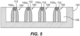
- powder bed 120 is used as a method for depositing material 112 through a powder bed fusion process.
- the powder bed fusion process can include direct metal laser sintering (DMLS), Electron beam melting (EBM), Selective heat sintering (SHS), Selective laser melting (SLM) and Selective laser sintering (SLS).
- Powder bed 120 includes powder material 122 that is consolidated by fusion onto deposition surface 110 proximate to damaged area 104 of air data probe 100 to form deposited material 112.
- Plugs 102a, 106a and 108a assist in preventing and/or limiting powder material 122 from entering into ports 102, 106, 108 of air data probe 100 during the fusion process.
- a similar powder bed 120 fusion process can readily be applied to repairing damaged port inlets 108 and/or 106. Those skilled in the art will readily appreciate that more than one probe can be repaired at once using powder bed 120. Additionally, it is contemplated that the powder bed fusion process would be performed with probe 100 removed from the aircraft.
- embodiments of the present invention also provide for methods to repair a damaged portion of another sense port inlet, e.g. an angle of attack port and/or a static pressure port, an angle of sideslip port, or a drain port, that opens in a direction transverse to a longitudinal axis A of an air data probe 200.
- air data probe 200 is shown with a damaged area 204 around a sense port inlet 206, e.g. an angle of attack port inlet 206.
- the method includes plugging sense port inlets 208 and 210 (damaged or not) with respective plugs 208a and 210a to limit contamination from entering air data probe 200 during repair.
- the repair method includes machining away the damaged and/or corroded area 204 around sense port inlet 206 and enlarging sense port inlet 206.
- sense port inlet 206 is oversized compared to its original size because the enlargement is complete as shown in Fig. 7 .
- the enlargement can be performed by drilling, milling, or any other suitable machining or material removal process, and the enlarged port inlet 206 can optionally be chamfered to help with joint penetration later in the process, which is described below.
- the method includes inserting a plug 206a into the now enlarged sense port inlet 206.
- plug 206a can be secured to enlarged sense port inlet 206 by welding, brazing, or simply with a tight fit.
- Plug 206a includes an enlarged head 216 and an insert portion 218. When insert portion 218 is inserted in enlarged sense port 206, enlarged head 216 prevents over insertion of plug 206a.
- plug 206a is not a temporary plug, but instead provides a deposition surface for adding material during the additive process.
- Plug 206a can be of the same material as air data probe 200, for example to allow autogenous welding as described below, or of any other suitable material.
- plug 206a can be made of the same material.
- plug 206a and/or deposited material 212 described below, includes an alloy having a higher wear resistance and/or a higher corrosion resistance than other portions of the probe body of air data probe 200.
- the method includes depositing a material 212 over and around plug 206a.
- Depositing material 212 includes depositing material 212 using at least one of directed energy deposition or powder bed fusion, similar to the powder bed fusion processes described above and as shown in Fig. 5 .
- the method includes machining deposited material 212 to conform to a specified geometry. Once machined to that specified geometry, e.g. to be flush with the existing probe surface, as shown in Fig. 10 , a new sense port 220 is formed in substantially the same position as plug 206a, as shown in Fig. 11 .
- new sense port 220 is formed in air data probe 200 in substantially the same position where original sense port 206 was located.
- new sense port 220 can be formed through center of plug 206a, or near the center.
- the position for forming sense port 220 can be determined based on at least one other port location in air data probe 200, e.g., using static port 210.
- New sense port 220 can be formed by drilling, milling, or any other suitable process. After new sense port 220 is formed, air data probe 200 can be degreased, flushed, and/or tested for suitability to return to service as needed.
- air data probe 200 includes a static port 208 and a newly formed angle of attack sense port 220. At least a portion of the wall surrounding the newly formed angle of attack sense port 220 is defined by deposited material 212 and/or plug 206a which can have a different microstructure than a material that defined wall 215 of air data probe 200 prior to repair.
- the microstructure of deposited material 212 can have better structural qualities (such as those described below with respect to wear and/or corrosion resistance) than material 215, or they can be the same.
- deposited material 212 includes an alloy having at least one of a higher wear resistance or a higher corrosion resistance than material 215, or deposited material 212 can be the same as material 215.
- the sense port repaired can be a type selected from the group consisting of an angle of attack port, a static port, an angle of sideslip port, and a drain port.
- direct material deposition can be used to repair other corroded or damaged areas separate from the various sense ports, such as a side wall of the air data probe.
Landscapes
- Engineering & Computer Science (AREA)
- Aviation & Aerospace Engineering (AREA)
- Manufacturing & Machinery (AREA)
- Chemical & Material Sciences (AREA)
- Materials Engineering (AREA)
- Physics & Mathematics (AREA)
- General Physics & Mathematics (AREA)
- Composite Materials (AREA)
- Mechanical Engineering (AREA)
- Transportation (AREA)
- Testing Resistance To Weather, Investigating Materials By Mechanical Methods (AREA)
Abstract
Description
- The present disclosure relates to air data probes and more particularly to air data probes for aerospace applications.
- A variety of air data probe devices are known in the art for aircraft flight control. Of such devices, many are directed to measuring Pitot pressure, static pressure, local angle of attack pressures, and angle of sideslip pressures as parameters for calculating pressure altitude, altitude rate, airspeed, Mach number, angle of attack, and angle of sideslip. The air data probe typically includes a Pitot pressure port located at the tip of the air data probe aligned with the longitudinal axis of the probe and/or one or more static pressure ports located on the side of the probe head integral to the probe's surface which sense the atmospheric pressure outside of the aircraft. When these pressure ports take consistent pressure measurements, they can provide accurate and consistent calculations of the above mentioned parameters.
- In ordinary use, exposure to the elements can eventually cause corrosion of the sensor ports and other portions of the probe device. Additionally, air data probe devices can be damaged during handling, such as during a pre-flight check. Such corrosion and deformation can alter the geometry of the sensor ports. This can reduce accuracy, and if the reduction in accuracy is substantial enough the probe must be replaced in order to resume accurate and consistent calculations parameters like those listed above.
- Such conventional methods and systems have generally been considered satisfactory for their intended purpose. However, there is still a need in the art for repair methods for restoration of proper function. There also remains a need in the art for such repairs that are easy to make.
- A method of repairing an air data probe includes assessing an air data probe for a damaged portion. The method includes depositing a material on the air data probe to repair the damaged portion of the air data probe.
- In accordance with some embodiments, the method includes scanning the air data probe with an optical inspection device to assess an amount and a location of damage. The method can include machining the damaged portion of an air data probe. The air data probe can include at least one sense port inlet. The method can include temporarily plugging the at least one sense port inlet to limit contamination from entering the air data probe during material deposition, and/or other stages of repair. Depositing the material can include depositing the material using at least one of directed energy deposition or powder bed fusion. The method can include machining the material to conform to a specified geometry. Machining the damaged portion of the air data probe can include removing corrosion from the damaged area.
- In accordance with some embodiments, the material includes an alloy having at least one of a higher wear resistance or a higher corrosion resistance than an original material of the air data probe. The material can include an alloy having better thermal performance than an original material of the air data probe. The material can include the original material of the air data probe. The air data probe can be mounted to an aircraft during material deposition. The damaged portion can be a damaged sense port inlet. The damaged sense port inlet can be defined through a tip of the air data probe. The damaged sense port inlet can be a Pitot pressure port inlet, an angle of attack port, a static port, an angle of sideslip port, and/or a drain port. The method can include inserting a plug into the damaged sense port inlet. The method can include welding or otherwise securing the plug into the damaged sense port inlet. Depositing the material can include depositing material over and around the plug. The method includes machining the deposited material and/or plug to conform to a specified geometry and forming a new sense port in substantially the same position as the plug. The method includes forming a new sense port in substantially the same position as the plug.
- In accordance with yet another aspect, an air data probe includes a probe body including a sense port inlet defined through a wall of the probe body. At least a portion of the wall surrounding the sense port inlet is defined by a deposited material having a different microstructure than a material defining another portion of the wall.
- In accordance with some embodiments, the sense port inlet is a Pitot pressure port inlet defined on a tip of the probe body. The sense port inlet can be surrounded at least in part with a plug mounted in the wall of the probe body. The deposited material can include an alloy having at least one of a higher wear resistance or a higher corrosion resistance than the material defining another portion of the wall.
- These and other features of the systems and methods of the subject invention will become more readily apparent to those skilled in the art from the following detailed description taken in conjunction with the drawings.
- So that those skilled in the art to which the subject invention appertains will readily understand how to make and use the devices and methods of the subject invention without undue experimentation, certain embodiments thereof will be described in detail herein below with reference to certain figures, wherein:
-
Fig. 1A is a perspective view of a portion of an exemplary embodiment of an air data probe constructed in accordance with embodiments of the present disclosure, showing a damaged area around the Pitot pressure port; -
Fig. 1B a schematic side cross-sectional view of a portion of an exemplary embodiment of an air data probe constructed in accordance with embodiments of the present disclosure, showing a damaged area around the Pitot pressure port; -
Fig. 2A is a perspective view of the air data probe ofFig. 1 , showing a stage of repair associated with machining away the damaged area around the Pitot pressure port to generate a uniform deposition surface in accordance with embodiments of the present disclosure; -
Fig. 2B is a schematic side cross-sectional view of the air data probe ofFig. 1 , showing a stage of repair associated with machining away the damaged area around the Pitot pressure port to generate a uniform deposition surface in accordance with embodiments of the present disclosure; -
Fig. 3 is a schematic side cross-sectional view of the air data probe ofFig. 1 , showing a stage of repair associated with depositing a material on the deposition surface of the air data probe to repair the damaged portion of the air data probe in accordance with embodiments of the present disclosure; -
Fig. 4 is a schematic side cross-sectional view of the air data probe ofFig. 1 , showing the repaired air data probe ofFig. 1 where the deposited material has been machined to conform to a specified geometry in accordance with embodiments of the present disclosure; -
Fig. 5 is a schematic side cross-sectional view of exemplary embodiments of air data probes, showing a stage of repair associated with depositing a material on the deposition surface of the air data probe by powder bed deposition in accordance with embodiments of the present disclosure; -
Fig. 6 is a schematic perspective view of a portion of another exemplary embodiment of an air data probe constructed in accordance with the embodiments of the present disclosure, showing a damaged area around the angle of attack port; -
Fig. 7 is a schematic perspective view of a portion of the air data probe ofFig. 6 , showing a repair stage after machining away the damaged area around the angle of attack port by enlarging the angle of attack port in accordance with embodiments of the present disclosure; -
Fig. 8 is a schematic perspective view of a portion of the air data probe ofFig. 6 , showing a repair stage associated with plugging the angle of attack port in accordance with embodiments of the present disclosure; -
Fig. 9 is a schematic perspective view of a portion of the air data probe ofFig. 6 , showing a repair stage after depositing the material on the air data probe over and around the plug in accordance with embodiments of the present disclosure; -
Fig. 10 is a perspective view of the air data probe ofFig. 6 , showing a repair stage after the deposited material has been machined to conform to a specified geometry in accordance with embodiments of the present disclosure; -
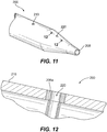
Fig. 11 is a perspective view of the air data probe ofFig. 6 , showing a new port positioned in substantially the same position as the original damaged or corroded angle of attack port; and -
Fig. 12 is a cross-sectional side elevation view of a portion of the air data probe ofFig. 6 , showing the new sense port formed through deposited material and the plug. - Reference will now be made to the drawings wherein like reference numerals identify similar structural features or aspects of the subject invention. For purposes of explanation and illustration, and not limitation, a partial view of an exemplary embodiment of air data probe repair in accordance with the invention is shown in
Fig. 1A and is designated generally byreference character 100. Other embodiments of air data probe repair in accordance with the invention, or aspects thereof, are provided inFigs. 1B-12 , as will be described. The methods and systems of the invention can be used for repair of air data probes with corroded or otherwise damaged sense ports, to improve or restore probe functional performance. - As shown in
Figs. 1A and 1B , anair data probe 100 includes a Pitotpressure port inlet 102 opening in a direction that is substantially parallel to the longitudinal axis A ofair data probe 100. In addition toport inlet 102,probe 100 includes additional sense port inlets, shown as astatic port 106 and an angle ofattack port 108. There is a damagedarea 104 aroundport inlet 102. In order to determine the extent and/or location of the damage,air data probe 100 is assessed by scanningair data probe 100 with an optical inspection device or by analyzed via metrology. Assessingair data probe 100 acts to identify a damaged portion with a reasonable degree of accuracy. In other words, some damage may exist outside of the portion identified as damaged and some non-damaged portion may exist within the portion that is identified as damaged. - With continued reference to
Fig. 1A , a method for repairingair data probe 100 includes temporarily pluggingsense port inlets plugs air data probe 100 during machining and/ormaterial 112 deposition.Plugs air data probe 100, which could have deleterious effects onprobe 100 function. While eachplug enlarged head 116 andinsert portion 118, which form a t-shaped cross-section, this is exemplary only. Any other suitable cross-section can be used, for example frustoconical, without departing from the scope of this disclosure. - As shown in
Fig. 2A ,port inlet 102 can also be plugged with aplug 102a. If needed, plug 102a can include an enlarged head similar toplugs air data probe 100 while it is still mounted to an aircraft. For on-aircraft repair, probe 100 would be scanned or analyzed via metrology and material would be deposited (similar to the method on-ground). For machining the deposited material, a special tooling suitable for on-aircraft use can be used to reshape the probe features. - As shown in
Figs. 2A and 2B , once plugged, repairingair data probe 100 includes machining damaged area/portion 104 ofair data probe 100 to generate adeposition surface 110. InFigs. 2A and 2B , damagedportion 104 has been machined away to form auniform deposition surface 110. In accordance with some embodiments, machining damagedportion 104 ofair data probe 100 includes removing corrosion from damagedarea 104. - As shown in
Fig. 3 , to repairair data probe 100,material 112 is deposited onuniform deposition surface 110 ofair data probe 100 to repair damagedportion 104 ofair data probe 100. Depositingmaterial 112 ondeposition surface 110 includes depositingmaterial 112 using at least one of directed energy deposition or powder bed fusion.Fig. 3 showsair data probe 100 with depositedmaterial 112. In this embodiment, depositedmaterial 112 includes an alloy having higher wear resistance and/or a higher corrosion resistance than anoriginal material 114 ofair data probe 100, or the same asoriginal material 114. It is also contemplated that, in some embodiments, depositedmaterial 112 includes an alloy having better thermal performance thanoriginal material 114 ofair data probe 100, or the same material asoriginal material 114. For example,original material 114 could benickel 200, 201 and/or 211, while depositednew material 112 could be a nickel super alloy, like INCONEL® 625 alloy, available from Specialty Metals Corporation of New Hartford, New York, cobalt chrome, titanium, or the like. In accordance with some embodiments, depositedmaterial 112 can be the same asoriginal material 114 with respect to all properties, e.g. depositedmaterial 112 is the same asoriginal material 114. With reference now toFig. 4 , the method includes machining depositedmaterial 112 to conform to a specified geometry.Fig. 4 shows probe 100 with machining completed. As such,plug 102a has been removed. It is also contemplated thatplugs - With reference now to
Fig. 5 ,powder bed 120 is used as a method for depositingmaterial 112 through a powder bed fusion process. Those skilled in the art will readily appreciate that the powder bed fusion process can include direct metal laser sintering (DMLS), Electron beam melting (EBM), Selective heat sintering (SHS), Selective laser melting (SLM) and Selective laser sintering (SLS).Powder bed 120 includespowder material 122 that is consolidated by fusion ontodeposition surface 110 proximate to damagedarea 104 ofair data probe 100 to form depositedmaterial 112.Plugs powder material 122 from entering intoports air data probe 100 during the fusion process. Asimilar powder bed 120 fusion process can readily be applied to repairing damagedport inlets 108 and/or 106. Those skilled in the art will readily appreciate that more than one probe can be repaired at once usingpowder bed 120. Additionally, it is contemplated that the powder bed fusion process would be performed withprobe 100 removed from the aircraft. - As shown in
Figs. 6-11 , embodiments of the present invention also provide for methods to repair a damaged portion of another sense port inlet, e.g. an angle of attack port and/or a static pressure port, an angle of sideslip port, or a drain port, that opens in a direction transverse to a longitudinal axis A of anair data probe 200. With reference now toFig. 6 ,air data probe 200 is shown with a damagedarea 204 around asense port inlet 206, e.g. an angle ofattack port inlet 206. The method includes pluggingsense port inlets 208 and 210 (damaged or not) withrespective plugs air data probe 200 during repair. - With reference now to
Fig. 7 , the repair method includes machining away the damaged and/or corrodedarea 204 aroundsense port inlet 206 and enlargingsense port inlet 206. As shown inFig. 7 ,sense port inlet 206 is oversized compared to its original size because the enlargement is complete as shown inFig. 7 . The enlargement can be performed by drilling, milling, or any other suitable machining or material removal process, and theenlarged port inlet 206 can optionally be chamfered to help with joint penetration later in the process, which is described below. - The method includes inserting a
plug 206a into the now enlargedsense port inlet 206. In accordance with some embodiments, plug 206a can be secured to enlargedsense port inlet 206 by welding, brazing, or simply with a tight fit.Plug 206a includes anenlarged head 216 and aninsert portion 218. Wheninsert portion 218 is inserted inenlarged sense port 206,enlarged head 216 prevents over insertion ofplug 206a. In the embodiment ofFig. 8 , plug 206a is not a temporary plug, but instead provides a deposition surface for adding material during the additive process.Plug 206a can be of the same material asair data probe 200, for example to allow autogenous welding as described below, or of any other suitable material. For example, if the probe body ofair data probe 200 is of NI200 ASTM B160, plug 206a can be made of the same material. In accordance with some embodiments, plug 206a and/or depositedmaterial 212, described below, includes an alloy having a higher wear resistance and/or a higher corrosion resistance than other portions of the probe body ofair data probe 200. - With reference now to
Fig. 9 , the method includes depositing amaterial 212 over and around plug 206a. Depositingmaterial 212 includes depositingmaterial 212 using at least one of directed energy deposition or powder bed fusion, similar to the powder bed fusion processes described above and as shown inFig. 5 . After depositingmaterial 212 over and around plug 206a, the method includes machining depositedmaterial 212 to conform to a specified geometry. Once machined to that specified geometry, e.g. to be flush with the existing probe surface, as shown inFig. 10 , anew sense port 220 is formed in substantially the same position asplug 206a, as shown inFig. 11 . - With reference to
Fig. 11 ,new sense port 220 is formed inair data probe 200 in substantially the same position whereoriginal sense port 206 was located. For example,new sense port 220 can be formed through center ofplug 206a, or near the center. The position for formingsense port 220 can be determined based on at least one other port location inair data probe 200, e.g., usingstatic port 210.New sense port 220 can be formed by drilling, milling, or any other suitable process. Afternew sense port 220 is formed,air data probe 200 can be degreased, flushed, and/or tested for suitability to return to service as needed. - With reference to
Fig. 12 ,air data probe 200 includes astatic port 208 and a newly formed angle ofattack sense port 220. At least a portion of the wall surrounding the newly formed angle ofattack sense port 220 is defined by depositedmaterial 212 and/or plug 206a which can have a different microstructure than a material that definedwall 215 ofair data probe 200 prior to repair. In accordance with some embodiments, the microstructure of depositedmaterial 212 can have better structural qualities (such as those described below with respect to wear and/or corrosion resistance) thanmaterial 215, or they can be the same. In accordance with some embodiments, depositedmaterial 212 includes an alloy having at least one of a higher wear resistance or a higher corrosion resistance thanmaterial 215, or depositedmaterial 212 can be the same asmaterial 215. - While shown and described above in the exemplary context of repairing a Pitot pressure port and an angle of attack sense port, those skilled in the art will readily appreciate that any other suitable type of port can be repaired in accordance with the invention. For example, the sense port repaired can be a type selected from the group consisting of an angle of attack port, a static port, an angle of sideslip port, and a drain port. Moreover, direct material deposition can be used to repair other corroded or damaged areas separate from the various sense ports, such as a side wall of the air data probe.
- The methods and systems of the present invention, as described above and shown in the drawings, provide for air data probe repair with superior properties including repair of sense ports that are corroded or otherwise damaged. The ability to repair air data probes reduces overall costs, as instead of replacing an air data probe, the air data probe can be repaired. While the apparatus and methods of the subject invention have been shown and described with reference to illustrative embodiments, those skilled in the art will readily appreciate that changes and/or modifications may be made thereto without departing from the scope of the subject invention.
Claims (15)
- A method of repairing an air data probe (100) comprising:assessing an air data probe (100) for a damaged portion; anddepositing a material on the air data probe (100) to repair the damaged portion of the air data probe (100).
- A method as recited in claim 1, further comprising scanning the air data probe (100) with an optical inspection device to assess an amount and a location of damage, and/or
further comprising machining the damaged portion of an air data probe (100) to generate a machined portion. - A method as recited in any preceding claim, wherein the air data probe (100) incudes at least one sense port inlet, and the method includes temporarily plugging the at least one sense port inlet (106,108) to limit contamination from entering the air data probe (100) during repair.
- A method as recited in any preceding claim, wherein depositing the material includes depositing the material using at least one of directed energy deposition or powder bed fusion.
- A method as recited in any preceding claim, further comprising machining the material to conform to a specified geometry.
- A method as recited in any preceding claim, wherein the material includes an alloy having at least one of a higher wear resistance or a higher corrosion resistance than an original material of the air data probe, or wherein the material includes an alloy having better thermal performance than an original material of the air data probe (100).
- A method as recited in any preceding claim, wherein the air data probe (100) is mounted to an aircraft during material deposition.
- A method as recited in any preceding claim, wherein the damaged portion is a damaged sense port inlet.
- A method as recited in claim 8, further comprising temporarily plugging the damaged sense port inlet to limit contamination from entering the air data probe during repair, or
wherein the damaged sense port inlet is defined through a tip of the air data probe, or wherein the damaged sense port inlet is a Pitot pressure port inlet. - A method as recited in claim 8, wherein the damaged sense port inlet is at least one of an angle of attack port inlet, a static port inlet, an angle of sideslip port inlet, or a drain port inlet.
- A method as recited in claim 8, further comprising inserting a plug (106a, 106b) into the damaged sense port inlet.
- A method as recited in claim 10, wherein depositing the material includes depositing material over and around the plug, and optionally
further comprising machining at least one of the deposited material or plug to conform to a specified geometry and forming a new sense port in substantially the same position as the plug. - An air data probe (100) comprising:
a probe body including a sense port inlet (106,108) defined through a wall of the probe body, wherein at least a portion of the wall surrounding the sense port inlet (106,108) is defined by a deposited material having a different microstructure than a material defining another portion of the wall. - An air data probe as recited in claim 13, wherein the sense port inlet (106,108) is a Pitot pressure port inlet defined on a tip of the probe body.
- An air data probe as recited in claim 13 or 14, wherein the sense port inlet (106,108) is surrounded at least in part with a plug (106a,106b) mounted in the wall of the probe body.
Applications Claiming Priority (1)
| Application Number | Priority Date | Filing Date | Title |
|---|---|---|---|
| US16/159,319 US10780502B2 (en) | 2018-10-12 | 2018-10-12 | Air data probe repair |
Publications (2)
| Publication Number | Publication Date |
|---|---|
| EP3637111A1 true EP3637111A1 (en) | 2020-04-15 |
| EP3637111B1 EP3637111B1 (en) | 2022-11-30 |
Family
ID=68280747
Family Applications (1)
| Application Number | Title | Priority Date | Filing Date |
|---|---|---|---|
| EP19202541.9A Active EP3637111B1 (en) | 2018-10-12 | 2019-10-10 | Air data probe repair |
Country Status (2)
| Country | Link |
|---|---|
| US (1) | US10780502B2 (en) |
| EP (1) | EP3637111B1 (en) |
Families Citing this family (8)
| Publication number | Priority date | Publication date | Assignee | Title |
|---|---|---|---|---|
| US11209330B2 (en) | 2015-03-23 | 2021-12-28 | Rosemount Aerospace Inc. | Corrosion resistant sleeve for an air data probe |
| US11414195B2 (en) | 2018-03-23 | 2022-08-16 | Rosemount Aerospace Inc. | Surface modified heater assembly |
| US11002754B2 (en) | 2018-11-06 | 2021-05-11 | Rosemount Aerospace Inc. | Pitot probe with mandrel and pressure swaged outer shell |
| US10884014B2 (en) | 2019-03-25 | 2021-01-05 | Rosemount Aerospace Inc. | Air data probe with fully-encapsulated heater |
| US11428707B2 (en) | 2019-06-14 | 2022-08-30 | Rosemount Aerospace Inc. | Air data probe with weld sealed insert |
| US11624637B1 (en) | 2021-10-01 | 2023-04-11 | Rosemount Aerospace Inc | Air data probe with integrated heater bore and features |
| US11662235B2 (en) | 2021-10-01 | 2023-05-30 | Rosemount Aerospace Inc. | Air data probe with enhanced conduction integrated heater bore and features |
| US11885262B1 (en) | 2023-02-10 | 2024-01-30 | Pratt & Whitney Canada Corp. | Repairs for defects in bores |
Citations (4)
| Publication number | Priority date | Publication date | Assignee | Title |
|---|---|---|---|---|
| US3355946A (en) * | 1965-01-19 | 1967-12-05 | Lazell Robert Charles | Pitot tubes |
| EP2787353A1 (en) * | 2013-04-02 | 2014-10-08 | Rosemount Aerospace Inc. | Air data probe sense port repair |
| GB2521048A (en) * | 2013-11-06 | 2015-06-10 | Bae Systems Plc | Conduit |
| EP3190419A1 (en) * | 2016-01-08 | 2017-07-12 | Honeywell International Inc. | Probe tip for air data probe |
Family Cites Families (2)
| Publication number | Priority date | Publication date | Assignee | Title |
|---|---|---|---|---|
| US20160304210A1 (en) | 2014-10-15 | 2016-10-20 | Rosemount Aerospace Inc. | One-piece air data probe |
| JP6450158B2 (en) * | 2014-11-13 | 2019-01-09 | 三菱航空機株式会社 | Method for identifying processing position in repair material and repair method |
-
2018
- 2018-10-12 US US16/159,319 patent/US10780502B2/en active Active
-
2019
- 2019-10-10 EP EP19202541.9A patent/EP3637111B1/en active Active
Patent Citations (4)
| Publication number | Priority date | Publication date | Assignee | Title |
|---|---|---|---|---|
| US3355946A (en) * | 1965-01-19 | 1967-12-05 | Lazell Robert Charles | Pitot tubes |
| EP2787353A1 (en) * | 2013-04-02 | 2014-10-08 | Rosemount Aerospace Inc. | Air data probe sense port repair |
| GB2521048A (en) * | 2013-11-06 | 2015-06-10 | Bae Systems Plc | Conduit |
| EP3190419A1 (en) * | 2016-01-08 | 2017-07-12 | Honeywell International Inc. | Probe tip for air data probe |
Also Published As
| Publication number | Publication date |
|---|---|
| EP3637111B1 (en) | 2022-11-30 |
| US10780502B2 (en) | 2020-09-22 |
| US20200114428A1 (en) | 2020-04-16 |
Similar Documents
| Publication | Publication Date | Title |
|---|---|---|
| EP3637111B1 (en) | Air data probe repair | |
| US9279684B2 (en) | Air data probe sense port repair | |
| CN102481668B (en) | Automated maintenance method and system | |
| CN108959701B (en) | Composite part, method for forming composite part and associated storage medium | |
| US8218001B2 (en) | Performing a process on a workpiece | |
| WO2007036437A1 (en) | Method of producing a gas turbine component to be coated having exposed openings, apparatus for carrying out the method, and coatable turbine blade having a film-cooling opening | |
| EP3936278B1 (en) | Method of repairing a combustor liner of a gas turbine engine | |
| EP1739410A1 (en) | Systems and methods for determining the location and angular orientation of a hole with an obstructed opening residing on a surface of an article | |
| DE102014222159A1 (en) | Repair method and apparatus for generatively repairing a component | |
| US11137320B2 (en) | Method for producing a pressure sensor measuring element and thus obtained pressure sensor measuring element | |
| WO2011047995A1 (en) | Surface analysis for detecting closed holes, and device | |
| WO2017021532A1 (en) | Method for repairing a damaged workpiece | |
| EP2508844A1 (en) | Method for determining the thickness of a coating | |
| WO2020011673A1 (en) | Device and method for analyzing the surface of parts having cooling fluid openings | |
| CN114959684A (en) | Repair method of sealing surface of valve main seat | |
| Pillari et al. | Additively Manufactured Wind Tunnel Balance Cooling Shields | |
| WO2020011674A1 (en) | Device and method for removing coating material from openings in a part | |
| EP4414123A1 (en) | Repairs for defects in bores | |
| Anderson et al. | Additive Manufacturing Fan Housings for the Universal Waste Management System Using the Electron-Beam Powder Bed Fusion Process | |
| DE102019217580A1 (en) | Repair of coated components by means of design adaptation | |
| DE102013225917A1 (en) | Method and device for reopening holes in a component after a coating process | |
| DE102013226217A1 (en) | Repair of gas turbine components using scrap parts | |
| Bender | Mechanical Devices Readiness FY04. 0402.1 | |
| DE29723374U1 (en) | Precise measurement in a wall |
Legal Events
| Date | Code | Title | Description |
|---|---|---|---|
| PUAI | Public reference made under article 153(3) epc to a published international application that has entered the european phase |
Free format text: ORIGINAL CODE: 0009012 |
|
| STAA | Information on the status of an ep patent application or granted ep patent |
Free format text: STATUS: THE APPLICATION HAS BEEN PUBLISHED |
|
| AK | Designated contracting states |
Kind code of ref document: A1 Designated state(s): AL AT BE BG CH CY CZ DE DK EE ES FI FR GB GR HR HU IE IS IT LI LT LU LV MC MK MT NL NO PL PT RO RS SE SI SK SM TR |
|
| AX | Request for extension of the european patent |
Extension state: BA ME |
|
| STAA | Information on the status of an ep patent application or granted ep patent |
Free format text: STATUS: REQUEST FOR EXAMINATION WAS MADE |
|
| 17P | Request for examination filed |
Effective date: 20201015 |
|
| RBV | Designated contracting states (corrected) |
Designated state(s): AL AT BE BG CH CY CZ DE DK EE ES FI FR GB GR HR HU IE IS IT LI LT LU LV MC MK MT NL NO PL PT RO RS SE SI SK SM TR |
|
| GRAP | Despatch of communication of intention to grant a patent |
Free format text: ORIGINAL CODE: EPIDOSNIGR1 |
|
| STAA | Information on the status of an ep patent application or granted ep patent |
Free format text: STATUS: GRANT OF PATENT IS INTENDED |
|
| RIC1 | Information provided on ipc code assigned before grant |
Ipc: C22C 1/04 20060101ALN20220425BHEP Ipc: G01P 21/02 20060101ALN20220425BHEP Ipc: B64F 5/40 20170101ALI20220425BHEP Ipc: B22F 10/20 20210101ALI20220425BHEP Ipc: B22F 7/06 20060101ALI20220425BHEP Ipc: G01P 13/02 20060101ALI20220425BHEP Ipc: B64D 43/02 20060101ALI20220425BHEP Ipc: B33Y 10/00 20150101ALI20220425BHEP Ipc: G01P 5/165 20060101AFI20220425BHEP |
|
| INTG | Intention to grant announced |
Effective date: 20220511 |
|
| RIC1 | Information provided on ipc code assigned before grant |
Ipc: C22C 1/04 20060101ALN20220429BHEP Ipc: G01P 21/02 20060101ALN20220429BHEP Ipc: B64F 5/40 20170101ALI20220429BHEP Ipc: B22F 10/20 20210101ALI20220429BHEP Ipc: B22F 7/06 20060101ALI20220429BHEP Ipc: G01P 13/02 20060101ALI20220429BHEP Ipc: B64D 43/02 20060101ALI20220429BHEP Ipc: B33Y 10/00 20150101ALI20220429BHEP Ipc: G01P 5/165 20060101AFI20220429BHEP |
|
| GRAS | Grant fee paid |
Free format text: ORIGINAL CODE: EPIDOSNIGR3 |
|
| GRAA | (expected) grant |
Free format text: ORIGINAL CODE: 0009210 |
|
| STAA | Information on the status of an ep patent application or granted ep patent |
Free format text: STATUS: THE PATENT HAS BEEN GRANTED |
|
| AK | Designated contracting states |
Kind code of ref document: B1 Designated state(s): AL AT BE BG CH CY CZ DE DK EE ES FI FR GB GR HR HU IE IS IT LI LT LU LV MC MK MT NL NO PL PT RO RS SE SI SK SM TR |
|
| REG | Reference to a national code |
Ref country code: CH Ref legal event code: EP Ref country code: GB Ref legal event code: FG4D |
|
| REG | Reference to a national code |
Ref country code: AT Ref legal event code: REF Ref document number: 1535050 Country of ref document: AT Kind code of ref document: T Effective date: 20221215 |
|
| REG | Reference to a national code |
Ref country code: IE Ref legal event code: FG4D |
|
| REG | Reference to a national code |
Ref country code: DE Ref legal event code: R096 Ref document number: 602019022471 Country of ref document: DE |
|
| REG | Reference to a national code |
Ref country code: LT Ref legal event code: MG9D |
|
| REG | Reference to a national code |
Ref country code: NL Ref legal event code: MP Effective date: 20221130 |
|
| PG25 | Lapsed in a contracting state [announced via postgrant information from national office to epo] |
Ref country code: SE Free format text: LAPSE BECAUSE OF FAILURE TO SUBMIT A TRANSLATION OF THE DESCRIPTION OR TO PAY THE FEE WITHIN THE PRESCRIBED TIME-LIMIT Effective date: 20221130 Ref country code: PT Free format text: LAPSE BECAUSE OF FAILURE TO SUBMIT A TRANSLATION OF THE DESCRIPTION OR TO PAY THE FEE WITHIN THE PRESCRIBED TIME-LIMIT Effective date: 20230331 Ref country code: NO Free format text: LAPSE BECAUSE OF FAILURE TO SUBMIT A TRANSLATION OF THE DESCRIPTION OR TO PAY THE FEE WITHIN THE PRESCRIBED TIME-LIMIT Effective date: 20230228 Ref country code: LT Free format text: LAPSE BECAUSE OF FAILURE TO SUBMIT A TRANSLATION OF THE DESCRIPTION OR TO PAY THE FEE WITHIN THE PRESCRIBED TIME-LIMIT Effective date: 20221130 Ref country code: FI Free format text: LAPSE BECAUSE OF FAILURE TO SUBMIT A TRANSLATION OF THE DESCRIPTION OR TO PAY THE FEE WITHIN THE PRESCRIBED TIME-LIMIT Effective date: 20221130 Ref country code: ES Free format text: LAPSE BECAUSE OF FAILURE TO SUBMIT A TRANSLATION OF THE DESCRIPTION OR TO PAY THE FEE WITHIN THE PRESCRIBED TIME-LIMIT Effective date: 20221130 |
|
| REG | Reference to a national code |
Ref country code: AT Ref legal event code: MK05 Ref document number: 1535050 Country of ref document: AT Kind code of ref document: T Effective date: 20221130 |
|
| PG25 | Lapsed in a contracting state [announced via postgrant information from national office to epo] |
Ref country code: RS Free format text: LAPSE BECAUSE OF FAILURE TO SUBMIT A TRANSLATION OF THE DESCRIPTION OR TO PAY THE FEE WITHIN THE PRESCRIBED TIME-LIMIT Effective date: 20221130 Ref country code: PL Free format text: LAPSE BECAUSE OF FAILURE TO SUBMIT A TRANSLATION OF THE DESCRIPTION OR TO PAY THE FEE WITHIN THE PRESCRIBED TIME-LIMIT Effective date: 20221130 Ref country code: LV Free format text: LAPSE BECAUSE OF FAILURE TO SUBMIT A TRANSLATION OF THE DESCRIPTION OR TO PAY THE FEE WITHIN THE PRESCRIBED TIME-LIMIT Effective date: 20221130 Ref country code: IS Free format text: LAPSE BECAUSE OF FAILURE TO SUBMIT A TRANSLATION OF THE DESCRIPTION OR TO PAY THE FEE WITHIN THE PRESCRIBED TIME-LIMIT Effective date: 20230330 Ref country code: HR Free format text: LAPSE BECAUSE OF FAILURE TO SUBMIT A TRANSLATION OF THE DESCRIPTION OR TO PAY THE FEE WITHIN THE PRESCRIBED TIME-LIMIT Effective date: 20221130 Ref country code: GR Free format text: LAPSE BECAUSE OF FAILURE TO SUBMIT A TRANSLATION OF THE DESCRIPTION OR TO PAY THE FEE WITHIN THE PRESCRIBED TIME-LIMIT Effective date: 20230301 |
|
| PG25 | Lapsed in a contracting state [announced via postgrant information from national office to epo] |
Ref country code: NL Free format text: LAPSE BECAUSE OF FAILURE TO SUBMIT A TRANSLATION OF THE DESCRIPTION OR TO PAY THE FEE WITHIN THE PRESCRIBED TIME-LIMIT Effective date: 20221130 |
|
| PG25 | Lapsed in a contracting state [announced via postgrant information from national office to epo] |
Ref country code: SM Free format text: LAPSE BECAUSE OF FAILURE TO SUBMIT A TRANSLATION OF THE DESCRIPTION OR TO PAY THE FEE WITHIN THE PRESCRIBED TIME-LIMIT Effective date: 20221130 Ref country code: RO Free format text: LAPSE BECAUSE OF FAILURE TO SUBMIT A TRANSLATION OF THE DESCRIPTION OR TO PAY THE FEE WITHIN THE PRESCRIBED TIME-LIMIT Effective date: 20221130 Ref country code: EE Free format text: LAPSE BECAUSE OF FAILURE TO SUBMIT A TRANSLATION OF THE DESCRIPTION OR TO PAY THE FEE WITHIN THE PRESCRIBED TIME-LIMIT Effective date: 20221130 Ref country code: DK Free format text: LAPSE BECAUSE OF FAILURE TO SUBMIT A TRANSLATION OF THE DESCRIPTION OR TO PAY THE FEE WITHIN THE PRESCRIBED TIME-LIMIT Effective date: 20221130 Ref country code: CZ Free format text: LAPSE BECAUSE OF FAILURE TO SUBMIT A TRANSLATION OF THE DESCRIPTION OR TO PAY THE FEE WITHIN THE PRESCRIBED TIME-LIMIT Effective date: 20221130 Ref country code: AT Free format text: LAPSE BECAUSE OF FAILURE TO SUBMIT A TRANSLATION OF THE DESCRIPTION OR TO PAY THE FEE WITHIN THE PRESCRIBED TIME-LIMIT Effective date: 20221130 |
|
| PG25 | Lapsed in a contracting state [announced via postgrant information from national office to epo] |
Ref country code: SK Free format text: LAPSE BECAUSE OF FAILURE TO SUBMIT A TRANSLATION OF THE DESCRIPTION OR TO PAY THE FEE WITHIN THE PRESCRIBED TIME-LIMIT Effective date: 20221130 Ref country code: AL Free format text: LAPSE BECAUSE OF FAILURE TO SUBMIT A TRANSLATION OF THE DESCRIPTION OR TO PAY THE FEE WITHIN THE PRESCRIBED TIME-LIMIT Effective date: 20221130 |
|
| REG | Reference to a national code |
Ref country code: DE Ref legal event code: R097 Ref document number: 602019022471 Country of ref document: DE |
|
| PLBE | No opposition filed within time limit |
Free format text: ORIGINAL CODE: 0009261 |
|
| STAA | Information on the status of an ep patent application or granted ep patent |
Free format text: STATUS: NO OPPOSITION FILED WITHIN TIME LIMIT |
|
| 26N | No opposition filed |
Effective date: 20230831 |
|
| PG25 | Lapsed in a contracting state [announced via postgrant information from national office to epo] |
Ref country code: SI Free format text: LAPSE BECAUSE OF FAILURE TO SUBMIT A TRANSLATION OF THE DESCRIPTION OR TO PAY THE FEE WITHIN THE PRESCRIBED TIME-LIMIT Effective date: 20221130 |
|
| PG25 | Lapsed in a contracting state [announced via postgrant information from national office to epo] |
Ref country code: IT Free format text: LAPSE BECAUSE OF FAILURE TO SUBMIT A TRANSLATION OF THE DESCRIPTION OR TO PAY THE FEE WITHIN THE PRESCRIBED TIME-LIMIT Effective date: 20221130 Ref country code: MC Free format text: LAPSE BECAUSE OF FAILURE TO SUBMIT A TRANSLATION OF THE DESCRIPTION OR TO PAY THE FEE WITHIN THE PRESCRIBED TIME-LIMIT Effective date: 20221130 |
|
| REG | Reference to a national code |
Ref country code: CH Ref legal event code: PL |
|
| REG | Reference to a national code |
Ref country code: BE Ref legal event code: MM Effective date: 20231031 |
|
| PG25 | Lapsed in a contracting state [announced via postgrant information from national office to epo] |
Ref country code: LU Free format text: LAPSE BECAUSE OF NON-PAYMENT OF DUE FEES Effective date: 20231010 |
|
| PG25 | Lapsed in a contracting state [announced via postgrant information from national office to epo] |
Ref country code: LU Free format text: LAPSE BECAUSE OF NON-PAYMENT OF DUE FEES Effective date: 20231010 |
|
| PG25 | Lapsed in a contracting state [announced via postgrant information from national office to epo] |
Ref country code: CH Free format text: LAPSE BECAUSE OF NON-PAYMENT OF DUE FEES Effective date: 20231031 |
|
| PG25 | Lapsed in a contracting state [announced via postgrant information from national office to epo] |
Ref country code: CH Free format text: LAPSE BECAUSE OF NON-PAYMENT OF DUE FEES Effective date: 20231031 |
|
| PG25 | Lapsed in a contracting state [announced via postgrant information from national office to epo] |
Ref country code: BE Free format text: LAPSE BECAUSE OF NON-PAYMENT OF DUE FEES Effective date: 20231031 |
|
| PG25 | Lapsed in a contracting state [announced via postgrant information from national office to epo] |
Ref country code: IE Free format text: LAPSE BECAUSE OF NON-PAYMENT OF DUE FEES Effective date: 20231010 |
|
| PG25 | Lapsed in a contracting state [announced via postgrant information from national office to epo] |
Ref country code: IE Free format text: LAPSE BECAUSE OF NON-PAYMENT OF DUE FEES Effective date: 20231010 |
|
| PG25 | Lapsed in a contracting state [announced via postgrant information from national office to epo] |
Ref country code: BG Free format text: LAPSE BECAUSE OF FAILURE TO SUBMIT A TRANSLATION OF THE DESCRIPTION OR TO PAY THE FEE WITHIN THE PRESCRIBED TIME-LIMIT Effective date: 20221130 |
|
| PG25 | Lapsed in a contracting state [announced via postgrant information from national office to epo] |
Ref country code: BG Free format text: LAPSE BECAUSE OF FAILURE TO SUBMIT A TRANSLATION OF THE DESCRIPTION OR TO PAY THE FEE WITHIN THE PRESCRIBED TIME-LIMIT Effective date: 20221130 |
|
| PG25 | Lapsed in a contracting state [announced via postgrant information from national office to epo] |
Ref country code: CY Free format text: LAPSE BECAUSE OF FAILURE TO SUBMIT A TRANSLATION OF THE DESCRIPTION OR TO PAY THE FEE WITHIN THE PRESCRIBED TIME-LIMIT; INVALID AB INITIO Effective date: 20191010 |
|
| PG25 | Lapsed in a contracting state [announced via postgrant information from national office to epo] |
Ref country code: HU Free format text: LAPSE BECAUSE OF FAILURE TO SUBMIT A TRANSLATION OF THE DESCRIPTION OR TO PAY THE FEE WITHIN THE PRESCRIBED TIME-LIMIT; INVALID AB INITIO Effective date: 20191010 |
|
| PGFP | Annual fee paid to national office [announced via postgrant information from national office to epo] |
Ref country code: GB Payment date: 20250923 Year of fee payment: 7 |
|
| PGFP | Annual fee paid to national office [announced via postgrant information from national office to epo] |
Ref country code: FR Payment date: 20250924 Year of fee payment: 7 |
|
| PG25 | Lapsed in a contracting state [announced via postgrant information from national office to epo] |
Ref country code: TR Free format text: LAPSE BECAUSE OF FAILURE TO SUBMIT A TRANSLATION OF THE DESCRIPTION OR TO PAY THE FEE WITHIN THE PRESCRIBED TIME-LIMIT Effective date: 20221130 |
|
| PGFP | Annual fee paid to national office [announced via postgrant information from national office to epo] |
Ref country code: DE Payment date: 20250923 Year of fee payment: 7 |
|
| P01 | Opt-out of the competence of the unified patent court (upc) registered |
Free format text: CASE NUMBER: UPC_APP_0018982_3637111/2025 Effective date: 20251222 |