EP3637073A1 - Process for the temperature measurement for a high temperature micro-deformation device - Google Patents
Process for the temperature measurement for a high temperature micro-deformation device Download PDFInfo
- Publication number
- EP3637073A1 EP3637073A1 EP18199374.2A EP18199374A EP3637073A1 EP 3637073 A1 EP3637073 A1 EP 3637073A1 EP 18199374 A EP18199374 A EP 18199374A EP 3637073 A1 EP3637073 A1 EP 3637073A1
- Authority
- EP
- European Patent Office
- Prior art keywords
- sample
- temperature
- samples
- experiments
- temperatures
- Prior art date
- Legal status (The legal status is an assumption and is not a legal conclusion. Google has not performed a legal analysis and makes no representation as to the accuracy of the status listed.)
- Granted
Links
Images



Classifications
-
- G—PHYSICS
- G01—MEASURING; TESTING
- G01K—MEASURING TEMPERATURE; MEASURING QUANTITY OF HEAT; THERMALLY-SENSITIVE ELEMENTS NOT OTHERWISE PROVIDED FOR
- G01K1/00—Details of thermometers not specially adapted for particular types of thermometer
- G01K1/14—Supports; Fastening devices; Arrangements for mounting thermometers in particular locations
-
- G—PHYSICS
- G01—MEASURING; TESTING
- G01K—MEASURING TEMPERATURE; MEASURING QUANTITY OF HEAT; THERMALLY-SENSITIVE ELEMENTS NOT OTHERWISE PROVIDED FOR
- G01K7/00—Measuring temperature based on the use of electric or magnetic elements directly sensitive to heat ; Power supply therefor, e.g. using thermoelectric elements
- G01K7/42—Circuits effecting compensation of thermal inertia; Circuits for predicting the stationary value of a temperature
- G01K2007/422—Dummy objects used for estimating temperature of real objects
-
- G—PHYSICS
- G01—MEASURING; TESTING
- G01N—INVESTIGATING OR ANALYSING MATERIALS BY DETERMINING THEIR CHEMICAL OR PHYSICAL PROPERTIES
- G01N3/00—Investigating strength properties of solid materials by application of mechanical stress
- G01N3/40—Investigating hardness or rebound hardness
- G01N3/42—Investigating hardness or rebound hardness by performing impressions under a steady load by indentors, e.g. sphere, pyramid
Definitions
- Present invention relates to a process for the temperature detection of a sample the temperature of which cannot be measured directly and a device for measuring physical properties other than the temperature of a sample using two or more identical samples and a device for carrying out the process.
- Nano- and micromechanical characterization as an approach in understanding the materials of this generation is already well established. Apart from the microstructural features in materials, length scales of many components in the present electronic systems have shrinked by many orders of magnitudes. Micromechanical testing can reveal the deformation and fracture behaviour of these systems in their service conditions. The complete comprehension of these components is only possible after probing their response with varying temperatures. This facilitates a clear understanding of the qualitative and quantitative changes in the deformation processes of these systems at their working temperatures.
- thermocouples One aspect in these setups that can improve the reliability is the temperature measurement approach applied.
- Most of the successful known testing arrangements record the temperatures of the sample(s) near the heating sources but not at the respective surfaces. Measuring the temperatures at the position of interest is prevented due to (i) the small region of interest and (ii) undesired alterations of the microstructure of the material during the application of the thermocouples.
- Today the contact temperatures of the tip and the sample are assumed according to these temperatures directly or with various additional approaches of temperature matching like thermal displacement drift and indenter temperature shift measurements. These approaches can result in an error of 5-40% in the recorded temperature to the actual contact temperature especially at higher working temperatures.
- Some platforms tried to overcome these anomalies by calibrating the indenter to know the contact temperatures more precisely by approaches like indenting the thermocouples.
- Object of present invention is to provide a process with which estimating the temperature of a sample the temperature of which cannot be measured directly is possible and estimated easily with good reliability and short stabilization times.
- Subject matter of present invention is a process for the temperature detection of a sample the temperature of which cannot be measured directly in a device for measuring physical properties other than the temperature using two or more identical samples, characterized in that
- the process of present invention enables to estimate the temperature of sample the temperature of which cannot measured directly with good reliability and in the short time.
- two identical samples are used.
- identical samples mean that the samples have the same size and composition.
- One essential feature of present invention is that the samples have the same surrounding, this can be achieved by arranging the samples symmetrically. While the temperature is measured at one sample acting as the mirror sample, the physical experiments are carried out at the other sample(s), also called working sample(s). According to the process of present invention there can be used one or more working sample(s). In the following only the singular form sample is used although one sample or more mirror samples and working samples can be used. Since the samples are arranged symmetrically they have the same surrounding. Usually the surface temperature of the mirror sample is measured. From the temperature measured at the mirror sample can be referred to the temperature of the sample(s) with which the physical experiments have been carried out.
- the process of present invention is suitable for all processes wherein physical properties have to be measured or physical experiments have to be carried out at a defined temperature and wherein the measurement of the temperature of the sample cannot be carried out simultaneously or wherein it is difficult to measure the temperature precisely.
- the process of present invention is especially advantageous for micromechanical experiments, i.e. experiments examining the mechanical properties of the material of the sample consists of, such as micro-fracture mechanics, micro tensile experiments, micro bending and compression experiments.
- the inventive process is especially suitable for high temperatures, for example at temperatures between ambient temperatures and 600°C.
- the process of present invention is suitable for samples in the micro scale, for example for thin films, micro cantilever beams, micro compression pillars etc in the micro scale, especially for samples having a size in the range of 1 to 30 ⁇ m.
- the samples are heated simultaneously, preferably with the same heating device.
- one heating device is used for all samples, i.e. for the mirror sample and for the working sample with which the experiments are carried out.
- the heating device is arranged in the centre between the samples. From the fact that the samples are arranged in the same measurement environment and heated in the same way manner, it can be concluded that the sample with which the experiments are carried out has the same temperature as the sample of the temperature of which is measured.
- Another subject of present invention is a device for the detection of physical properties of Device for the detection of physical properties of samples comprising a sample support with at least two sample holders, a measurement unit for measuring the temperature of the sample in one sample holders and one or more unit(s) for carrying out physical experiments at the sample in the other sample holder, wherein the sample holders are arranged so that they have the same measurement surrounding.
- the device of present invention is suitable for carrying out experiments and measurements over a broad size range, even in the macro-scale and in the micro-scale. Experiments in the micro-scale can be achieve with high accuracy and reliability.
- sample holders are arranged symmetrically.
- the heating system is preferably arranged in the centre between the samples.
- An example for a suitable heating system is a laser.
- the device may also comprise a cooling system.
- the device comprise two or more sample supports with at least two sample holders in each, a measurement unit for measuring the temperature of the sample in one sample holder and one or more unit(s) for carrying out physical experiments. That means the sample supports has a counter body, at both sample supports the same measurements can be carried out. Depending on the requirements for the measurement the sample supports can be moved in relation to another. In case at all sample supports the same experiments are carried out, from the results can be referred to the accuracy of the obtained results.
- a vacuum chamber may comprise one or more of the devices of present invention.
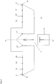
- Fig. 1 shows a device 1 for the detection of physical properties of samples having two sample holders 2 and 3, one for the working sample and one for the mirror sample.
- the device in fig. 1 has clamps 4 and 5.
- the basic body of the device, also called sample support 13 has a symmetrical design with regard to the axis A - A extending between the sample holders. The heat is supplied via the bottom of the device (not shown in fig. 1 ).
- Fig. 2 shows a miniature sample support 13.
- This support may have a size of 1.8 ⁇ 1.8 ⁇ 0.6 cm 3 and may be manufactured from Incoloy® 800 HT, a Nickel super alloy with high thermal conductivity (21.1 W/m°C at 600°C) for quick heat transfer and thermal stabilization.
- the support 13 comprises two different slots 2, 3 for the samples, once each for mirror sample and the working sample on which the experiments, for example deformation experiments, are carried out.
- the device according to present invention comprises two sample holders 2, 3 which are arranged equidistant from the heating source (not shown).
- a mechanical screw based metallic strip clamping system 4, 5 out of Inconel alloy is used to mount the samples.
- the heat flow from the sample support towards the sensitive electronic hardware is restricted by the use rods 14 having an extremely low thermal conductivity, for example of app. 3 W/mK.
- An example for a suitable material is Yttria stabilized Zirconia having a thermal conductivity of of 3 W/mK. From the thermal point of view these rods 14 are not visible, they do not have any influence on the temperature of the samples.
- a plate 15 is placed at the end of the rods for further restricting the heat transfer from the stage.
- the plate 15 may be made from glass ceramic such as Macor®.
- the device may be attached to holder plates 16, 17 and can be arranged in a measurement chamber.
- An additional copper braid (not shown) may be placed behind the rods which is connected to a water cooled copper block. This acts as a heat sink for the whole setup keeping the indenter hardware at cooler temperatures.
- a localized heat source in particular identical heat sources.
- diode laser systems of spot size 0.4 mm form Dilas Laser systems are suitable to achieve this.
- the required power required is calculated from cooling curves of heating experiments of the stage conducted with a flame torch.
- the two stages, one holding the working sample and the mirror sample and the other holding the counter body and the counter body of the mirror sample are heated from the bottom at the center of the stage with two separate laser systems.
- Type K thermocouples of 0.25 mm diameter are positioned along the arms of the stage symmetrically on both sides with one placed directly on the surface of the reference sample/tip.
- the two active reference thermocouples (the ones on the reference sample in sample stage and the reference counter body in the counter body stage), and the laser power controls are in turn connected to a Eurotherm controller providing a closed feedback loop to control the designated temperature and power.
- the indenter system is a straining rig with a force and displacement resolutions of 10 ⁇ m and 1 nm respectively.
- the whole system is placed in a steel chamber capable of attaining vacuum in the range of 10 -5 -10 -6 mbar.
- An inverted optical microscope may be used as a visual aid.
- Fig. 3 shows a cut along line A - A of the device of Fig. 2 having two a sample support 1, each with a sample holder 2 for the working sample and a sample holder 3 for the mirror sample.
- the sample supports are located within a measurement chamber 18.
- the working sample 2 and the mirror sample 3 are situated on the two arms of the device 1.
- the samples are heated with a heating supply 6 and 6' located in centre of the bottom of the device 1.
- the distances to the samples are the same so that the samples are heated evenly to the same temperature.
- the temperature is measured at various measurement points as shown in Fig. 3 .
- Fig. 4 shows a schematic view of the device of Fig. 1 with the temperature measuring points.
- the mirror sample 3 and the working sample 2 are placed at an equidistant position from the heating source 6, i.e. the heating source is symmetrically centered between both samples 2, 3.
- the centered heating source 6 heats the sample support 13 and the samples from the bottom and the heat flux towards the ends of the stage will ideally result in a thermal profile demonstrated in the Fig. 5b .
- thermocouples are arranged in order to measure the temperature at this points.
- Fig. 5 shows also a schematic view of the device of fig. 1 with the temperature measuring points (T0, T1, T2 and T3, T0*, t1*, T2* and T3*) in Fig. 5a and the ideal thermal profile in Fig. 5b .
- This thermal profile shown in Fig. 5b allows the measurement of solely the temperature T0 surface of the mirror sample 3.
- the mirror sample 3 (called reference sample in Fig. 5a ) and the working sample 2 are identical and it is assumed that the temperature of the surface of the working sample T0* is the same as the temperature T0 of the surface of the mirror sample. This is backed by other recorded temperatures along the profile on both sides symmetrically. This guarantees an accurate prediction of the surface temperature of the sample T0* without any thermocouple at the working sample and thereby avoiding any damage to the micron sized features of the sample.
- the samples are heated to a temperature of 600°C, the thermal stabilization can be seen the Fig. 6 .
- the heating source can be suitable heating source known in the art which can heat the samples to a defined temperature, especially to temperatures above 200°C, preferably for heating the samples a laser is used.
- the temperature of the reference sample is measured with temperature sensors, in present experiments thermocouples are used. It was found that the feedback loop between the laser power input and the reference thermocouples resulted in heating and thermal stabilization of both the stages in less than 10 minutes.
- the temperatures of the stages with respect to reference thermocouples are stable and accurate to 0.1 °C (the resolution limit of the thermocouples).
- thermo profile in each sample support is shown in Fig. 7 which experimentally validates the ideal thermal profile along the sample support.
- a temperature measurement of the working sample T0* with an accuracy of ⁇ 2.5°C can be achieved by measuring the surface temperature of the reference sample at T0.
- T0* will not be measured during an actual experiment, but can be estimated from the other temperatures with high precision.
- the stabilization is defined as the stability of all the thermocouple recordings to 0.1 °C over a period of at least 5 minutes. This in turn means the thermal stabilization at a particular distance on the stage as well as stabilization of heat flow through the stage as well. Constant heat flow in turn provides a stable regulated temperatures all around.
- T in °C Tempoture at the reference thermocouple
- T in °C difference in temperature of thermocouple closest to the heat source and the one on the reference sample/tip t in minutes (time taken to stabilize at this temperature)
- 100 3.7 10 1.2 200 9.8 10 1.5 300 15.5 10 1.9 400 21.7 10 2.2 500 28.2 10 1.9 600 33.2 10 0.8
- the above described experimental setup is used to mechanically characterize pure Copper (Cu) thin films by producing tensile specimens of 4 ⁇ m thickness and 23 ⁇ m gauge width till temperatures of 400°C.
- the presented Copper tensile samples were prepared through a photolithographic process, in which the geometry of the samples was generated by deposition of material on a photoresist structure. In this process, Copper was deposited by magnetron sputtering from high purity (99.999 at. %) Copper targets. After depositing Copper, the tensile samples were separated by dissolving the underlying photoresist layer.
Landscapes
- Physics & Mathematics (AREA)
- General Physics & Mathematics (AREA)
- Investigating Or Analyzing Materials Using Thermal Means (AREA)
- Crystals, And After-Treatments Of Crystals (AREA)
- Measuring Temperature Or Quantity Of Heat (AREA)
Abstract
Description
- Present invention relates to a process for the temperature detection of a sample the temperature of which cannot be measured directly and a device for measuring physical properties other than the temperature of a sample using two or more identical samples and a device for carrying out the process.
- Nano- and micromechanical characterization as an approach in understanding the materials of this generation is already well established. Apart from the microstructural features in materials, length scales of many components in the present electronic systems have shrinked by many orders of magnitudes. Micromechanical testing can reveal the deformation and fracture behaviour of these systems in their service conditions. The complete comprehension of these components is only possible after probing their response with varying temperatures. This facilitates a clear understanding of the qualitative and quantitative changes in the deformation processes of these systems at their working temperatures.
- Experiments of this kind need dedicated setups. The state of the art high temperature micro-deformation units are equipped with high to ultra-high vacuum systems, visual aids, robust heating systems for both tip and sample and cooling systems.
- One aspect in these setups that can improve the reliability is the temperature measurement approach applied. Most of the successful known testing arrangements record the temperatures of the sample(s) near the heating sources but not at the respective surfaces. Measuring the temperatures at the position of interest is prevented due to (i) the small region of interest and (ii) undesired alterations of the microstructure of the material during the application of the thermocouples. Today the contact temperatures of the tip and the sample are assumed according to these temperatures directly or with various additional approaches of temperature matching like thermal displacement drift and indenter temperature shift measurements. These approaches can result in an error of 5-40% in the recorded temperature to the actual contact temperature especially at higher working temperatures. Some platforms tried to overcome these anomalies by calibrating the indenter to know the contact temperatures more precisely by approaches like indenting the thermocouples. Even these approaches may not be reliable (a) at higher temperatures, (b) with different materials of tips and samples and (c) with more interfaces by introduction of glues for sample fixation. The time required for temperature matching and thermal stabilization of current systems is in the order of tens of hours to days. These long stabilization times are disadvantageous for the micro specimens and the tips on the platforms.
- Object of present invention is to provide a process with which estimating the temperature of a sample the temperature of which cannot be measured directly is possible and estimated easily with good reliability and short stabilization times.
- Subject matter of present invention is a process for the temperature detection of a sample the temperature of which cannot be measured directly in a device for measuring physical properties other than the temperature using two or more identical samples,
characterized in that - the samples are arranged in the device so that they have the same surrounding,
- the samples are heated simultaneously,
- the temperature of one of the sample is measured while physical experiments are carried out at the other sample(s).
- The process of present invention enables to estimate the temperature of sample the temperature of which cannot measured directly with good reliability and in the short time. According to present invention two identical samples are used. Within present invention "identical samples" mean that the samples have the same size and composition. One essential feature of present invention is that the samples have the same surrounding, this can be achieved by arranging the samples symmetrically. While the temperature is measured at one sample acting as the mirror sample, the physical experiments are carried out at the other sample(s), also called working sample(s). According to the process of present invention there can be used one or more working sample(s). In the following only the singular form sample is used although one sample or more mirror samples and working samples can be used. Since the samples are arranged symmetrically they have the same surrounding. Usually the surface temperature of the mirror sample is measured. From the temperature measured at the mirror sample can be referred to the temperature of the sample(s) with which the physical experiments have been carried out.
- The process of present invention is suitable for all processes wherein physical properties have to be measured or physical experiments have to be carried out at a defined temperature and wherein the measurement of the temperature of the sample cannot be carried out simultaneously or wherein it is difficult to measure the temperature precisely. The process of present invention is especially advantageous for micromechanical experiments, i.e. experiments examining the mechanical properties of the material of the sample consists of, such as micro-fracture mechanics, micro tensile experiments, micro bending and compression experiments. The inventive process is especially suitable for high temperatures, for example at temperatures between ambient temperatures and 600°C.
- As explained above the process of present invention is suitable for samples in the micro scale, for example for thin films, micro cantilever beams, micro compression pillars etc in the micro scale, especially for samples having a size in the range of 1 to 30 µm.
- When carrying out the process of present invention of the samples are heated simultaneously, preferably with the same heating device. In a preferred embodiment of present invention one heating device is used for all samples, i.e. for the mirror sample and for the working sample with which the experiments are carried out. In this embodiment the heating device is arranged in the centre between the samples. From the fact that the samples are arranged in the same measurement environment and heated in the same way manner, it can be concluded that the sample with which the experiments are carried out has the same temperature as the sample of the temperature of which is measured.
- Another subject of present invention is a device for the detection of physical properties of Device for the detection of physical properties of samples comprising a sample support with at least two sample holders, a measurement unit for measuring the temperature of the sample in one sample holders and one or more unit(s) for carrying out physical experiments at the sample in the other sample holder, wherein the sample holders are arranged so that they have the same measurement surrounding.
- The device of present invention is suitable for carrying out experiments and measurements over a broad size range, even in the macro-scale and in the micro-scale. Experiments in the micro-scale can be achieve with high accuracy and reliability.
- In order to ensure that the measurement surrounding of all sample holders is the same, it is advantageous that the sample holders are arranged symmetrically.
- The heating system is preferably arranged in the centre between the samples. An example for a suitable heating system is a laser. For safety reasons the device may also comprise a cooling system.
- In a preferred embodiment of present invention the device comprise two or more sample supports with at least two sample holders in each, a measurement unit for measuring the temperature of the sample in one sample holder and one or more unit(s) for carrying out physical experiments. That means the sample supports has a counter body, at both sample supports the same measurements can be carried out. Depending on the requirements for the measurement the sample supports can be moved in relation to another. In case at all sample supports the same experiments are carried out, from the results can be referred to the accuracy of the obtained results.
- In order to improve the accuracy of the experiments and to exclude external influences it is preferred to put the device into a closed chamber, preferably into a vacuum chamber. Such a vacuum chamber may comprise one or more of the devices of present invention.
- The invention is further illustrated by the attached figures, wherein
- Fig. 1
- shows a sample holder according to present invention;
- Fig. 2
- shows a perspective view of the sample holder of
Fig. 1 attached to plates, - Fig. 3
- shows a side view of two devices 1 (cut along line A - A) according to
Fig. 2 arranged in a measurement chamber, - Fig. 4
- shows a schematic view of the device of
fig. 1 with the temperature measuring points, - Fig. 5
- shows a schematic view of the device of
fig. 1 with the temperature measuring points and the ideal thermal profile, - Fig. 6
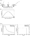
- (a) Heating cycles with lasers illustrating the stabilization cycles in the left (counter body) and right sample holder. (b) Magnified view of the stabilized temperatures in Fig (a),
- Fig. 7
- Thermal profiles attained by heating the samples with lasers. Magnified section showing the scatter in the error precisely,
- Fig. 8
- (a) Time scale showing the time taken for the stabilization of the working and reference sample on the sample holder (right) (b) Magnified view of the stabilized region,
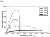
- Fig. 9
- Engineering Stress-Strain diagram of Cu thin films at different temperatures.
-
Fig. 1 shows adevice 1 for the detection of physical properties of samples having twosample holders fig. 1 hasclamps sample support 13, has a symmetrical design with regard to the axis A - A extending between the sample holders. The heat is supplied via the bottom of the device (not shown infig. 1 ). -
Fig. 2 shows aminiature sample support 13. This support may have a size of 1.8×1.8×0.6 cm3 and may be manufactured fromIncoloy® 800 HT, a Nickel super alloy with high thermal conductivity (21.1 W/m°C at 600°C) for quick heat transfer and thermal stabilization. Thesupport 13 comprises twodifferent slots sample holders - It is advantageous to avoid any interfaces such as glue interfaces which may influence the temperature distribution within the device in order to realize the ideal profile as in
Fig. 5b below. Therefore, in a possible embodiment of present invention, a mechanical screw based metallicstrip clamping system use rods 14 having an extremely low thermal conductivity, for example of app. 3 W/mK. An example for a suitable material is Yttria stabilized Zirconia having a thermal conductivity of of 3 W/mK. From the thermal point of view theserods 14 are not visible, they do not have any influence on the temperature of the samples. Aplate 15 is placed at the end of the rods for further restricting the heat transfer from the stage. Theplate 15 may be made from glass ceramic such as Macor®. The device may be attached toholder plates - An additional copper braid (not shown) may be placed behind the rods which is connected to a water cooled copper block. This acts as a heat sink for the whole setup keeping the indenter hardware at cooler temperatures.
- To realize the symmetric profile of the thermal gradients, it is beneficial to have a localized heat source, in particular identical heat sources., for example diode laser systems of spot size 0.4 mm form Dilas Laser systems are suitable to achieve this. The required power required is calculated from cooling curves of heating experiments of the stage conducted with a flame torch. The two stages, one holding the working sample and the mirror sample and the other holding the counter body and the counter body of the mirror sample are heated from the bottom at the center of the stage with two separate laser systems.
- Type K (Chromel/Alumel) thermocouples of 0.25 mm diameter are positioned along the arms of the stage symmetrically on both sides with one placed directly on the surface of the reference sample/tip.
- The two active reference thermocouples (the ones on the reference sample in sample stage and the reference counter body in the counter body stage), and the laser power controls are in turn connected to a Eurotherm controller providing a closed feedback loop to control the designated temperature and power.
- The indenter system is a straining rig with a force and displacement resolutions of 10µm and 1 nm respectively. The whole system is placed in a steel chamber capable of attaining vacuum in the range of 10-5-10-6 mbar. An inverted optical microscope may be used as a visual aid.
-
Fig. 3 shows a cut along line A - A of the device ofFig. 2 having two asample support 1, each with asample holder 2 for the working sample and asample holder 3 for the mirror sample. The sample supports are located within ameasurement chamber 18. The workingsample 2 and themirror sample 3 are situated on the two arms of thedevice 1. The samples are heated with aheating supply 6 and 6' located in centre of the bottom of thedevice 1. The distances to the samples are the same so that the samples are heated evenly to the same temperature. The temperature is measured at various measurement points as shown inFig. 3 . -
Fig. 4 shows a schematic view of the device ofFig. 1 with the temperature measuring points. Themirror sample 3 and the workingsample 2 are placed at an equidistant position from theheating source 6, i.e. the heating source is symmetrically centered between bothsamples heating source 6 heats thesample support 13 and the samples from the bottom and the heat flux towards the ends of the stage will ideally result in a thermal profile demonstrated in theFig. 5b . With astable heat source 3, the temperatures T0, T1, T2 and T3 on the side of the reference sample (measuring points 8, 9, 10, 11 and 12) will be identical to the temperatures T0*, T1*, T2* and T3* (measuring points 8', 9', 10', 11' and 12') on the side of the working sample. At the measuring points suitable thermocouples are arranged in order to measure the temperature at this points. -
Fig. 5 shows also a schematic view of the device offig. 1 with the temperature measuring points (T0, T1, T2 and T3, T0*, t1*, T2* and T3*) inFig. 5a and the ideal thermal profile inFig. 5b . This thermal profile shown inFig. 5b allows the measurement of solely the temperature T0 surface of themirror sample 3. The mirror sample 3 (called reference sample inFig. 5a ) and the workingsample 2 are identical and it is assumed that the temperature of the surface of the working sample T0* is the same as the temperature T0 of the surface of the mirror sample. This is backed by other recorded temperatures along the profile on both sides symmetrically. This guarantees an accurate prediction of the surface temperature of the sample T0* without any thermocouple at the working sample and thereby avoiding any damage to the micron sized features of the sample. - The experiments were carried out with two samples, one working sample and one mirror sample. However, within the scope of present invention also more than one working sample and more than one mirror sample can be used.
- The samples are heated to a temperature of 600°C, the thermal stabilization can be seen the
Fig. 6 . The heating source can be suitable heating source known in the art which can heat the samples to a defined temperature, especially to temperatures above 200°C, preferably for heating the samples a laser is used. The temperature of the reference sample is measured with temperature sensors, in present experiments thermocouples are used. It was found that the feedback loop between the laser power input and the reference thermocouples resulted in heating and thermal stabilization of both the stages in less than 10 minutes. The temperatures of the stages with respect to reference thermocouples are stable and accurate to 0.1 °C (the resolution limit of the thermocouples). - A further important consideration for realizing minimal drifts is the thermal profile in each sample support. This profile is shown in
Fig. 7 which experimentally validates the ideal thermal profile along the sample support. Thus, a temperature measurement of the working sample T0* with an accuracy of ±2.5°C can be achieved by measuring the surface temperature of the reference sample at T0. T0* will not be measured during an actual experiment, but can be estimated from the other temperatures with high precision. - The asymmetry in the thermal profile at the center of the stage araised due to misalignment of the laser to the center only by fractions of millimeter and this is more pronounced at higher temperatures. It can also be seen from the profile in
Fig. 7 that this misalignment did not influence the symmetric profile towards the ends of the stages due to the high thermal conductivity of therods 14. Large differences of the temperatures recorded by the central thermocouples also explain the pronounced errors that can manifest in current day setups where calibrations are used especially at higher temperatures. The stabilization of the whole stage is achieved in 10 minutes and can be seen in theFig. 8 . - The stabilization is defined as the stability of all the thermocouple recordings to 0.1 °C over a period of at least 5 minutes. This in turn means the thermal stabilization at a particular distance on the stage as well as stabilization of heat flow through the stage as well. Constant heat flow in turn provides a stable regulated temperatures all around.
- The performance aspects of the setup can be summarized in the table below.
T in °C (Temperature at the reference thermocouple) ΔT in °C (difference in temperature of thermocouple closest to the heat source and the one on the reference sample/tip t in minutes (time taken to stabilize at this temperature) ΔT |(T0 - T0*)| 100 3.7 10 1.2 200 9.8 10 1.5 300 15.5 10 1.9 400 21.7 10 2.2 500 28.2 10 1.9 600 33.2 10 0.8 - The above described experimental setup is used to mechanically characterize pure Copper (Cu) thin films by producing tensile specimens of 4µm thickness and 23µm gauge width till temperatures of 400°C. The presented Copper tensile samples were prepared through a photolithographic process, in which the geometry of the samples was generated by deposition of material on a photoresist structure. In this process, Copper was deposited by magnetron sputtering from high purity (99.999 at. %) Copper targets. After depositing Copper, the tensile samples were separated by dissolving the underlying photoresist layer.
- From the tensile tests compiled in
Fig. 9 , a reduction in tensile strength with increased elongations to fracture is observed for increasing temperatures. The change in tensile strength is attributed to two main effects caused by the elevated temperature. Firstly an increase in grain size followed by increased dislocation movement. Though the setup can reach testing temperatures of 800°C, Copper thin film samples are tested only till 400°C, due to the limitation of the displacement range of the indenter system used. The current displacement range of 32 µm was not sufficient to reach the fracture, even at 400°C as can be seen inFig. 9 due to the flow properties of pure Copper at higher temperatures. - With the process of present invention it is possible to measure the temperatures directly in micro fracture deformation devices is introduced with a known and definite error of only ±2.5°C at 600°C. Maximum temperatures as high as 800°C can be achieved with this approach in the above described setup with minimal but known errors.
-
- 1
- device for the detection of physical properties of samples
- 2
- sample holder for the working sample
- 3
- sample holder for the mirror sample
- 4
- clamp to hold the working sample
- 5
- clamp to hold the mirror sample
- 6
- heating supply
- 7
- centre of the device
- 8, 8'
- measuring points T0, T0*
- 9, 9'
- measuring points T1, T1*
- 10, 10'
- measuring points T2, T2*
- 11, 11'
- measuring points T3, T3*
- 12, 12'
- measuring points T4, T4*
- 13
- sample support
- 14
- rod
- 15
- plate
- 16, 17
- holder plates
- 18
- walls of measurement chamber
Claims (10)
- Process for the temperature detection of a sample the temperature of which cannot be measured directly in a device for measuring physical parameters other than the temperature using two or more identical samples,
characterized in that- the samples are arranged in the device so that they have the same surrounding,- the samples are heated simultaneously to the same temperature,- the temperature of one of the sample is measured while physical experiments are carried out at the other sample(s). - Process according to claim 1, characterized in that the samples are arranged symmetrically.
- Process according to claim 1 or 2, characterized in that the sample at which the temperature is measured is the mirror sample.
- Process according to any of claims 1 to 3, characterized in that the physical experiments are deformation experiments.
- Device for the detection of physical properties of samples comprising a sample support (13) with at least two sample holders (2, 3), a measurement unit for measuring the temperature (7) of the sample in one sample holders (2) and one or more unit(s) for carrying out physical experiments at the sample in the other sample holder (3), wherein the sample holders are arranged so that they have the same measurement surrounding.
- Device according to claim 5, characterized in that the heating system comprises a laser system.
- Device according to claims 5 or 6, characterized in that the device comprise at least two sample supports (13) with at least two sample holders (2, 3), a measurement unit for measuring the temperature (7) of the sample in one sample holder and one or more unit(s) for carrying out physical experiments.
- Device according to claim 7, wherein the sample supports (13) can be moved in relation to another.
- Device according to claims 5 to 8, characterized in that the sample support(s) (13) are arranged in a chamber (18) being shielded against external influence.
- Device according to claim 9, , characterized in that the chamber (18) is a vacuum chamber.
Priority Applications (2)
| Application Number | Priority Date | Filing Date | Title |
|---|---|---|---|
| ES18199374T ES2937233T3 (en) | 2018-10-09 | 2018-10-09 | Process for temperature measurement in a high temperature microstrain device |
| EP18199374.2A EP3637073B1 (en) | 2018-10-09 | 2018-10-09 | Process for the temperature measurement for a high temperature micro-deformation device |
Applications Claiming Priority (1)
| Application Number | Priority Date | Filing Date | Title |
|---|---|---|---|
| EP18199374.2A EP3637073B1 (en) | 2018-10-09 | 2018-10-09 | Process for the temperature measurement for a high temperature micro-deformation device |
Publications (2)
| Publication Number | Publication Date |
|---|---|
| EP3637073A1 true EP3637073A1 (en) | 2020-04-15 |
| EP3637073B1 EP3637073B1 (en) | 2022-12-21 |
Family
ID=63832221
Family Applications (1)
| Application Number | Title | Priority Date | Filing Date |
|---|---|---|---|
| EP18199374.2A Active EP3637073B1 (en) | 2018-10-09 | 2018-10-09 | Process for the temperature measurement for a high temperature micro-deformation device |
Country Status (2)
| Country | Link |
|---|---|
| EP (1) | EP3637073B1 (en) |
| ES (1) | ES2937233T3 (en) |
Citations (1)
| Publication number | Priority date | Publication date | Assignee | Title |
|---|---|---|---|---|
| GB1422735A (en) * | 1972-04-20 | 1976-01-28 | Commissariat Energie Atomique | Apparatus for carrying out differential thermal analysis |
-
2018
- 2018-10-09 EP EP18199374.2A patent/EP3637073B1/en active Active
- 2018-10-09 ES ES18199374T patent/ES2937233T3/en active Active
Patent Citations (1)
| Publication number | Priority date | Publication date | Assignee | Title |
|---|---|---|---|---|
| GB1422735A (en) * | 1972-04-20 | 1976-01-28 | Commissariat Energie Atomique | Apparatus for carrying out differential thermal analysis |
Non-Patent Citations (4)
| Title |
|---|
| "IEEE Standard Design Tests for High-Voltage (1000 V) Fuses and Accessories;IEEE Std C37.41-2016 (Revision of IEEE Std C37.41-2008)", IEEE STANDARD, IEEE, PISCATAWAY, NJ, USA, 9 December 2016 (2016-12-09), pages 1 - 141, XP068113031 * |
| ARIGELA V G ET AL: "Setup of a microscale high temperature loading rig for micro-fracture mechanics", CONFERENCE : EUROMAT 2017, THESSALONIKI, GREECE. 2017-09-17 - 2017-09-22, ?, GR, 17 September 2017 (2017-09-17), pages 1 - 18, XP009512412 * |
| IWABUCHI A ET AL: "THE DEVELOPMENT OF A VICKERS-TYPE HARDNESS TESTER FOR CRYOGENIC TEMPERATURES DOWN TO 4.2 K", CRYOGENICS, ELSEVIER, KIDLINGTON, GB, vol. 36, no. 2, 1 February 1996 (1996-02-01), pages 75 - 81, XP000552292, ISSN: 0011-2275, DOI: 10.1016/0011-2275(96)83806-9 * |
| SEUNGBAE PARK ET AL: "Temperature dependency of coefficient of hygroscopic swelling of molding compound", ELECTRONIC COMPONENTS AND TECHNOLOGY CONFERENCE, 2009. ECTC 2009. 59TH, IEEE, PISCATAWAY, NJ, USA, 26 May 2009 (2009-05-26), pages 172 - 179, XP031474914, ISBN: 978-1-4244-4475-5 * |
Also Published As
| Publication number | Publication date |
|---|---|
| ES2937233T3 (en) | 2023-03-27 |
| EP3637073B1 (en) | 2022-12-21 |
Similar Documents
| Publication | Publication Date | Title |
|---|---|---|
| US9140612B2 (en) | Measuring seebeck coefficient | |
| James et al. | A review of measurement techniques for the thermal expansion coefficient of metals and alloys at elevated temperatures | |
| US9696270B1 (en) | Thermal conductivity measurement apparatus and related methods | |
| JP6789023B2 (en) | Precise method for detecting thermal expansion | |
| EP3637073B1 (en) | Process for the temperature measurement for a high temperature micro-deformation device | |
| JPH11183413A (en) | Expansion measurement device | |
| Yamada et al. | A calibration method for measuring thermal expansions with a push-rod dilatometer | |
| Fricke et al. | Strain gauge factor and TCR of sputter deposited Pt thin films up to 850 C | |
| Folkman et al. | Characterization of electroless nickel plating on aluminum mirrors | |
| Karanjgaokar et al. | Microscale experiments at elevated temperatures evaluated with digital image correlation | |
| JP2004053252A (en) | Molded parts for precision equipment and method and apparatus for measuring linear expansion coefficient thereof | |
| Harasztosi et al. | Temperature Calibration of Twin Micro-heater Based Microcalorimeter | |
| Yin et al. | Measurement of refractive index of GaP crystal over a large temperature range using interferometry | |
| JP2674684B2 (en) | Thermal expansion coefficient measurement method | |
| Watanabe et al. | Laser interferometric dilatometer applicable to temperature range from 1300 to 2000 K | |
| Arigela et al. | Development of a high-temperature micromechanics stage with a novel temperature measurement approach | |
| JP2007218591A (en) | Hybrid surface thermometer, temperature distribution measuring device and measuring method | |
| Roebuck et al. | Characterisation of Nimonic 90 by the use of miniaturised multiproperty mechanical and physical tests | |
| JPH07248285A (en) | Surface property evaluation device | |
| Hay et al. | A new reference material for high-temperature thermal transport properties--LNE participation in the certification process of Pyroceram 9606. | |
| Kompan et al. | Investigation of thermal expansion of a glass–ceramic material with an extra-low thermal linear expansion coefficient | |
| SU920485A1 (en) | Device for investigating metal and alloy properties | |
| US11333601B1 (en) | Thermo-optic refractometry | |
| Wang et al. | A contactless CCD dilatometer for foil materials | |
| Sham et al. | Surveillance Test Articles Development |
Legal Events
| Date | Code | Title | Description |
|---|---|---|---|
| PUAI | Public reference made under article 153(3) epc to a published international application that has entered the european phase |
Free format text: ORIGINAL CODE: 0009012 |
|
| STAA | Information on the status of an ep patent application or granted ep patent |
Free format text: STATUS: THE APPLICATION HAS BEEN PUBLISHED |
|
| AK | Designated contracting states |
Kind code of ref document: A1 Designated state(s): AL AT BE BG CH CY CZ DE DK EE ES FI FR GB GR HR HU IE IS IT LI LT LU LV MC MK MT NL NO PL PT RO RS SE SI SK SM TR |
|
| AX | Request for extension of the european patent |
Extension state: BA ME |
|
| STAA | Information on the status of an ep patent application or granted ep patent |
Free format text: STATUS: REQUEST FOR EXAMINATION WAS MADE |
|
| 17P | Request for examination filed |
Effective date: 20200930 |
|
| RBV | Designated contracting states (corrected) |
Designated state(s): AL AT BE BG CH CY CZ DE DK EE ES FI FR GB GR HR HU IE IS IT LI LT LU LV MC MK MT NL NO PL PT RO RS SE SI SK SM TR |
|
| STAA | Information on the status of an ep patent application or granted ep patent |
Free format text: STATUS: EXAMINATION IS IN PROGRESS |
|
| 17Q | First examination report despatched |
Effective date: 20210208 |
|
| RIC1 | Information provided on ipc code assigned before grant |
Ipc: G01K 7/42 20060101ALI20220817BHEP Ipc: G01N 3/42 20060101ALI20220817BHEP Ipc: G01K 1/14 20060101AFI20220817BHEP |
|
| GRAP | Despatch of communication of intention to grant a patent |
Free format text: ORIGINAL CODE: EPIDOSNIGR1 |
|
| STAA | Information on the status of an ep patent application or granted ep patent |
Free format text: STATUS: GRANT OF PATENT IS INTENDED |
|
| GRAS | Grant fee paid |
Free format text: ORIGINAL CODE: EPIDOSNIGR3 |
|
| INTG | Intention to grant announced |
Effective date: 20221017 |
|
| RIN1 | Information on inventor provided before grant (corrected) |
Inventor name: KOELLING, MICHAEL Inventor name: ARIGELA, VISWANADH GOWTHAM Inventor name: GONZALEZ, IVAN Inventor name: KIRCHLECHNER, CHRISTOPH |
|
| GRAA | (expected) grant |
Free format text: ORIGINAL CODE: 0009210 |
|
| STAA | Information on the status of an ep patent application or granted ep patent |
Free format text: STATUS: THE PATENT HAS BEEN GRANTED |
|
| AK | Designated contracting states |
Kind code of ref document: B1 Designated state(s): AL AT BE BG CH CY CZ DE DK EE ES FI FR GB GR HR HU IE IS IT LI LT LU LV MC MK MT NL NO PL PT RO RS SE SI SK SM TR |
|
| REG | Reference to a national code |
Ref country code: GB Ref legal event code: FG4D |
|
| REG | Reference to a national code |
Ref country code: CH Ref legal event code: EP |
|
| REG | Reference to a national code |
Ref country code: DE Ref legal event code: R096 Ref document number: 602018044438 Country of ref document: DE |
|
| REG | Reference to a national code |
Ref country code: AT Ref legal event code: REF Ref document number: 1539315 Country of ref document: AT Kind code of ref document: T Effective date: 20230115 |
|
| REG | Reference to a national code |
Ref country code: IE Ref legal event code: FG4D |
|
| REG | Reference to a national code |
Ref country code: ES Ref legal event code: FG2A Ref document number: 2937233 Country of ref document: ES Kind code of ref document: T3 Effective date: 20230327 |
|
| REG | Reference to a national code |
Ref country code: LT Ref legal event code: MG9D |
|
| REG | Reference to a national code |
Ref country code: NL Ref legal event code: MP Effective date: 20221221 |
|
| PG25 | Lapsed in a contracting state [announced via postgrant information from national office to epo] |
Ref country code: SE Free format text: LAPSE BECAUSE OF FAILURE TO SUBMIT A TRANSLATION OF THE DESCRIPTION OR TO PAY THE FEE WITHIN THE PRESCRIBED TIME-LIMIT Effective date: 20221221 Ref country code: NO Free format text: LAPSE BECAUSE OF FAILURE TO SUBMIT A TRANSLATION OF THE DESCRIPTION OR TO PAY THE FEE WITHIN THE PRESCRIBED TIME-LIMIT Effective date: 20230321 Ref country code: LT Free format text: LAPSE BECAUSE OF FAILURE TO SUBMIT A TRANSLATION OF THE DESCRIPTION OR TO PAY THE FEE WITHIN THE PRESCRIBED TIME-LIMIT Effective date: 20221221 Ref country code: FI Free format text: LAPSE BECAUSE OF FAILURE TO SUBMIT A TRANSLATION OF THE DESCRIPTION OR TO PAY THE FEE WITHIN THE PRESCRIBED TIME-LIMIT Effective date: 20221221 |
|
| PG25 | Lapsed in a contracting state [announced via postgrant information from national office to epo] |
Ref country code: RS Free format text: LAPSE BECAUSE OF FAILURE TO SUBMIT A TRANSLATION OF THE DESCRIPTION OR TO PAY THE FEE WITHIN THE PRESCRIBED TIME-LIMIT Effective date: 20221221 Ref country code: LV Free format text: LAPSE BECAUSE OF FAILURE TO SUBMIT A TRANSLATION OF THE DESCRIPTION OR TO PAY THE FEE WITHIN THE PRESCRIBED TIME-LIMIT Effective date: 20221221 Ref country code: HR Free format text: LAPSE BECAUSE OF FAILURE TO SUBMIT A TRANSLATION OF THE DESCRIPTION OR TO PAY THE FEE WITHIN THE PRESCRIBED TIME-LIMIT Effective date: 20221221 Ref country code: GR Free format text: LAPSE BECAUSE OF FAILURE TO SUBMIT A TRANSLATION OF THE DESCRIPTION OR TO PAY THE FEE WITHIN THE PRESCRIBED TIME-LIMIT Effective date: 20230322 |
|
| PG25 | Lapsed in a contracting state [announced via postgrant information from national office to epo] |
Ref country code: NL Free format text: LAPSE BECAUSE OF FAILURE TO SUBMIT A TRANSLATION OF THE DESCRIPTION OR TO PAY THE FEE WITHIN THE PRESCRIBED TIME-LIMIT Effective date: 20221221 |
|
| PG25 | Lapsed in a contracting state [announced via postgrant information from national office to epo] |
Ref country code: SM Free format text: LAPSE BECAUSE OF FAILURE TO SUBMIT A TRANSLATION OF THE DESCRIPTION OR TO PAY THE FEE WITHIN THE PRESCRIBED TIME-LIMIT Effective date: 20221221 Ref country code: RO Free format text: LAPSE BECAUSE OF FAILURE TO SUBMIT A TRANSLATION OF THE DESCRIPTION OR TO PAY THE FEE WITHIN THE PRESCRIBED TIME-LIMIT Effective date: 20221221 Ref country code: PT Free format text: LAPSE BECAUSE OF FAILURE TO SUBMIT A TRANSLATION OF THE DESCRIPTION OR TO PAY THE FEE WITHIN THE PRESCRIBED TIME-LIMIT Effective date: 20230421 Ref country code: EE Free format text: LAPSE BECAUSE OF FAILURE TO SUBMIT A TRANSLATION OF THE DESCRIPTION OR TO PAY THE FEE WITHIN THE PRESCRIBED TIME-LIMIT Effective date: 20221221 Ref country code: CZ Free format text: LAPSE BECAUSE OF FAILURE TO SUBMIT A TRANSLATION OF THE DESCRIPTION OR TO PAY THE FEE WITHIN THE PRESCRIBED TIME-LIMIT Effective date: 20221221 |
|
| PG25 | Lapsed in a contracting state [announced via postgrant information from national office to epo] |
Ref country code: SK Free format text: LAPSE BECAUSE OF FAILURE TO SUBMIT A TRANSLATION OF THE DESCRIPTION OR TO PAY THE FEE WITHIN THE PRESCRIBED TIME-LIMIT Effective date: 20221221 Ref country code: PL Free format text: LAPSE BECAUSE OF FAILURE TO SUBMIT A TRANSLATION OF THE DESCRIPTION OR TO PAY THE FEE WITHIN THE PRESCRIBED TIME-LIMIT Effective date: 20221221 Ref country code: IS Free format text: LAPSE BECAUSE OF FAILURE TO SUBMIT A TRANSLATION OF THE DESCRIPTION OR TO PAY THE FEE WITHIN THE PRESCRIBED TIME-LIMIT Effective date: 20230421 Ref country code: AL Free format text: LAPSE BECAUSE OF FAILURE TO SUBMIT A TRANSLATION OF THE DESCRIPTION OR TO PAY THE FEE WITHIN THE PRESCRIBED TIME-LIMIT Effective date: 20221221 |
|
| REG | Reference to a national code |
Ref country code: DE Ref legal event code: R097 Ref document number: 602018044438 Country of ref document: DE |
|
| PLBE | No opposition filed within time limit |
Free format text: ORIGINAL CODE: 0009261 |
|
| STAA | Information on the status of an ep patent application or granted ep patent |
Free format text: STATUS: NO OPPOSITION FILED WITHIN TIME LIMIT |
|
| PG25 | Lapsed in a contracting state [announced via postgrant information from national office to epo] |
Ref country code: DK Free format text: LAPSE BECAUSE OF FAILURE TO SUBMIT A TRANSLATION OF THE DESCRIPTION OR TO PAY THE FEE WITHIN THE PRESCRIBED TIME-LIMIT Effective date: 20221221 |
|
| 26N | No opposition filed |
Effective date: 20230922 |
|
| REG | Reference to a national code |
Ref country code: AT Ref legal event code: UEP Ref document number: 1539315 Country of ref document: AT Kind code of ref document: T Effective date: 20221221 |
|
| PG25 | Lapsed in a contracting state [announced via postgrant information from national office to epo] |
Ref country code: SI Free format text: LAPSE BECAUSE OF FAILURE TO SUBMIT A TRANSLATION OF THE DESCRIPTION OR TO PAY THE FEE WITHIN THE PRESCRIBED TIME-LIMIT Effective date: 20221221 |
|
| PG25 | Lapsed in a contracting state [announced via postgrant information from national office to epo] |
Ref country code: IT Free format text: LAPSE BECAUSE OF FAILURE TO SUBMIT A TRANSLATION OF THE DESCRIPTION OR TO PAY THE FEE WITHIN THE PRESCRIBED TIME-LIMIT Effective date: 20221221 Ref country code: MC Free format text: LAPSE BECAUSE OF FAILURE TO SUBMIT A TRANSLATION OF THE DESCRIPTION OR TO PAY THE FEE WITHIN THE PRESCRIBED TIME-LIMIT Effective date: 20221221 |
|
| REG | Reference to a national code |
Ref country code: CH Ref legal event code: PL |
|
| REG | Reference to a national code |
Ref country code: BE Ref legal event code: MM Effective date: 20231031 |
|
| PG25 | Lapsed in a contracting state [announced via postgrant information from national office to epo] |
Ref country code: LU Free format text: LAPSE BECAUSE OF NON-PAYMENT OF DUE FEES Effective date: 20231009 |
|
| PG25 | Lapsed in a contracting state [announced via postgrant information from national office to epo] |
Ref country code: LU Free format text: LAPSE BECAUSE OF NON-PAYMENT OF DUE FEES Effective date: 20231009 |
|
| PG25 | Lapsed in a contracting state [announced via postgrant information from national office to epo] |
Ref country code: CH Free format text: LAPSE BECAUSE OF NON-PAYMENT OF DUE FEES Effective date: 20231031 |
|
| PG25 | Lapsed in a contracting state [announced via postgrant information from national office to epo] |
Ref country code: CH Free format text: LAPSE BECAUSE OF NON-PAYMENT OF DUE FEES Effective date: 20231031 |
|
| PG25 | Lapsed in a contracting state [announced via postgrant information from national office to epo] |
Ref country code: BE Free format text: LAPSE BECAUSE OF NON-PAYMENT OF DUE FEES Effective date: 20231031 |
|
| PG25 | Lapsed in a contracting state [announced via postgrant information from national office to epo] |
Ref country code: IE Free format text: LAPSE BECAUSE OF NON-PAYMENT OF DUE FEES Effective date: 20231009 |
|
| PG25 | Lapsed in a contracting state [announced via postgrant information from national office to epo] |
Ref country code: IE Free format text: LAPSE BECAUSE OF NON-PAYMENT OF DUE FEES Effective date: 20231009 |
|
| PG25 | Lapsed in a contracting state [announced via postgrant information from national office to epo] |
Ref country code: BG Free format text: LAPSE BECAUSE OF FAILURE TO SUBMIT A TRANSLATION OF THE DESCRIPTION OR TO PAY THE FEE WITHIN THE PRESCRIBED TIME-LIMIT Effective date: 20221221 |
|
| PG25 | Lapsed in a contracting state [announced via postgrant information from national office to epo] |
Ref country code: BG Free format text: LAPSE BECAUSE OF FAILURE TO SUBMIT A TRANSLATION OF THE DESCRIPTION OR TO PAY THE FEE WITHIN THE PRESCRIBED TIME-LIMIT Effective date: 20221221 |
|
| REG | Reference to a national code |
Ref country code: DE Ref legal event code: R081 Ref document number: 602018044438 Country of ref document: DE Owner name: MAX-PLANCK-INSTITUT FUER NACHHALTIGE MATERIALI, DE Free format text: FORMER OWNER: MAX-PLANCK-INSTITUT FUER EISENFORSCHUNG GMBH, 40237 DUESSELDORF, DE |
|
| PG25 | Lapsed in a contracting state [announced via postgrant information from national office to epo] |
Ref country code: CY Free format text: LAPSE BECAUSE OF FAILURE TO SUBMIT A TRANSLATION OF THE DESCRIPTION OR TO PAY THE FEE WITHIN THE PRESCRIBED TIME-LIMIT; INVALID AB INITIO Effective date: 20181009 |
|
| PG25 | Lapsed in a contracting state [announced via postgrant information from national office to epo] |
Ref country code: HU Free format text: LAPSE BECAUSE OF FAILURE TO SUBMIT A TRANSLATION OF THE DESCRIPTION OR TO PAY THE FEE WITHIN THE PRESCRIBED TIME-LIMIT; INVALID AB INITIO Effective date: 20181009 |
|
| REG | Reference to a national code |
Ref country code: AT Ref legal event code: HC Ref document number: 1539315 Country of ref document: AT Kind code of ref document: T Owner name: MAX-PLANCK-INSTITUT FUER NACHHALTIGE MATERIALIE, DE Effective date: 20250729 |
|
| PG25 | Lapsed in a contracting state [announced via postgrant information from national office to epo] |
Ref country code: TR Free format text: LAPSE BECAUSE OF FAILURE TO SUBMIT A TRANSLATION OF THE DESCRIPTION OR TO PAY THE FEE WITHIN THE PRESCRIBED TIME-LIMIT Effective date: 20221221 |
|
| PGFP | Annual fee paid to national office [announced via postgrant information from national office to epo] |
Ref country code: DE Payment date: 20250930 Year of fee payment: 8 |
|
| PGFP | Annual fee paid to national office [announced via postgrant information from national office to epo] |
Ref country code: GB Payment date: 20251024 Year of fee payment: 8 |
|
| PGFP | Annual fee paid to national office [announced via postgrant information from national office to epo] |
Ref country code: AT Payment date: 20251021 Year of fee payment: 8 |
|
| PGFP | Annual fee paid to national office [announced via postgrant information from national office to epo] |
Ref country code: FR Payment date: 20251027 Year of fee payment: 8 |
|
| PGFP | Annual fee paid to national office [announced via postgrant information from national office to epo] |
Ref country code: ES Payment date: 20251114 Year of fee payment: 8 |
|
| REG | Reference to a national code |
Ref country code: ES Ref legal event code: PC2A Owner name: MAX-PLANCK-INSTITUT FUER NACHHALTIGE MATERIALIEN GMBH Effective date: 20260313 |