EP3636999A1 - Tension fit insulation - Google Patents
Tension fit insulation Download PDFInfo
- Publication number
- EP3636999A1 EP3636999A1 EP19199967.1A EP19199967A EP3636999A1 EP 3636999 A1 EP3636999 A1 EP 3636999A1 EP 19199967 A EP19199967 A EP 19199967A EP 3636999 A1 EP3636999 A1 EP 3636999A1
- Authority
- EP
- European Patent Office
- Prior art keywords
- insulator
- flue
- cut
- opening
- bending portion
- Prior art date
- Legal status (The legal status is an assumption and is not a legal conclusion. Google has not performed a legal analysis and makes no representation as to the accuracy of the status listed.)
- Granted
Links
- 238000009413 insulation Methods 0.000 title claims description 51
- 239000012212 insulator Substances 0.000 claims abstract description 69
- 238000005452 bending Methods 0.000 claims abstract description 34
- 239000011152 fibreglass Substances 0.000 claims description 5
- 238000009434 installation Methods 0.000 claims 1
- 238000000034 method Methods 0.000 description 15
- 206010022000 influenza Diseases 0.000 description 4
- 239000000463 material Substances 0.000 description 3
- 239000000853 adhesive Substances 0.000 description 2
- 230000001070 adhesive effect Effects 0.000 description 2
- 230000008901 benefit Effects 0.000 description 2
- VNWKTOKETHGBQD-UHFFFAOYSA-N methane Chemical compound C VNWKTOKETHGBQD-UHFFFAOYSA-N 0.000 description 2
- 239000000567 combustion gas Substances 0.000 description 1
- 238000002485 combustion reaction Methods 0.000 description 1
- 230000006835 compression Effects 0.000 description 1
- 238000007906 compression Methods 0.000 description 1
- 239000004020 conductor Substances 0.000 description 1
- 238000010411 cooking Methods 0.000 description 1
- 239000003365 glass fiber Substances 0.000 description 1
- 239000012774 insulation material Substances 0.000 description 1
- 239000002557 mineral fiber Substances 0.000 description 1
- 239000003345 natural gas Substances 0.000 description 1
Images



Classifications
-
- F—MECHANICAL ENGINEERING; LIGHTING; HEATING; WEAPONS; BLASTING
- F16—ENGINEERING ELEMENTS AND UNITS; GENERAL MEASURES FOR PRODUCING AND MAINTAINING EFFECTIVE FUNCTIONING OF MACHINES OR INSTALLATIONS; THERMAL INSULATION IN GENERAL
- F16L—PIPES; JOINTS OR FITTINGS FOR PIPES; SUPPORTS FOR PIPES, CABLES OR PROTECTIVE TUBING; MEANS FOR THERMAL INSULATION IN GENERAL
- F16L59/00—Thermal insulation in general
- F16L59/02—Shape or form of insulating materials, with or without coverings integral with the insulating materials
- F16L59/021—Shape or form of insulating materials, with or without coverings integral with the insulating materials comprising a single piece or sleeve, e.g. split sleeves; consisting of two half sleeves; comprising more than two segments
-
- F—MECHANICAL ENGINEERING; LIGHTING; HEATING; WEAPONS; BLASTING
- F16—ENGINEERING ELEMENTS AND UNITS; GENERAL MEASURES FOR PRODUCING AND MAINTAINING EFFECTIVE FUNCTIONING OF MACHINES OR INSTALLATIONS; THERMAL INSULATION IN GENERAL
- F16L—PIPES; JOINTS OR FITTINGS FOR PIPES; SUPPORTS FOR PIPES, CABLES OR PROTECTIVE TUBING; MEANS FOR THERMAL INSULATION IN GENERAL
- F16L59/00—Thermal insulation in general
- F16L59/02—Shape or form of insulating materials, with or without coverings integral with the insulating materials
- F16L59/028—Compositions for or methods of fixing a thermally insulating material
-
- F—MECHANICAL ENGINEERING; LIGHTING; HEATING; WEAPONS; BLASTING
- F23—COMBUSTION APPARATUS; COMBUSTION PROCESSES
- F23J—REMOVAL OR TREATMENT OF COMBUSTION PRODUCTS OR COMBUSTION RESIDUES; FLUES
- F23J13/00—Fittings for chimneys or flues
- F23J13/02—Linings; Jackets; Casings
-
- F—MECHANICAL ENGINEERING; LIGHTING; HEATING; WEAPONS; BLASTING
- F23—COMBUSTION APPARATUS; COMBUSTION PROCESSES
- F23J—REMOVAL OR TREATMENT OF COMBUSTION PRODUCTS OR COMBUSTION RESIDUES; FLUES
- F23J13/00—Fittings for chimneys or flues
- F23J13/04—Joints; Connections
-
- F—MECHANICAL ENGINEERING; LIGHTING; HEATING; WEAPONS; BLASTING
- F24—HEATING; RANGES; VENTILATING
- F24C—DOMESTIC STOVES OR RANGES ; DETAILS OF DOMESTIC STOVES OR RANGES, OF GENERAL APPLICATION
- F24C15/00—Details
- F24C15/20—Removing cooking fumes
-
- F—MECHANICAL ENGINEERING; LIGHTING; HEATING; WEAPONS; BLASTING
- F16—ENGINEERING ELEMENTS AND UNITS; GENERAL MEASURES FOR PRODUCING AND MAINTAINING EFFECTIVE FUNCTIONING OF MACHINES OR INSTALLATIONS; THERMAL INSULATION IN GENERAL
- F16L—PIPES; JOINTS OR FITTINGS FOR PIPES; SUPPORTS FOR PIPES, CABLES OR PROTECTIVE TUBING; MEANS FOR THERMAL INSULATION IN GENERAL
- F16L59/00—Thermal insulation in general
- F16L59/12—Arrangements for supporting insulation from the wall or body insulated, e.g. by means of spacers between pipe and heat-insulating material; Arrangements specially adapted for supporting insulated bodies
-
- F—MECHANICAL ENGINEERING; LIGHTING; HEATING; WEAPONS; BLASTING
- F23—COMBUSTION APPARATUS; COMBUSTION PROCESSES
- F23J—REMOVAL OR TREATMENT OF COMBUSTION PRODUCTS OR COMBUSTION RESIDUES; FLUES
- F23J2213/00—Chimneys or flues
- F23J2213/10—Linings
-
- F—MECHANICAL ENGINEERING; LIGHTING; HEATING; WEAPONS; BLASTING
- F23—COMBUSTION APPARATUS; COMBUSTION PROCESSES
- F23J—REMOVAL OR TREATMENT OF COMBUSTION PRODUCTS OR COMBUSTION RESIDUES; FLUES
- F23J2213/00—Chimneys or flues
- F23J2213/10—Linings
- F23J2213/101—Fastening means therefor
-
- F—MECHANICAL ENGINEERING; LIGHTING; HEATING; WEAPONS; BLASTING
- F23—COMBUSTION APPARATUS; COMBUSTION PROCESSES
- F23J—REMOVAL OR TREATMENT OF COMBUSTION PRODUCTS OR COMBUSTION RESIDUES; FLUES
- F23J2213/00—Chimneys or flues
- F23J2213/40—Heat insulation fittings
-
- Y—GENERAL TAGGING OF NEW TECHNOLOGICAL DEVELOPMENTS; GENERAL TAGGING OF CROSS-SECTIONAL TECHNOLOGIES SPANNING OVER SEVERAL SECTIONS OF THE IPC; TECHNICAL SUBJECTS COVERED BY FORMER USPC CROSS-REFERENCE ART COLLECTIONS [XRACs] AND DIGESTS
- Y10—TECHNICAL SUBJECTS COVERED BY FORMER USPC
- Y10T—TECHNICAL SUBJECTS COVERED BY FORMER US CLASSIFICATION
- Y10T428/00—Stock material or miscellaneous articles
- Y10T428/24—Structurally defined web or sheet [e.g., overall dimension, etc.]
- Y10T428/24273—Structurally defined web or sheet [e.g., overall dimension, etc.] including aperture
- Y10T428/24298—Noncircular aperture [e.g., slit, diamond, rectangular, etc.]
- Y10T428/24314—Slit or elongated
Definitions
- the present application relates generally to insulators for residential appliances, and more specifically to insulators for flues of residential ovens.
- Insulators for residential appliances are known to those skilled in the art. Insulators reduce the transfer of heat or sound between an appliance and the surrounding environment. Thermal insulators used in residential ovens, for example, protect cabinets surrounding the oven.
- FIG. 1 A prior art insulation 100 is shown in Figure 1 .
- the insulator 100 surrounds a flue 102 with a collar of insulation 110 having an opening 112 that the flue 102 fits through.
- the insulation collar 110 can slide up and down on the flue 102 so an adhesive or fastener is required to hold the insulation in place.
- Exemplary embodiments of insulators for flues of residential ovens are disclosed herein.
- An exemplary insulator for a flue of a residential oven includes a bendable insulating body having a first end, a second end, and a bending portion. A first cut is disposed between the bending portion and the first end and a second cut is disposed between the bending portion and the second end. The first cut is expandable to form a first opening and the second cut is expandable to form a second opening.
- Another exemplary insulator for a flue of a residential oven includes a rectangular insulation blanket bendable at a bend location to form a first leg and a second leg.
- the first leg has a first opening and the second leg has a second opening.
- the second opening is substantially aligned with the first opening when the insulator is in a bent condition.
- Still another exemplary embodiment of the present disclosure relates to a method for using an insulator for a flue of a residential oven.
- the method includes providing an insulator comprising a bendable insulating body having a first end, a second end, a bending portion, a first opening disposed between the first end and the bending portion, and a second opening disposed between the second end and the bending portion; bending the insulator along the bending portion; and inserting the flue through the first and second openings.
- the first and second openings are formed by expanding first and second cuts in the bendable insulating body.
- interconnection when one or more components are described as being connected, joined, affixed, coupled, attached, or otherwise interconnected, such interconnection may be direct as between the components or may be indirect such as through the use of one or more intermediary components.
- reference to a "member,” “component,” or “portion” shall not be limited to a single structural member, component, or element but can include an assembly of components, members, or elements.
- the terms “substantially” and “about” are defined as at least close to (and includes) a given value or state (preferably within 10% of, more preferably within 1% of, and most preferably within 0.1% of).
- the insulator 200 protects objects surrounding a flue 202 from the hot gasses flowing through the flue 202.
- the insulator 200 is made from an insulation blanket 210 or any bendable insulation body that is bent at a bend or bending portion 212.
- a first leg 216 of the insulation blanket 210 is formed between the bend 212 and the first end 214 of the blanket 210.
- a second leg 222 of the blanket 210 is formed between the bend 212 and the second end 220.
- a first opening 218 and a second opening 224 are formed in each of the first and second legs 216, 220, respectively.
- the insulation blanket 210 used in the insulation 200 may be formed of glass fibers, mineral fibers, or the like. In some embodiments, the insulation blanket 210 may be about 1 inch to about 3 inches thick. In some embodiments, the insulation 210 may be about 2 inches thick.
- the ends 214, 220 and openings 218, 224 are substantially aligned when the insulation blanket 210 is bent at the bend 212, allowing the flue 202 to be inserted through both openings 218, 224.
- the bent insulation blanket 210 has an inner surface 226 and an outer surface 228.
- the insulator 200 is bent when it is assembled to the flue 202, thereby causing it to elastically deform.
- the elasticity of the material of the blanket 210 causes it to resist the bending force used to bend the insulator, resulting in an elastic force that opposes the bending force.
- No adhesive or fastener is needed to hold the insulator 200 in place on the flue 202 because the elastic force resisting the bending of the insulator 200 causes the insulator to grip the flue 202 at the openings 218, 224.
- FIG. 2B a top view of the insulator 200 is shown.
- the openings 218, 224 position the flue 202 in the insulator 200 so that it is surrounded by the insulation blanket 210 on all sides.
- the size of the insulation blanket 210 and the position of the opening 218 are selected based on the required safety distance between the flue 202 and surrounding objects.
- the hot gasses passing through the flue 202 heat the flue 202 to up to around 700 degrees Fahrenheit. Heat from the flue is prohibited or otherwise retarded by the insulation blanket 210 from flowing into the surrounding surfaces because the insulation blanket 210 is a poor conductor of heat.
- FIG. 2C a side view of the insulator 200 is shown. Bending the insulation blanket 210 generates tensile stress 230 near the outer surface 228 and compression stress 232 near the inner surface 226. Opposing restorative forces (i.e., the elastic force) in the insulation blanket 210 resist the bending, generating straightening forces 234 that oppose the bending of the insulation blanket 210. The straightening forces 234 exerted on each leg 216, 220 of the insulation blanket 210 cause the areas of the insulation near the openings 218, 224 to be pressed against the flue 202 with gripping forces 236.
- the gripping forces 236 cause an increase in friction between the flue 202 and the insulation blanket 210, thereby holding the insulation blanket 210 in place along the flue 202.
- the magnitude of the gripping forces 236 is directed related to the elasticity of the insulation blanket 210.
- the friction between the flue 202 and the insulation blanket 210 is directly related to the magnitude of the gripping forces 236 and the friction coefficient of the materials used for the flue 202 and insulation.
- an exemplary insulator 300 for a flue (not shown) is shown in an unbent condition.
- the insulator 300 is generally rectangular in shape and formed of an insulation blanket 301 similar to the insulation blanket 210 described above.
- the insulator 300 has a first end 302, a second end 304, and a bending portion 306 between the first and second ends 302, 304.
- the bending portion 306 may include relief cuts 308 to reduce the stiffness of the insulation blanket 301 in the area of the bending portion 306.
- Flue opening cuts 310 through the first and second ends 302, 304 allow a flue (not shown) to be inserted through both ends 302, 304 of the insulator 300 when it is in a bent condition.
- a plurality of transverse cuts 312 intersect the opening cuts 310 creating fingers 314 of insulation material that can be compressed to create a flue opening 320 ( Figure 3B ) large enough to fit accept a flue inserted through the insulator 300.
- the fingers 314 expand to contact the flue to provide gripping force in addition to the force supplied by the resistance to the bending of the insulator 300.
- at least one of the fingers 314 is compressed or expanded a different amount than the other fingers 314 to accommodate variations in the size and shape of the flue.
- the fingers 314 compress different amounts to accommodate a flue having a non-rectangular cross-section, such as, for example, an ellipse, a circle, a rounded rectangle, or any other shape suitable for a flue.
- the opening cuts 310 are expanded or stretched open to form the flue opening 320 without the addition of any transverse cuts 312.
Landscapes
- Engineering & Computer Science (AREA)
- General Engineering & Computer Science (AREA)
- Mechanical Engineering (AREA)
- Chemical & Material Sciences (AREA)
- Combustion & Propulsion (AREA)
- Thermal Insulation (AREA)
Abstract
Description
- The present application claims the benefit of
U.S. Provisional Application Serial No. 62/236,298, filed on October 2, 2015 - The present application relates generally to insulators for residential appliances, and more specifically to insulators for flues of residential ovens.
- Insulators for residential appliances are known to those skilled in the art. Insulators reduce the transfer of heat or sound between an appliance and the surrounding environment. Thermal insulators used in residential ovens, for example, protect cabinets surrounding the oven.
- Residential ovens that burn natural gas to heat up the interior of the oven for cooking food require a flue to allow combustion products to be expelled from the oven. The ducts used for oven flues reach very high temperatures and are typically routed through tight spaces that are surrounded by cabinets. These flues can be heated by the combustion gases to around 700 degrees Fahrenheit and are insulated to protect the surrounding surfaces. A
prior art insulation 100 is shown inFigure 1 . Theinsulator 100 surrounds a flue 102 with a collar ofinsulation 110 having anopening 112 that the flue 102 fits through. Theinsulation collar 110 can slide up and down on the flue 102 so an adhesive or fastener is required to hold the insulation in place. - Exemplary embodiments of insulators for flues of residential ovens are disclosed herein.
- An exemplary insulator for a flue of a residential oven includes a bendable insulating body having a first end, a second end, and a bending portion. A first cut is disposed between the bending portion and the first end and a second cut is disposed between the bending portion and the second end. The first cut is expandable to form a first opening and the second cut is expandable to form a second opening.
- Another exemplary insulator for a flue of a residential oven includes a rectangular insulation blanket bendable at a bend location to form a first leg and a second leg. The first leg has a first opening and the second leg has a second opening. The second opening is substantially aligned with the first opening when the insulator is in a bent condition.
- Still another exemplary embodiment of the present disclosure relates to a method for using an insulator for a flue of a residential oven. The method includes providing an insulator comprising a bendable insulating body having a first end, a second end, a bending portion, a first opening disposed between the first end and the bending portion, and a second opening disposed between the second end and the bending portion; bending the insulator along the bending portion; and inserting the flue through the first and second openings. The first and second openings are formed by expanding first and second cuts in the bendable insulating body.
- These and other features and advantages of the present invention will become better understood with regard to the following description and accompanying drawings in which:
-
Figure 1 shows a prior art insulator assembled to a flue; -
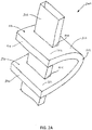
Figure 2A is a perspective view of an exemplary insulation system assembled to a flue; -
Figure 2B is a top view of the exemplary insulation system ofFigure 2A ; -
Figure 2C is a side view of the exemplary insulation system ofFigure 2A ; -
Figure 3A is a plan view of an exemplary insulation blanket before assembly to a flue; and -
Figure 3B is a plan view of the exemplary insulation blanket ofFigure 3A . - Prior to discussing the various embodiments, a review of the definitions of some exemplary terms used throughout the disclosure is appropriate. Both singular and plural forms of all terms fall within each meaning.
- As described herein, when one or more components are described as being connected, joined, affixed, coupled, attached, or otherwise interconnected, such interconnection may be direct as between the components or may be indirect such as through the use of one or more intermediary components. Also as described herein, reference to a "member," "component," or "portion" shall not be limited to a single structural member, component, or element but can include an assembly of components, members, or elements. Also as described herein, the terms "substantially" and "about" are defined as at least close to (and includes) a given value or state (preferably within 10% of, more preferably within 1% of, and most preferably within 0.1% of).
- Referring now to
Figure 2A , anexemplary insulator 200 is shown. Theinsulator 200 protects objects surrounding aflue 202 from the hot gasses flowing through theflue 202. Theinsulator 200 is made from aninsulation blanket 210 or any bendable insulation body that is bent at a bend or bendingportion 212. Afirst leg 216 of theinsulation blanket 210 is formed between thebend 212 and thefirst end 214 of theblanket 210. Asecond leg 222 of theblanket 210 is formed between thebend 212 and thesecond end 220. A first opening 218 and asecond opening 224 are formed in each of the first andsecond legs insulation blanket 210 used in theinsulation 200 may be formed of glass fibers, mineral fibers, or the like. In some embodiments, theinsulation blanket 210 may be about 1 inch to about 3 inches thick. In some embodiments, theinsulation 210 may be about 2 inches thick. - The
ends openings insulation blanket 210 is bent at thebend 212, allowing theflue 202 to be inserted through bothopenings bent insulation blanket 210 has aninner surface 226 and anouter surface 228. Theinsulator 200 is bent when it is assembled to theflue 202, thereby causing it to elastically deform. The elasticity of the material of theblanket 210 causes it to resist the bending force used to bend the insulator, resulting in an elastic force that opposes the bending force. No adhesive or fastener is needed to hold theinsulator 200 in place on theflue 202 because the elastic force resisting the bending of theinsulator 200 causes the insulator to grip theflue 202 at theopenings - Referring now to
Figure 2B , a top view of theinsulator 200 is shown. Theopenings flue 202 in theinsulator 200 so that it is surrounded by theinsulation blanket 210 on all sides. The size of theinsulation blanket 210 and the position of the opening 218 are selected based on the required safety distance between theflue 202 and surrounding objects. The hot gasses passing through theflue 202 heat theflue 202 to up to around 700 degrees Fahrenheit. Heat from the flue is prohibited or otherwise retarded by theinsulation blanket 210 from flowing into the surrounding surfaces because theinsulation blanket 210 is a poor conductor of heat. - Referring now to
Figure 2C , a side view of theinsulator 200 is shown. Bending theinsulation blanket 210 generatestensile stress 230 near theouter surface 228 andcompression stress 232 near theinner surface 226. Opposing restorative forces (i.e., the elastic force) in theinsulation blanket 210 resist the bending, generating straighteningforces 234 that oppose the bending of theinsulation blanket 210. The straighteningforces 234 exerted on eachleg insulation blanket 210 cause the areas of the insulation near theopenings flue 202 with gripping forces 236. The gripping forces 236 cause an increase in friction between theflue 202 and theinsulation blanket 210, thereby holding theinsulation blanket 210 in place along theflue 202. The magnitude of the gripping forces 236 is directed related to the elasticity of theinsulation blanket 210. The friction between theflue 202 and theinsulation blanket 210 is directly related to the magnitude of the gripping forces 236 and the friction coefficient of the materials used for theflue 202 and insulation. - Referring now to
Figures 3A and3B , anexemplary insulator 300 for a flue (not shown) is shown in an unbent condition. Theinsulator 300 is generally rectangular in shape and formed of aninsulation blanket 301 similar to theinsulation blanket 210 described above. Theinsulator 300 has afirst end 302, asecond end 304, and a bendingportion 306 between the first and second ends 302, 304. In some embodiments, the bendingportion 306 may includerelief cuts 308 to reduce the stiffness of theinsulation blanket 301 in the area of the bendingportion 306. - Flue opening cuts 310 through the first and second ends 302, 304 allow a flue (not shown) to be inserted through both ends 302, 304 of the
insulator 300 when it is in a bent condition. A plurality oftransverse cuts 312 intersect the opening cuts 310 creatingfingers 314 of insulation material that can be compressed to create a flue opening 320 (Figure 3B ) large enough to fit accept a flue inserted through theinsulator 300. Thefingers 314 expand to contact the flue to provide gripping force in addition to the force supplied by the resistance to the bending of theinsulator 300. In some embodiments, at least one of thefingers 314 is compressed or expanded a different amount than theother fingers 314 to accommodate variations in the size and shape of the flue. In some embodiments, thefingers 314 compress different amounts to accommodate a flue having a non-rectangular cross-section, such as, for example, an ellipse, a circle, a rounded rectangle, or any other shape suitable for a flue. In some embodiments, the opening cuts 310 are expanded or stretched open to form theflue opening 320 without the addition of anytransverse cuts 312. - While various inventive aspects, concepts and features of the disclosures may be described and illustrated herein as embodied in combination in the exemplary embodiments, these various aspects, concepts, and features may be used in many alternative embodiments, either individually or in various combinations and sub-combinations thereof. Unless expressly excluded herein all such combinations and sub-combinations are intended to be within the scope of the present application. Still further, while various alternative embodiments as to the various aspects, concepts, and features of the disclosures-such as alternative materials, structures, configurations, methods, devices, and components, alternatives as to form, fit, and function, and so on-may be described herein, such descriptions are not intended to be a complete or exhaustive list of available alternative embodiments, whether presently known or later developed. Those skilled in the art may readily adopt one or more of the inventive aspects, concepts, or features into additional embodiments and uses within the scope of the present application even if such embodiments are not expressly disclosed herein. Additionally, even though some features, concepts, or aspects of the disclosures may be described herein as being a preferred arrangement or method, such description is not intended to suggest that such feature is required or necessary unless expressly so stated. Still further, exemplary or representative values and ranges may be included to assist in understanding the present application, however, such values and ranges are not to be construed in a limiting sense and are intended to be critical values or ranges only if so expressly stated. Moreover, while various aspects, features and concepts may be expressly identified herein as being inventive or forming part of a disclosure, such identification is not intended to be exclusive, but rather there may be inventive aspects, concepts, and features that are fully described herein without being expressly identified as such or as part of a specific disclosure, the disclosures instead being set forth in the appended claims. Descriptions of exemplary methods or processes are not limited to inclusion of all steps as being required in all cases, nor is the order that the steps are presented to be construed as required or necessary unless expressly so stated. The words used in the claims have their full ordinary meanings and are not limited in any way by the description of the embodiments in the specification.
- Various preferred features and embodiments of the present invention will now be described with reference to the following numbered paragraphs (paras).
- 1. An insulator for a flue of a residential oven, the insulator comprising:
- a bendable insulating body having a first end, a second end, and a bending portion;
- a first cut disposed between the bending portion and the first end; and
- a second cut disposed between the bending portion and the second end;
- wherein the first cut is expandable to form a first opening; and
- wherein the second cut is expandable to form a second opening.
- 2. The insulator of para 1, wherein the bendable insulating body is a rectangular prism.
- 3. The insulator of para 1, wherein the bendable insulation body is formed of fiberglass.
- 4. The insulator of para 1, wherein the first and second openings are substantially aligned when the bendable insulating body is in a bent condition.
- 5. The insulator of para 1, wherein the bendable insulating body has a thickness in a range of about 1 inch to about 3 inches.
- 6. The insulator of para 1, wherein the bendable insulation body has a thickness of about 2 inches.
- 7. The insulator of para 1, further comprising a first plurality of transverse cuts across the first cut and a second plurality of transverse cuts across the second cut.
- 8. An insulator for a flue of a residential oven, the insulator comprising:
- a rectangular insulation blanket that is bendable at a bend location to form a first leg and a second leg;
- a first opening in the first leg; and
- a second opening in the second leg that is substantially aligned with the first opening in the first leg when the insulator is bent at the bend location.
- 9. The insulator of para 8, wherein the rectangular insulation blanket is formed of fiberglass.
- 10. The insulator of para 8, wherein the rectangular insulation blanket has a thickness in a range of about 1 inch to about 3 inches.
- 11. The insulator of para 8, wherein the rectangular insulation blanket has a thickness of about 2 inches.
- 12. The insulator of para 8, wherein:
- the first opening is formed by a first cut and a first plurality of transverse cuts across the first cut; and
- the second opening is formed by a second cut and a second plurality of transverse cuts across the second cut.
- 13. A method of assembling an insulator to a flue of a residential oven, the method comprising:
- providing an insulator comprising:
- a bendable insulating body having a first end, a second end, and a bending portion;
- a first cut disposed between the bending portion and the first end; and
- a second cut disposed between the bending portion and the second end;
- wherein the first cut is expandable to form a first opening; and
- wherein the second cut is expandable to form a second opening;
- bending the insulator along the bending portion; and
- inserting the flue through the first and second openings.
- providing an insulator comprising:
- 14. The method of para 13, wherein the bendable insulating body is a rectangular prism.
- 15. The method of para 13, wherein the bendable insulating body is a rectangular insulation blanket.
- 16. The method of para 13, wherein the bendable insulating body is formed of fiberglass.
- 17. The method of para 13, wherein the first and second openings are substantially aligned when the bendable insulating body is in a bent condition.
- 18. The method of para 13, wherein the bendable insulating body has a thickness in a range of about 1 inch to about 3 inches.
- 19. The method of para 13, wherein the bendable insulation body has a thickness of about 2 inches.
- 20. The method of para 13, wherein the insulator comprises a first plurality of transverse cuts across the first cut and a second plurality of transverse cuts across the second cut.
Claims (12)
- An insulator (200) for a flue (202) of a residential oven, the insulator (200) comprising:a bendable insulating body (210) having a first end (214), a second end (220), and a bending portion (212);a first cut disposed between the bending portion (212) and the first end (214), the first cut being expandable to form a first opening (218) for receiving a flue (202); anda second cut disposed between the bending portion (212) and the second end (220), the second cut being expandable to form a second opening (224) for receiving the flue (202);wherein the bending portion (212) is configured to be situated on a first side of the flue (202) and the first and second ends (214, 220) are configured to be situated on a second side of the flue (202), upon installation of the insulator (200) on the flue (202).
- The insulator of claim 1, wherein the bendable insulating body is a rectangular prism.
- The insulator of claim 1, wherein the bendable insulation body is formed of fiberglass.
- The insulator of claim 1, wherein the first and second openings are substantially aligned when the bendable insulating body is in a bent condition.
- The insulator of claim 1, wherein the bendable insulating body has a thickness in a range of about 2.54 cm to 7.62 cm (1 inch to about 3 inches).
- The insulator of claim 1, wherein the bendable insulating body has a thickness of about 5.08 cm (2 inches).
- The insulator of claim 1, further comprising a first plurality of transverse cuts across the first cut and a second plurality of transverse cuts across the second cut.
- An insulator (300) for a flue of a residential oven, the insulator (300) comprising:a rectangular insulation blanket (301) that is bendable at a bend location (306) to form a first leg (302) and a second leg (304);a first opening (320) in the first leg (302);a second opening (320) in the second leg (304) that is substantially aligned with the first opening (320) in the first leg (302) when the insulator (300) is bent at the bend location (306); andthe insulator (300) being operable to receive the flue through both of the first and second openings (320) when the insulator (300) is bent at the bend location (306).
- The insulator of claim 8, wherein the rectangular insulation blanket is formed of fiberglass.
- The insulator of claim 8, wherein the rectangular insulation blanket has a thickness in a range of about 2.54 cm to 7.62 cm (1 inch to about 3 inches).
- The insulator of claim 8, wherein the rectangular insulation blanket has a thickness of about 5.08 cm (2 inches).
- The insulator of claim 8, wherein:the first opening is formed by a first cut and a first plurality of transverse cuts across the first cut; andthe second opening is formed by a second cut and a second plurality of transverse cuts across the second cut.
Priority Applications (2)
| Application Number | Priority Date | Filing Date | Title |
|---|---|---|---|
| SI201631354T SI3636999T1 (en) | 2015-10-02 | 2016-09-30 | Tension fit insulation |
| PL19199967T PL3636999T3 (en) | 2015-10-02 | 2016-09-30 | Tension fit insulation |
Applications Claiming Priority (2)
| Application Number | Priority Date | Filing Date | Title |
|---|---|---|---|
| US201562236298P | 2015-10-02 | 2015-10-02 | |
| EP16191826.3A EP3150915A1 (en) | 2015-10-02 | 2016-09-30 | Tension fit insulation |
Related Parent Applications (1)
| Application Number | Title | Priority Date | Filing Date |
|---|---|---|---|
| EP16191826.3A Division EP3150915A1 (en) | 2015-10-02 | 2016-09-30 | Tension fit insulation |
Publications (2)
| Publication Number | Publication Date |
|---|---|
| EP3636999A1 true EP3636999A1 (en) | 2020-04-15 |
| EP3636999B1 EP3636999B1 (en) | 2021-08-25 |
Family
ID=57042847
Family Applications (2)
| Application Number | Title | Priority Date | Filing Date |
|---|---|---|---|
| EP16191826.3A Withdrawn EP3150915A1 (en) | 2015-10-02 | 2016-09-30 | Tension fit insulation |
| EP19199967.1A Active EP3636999B1 (en) | 2015-10-02 | 2016-09-30 | Tension fit insulation |
Family Applications Before (1)
| Application Number | Title | Priority Date | Filing Date |
|---|---|---|---|
| EP16191826.3A Withdrawn EP3150915A1 (en) | 2015-10-02 | 2016-09-30 | Tension fit insulation |
Country Status (5)
| Country | Link |
|---|---|
| US (2) | US10422464B2 (en) |
| EP (2) | EP3150915A1 (en) |
| ES (1) | ES2894893T3 (en) |
| PL (1) | PL3636999T3 (en) |
| SI (1) | SI3636999T1 (en) |
Citations (7)
| Publication number | Priority date | Publication date | Assignee | Title |
|---|---|---|---|---|
| GB1137121A (en) * | 1964-10-21 | 1968-12-18 | Lo Dense Fixings Rugby Ltd | Improvements in and in the manufacture of insulated ducting, tubing or casing |
| US3825465A (en) * | 1972-03-24 | 1974-07-23 | R Stock | Three dimensional reticulated structure |
| FR2383587A7 (en) * | 1977-03-11 | 1978-10-06 | Viessmann Hans | Thermal insulation jacket for central heating boiler - has end panels supported by metal frames and cut to accommodate pipes, with slots closed by clamps to block air gaps |
| DE19509892A1 (en) * | 1995-03-17 | 1996-09-19 | Gruenzweig & Hartmann | Damper for three-shell ventilated chimney |
| EP1020678A1 (en) * | 1999-01-12 | 2000-07-19 | L'air Liquide, Societe Anonyme Pour L'etude Et L'exploitation Des Procedes Georges Claude | Cryogenic fluid transfer line and its use for the transfer of liquid helium |
| US20130022783A1 (en) * | 2011-07-18 | 2013-01-24 | Rilco Manufacturing Company, Inc. | Method and System for Reinforced Pipe Insulation |
| GB2515332A (en) * | 2013-06-20 | 2014-12-24 | Firemac Ltd | Improvements in or relating to fire safety |
Family Cites Families (3)
| Publication number | Priority date | Publication date | Assignee | Title |
|---|---|---|---|---|
| US4039098A (en) * | 1976-01-05 | 1977-08-02 | Kenneth Morris Stilts | Thermal insulation jacket for water heaters |
| WO2013003705A1 (en) * | 2011-06-30 | 2013-01-03 | Abbott Point Of Care Inc. | Methods and devices for determining sensing device usability |
| KR101365657B1 (en) * | 2012-08-07 | 2014-02-24 | 주식회사 경동원 | Low Density Insulation of Inorganic Powder with Supporting Structure Using Expended Perlite, its Manufacturing Method and Making Machine |
-
2016
- 2016-09-29 US US15/279,770 patent/US10422464B2/en active Active
- 2016-09-30 SI SI201631354T patent/SI3636999T1/en unknown
- 2016-09-30 PL PL19199967T patent/PL3636999T3/en unknown
- 2016-09-30 EP EP16191826.3A patent/EP3150915A1/en not_active Withdrawn
- 2016-09-30 EP EP19199967.1A patent/EP3636999B1/en active Active
- 2016-09-30 ES ES19199967T patent/ES2894893T3/en active Active
-
2019
- 2019-06-25 US US16/451,222 patent/US11215311B2/en active Active
Patent Citations (7)
| Publication number | Priority date | Publication date | Assignee | Title |
|---|---|---|---|---|
| GB1137121A (en) * | 1964-10-21 | 1968-12-18 | Lo Dense Fixings Rugby Ltd | Improvements in and in the manufacture of insulated ducting, tubing or casing |
| US3825465A (en) * | 1972-03-24 | 1974-07-23 | R Stock | Three dimensional reticulated structure |
| FR2383587A7 (en) * | 1977-03-11 | 1978-10-06 | Viessmann Hans | Thermal insulation jacket for central heating boiler - has end panels supported by metal frames and cut to accommodate pipes, with slots closed by clamps to block air gaps |
| DE19509892A1 (en) * | 1995-03-17 | 1996-09-19 | Gruenzweig & Hartmann | Damper for three-shell ventilated chimney |
| EP1020678A1 (en) * | 1999-01-12 | 2000-07-19 | L'air Liquide, Societe Anonyme Pour L'etude Et L'exploitation Des Procedes Georges Claude | Cryogenic fluid transfer line and its use for the transfer of liquid helium |
| US20130022783A1 (en) * | 2011-07-18 | 2013-01-24 | Rilco Manufacturing Company, Inc. | Method and System for Reinforced Pipe Insulation |
| GB2515332A (en) * | 2013-06-20 | 2014-12-24 | Firemac Ltd | Improvements in or relating to fire safety |
Also Published As
| Publication number | Publication date |
|---|---|
| US11215311B2 (en) | 2022-01-04 |
| ES2894893T3 (en) | 2022-02-16 |
| US10422464B2 (en) | 2019-09-24 |
| PL3636999T3 (en) | 2022-01-17 |
| EP3150915A1 (en) | 2017-04-05 |
| SI3636999T1 (en) | 2022-01-31 |
| EP3636999B1 (en) | 2021-08-25 |
| US20170097115A1 (en) | 2017-04-06 |
| US20190309890A1 (en) | 2019-10-10 |
Similar Documents
| Publication | Publication Date | Title |
|---|---|---|
| AU753584B2 (en) | An extendible, coilable member | |
| US4314144A (en) | Thermostat mounting arrangement for electric heating appliance | |
| US4346277A (en) | Packaged electrical heating element | |
| KR102482685B1 (en) | Thermal sleeve with self-adjusting positioning member, assembly thereof and method for protecting temperature sensitive member therewith | |
| US20120110823A1 (en) | Smooth linear separation device between a first part and a second part | |
| EP2519765A1 (en) | Solar panel tube | |
| GB0609729D0 (en) | Material and heating cable | |
| US11215311B2 (en) | Tension fit insulation | |
| US10723064B2 (en) | Device and methods for armoring heat shrink kits for impact and flammability protection | |
| WO2009013493A1 (en) | Fixing | |
| US11614183B2 (en) | Insulated hose arrangements | |
| US9989189B1 (en) | Straps for pipe insulation | |
| US5015987A (en) | Temperature sensing apparatus | |
| GB2475269A (en) | Double skin panel for use in HVAC plenums and enclosures | |
| EP1429076A2 (en) | Blow-off vents | |
| US20240110645A1 (en) | A fire collar | |
| WO2020153684A3 (en) | Heating element having fuse function and heater unit comprising same | |
| JP6977230B2 (en) | Piping heating device | |
| AU2013203541A1 (en) | Thermally insulated hot gas piping system | |
| KR101442563B1 (en) | Insulation sheet for pipe | |
| KR200455591Y1 (en) | Pipe cover | |
| US20060196866A1 (en) | Device for keeping heating wires in position in a horizontal oven | |
| KR101373634B1 (en) | Ceramic heater possible windingness | |
| KR20150008589A (en) | Warm member fixed device for duct and fixing mrthod of warm member use it | |
| Kutis et al. | Electro-thermo-mechanical analysis of SMA actuator |
Legal Events
| Date | Code | Title | Description |
|---|---|---|---|
| PUAI | Public reference made under article 153(3) epc to a published international application that has entered the european phase |
Free format text: ORIGINAL CODE: 0009012 |
|
| STAA | Information on the status of an ep patent application or granted ep patent |
Free format text: STATUS: THE APPLICATION HAS BEEN PUBLISHED |
|
| AC | Divisional application: reference to earlier application |
Ref document number: 3150915 Country of ref document: EP Kind code of ref document: P |
|
| AK | Designated contracting states |
Kind code of ref document: A1 Designated state(s): AL AT BE BG CH CY CZ DE DK EE ES FI FR GB GR HR HU IE IS IT LI LT LU LV MC MK MT NL NO PL PT RO RS SE SI SK SM TR |
|
| STAA | Information on the status of an ep patent application or granted ep patent |
Free format text: STATUS: REQUEST FOR EXAMINATION WAS MADE |
|
| 17P | Request for examination filed |
Effective date: 20200929 |
|
| RBV | Designated contracting states (corrected) |
Designated state(s): AL AT BE BG CH CY CZ DE DK EE ES FI FR GB GR HR HU IE IS IT LI LT LU LV MC MK MT NL NO PL PT RO RS SE SI SK SM TR |
|
| GRAP | Despatch of communication of intention to grant a patent |
Free format text: ORIGINAL CODE: EPIDOSNIGR1 |
|
| STAA | Information on the status of an ep patent application or granted ep patent |
Free format text: STATUS: GRANT OF PATENT IS INTENDED |
|
| INTG | Intention to grant announced |
Effective date: 20210326 |
|
| RIN1 | Information on inventor provided before grant (corrected) |
Inventor name: SEWARD, JASON M. |
|
| GRAS | Grant fee paid |
Free format text: ORIGINAL CODE: EPIDOSNIGR3 |
|
| GRAA | (expected) grant |
Free format text: ORIGINAL CODE: 0009210 |
|
| STAA | Information on the status of an ep patent application or granted ep patent |
Free format text: STATUS: THE PATENT HAS BEEN GRANTED |
|
| AC | Divisional application: reference to earlier application |
Ref document number: 3150915 Country of ref document: EP Kind code of ref document: P |
|
| AK | Designated contracting states |
Kind code of ref document: B1 Designated state(s): AL AT BE BG CH CY CZ DE DK EE ES FI FR GB GR HR HU IE IS IT LI LT LU LV MC MK MT NL NO PL PT RO RS SE SI SK SM TR |
|
| REG | Reference to a national code |
Ref country code: CH Ref legal event code: EP |
|
| REG | Reference to a national code |
Ref country code: IE Ref legal event code: FG4D Ref country code: AT Ref legal event code: REF Ref document number: 1424168 Country of ref document: AT Kind code of ref document: T Effective date: 20210915 |
|
| REG | Reference to a national code |
Ref country code: DE Ref legal event code: R096 Ref document number: 602016062939 Country of ref document: DE |
|
| REG | Reference to a national code |
Ref country code: SE Ref legal event code: TRGR |
|
| REG | Reference to a national code |
Ref country code: LT Ref legal event code: MG9D |
|
| REG | Reference to a national code |
Ref country code: NL Ref legal event code: MP Effective date: 20210825 |
|
| PG25 | Lapsed in a contracting state [announced via postgrant information from national office to epo] |
Ref country code: PT Free format text: LAPSE BECAUSE OF FAILURE TO SUBMIT A TRANSLATION OF THE DESCRIPTION OR TO PAY THE FEE WITHIN THE PRESCRIBED TIME-LIMIT Effective date: 20211227 Ref country code: NO Free format text: LAPSE BECAUSE OF FAILURE TO SUBMIT A TRANSLATION OF THE DESCRIPTION OR TO PAY THE FEE WITHIN THE PRESCRIBED TIME-LIMIT Effective date: 20211125 Ref country code: HR Free format text: LAPSE BECAUSE OF FAILURE TO SUBMIT A TRANSLATION OF THE DESCRIPTION OR TO PAY THE FEE WITHIN THE PRESCRIBED TIME-LIMIT Effective date: 20210825 Ref country code: BG Free format text: LAPSE BECAUSE OF FAILURE TO SUBMIT A TRANSLATION OF THE DESCRIPTION OR TO PAY THE FEE WITHIN THE PRESCRIBED TIME-LIMIT Effective date: 20211125 Ref country code: LT Free format text: LAPSE BECAUSE OF FAILURE TO SUBMIT A TRANSLATION OF THE DESCRIPTION OR TO PAY THE FEE WITHIN THE PRESCRIBED TIME-LIMIT Effective date: 20210825 Ref country code: RS Free format text: LAPSE BECAUSE OF FAILURE TO SUBMIT A TRANSLATION OF THE DESCRIPTION OR TO PAY THE FEE WITHIN THE PRESCRIBED TIME-LIMIT Effective date: 20210825 Ref country code: FI Free format text: LAPSE BECAUSE OF FAILURE TO SUBMIT A TRANSLATION OF THE DESCRIPTION OR TO PAY THE FEE WITHIN THE PRESCRIBED TIME-LIMIT Effective date: 20210825 |
|
| REG | Reference to a national code |
Ref country code: ES Ref legal event code: FG2A Ref document number: 2894893 Country of ref document: ES Kind code of ref document: T3 Effective date: 20220216 |
|
| PG25 | Lapsed in a contracting state [announced via postgrant information from national office to epo] |
Ref country code: LV Free format text: LAPSE BECAUSE OF FAILURE TO SUBMIT A TRANSLATION OF THE DESCRIPTION OR TO PAY THE FEE WITHIN THE PRESCRIBED TIME-LIMIT Effective date: 20210825 Ref country code: GR Free format text: LAPSE BECAUSE OF FAILURE TO SUBMIT A TRANSLATION OF THE DESCRIPTION OR TO PAY THE FEE WITHIN THE PRESCRIBED TIME-LIMIT Effective date: 20211126 |
|
| REG | Reference to a national code |
Ref country code: AT Ref legal event code: UEP Ref document number: 1424168 Country of ref document: AT Kind code of ref document: T Effective date: 20210825 |
|
| PG25 | Lapsed in a contracting state [announced via postgrant information from national office to epo] |
Ref country code: NL Free format text: LAPSE BECAUSE OF FAILURE TO SUBMIT A TRANSLATION OF THE DESCRIPTION OR TO PAY THE FEE WITHIN THE PRESCRIBED TIME-LIMIT Effective date: 20210825 |
|
| PG25 | Lapsed in a contracting state [announced via postgrant information from national office to epo] |
Ref country code: DK Free format text: LAPSE BECAUSE OF FAILURE TO SUBMIT A TRANSLATION OF THE DESCRIPTION OR TO PAY THE FEE WITHIN THE PRESCRIBED TIME-LIMIT Effective date: 20210825 |
|
| REG | Reference to a national code |
Ref country code: CH Ref legal event code: PL |
|
| REG | Reference to a national code |
Ref country code: DE Ref legal event code: R097 Ref document number: 602016062939 Country of ref document: DE |
|
| PG25 | Lapsed in a contracting state [announced via postgrant information from national office to epo] |
Ref country code: SM Free format text: LAPSE BECAUSE OF FAILURE TO SUBMIT A TRANSLATION OF THE DESCRIPTION OR TO PAY THE FEE WITHIN THE PRESCRIBED TIME-LIMIT Effective date: 20210825 Ref country code: SK Free format text: LAPSE BECAUSE OF FAILURE TO SUBMIT A TRANSLATION OF THE DESCRIPTION OR TO PAY THE FEE WITHIN THE PRESCRIBED TIME-LIMIT Effective date: 20210825 Ref country code: RO Free format text: LAPSE BECAUSE OF FAILURE TO SUBMIT A TRANSLATION OF THE DESCRIPTION OR TO PAY THE FEE WITHIN THE PRESCRIBED TIME-LIMIT Effective date: 20210825 Ref country code: MC Free format text: LAPSE BECAUSE OF FAILURE TO SUBMIT A TRANSLATION OF THE DESCRIPTION OR TO PAY THE FEE WITHIN THE PRESCRIBED TIME-LIMIT Effective date: 20210825 Ref country code: EE Free format text: LAPSE BECAUSE OF FAILURE TO SUBMIT A TRANSLATION OF THE DESCRIPTION OR TO PAY THE FEE WITHIN THE PRESCRIBED TIME-LIMIT Effective date: 20210825 Ref country code: CZ Free format text: LAPSE BECAUSE OF FAILURE TO SUBMIT A TRANSLATION OF THE DESCRIPTION OR TO PAY THE FEE WITHIN THE PRESCRIBED TIME-LIMIT Effective date: 20210825 Ref country code: AL Free format text: LAPSE BECAUSE OF FAILURE TO SUBMIT A TRANSLATION OF THE DESCRIPTION OR TO PAY THE FEE WITHIN THE PRESCRIBED TIME-LIMIT Effective date: 20210825 |
|
| PLBE | No opposition filed within time limit |
Free format text: ORIGINAL CODE: 0009261 |
|
| STAA | Information on the status of an ep patent application or granted ep patent |
Free format text: STATUS: NO OPPOSITION FILED WITHIN TIME LIMIT |
|
| PG25 | Lapsed in a contracting state [announced via postgrant information from national office to epo] |
Ref country code: LU Free format text: LAPSE BECAUSE OF NON-PAYMENT OF DUE FEES Effective date: 20210930 Ref country code: IE Free format text: LAPSE BECAUSE OF NON-PAYMENT OF DUE FEES Effective date: 20210930 |
|
| 26N | No opposition filed |
Effective date: 20220527 |
|
| PG25 | Lapsed in a contracting state [announced via postgrant information from national office to epo] |
Ref country code: LI Free format text: LAPSE BECAUSE OF NON-PAYMENT OF DUE FEES Effective date: 20210930 Ref country code: CH Free format text: LAPSE BECAUSE OF NON-PAYMENT OF DUE FEES Effective date: 20210930 |
|
| PGFP | Annual fee paid to national office [announced via postgrant information from national office to epo] |
Ref country code: TR Payment date: 20220912 Year of fee payment: 7 Ref country code: SE Payment date: 20220927 Year of fee payment: 7 Ref country code: GB Payment date: 20220927 Year of fee payment: 7 Ref country code: DE Payment date: 20220928 Year of fee payment: 7 Ref country code: AT Payment date: 20220901 Year of fee payment: 7 |
|
| PGFP | Annual fee paid to national office [announced via postgrant information from national office to epo] |
Ref country code: SI Payment date: 20220901 Year of fee payment: 7 Ref country code: PL Payment date: 20220902 Year of fee payment: 7 Ref country code: FR Payment date: 20220926 Year of fee payment: 7 Ref country code: BE Payment date: 20220927 Year of fee payment: 7 |
|
| PGFP | Annual fee paid to national office [announced via postgrant information from national office to epo] |
Ref country code: IT Payment date: 20220926 Year of fee payment: 7 Ref country code: ES Payment date: 20221003 Year of fee payment: 7 |
|
| PG25 | Lapsed in a contracting state [announced via postgrant information from national office to epo] |
Ref country code: CY Free format text: LAPSE BECAUSE OF FAILURE TO SUBMIT A TRANSLATION OF THE DESCRIPTION OR TO PAY THE FEE WITHIN THE PRESCRIBED TIME-LIMIT Effective date: 20210825 |
|
| PG25 | Lapsed in a contracting state [announced via postgrant information from national office to epo] |
Ref country code: HU Free format text: LAPSE BECAUSE OF FAILURE TO SUBMIT A TRANSLATION OF THE DESCRIPTION OR TO PAY THE FEE WITHIN THE PRESCRIBED TIME-LIMIT; INVALID AB INITIO Effective date: 20160930 |
|
| REG | Reference to a national code |
Ref country code: DE Ref legal event code: R119 Ref document number: 602016062939 Country of ref document: DE |
|
| PG25 | Lapsed in a contracting state [announced via postgrant information from national office to epo] |
Ref country code: MK Free format text: LAPSE BECAUSE OF FAILURE TO SUBMIT A TRANSLATION OF THE DESCRIPTION OR TO PAY THE FEE WITHIN THE PRESCRIBED TIME-LIMIT Effective date: 20210825 |
|
| REG | Reference to a national code |
Ref country code: AT Ref legal event code: MM01 Ref document number: 1424168 Country of ref document: AT Kind code of ref document: T Effective date: 20230930 |
|
| REG | Reference to a national code |
Ref country code: BE Ref legal event code: MM Effective date: 20230930 |
|
| REG | Reference to a national code |
Ref country code: SE Ref legal event code: EUG |
|
| GBPC | Gb: european patent ceased through non-payment of renewal fee |
Effective date: 20230930 |
|
| PG25 | Lapsed in a contracting state [announced via postgrant information from national office to epo] |
Ref country code: GB Free format text: LAPSE BECAUSE OF NON-PAYMENT OF DUE FEES Effective date: 20230930 |
|
| PG25 | Lapsed in a contracting state [announced via postgrant information from national office to epo] |
Ref country code: AT Free format text: LAPSE BECAUSE OF NON-PAYMENT OF DUE FEES Effective date: 20230930 |
|
| PG25 | Lapsed in a contracting state [announced via postgrant information from national office to epo] |
Ref country code: GB Free format text: LAPSE BECAUSE OF NON-PAYMENT OF DUE FEES Effective date: 20230930 Ref country code: FR Free format text: LAPSE BECAUSE OF NON-PAYMENT OF DUE FEES Effective date: 20230930 Ref country code: DE Free format text: LAPSE BECAUSE OF NON-PAYMENT OF DUE FEES Effective date: 20240403 Ref country code: AT Free format text: LAPSE BECAUSE OF NON-PAYMENT OF DUE FEES Effective date: 20230930 Ref country code: SI Free format text: LAPSE BECAUSE OF NON-PAYMENT OF DUE FEES Effective date: 20231001 |
|
| PG25 | Lapsed in a contracting state [announced via postgrant information from national office to epo] |
Ref country code: SE Free format text: LAPSE BECAUSE OF NON-PAYMENT OF DUE FEES Effective date: 20231001 Ref country code: BE Free format text: LAPSE BECAUSE OF NON-PAYMENT OF DUE FEES Effective date: 20230930 |
|
| REG | Reference to a national code |
Ref country code: SI Ref legal event code: KO00 Effective date: 20240717 |
|
| PG25 | Lapsed in a contracting state [announced via postgrant information from national office to epo] |
Ref country code: MT Free format text: LAPSE BECAUSE OF FAILURE TO SUBMIT A TRANSLATION OF THE DESCRIPTION OR TO PAY THE FEE WITHIN THE PRESCRIBED TIME-LIMIT Effective date: 20210825 |
|
| REG | Reference to a national code |
Ref country code: ES Ref legal event code: FD2A Effective date: 20241107 |
|
| PG25 | Lapsed in a contracting state [announced via postgrant information from national office to epo] |
Ref country code: IT Free format text: LAPSE BECAUSE OF NON-PAYMENT OF DUE FEES Effective date: 20230930 |
|
| PG25 | Lapsed in a contracting state [announced via postgrant information from national office to epo] |
Ref country code: IT Free format text: LAPSE BECAUSE OF NON-PAYMENT OF DUE FEES Effective date: 20230930 |
|
| PG25 | Lapsed in a contracting state [announced via postgrant information from national office to epo] |
Ref country code: ES Free format text: LAPSE BECAUSE OF NON-PAYMENT OF DUE FEES Effective date: 20231001 |
|
| PG25 | Lapsed in a contracting state [announced via postgrant information from national office to epo] |
Ref country code: ES Free format text: LAPSE BECAUSE OF NON-PAYMENT OF DUE FEES Effective date: 20231001 |
|
| PG25 | Lapsed in a contracting state [announced via postgrant information from national office to epo] |
Ref country code: PL Free format text: LAPSE BECAUSE OF NON-PAYMENT OF DUE FEES Effective date: 20230930 |