EP3636981A1 - Pressure vessel - Google Patents
Pressure vessel Download PDFInfo
- Publication number
- EP3636981A1 EP3636981A1 EP19194136.8A EP19194136A EP3636981A1 EP 3636981 A1 EP3636981 A1 EP 3636981A1 EP 19194136 A EP19194136 A EP 19194136A EP 3636981 A1 EP3636981 A1 EP 3636981A1
- Authority
- EP
- European Patent Office
- Prior art keywords
- liner
- body portion
- reinforcing layer
- temperature
- pressure vessel
- Prior art date
- Legal status (The legal status is an assumption and is not a legal conclusion. Google has not performed a legal analysis and makes no representation as to the accuracy of the status listed.)
- Granted
Links
Images

Classifications
-
- F—MECHANICAL ENGINEERING; LIGHTING; HEATING; WEAPONS; BLASTING
- F17—STORING OR DISTRIBUTING GASES OR LIQUIDS
- F17C—VESSELS FOR CONTAINING OR STORING COMPRESSED, LIQUEFIED OR SOLIDIFIED GASES; FIXED-CAPACITY GAS-HOLDERS; FILLING VESSELS WITH, OR DISCHARGING FROM VESSELS, COMPRESSED, LIQUEFIED, OR SOLIDIFIED GASES
- F17C1/00—Pressure vessels, e.g. gas cylinder, gas tank, replaceable cartridge
- F17C1/02—Pressure vessels, e.g. gas cylinder, gas tank, replaceable cartridge involving reinforcing arrangements
- F17C1/08—Integral reinforcements, e.g. ribs
-
- F—MECHANICAL ENGINEERING; LIGHTING; HEATING; WEAPONS; BLASTING
- F17—STORING OR DISTRIBUTING GASES OR LIQUIDS
- F17C—VESSELS FOR CONTAINING OR STORING COMPRESSED, LIQUEFIED OR SOLIDIFIED GASES; FIXED-CAPACITY GAS-HOLDERS; FILLING VESSELS WITH, OR DISCHARGING FROM VESSELS, COMPRESSED, LIQUEFIED, OR SOLIDIFIED GASES
- F17C1/00—Pressure vessels, e.g. gas cylinder, gas tank, replaceable cartridge
- F17C1/02—Pressure vessels, e.g. gas cylinder, gas tank, replaceable cartridge involving reinforcing arrangements
- F17C1/04—Protecting sheathings
- F17C1/06—Protecting sheathings built-up from wound-on bands or filamentary material, e.g. wires
-
- F—MECHANICAL ENGINEERING; LIGHTING; HEATING; WEAPONS; BLASTING
- F17—STORING OR DISTRIBUTING GASES OR LIQUIDS
- F17C—VESSELS FOR CONTAINING OR STORING COMPRESSED, LIQUEFIED OR SOLIDIFIED GASES; FIXED-CAPACITY GAS-HOLDERS; FILLING VESSELS WITH, OR DISCHARGING FROM VESSELS, COMPRESSED, LIQUEFIED, OR SOLIDIFIED GASES
- F17C1/00—Pressure vessels, e.g. gas cylinder, gas tank, replaceable cartridge
- F17C1/16—Pressure vessels, e.g. gas cylinder, gas tank, replaceable cartridge constructed of plastics materials
-
- F—MECHANICAL ENGINEERING; LIGHTING; HEATING; WEAPONS; BLASTING
- F17—STORING OR DISTRIBUTING GASES OR LIQUIDS
- F17C—VESSELS FOR CONTAINING OR STORING COMPRESSED, LIQUEFIED OR SOLIDIFIED GASES; FIXED-CAPACITY GAS-HOLDERS; FILLING VESSELS WITH, OR DISCHARGING FROM VESSELS, COMPRESSED, LIQUEFIED, OR SOLIDIFIED GASES
- F17C13/00—Details of vessels or of the filling or discharging of vessels
- F17C13/06—Closures, e.g. cap, breakable member
-
- F—MECHANICAL ENGINEERING; LIGHTING; HEATING; WEAPONS; BLASTING
- F17—STORING OR DISTRIBUTING GASES OR LIQUIDS
- F17C—VESSELS FOR CONTAINING OR STORING COMPRESSED, LIQUEFIED OR SOLIDIFIED GASES; FIXED-CAPACITY GAS-HOLDERS; FILLING VESSELS WITH, OR DISCHARGING FROM VESSELS, COMPRESSED, LIQUEFIED, OR SOLIDIFIED GASES
- F17C2201/00—Vessel construction, in particular geometry, arrangement or size
- F17C2201/01—Shape
- F17C2201/0104—Shape cylindrical
- F17C2201/0109—Shape cylindrical with exteriorly curved end-piece
-
- F—MECHANICAL ENGINEERING; LIGHTING; HEATING; WEAPONS; BLASTING
- F17—STORING OR DISTRIBUTING GASES OR LIQUIDS
- F17C—VESSELS FOR CONTAINING OR STORING COMPRESSED, LIQUEFIED OR SOLIDIFIED GASES; FIXED-CAPACITY GAS-HOLDERS; FILLING VESSELS WITH, OR DISCHARGING FROM VESSELS, COMPRESSED, LIQUEFIED, OR SOLIDIFIED GASES
- F17C2201/00—Vessel construction, in particular geometry, arrangement or size
- F17C2201/03—Orientation
- F17C2201/035—Orientation with substantially horizontal main axis
-
- F—MECHANICAL ENGINEERING; LIGHTING; HEATING; WEAPONS; BLASTING
- F17—STORING OR DISTRIBUTING GASES OR LIQUIDS
- F17C—VESSELS FOR CONTAINING OR STORING COMPRESSED, LIQUEFIED OR SOLIDIFIED GASES; FIXED-CAPACITY GAS-HOLDERS; FILLING VESSELS WITH, OR DISCHARGING FROM VESSELS, COMPRESSED, LIQUEFIED, OR SOLIDIFIED GASES
- F17C2201/00—Vessel construction, in particular geometry, arrangement or size
- F17C2201/05—Size
- F17C2201/056—Small (<1 m3)
-
- F—MECHANICAL ENGINEERING; LIGHTING; HEATING; WEAPONS; BLASTING
- F17—STORING OR DISTRIBUTING GASES OR LIQUIDS
- F17C—VESSELS FOR CONTAINING OR STORING COMPRESSED, LIQUEFIED OR SOLIDIFIED GASES; FIXED-CAPACITY GAS-HOLDERS; FILLING VESSELS WITH, OR DISCHARGING FROM VESSELS, COMPRESSED, LIQUEFIED, OR SOLIDIFIED GASES
- F17C2203/00—Vessel construction, in particular walls or details thereof
- F17C2203/01—Reinforcing or suspension means
- F17C2203/011—Reinforcing means
- F17C2203/012—Reinforcing means on or in the wall, e.g. ribs
-
- F—MECHANICAL ENGINEERING; LIGHTING; HEATING; WEAPONS; BLASTING
- F17—STORING OR DISTRIBUTING GASES OR LIQUIDS
- F17C—VESSELS FOR CONTAINING OR STORING COMPRESSED, LIQUEFIED OR SOLIDIFIED GASES; FIXED-CAPACITY GAS-HOLDERS; FILLING VESSELS WITH, OR DISCHARGING FROM VESSELS, COMPRESSED, LIQUEFIED, OR SOLIDIFIED GASES
- F17C2203/00—Vessel construction, in particular walls or details thereof
- F17C2203/06—Materials for walls or layers thereof; Properties or structures of walls or their materials
- F17C2203/0602—Wall structures; Special features thereof
- F17C2203/0604—Liners
-
- F—MECHANICAL ENGINEERING; LIGHTING; HEATING; WEAPONS; BLASTING
- F17—STORING OR DISTRIBUTING GASES OR LIQUIDS
- F17C—VESSELS FOR CONTAINING OR STORING COMPRESSED, LIQUEFIED OR SOLIDIFIED GASES; FIXED-CAPACITY GAS-HOLDERS; FILLING VESSELS WITH, OR DISCHARGING FROM VESSELS, COMPRESSED, LIQUEFIED, OR SOLIDIFIED GASES
- F17C2203/00—Vessel construction, in particular walls or details thereof
- F17C2203/06—Materials for walls or layers thereof; Properties or structures of walls or their materials
- F17C2203/0602—Wall structures; Special features thereof
- F17C2203/0612—Wall structures
- F17C2203/0614—Single wall
- F17C2203/0619—Single wall with two layers
-
- F—MECHANICAL ENGINEERING; LIGHTING; HEATING; WEAPONS; BLASTING
- F17—STORING OR DISTRIBUTING GASES OR LIQUIDS
- F17C—VESSELS FOR CONTAINING OR STORING COMPRESSED, LIQUEFIED OR SOLIDIFIED GASES; FIXED-CAPACITY GAS-HOLDERS; FILLING VESSELS WITH, OR DISCHARGING FROM VESSELS, COMPRESSED, LIQUEFIED, OR SOLIDIFIED GASES
- F17C2203/00—Vessel construction, in particular walls or details thereof
- F17C2203/06—Materials for walls or layers thereof; Properties or structures of walls or their materials
- F17C2203/0602—Wall structures; Special features thereof
- F17C2203/0612—Wall structures
- F17C2203/0614—Single wall
- F17C2203/0624—Single wall with four or more layers
-
- F—MECHANICAL ENGINEERING; LIGHTING; HEATING; WEAPONS; BLASTING
- F17—STORING OR DISTRIBUTING GASES OR LIQUIDS
- F17C—VESSELS FOR CONTAINING OR STORING COMPRESSED, LIQUEFIED OR SOLIDIFIED GASES; FIXED-CAPACITY GAS-HOLDERS; FILLING VESSELS WITH, OR DISCHARGING FROM VESSELS, COMPRESSED, LIQUEFIED, OR SOLIDIFIED GASES
- F17C2203/00—Vessel construction, in particular walls or details thereof
- F17C2203/06—Materials for walls or layers thereof; Properties or structures of walls or their materials
- F17C2203/0634—Materials for walls or layers thereof
- F17C2203/0658—Synthetics
- F17C2203/066—Plastics
-
- F—MECHANICAL ENGINEERING; LIGHTING; HEATING; WEAPONS; BLASTING
- F17—STORING OR DISTRIBUTING GASES OR LIQUIDS
- F17C—VESSELS FOR CONTAINING OR STORING COMPRESSED, LIQUEFIED OR SOLIDIFIED GASES; FIXED-CAPACITY GAS-HOLDERS; FILLING VESSELS WITH, OR DISCHARGING FROM VESSELS, COMPRESSED, LIQUEFIED, OR SOLIDIFIED GASES
- F17C2203/00—Vessel construction, in particular walls or details thereof
- F17C2203/06—Materials for walls or layers thereof; Properties or structures of walls or their materials
- F17C2203/0634—Materials for walls or layers thereof
- F17C2203/0658—Synthetics
- F17C2203/0663—Synthetics in form of fibers or filaments
-
- F—MECHANICAL ENGINEERING; LIGHTING; HEATING; WEAPONS; BLASTING
- F17—STORING OR DISTRIBUTING GASES OR LIQUIDS
- F17C—VESSELS FOR CONTAINING OR STORING COMPRESSED, LIQUEFIED OR SOLIDIFIED GASES; FIXED-CAPACITY GAS-HOLDERS; FILLING VESSELS WITH, OR DISCHARGING FROM VESSELS, COMPRESSED, LIQUEFIED, OR SOLIDIFIED GASES
- F17C2203/00—Vessel construction, in particular walls or details thereof
- F17C2203/06—Materials for walls or layers thereof; Properties or structures of walls or their materials
- F17C2203/0634—Materials for walls or layers thereof
- F17C2203/0658—Synthetics
- F17C2203/0675—Synthetics with details of composition
-
- F—MECHANICAL ENGINEERING; LIGHTING; HEATING; WEAPONS; BLASTING
- F17—STORING OR DISTRIBUTING GASES OR LIQUIDS
- F17C—VESSELS FOR CONTAINING OR STORING COMPRESSED, LIQUEFIED OR SOLIDIFIED GASES; FIXED-CAPACITY GAS-HOLDERS; FILLING VESSELS WITH, OR DISCHARGING FROM VESSELS, COMPRESSED, LIQUEFIED, OR SOLIDIFIED GASES
- F17C2203/00—Vessel construction, in particular walls or details thereof
- F17C2203/06—Materials for walls or layers thereof; Properties or structures of walls or their materials
- F17C2203/068—Special properties of materials for vessel walls
- F17C2203/0695—Special properties of materials for vessel walls pre-constrained
-
- F—MECHANICAL ENGINEERING; LIGHTING; HEATING; WEAPONS; BLASTING
- F17—STORING OR DISTRIBUTING GASES OR LIQUIDS
- F17C—VESSELS FOR CONTAINING OR STORING COMPRESSED, LIQUEFIED OR SOLIDIFIED GASES; FIXED-CAPACITY GAS-HOLDERS; FILLING VESSELS WITH, OR DISCHARGING FROM VESSELS, COMPRESSED, LIQUEFIED, OR SOLIDIFIED GASES
- F17C2205/00—Vessel construction, in particular mounting arrangements, attachments or identifications means
- F17C2205/01—Mounting arrangements
- F17C2205/0123—Mounting arrangements characterised by number of vessels
- F17C2205/013—Two or more vessels
- F17C2205/0134—Two or more vessels characterised by the presence of fluid connection between vessels
-
- F—MECHANICAL ENGINEERING; LIGHTING; HEATING; WEAPONS; BLASTING
- F17—STORING OR DISTRIBUTING GASES OR LIQUIDS
- F17C—VESSELS FOR CONTAINING OR STORING COMPRESSED, LIQUEFIED OR SOLIDIFIED GASES; FIXED-CAPACITY GAS-HOLDERS; FILLING VESSELS WITH, OR DISCHARGING FROM VESSELS, COMPRESSED, LIQUEFIED, OR SOLIDIFIED GASES
- F17C2205/00—Vessel construction, in particular mounting arrangements, attachments or identifications means
- F17C2205/03—Fluid connections, filters, valves, closure means or other attachments
- F17C2205/0302—Fittings, valves, filters, or components in connection with the gas storage device
- F17C2205/0308—Protective caps
-
- F—MECHANICAL ENGINEERING; LIGHTING; HEATING; WEAPONS; BLASTING
- F17—STORING OR DISTRIBUTING GASES OR LIQUIDS
- F17C—VESSELS FOR CONTAINING OR STORING COMPRESSED, LIQUEFIED OR SOLIDIFIED GASES; FIXED-CAPACITY GAS-HOLDERS; FILLING VESSELS WITH, OR DISCHARGING FROM VESSELS, COMPRESSED, LIQUEFIED, OR SOLIDIFIED GASES
- F17C2209/00—Vessel construction, in particular methods of manufacturing
- F17C2209/21—Shaping processes
- F17C2209/2154—Winding
-
- F—MECHANICAL ENGINEERING; LIGHTING; HEATING; WEAPONS; BLASTING
- F17—STORING OR DISTRIBUTING GASES OR LIQUIDS
- F17C—VESSELS FOR CONTAINING OR STORING COMPRESSED, LIQUEFIED OR SOLIDIFIED GASES; FIXED-CAPACITY GAS-HOLDERS; FILLING VESSELS WITH, OR DISCHARGING FROM VESSELS, COMPRESSED, LIQUEFIED, OR SOLIDIFIED GASES
- F17C2221/00—Handled fluid, in particular type of fluid
- F17C2221/01—Pure fluids
- F17C2221/012—Hydrogen
-
- F—MECHANICAL ENGINEERING; LIGHTING; HEATING; WEAPONS; BLASTING
- F17—STORING OR DISTRIBUTING GASES OR LIQUIDS
- F17C—VESSELS FOR CONTAINING OR STORING COMPRESSED, LIQUEFIED OR SOLIDIFIED GASES; FIXED-CAPACITY GAS-HOLDERS; FILLING VESSELS WITH, OR DISCHARGING FROM VESSELS, COMPRESSED, LIQUEFIED, OR SOLIDIFIED GASES
- F17C2223/00—Handled fluid before transfer, i.e. state of fluid when stored in the vessel or before transfer from the vessel
- F17C2223/01—Handled fluid before transfer, i.e. state of fluid when stored in the vessel or before transfer from the vessel characterised by the phase
- F17C2223/0107—Single phase
- F17C2223/0123—Single phase gaseous, e.g. CNG, GNC
-
- F—MECHANICAL ENGINEERING; LIGHTING; HEATING; WEAPONS; BLASTING
- F17—STORING OR DISTRIBUTING GASES OR LIQUIDS
- F17C—VESSELS FOR CONTAINING OR STORING COMPRESSED, LIQUEFIED OR SOLIDIFIED GASES; FIXED-CAPACITY GAS-HOLDERS; FILLING VESSELS WITH, OR DISCHARGING FROM VESSELS, COMPRESSED, LIQUEFIED, OR SOLIDIFIED GASES
- F17C2223/00—Handled fluid before transfer, i.e. state of fluid when stored in the vessel or before transfer from the vessel
- F17C2223/03—Handled fluid before transfer, i.e. state of fluid when stored in the vessel or before transfer from the vessel characterised by the pressure level
- F17C2223/036—Very high pressure (>80 bar)
-
- F—MECHANICAL ENGINEERING; LIGHTING; HEATING; WEAPONS; BLASTING
- F17—STORING OR DISTRIBUTING GASES OR LIQUIDS
- F17C—VESSELS FOR CONTAINING OR STORING COMPRESSED, LIQUEFIED OR SOLIDIFIED GASES; FIXED-CAPACITY GAS-HOLDERS; FILLING VESSELS WITH, OR DISCHARGING FROM VESSELS, COMPRESSED, LIQUEFIED, OR SOLIDIFIED GASES
- F17C2260/00—Purposes of gas storage and gas handling
- F17C2260/01—Improving mechanical properties or manufacturing
- F17C2260/011—Improving strength
-
- F—MECHANICAL ENGINEERING; LIGHTING; HEATING; WEAPONS; BLASTING
- F17—STORING OR DISTRIBUTING GASES OR LIQUIDS
- F17C—VESSELS FOR CONTAINING OR STORING COMPRESSED, LIQUEFIED OR SOLIDIFIED GASES; FIXED-CAPACITY GAS-HOLDERS; FILLING VESSELS WITH, OR DISCHARGING FROM VESSELS, COMPRESSED, LIQUEFIED, OR SOLIDIFIED GASES
- F17C2270/00—Applications
- F17C2270/01—Applications for fluid transport or storage
- F17C2270/0165—Applications for fluid transport or storage on the road
- F17C2270/0168—Applications for fluid transport or storage on the road by vehicles
-
- F—MECHANICAL ENGINEERING; LIGHTING; HEATING; WEAPONS; BLASTING
- F17—STORING OR DISTRIBUTING GASES OR LIQUIDS
- F17C—VESSELS FOR CONTAINING OR STORING COMPRESSED, LIQUEFIED OR SOLIDIFIED GASES; FIXED-CAPACITY GAS-HOLDERS; FILLING VESSELS WITH, OR DISCHARGING FROM VESSELS, COMPRESSED, LIQUEFIED, OR SOLIDIFIED GASES
- F17C2270/00—Applications
- F17C2270/01—Applications for fluid transport or storage
- F17C2270/0165—Applications for fluid transport or storage on the road
- F17C2270/0184—Fuel cells
Definitions
- the invention relates to a pressure vessel.
- JP 2015-017641 A discloses a pressure vessel (high-pressure vessel) configured to store hydrogen.
- the pressure vessel described in JP 2015-017641 A includes a liner and a reinforcing layer.
- the liner includes a body portion having a cylindrical shape.
- the reinforcing layer is made of a fiber-reinforced resin.
- the reinforcing layer is formed around an outer surface of the liner.
- the liner and the reinforcing layer may be separated from each other due to a difference between the amount of contraction of the liner and the amount of contraction of the reinforcing layer.
- a gas hydrogen
- the liner and the reinforcing layer separated from each other localized elongation of the liner may occur.
- the invention provides a pressure vessel configured to restrain a liner from being locally elongated when a gas is filled into the liner in a state where the temperature and pressure inside the pressure vessel become both low.
- An aspect of the invention relates to a pressure vessel including a liner and a reinforcing layer.
- the liner includes a body portion having a cylindrical shape.
- the liner is configured such that a gas is filled in the liner.
- the reinforcing layer is made of a material having a linear expansion coefficient lower than a linear expansion coefficient of a material of the liner.
- the reinforcing layer is formed in contact with an outer surface of the body portion.
- the reinforcing layer is configured to cover the liner from outside the liner.
- a thickness of the body portion is set to such a value that the outer surface of the body portion is not separated from the reinforcing layer when the gas that has been filled in the liner is discharged out of the liner.
- the pressure vessel according to the aspect of the invention produces an advantageous effect of retraining the liner from being locally elongated when the gas is filled into the liner in a state where the temperature and pressure inside the pressure vessel become both low.
- the thickness of the body portion may be set to such a value that the outer surface of the body portion presses an inner surface of the reinforcing layer when the gas that has been filled in the liner is discharged out of the liner.
- the reinforcing layer may be made of a fiber-reinforced resin.
- the thickness t of the body portion may satisfy an equation below, t ⁇ P ⁇ r E ⁇ ⁇ ⁇ T where t (mm) represents the thickness of the body portion, 2r (mm) represents an inner diameter of the body portion, E (MPa) represents an elastic modulus of the material of the liner, ⁇ (1/K) represents the linear expansion coefficient of the material of the liner, ⁇ T (°C) represents a temperature difference between a temperature of the liner at a time when the reinforcing layer is formed around the liner and an assumed lowest temperature of the liner, and P (MPa) represents a lowest pressure inside the liner.
- the thickness t of the body portion may satisfy an equation below, t ⁇ P ⁇ r E ⁇ ⁇ 1 ⁇ ⁇ 2 ⁇ ⁇ T
- t (mm) represents the thickness of the body portion
- 2r (mm) represents an inner diameter of the body portion
- E (MPa) represents an elastic modulus of the material of the liner
- ⁇ 1 (1/K) represents the linear expansion coefficient of the material of the liner
- ⁇ 2 (1/K) represents the linear expansion coefficient of the material of the reinforcing layer
- ⁇ T (°C) represents a temperature difference between a temperature of the liner at a time when the reinforcing layer is formed around the liner and an assumed lowest temperature of the liner
- P (MPa) represents a lowest pressure inside the liner.
- the gas to be filled in the liner may be hydrogen
- the temperature of the liner at the time when the reinforcing layer is formed around the liner may be within a range from 20 °C to 30 °C
- the assumed lowest temperature of the liner may be within a range from -70 °C to -60 °C.
- FIG. 1 and FIG. 2 a pressure vessel according to an example embodiment of the invention will be described with reference to FIG. 1 and FIG. 2 .
- FIG. 1 illustrates a pressure vessel 10 according to the present embodiment.
- the pressure vessel 10 is a part of a tank module mounted in, for example, a fuel cell vehicle.
- the tank module includes a plurality of pressure vessels 10 connected to each other.
- the pressure vessel 10 includes a liner 12 and a reinforcing layer 14.
- the liner 12 is configured such that gaseous hydrogen is filled in the liner 12.
- the reinforcing layer 14 is configured to cover the liner 12 from outside the liner 12.
- the liner 12 is made of a resin material, such as nylon.
- the liner 12 has a generally cylindrical shape that are open at both ends.
- a cylindrical portion of the liner 12 which has a constant inner diameter and a constant outer diameter, will be referred to as a body portion 16.
- both side portions of the liner 12 in its longitudinal direction (the direction of an arrow Z) will be referred to as shoulder portions 18.
- Each shoulder portion 18 has a diameter that gradually decreases in a direction away from the body portion 16.
- the reinforcing layer 14 is made of a fiber-reinforced resin that is a material having a linear expansion coefficient lower than a linear expansion coefficient of a material of the liner 12.
- a carbon fiber-reinforced resin (referred also to as “carbon fiber-reinforced plastic (CFRP)") is used as the fiber-reinforced resin.
- CFRP carbon fiber-reinforced plastic
- the carbon fiber-reinforced resin is wound around the entire outer surface of the liner 12, whereby the reinforcing layer 14 that covers the liner 12 from outside the liner 12 is formed.
- Caps 22 are respectively engaged, via seal members 20, with two longitudinally-end portions of the liner 12 covered with the reinforcing layer 14. With this configuration, one of the open ends of the liner 12 is closed by one of the caps 22, and the other one of the open ends of the liner 12 is connected to another pressure vessel 10 via the other one of the caps 22.
- FIG. 2 illustrates one of the end portions of the liner 12 covered with the reinforcing layer 14, and the end portion of the liner 12 illustrated in FIG. 2 is closed by the cap 22.
- the liner 12 and the reinforcing layer 14 may be separated from each other (a gap may be formed between the liner 12 and the reinforcing layer 14) due to a difference between the amount of contraction of the liner 12 and the amount of contraction of the reinforcing layer 14.
- a thickness t of the body portion 16 of the liner 12 is set to such a thickness that an outer surface 12A of the body portion 16 of the liner 12 is not separated from an inner peripheral surface (inner surface) 14A of the reinforcing layer 14 in a state where the temperature and pressure inside the liner 12 become both low.
- t (mm) represents a thickness of the body portion 16 of the liner 12
- 2r (mm) represents an inner diameter of the body portion 16
- E (MPa) represents an elastic modulus of a material of the liner 12.
- ⁇ (1/K) represents a linear expansion coefficient of the material of the liner 12
- ⁇ T (°C) represents a temperature difference between a temperature of the liner 12 at the time when the reinforcing layer 14 is formed around the liner 12 and an assumed lowest temperature of the liner 12
- P (MPa) represents a lowest pressure inside the liner 12.
- the thickness t (mm) of the body portion 16 of the liner 12 and the inner diameter 2r (mm) of the body portion 16 are dimensions (dimensions based on drawing values) at a temperature at the time when the reinforcing layer 14 is formed around the liner 12.
- the elastic modulus E (MPa) of the material of the liner 12 is a value at an assumed lowest temperature of the liner 12.
- the linear expansion coefficient ⁇ (1/K) of the material of the liner 12 represents an average of values within a range from the value at the temperature at the time when the reinforcing layer 14 is formed around the liner 12 to the value at the assumed lowest temperature of the liner 12.
- the lowest pressure inside the liner 12 is, for example, a lowest system operating pressure (an almost empty gas pressure) in a fuel cell system of the fuel cell vehicle equipped with the pressure vessel 10.
- Equation (2) a circumferential stress generated in the body portion 16 due to thermal contraction of the liner 12 is expressed by Equation (2) below.
- the amount of thermal contraction due to a change in the temperature of a fiber-reinforced resin such as a carbon fiber-reinforced resin, can be almost disregarded. Therefore, the amount of thermal contraction due to a change in the temperature of the reinforcing layer 14 is set to zero.
- the thickness t of the body portion 16 needs to be set to such a value that the value obtained by Equation (1) is greater than the value obtained by Equation (2). That is, the thickness t of the body portion 16 needs to be set such that Equation (3) below is satisfied.
- the inner diameter of the body portion 16 is 82 (mm), and the elastic modulus of the material of the liner 12 is 2.5 (GPa). Further, the linear expansion coefficient of the material of the liner 12 is 13 ⁇ 10 -5 (1/K), the temperature of the liner 12 at the time when the reinforcing layer 14 is formed around the liner 12 is 23 °C, the assumed lowest temperature of the liner 12 is -70 °C, and the lowest pressure inside the liner 12 is 0.7 (MPa). Note that, these values are set values of the pressure vessel 10 produced as a prototype, values based on manufacturing conditions, and values obtained based on experiments of a fuel cell vehicle.
- the outer surface 12A of the body portion 16 presses the inner peripheral surface 14A of the reinforcing layer 14 in a state where the temperature and pressure inside the liner 12 become both low, based on the relationship between Equation (1) and Equation (2).
- the outer surface 12A of the body portion 16 presses the inner peripheral surface 14A of the reinforcing layer 14 with a pressure of 0.2 MPa. In this way, a force of friction between the body portion 16 of the liner 12 and the reinforcing layer 14 can always be obtained.
- the liner 12 When the thickness t of the body portion 16 of the liner 12 is set to be small, the liner 12 preferably has a multilayer structure of "nylon-an adhesive layer-an ethylene-vinylalcohol-copolymer resin (EVOH)-an adhesive layer-nylon.” In this way, it is possible to ensure hydrogen permeation resistance of the liner 12.
- EVOH ethylene-vinylalcohol-copolymer resin
- the thickness t of the body portion 16 of the liner 12 is derived on the assumption that the temperature of the liner 12 at the time when the reinforcing layer 14 is formed around the liner 12 is 23 °C and the assumed lowest temperature of the liner 12 is -70 °C.
- the temperature of the liner 12 at the time when the reinforcing layer 14 is formed around the liner 12 and the assumed lowest temperature of the liner 12 are not limited to the above-described temperatures. These temperatures may be set as appropriate in consideration of variations in the ambient temperature at the time of manufacturing and the environment under which the fuel cell vehicle is used.
- the ambient temperature at the time of manufacturing is within a range from 20 °C to 30 °C
- a value within this range may be adopted as the "temperature of the liner 12 at the time when the reinforcing layer 14 is formed around the liner 12.”
- the lowest temperature under the environment where the fuel cell vehicle is used is within a range from -40 °C to -30 °C
- a value obtained in consideration of the values in this range and the experimental values may be adopted as the "assumed lowest temperature of the liner 12.”
- the "assumed lowest temperature of the liner 12" is a value within a range from -70 °C to -60 °C.
- the thickness t of the body portion 16 of the liner 12 is derived in disregard of the amount of thermal contraction due to a change in the temperature of the carbon fiber-reinforced resin of the reinforcing layer 14.
- the manner of considering the thickness t is not limited to this.
- the thickness t of the body portion 16 of the liner 12 may be derived according to Equation (4) below, where ⁇ 2 (1/K) represents a linear expansion coefficient of the material of the reinforcing layer 14 and is ⁇ 1 (1/K) represents a linear expansion coefficient of the material of the liner 12.
- the material of the liner 12 and the material of the reinforcing layer 14 may be set as appropriate in consideration of the kind and pressure of a gas to be filled into the pressure vessel 10.
Landscapes
- Engineering & Computer Science (AREA)
- Mechanical Engineering (AREA)
- General Engineering & Computer Science (AREA)
- Filling Or Discharging Of Gas Storage Vessels (AREA)
- Pressure Vessels And Lids Thereof (AREA)
- Laminated Bodies (AREA)
Abstract
Description
- The invention relates to a pressure vessel.
- Japanese Unexamined Patent Application Publication No.
2015-017641 JP 2015-017641 A JP 2015-017641 A - In a state where the temperature and pressure inside the pressure vessel become both low, the liner and the reinforcing layer may be separated from each other due to a difference between the amount of contraction of the liner and the amount of contraction of the reinforcing layer. When a gas (hydrogen) is filled (supplied) into the pressure vessel with the liner and the reinforcing layer separated from each other, localized elongation of the liner may occur.
- The invention provides a pressure vessel configured to restrain a liner from being locally elongated when a gas is filled into the liner in a state where the temperature and pressure inside the pressure vessel become both low.
- An aspect of the invention relates to a pressure vessel including a liner and a reinforcing layer. The liner includes a body portion having a cylindrical shape. The liner is configured such that a gas is filled in the liner. The reinforcing layer is made of a material having a linear expansion coefficient lower than a linear expansion coefficient of a material of the liner. The reinforcing layer is formed in contact with an outer surface of the body portion. The reinforcing layer is configured to cover the liner from outside the liner. A thickness of the body portion is set to such a value that the outer surface of the body portion is not separated from the reinforcing layer when the gas that has been filled in the liner is discharged out of the liner.
- The pressure vessel according to the aspect of the invention produces an advantageous effect of retraining the liner from being locally elongated when the gas is filled into the liner in a state where the temperature and pressure inside the pressure vessel become both low.
- In the pressure vessel according to the aspect, the thickness of the body portion may be set to such a value that the outer surface of the body portion presses an inner surface of the reinforcing layer when the gas that has been filled in the liner is discharged out of the liner.
- In the pressure vessel according to the aspect, the reinforcing layer may be made of a fiber-reinforced resin. Further, the thickness t of the body portion may satisfy an equation below,

- In the pressure vessel according to the aspect, the thickness t of the body portion may satisfy an equation below,

- In the pressure vessel according to the aspect, the gas to be filled in the liner may be hydrogen, the temperature of the liner at the time when the reinforcing layer is formed around the liner may be within a range from 20 °C to 30 °C, and the assumed lowest temperature of the liner may be within a range from -70 °C to -60 °C.
- Features, advantages, and technical and industrial significance of exemplary embodiments of the invention will be described below with reference to the accompanying drawings, in which like signs denote like elements, and wherein:
-
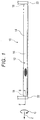
FIG. 1 is a side view of a pressure vessel according to an embodiment; and -
FIG. 2 is an enlarged sectional view illustrating a section of the pressure vessel taken along line II-II inFIG. 1 . - Hereinafter, a pressure vessel according to an example embodiment of the invention will be described with reference to
FIG. 1 andFIG. 2 . -
FIG. 1 illustrates apressure vessel 10 according to the present embodiment. Thepressure vessel 10 is a part of a tank module mounted in, for example, a fuel cell vehicle. The tank module includes a plurality ofpressure vessels 10 connected to each other. - As illustrated in
FIG. 1 andFIG. 2 , thepressure vessel 10 includes aliner 12 and a reinforcinglayer 14. Theliner 12 is configured such that gaseous hydrogen is filled in theliner 12. The reinforcinglayer 14 is configured to cover theliner 12 from outside theliner 12. - As illustrated in
FIG. 2 , theliner 12 is made of a resin material, such as nylon. Theliner 12 has a generally cylindrical shape that are open at both ends. Hereafter, a cylindrical portion of theliner 12, which has a constant inner diameter and a constant outer diameter, will be referred to as abody portion 16. Further, both side portions of theliner 12 in its longitudinal direction (the direction of an arrow Z) will be referred to asshoulder portions 18. Eachshoulder portion 18 has a diameter that gradually decreases in a direction away from thebody portion 16. - The reinforcing
layer 14 is made of a fiber-reinforced resin that is a material having a linear expansion coefficient lower than a linear expansion coefficient of a material of theliner 12. In the present embodiment, a carbon fiber-reinforced resin (referred also to as "carbon fiber-reinforced plastic (CFRP)") is used as the fiber-reinforced resin. The carbon fiber-reinforced resin is wound around the entire outer surface of theliner 12, whereby the reinforcinglayer 14 that covers theliner 12 from outside theliner 12 is formed. -
Caps 22 are respectively engaged, viaseal members 20, with two longitudinally-end portions of theliner 12 covered with the reinforcinglayer 14. With this configuration, one of the open ends of theliner 12 is closed by one of thecaps 22, and the other one of the open ends of theliner 12 is connected to anotherpressure vessel 10 via the other one of thecaps 22. Note that,FIG. 2 illustrates one of the end portions of theliner 12 covered with the reinforcinglayer 14, and the end portion of theliner 12 illustrated inFIG. 2 is closed by thecap 22. - In a state where the fuel cell vehicle equipped with the
pressure vessel 10 described above (equipped with the tank module) is traveling under a low-temperature environment and a fuel cell is operated at maximum power output, the hydrogen that has been filled in theliner 12 of thepressure vessel 10 is rapidly consumed (discharged). Note that, an example of the "state where the fuel cell vehicle is traveling under a low-temperature environment and the fuel cell is operated at maximum power output" is a "state where the fuel cell vehicle is traveling at a maximum speed or traveling on an uphill slope under an environment of -40°C." - When the hydrogen that has been filled in the
liner 12 of thepressure vessel 10 is rapidly consumed in the above-described environment and state, the temperature and pressure inside theliner 12 become both low. In this case, theliner 12 and the reinforcinglayer 14 may be separated from each other (a gap may be formed between theliner 12 and the reinforcing layer 14) due to a difference between the amount of contraction of theliner 12 and the amount of contraction of the reinforcinglayer 14. When hydrogen is filled into the pressure vessel 10 (the tank module) with theliner 12 and the reinforcinglayer 14 separated from each other, first, thebody portion 16 of theliner 12 and the reinforcinglayer 14 come into contact with each other again, and then theshoulder portions 18 of theliner 12 and the reinforcinglayer 14 come into contact with each other again. In the state where thebody portion 16 of theliner 12 and the reinforcinglayer 14 have come into contact with each other again due to filling of the hydrogen into thepressure vessel 10, elongation deformation of thebody portion 16 of theliner 12 in the longitudinal direction of theliner 12 is restrained by a force of friction between thebody portion 16 of theliner 12 and the reinforcinglayer 14. When hydrogen is further filled into thepressure vessel 10 in the state where thebody portion 16 of theliner 12 and the reinforcinglayer 14 have come into contact with each other again, localized elongation occurs at the boundary between thebody portion 16 and eachshoulder portion 18. - In view of this, in the present embodiment, a thickness t of the
body portion 16 of theliner 12 is set to such a thickness that anouter surface 12A of thebody portion 16 of theliner 12 is not separated from an inner peripheral surface (inner surface) 14A of the reinforcinglayer 14 in a state where the temperature and pressure inside theliner 12 become both low. This is because, when theouter surface 12A of thebody portion 16 of theliner 12 is not separated from the innerperipheral surface 14A of the reinforcinglayer 14 in a state where the temperature and pressure inside theliner 12 become both low, it is possible to prevent the occurrence of the above-described phenomenon in which localized elongation occurs at the boundary between thebody portion 16 and eachshoulder portion 18 due to filling of hydrogen into thepressure vessel 10. - Hereafter, t (mm) represents a thickness of the
body portion 16 of theliner body portion 16, and E (MPa) represents an elastic modulus of a material of theliner 12. Further, α (1/K) represents a linear expansion coefficient of the material of theliner 12, ΔT (°C) represents a temperature difference between a temperature of theliner 12 at the time when the reinforcinglayer 14 is formed around theliner 12 and an assumed lowest temperature of theliner 12, and P (MPa) represents a lowest pressure inside theliner 12. - Note that the thickness t (mm) of the
body portion 16 of theliner 12 and theinner diameter 2r (mm) of thebody portion 16 are dimensions (dimensions based on drawing values) at a temperature at the time when the reinforcinglayer 14 is formed around theliner 12. The elastic modulus E (MPa) of the material of theliner 12 is a value at an assumed lowest temperature of theliner 12. Furthermore, the linear expansion coefficient α (1/K) of the material of theliner 12 represents an average of values within a range from the value at the temperature at the time when the reinforcinglayer 14 is formed around theliner 12 to the value at the assumed lowest temperature of theliner 12. The lowest pressure inside theliner 12 is, for example, a lowest system operating pressure (an almost empty gas pressure) in a fuel cell system of the fuel cell vehicle equipped with thepressure vessel 10. - When the above conditions are taken into consideration, a circumferential stress (a stress in the direction of an arrow C in
FIG. 2 ) generated in thebody portion 16 due to the pressure P inside theliner 12 is expressed by Equation (1) below.
- Further, a circumferential stress generated in the
body portion 16 due to thermal contraction of theliner 12 is expressed by Equation (2) below.
- The amount of thermal contraction due to a change in the temperature of a fiber-reinforced resin, such as a carbon fiber-reinforced resin, can be almost disregarded. Therefore, the amount of thermal contraction due to a change in the temperature of the reinforcing
layer 14 is set to zero. - Further, in order to prevent the
outer surface 12A of thebody portion 16 of theliner 12 from being separated from the innerperipheral surface 14A of the reinforcinglayer 14, the thickness t of thebody portion 16 needs to be set to such a value that the value obtained by Equation (1) is greater than the value obtained by Equation (2). That is, the thickness t of thebody portion 16 needs to be set such that Equation (3) below is satisfied.
- Next, an example of the thickness t of the
body portion 16 of theliner 12 will be described below. - In this case, the inner diameter of the
body portion 16 is 82 (mm), and the elastic modulus of the material of theliner 12 is 2.5 (GPa). Further, the linear expansion coefficient of the material of theliner 12 is 13 × 10-5 (1/K), the temperature of theliner 12 at the time when the reinforcinglayer 14 is formed around theliner 12 is 23 °C, the assumed lowest temperature of theliner 12 is -70 °C, and the lowest pressure inside theliner 12 is 0.7 (MPa). Note that, these values are set values of thepressure vessel 10 produced as a prototype, values based on manufacturing conditions, and values obtained based on experiments of a fuel cell vehicle. - Based on the foregoing values and Equation (3), when the thickness t of the
body portion 16 of theliner 12 is set to be less than about 0.9 mm, theouter surface 12A of thebody portion 16 of theliner 12 is not separated from the innerperipheral surface 14A of the reinforcinglayer 14 in a state where the temperature and pressure inside theliner 12 become both low. As a result, when hydrogen is filled into theliner 12 in a state where the temperature and pressure inside theliner 12 become both low, it is possible to reduce the occurrence of localized elongation at the boundary between thebody portion 16 and eachshoulder portion 18 of theliner 12. - When the thickness t of the
body portion 16 of theliner 12 is set to be less than 0.9 mm by a larger amount, theouter surface 12A of thebody portion 16 presses the innerperipheral surface 14A of the reinforcinglayer 14 in a state where the temperature and pressure inside theliner 12 become both low, based on the relationship between Equation (1) and Equation (2). In an example in which the thickness t of thebody portion 16 is set to 0.65 mm, theouter surface 12A of thebody portion 16 presses the innerperipheral surface 14A of the reinforcinglayer 14 with a pressure of 0.2 MPa. In this way, a force of friction between thebody portion 16 of theliner 12 and the reinforcinglayer 14 can always be obtained. As a result, when hydrogen is filled into theliner 12 in a state where the temperature and pressure inside theliner 12 become both low, it is possible to more reliably reduce the occurrence of localized elongation at the boundary between thebody portion 16 of theliner 12 and eachshoulder portion 18 of theliner 12. - When the thickness t of the
body portion 16 of theliner 12 is set to be small, theliner 12 preferably has a multilayer structure of "nylon-an adhesive layer-an ethylene-vinylalcohol-copolymer resin (EVOH)-an adhesive layer-nylon." In this way, it is possible to ensure hydrogen permeation resistance of theliner 12. - In the present embodiment, the thickness t of the
body portion 16 of theliner 12 is derived on the assumption that the temperature of theliner 12 at the time when the reinforcinglayer 14 is formed around theliner 12 is 23 °C and the assumed lowest temperature of theliner 12 is -70 °C. However, the temperature of theliner 12 at the time when the reinforcinglayer 14 is formed around theliner 12 and the assumed lowest temperature of theliner 12 are not limited to the above-described temperatures. These temperatures may be set as appropriate in consideration of variations in the ambient temperature at the time of manufacturing and the environment under which the fuel cell vehicle is used. For example, when the ambient temperature at the time of manufacturing is within a range from 20 °C to 30 °C, a value within this range may be adopted as the "temperature of theliner 12 at the time when the reinforcinglayer 14 is formed around theliner 12." Further, when the lowest temperature under the environment where the fuel cell vehicle is used is within a range from -40 °C to -30 °C, a value obtained in consideration of the values in this range and the experimental values may be adopted as the "assumed lowest temperature of theliner 12." Note that, in a case where the lowest temperature under the environment where the fuel cell vehicle is used is within the range from -40 °C to -30 °C, when the experimental values are taken into consideration, the "assumed lowest temperature of theliner 12" is a value within a range from -70 °C to -60 °C. - In the example described in the present embodiment, the thickness t of the
body portion 16 of theliner 12 is derived in disregard of the amount of thermal contraction due to a change in the temperature of the carbon fiber-reinforced resin of the reinforcinglayer 14. However, the manner of considering the thickness t is not limited to this. When the amount of thermal contraction due to a change in the temperature of the material of the reinforcinglayer 14 cannot be disregarded, the thickness t of thebody portion 16 of theliner 12 may be derived according to Equation (4) below, where α2 (1/K) represents a linear expansion coefficient of the material of the reinforcinglayer 14 and is α1 (1/K) represents a linear expansion coefficient of the material of theliner 12.
- Further, the material of the
liner 12 and the material of the reinforcinglayer 14 may be set as appropriate in consideration of the kind and pressure of a gas to be filled into thepressure vessel 10. - While one example embodiment of the invention has been described above, the invention is not limited to the foregoing embodiment, and various changes and modifications may be made to the foregoing embodiment within the technical scope of the appended claims.
Claims (5)
- A pressure vessel (10) comprising:a liner (12) including a body portion (16) having a cylindrical shape, the liner (12) being configured such that a gas is filled in the liner (12); anda reinforcing layer (14) made of a material having a linear expansion coefficient lower than a linear expansion coefficient of a material of the liner (12), the reinforcing layer (14) being formed in contact with an outer surface (12A) of the body portion (16), and the reinforcing layer (14) being configured to cover the liner (12) from outside the liner (12), whereina thickness of the body portion (16) is set to such a value that the outer surface (12A) of the body portion (16) is not separated from the reinforcing layer (14) when the gas that has been filled in the liner (12) is discharged out of the liner (12).
- The pressure vessel (10) according to claim 1, wherein the thickness of the body portion (16) is set to such a value that the outer surface (12A) of the body portion (16) presses an inner surface of the reinforcing layer (14) when the gas that has been filled in the liner (12) is discharged out of the liner (12).
- The pressure vessel (10) according to claim 1 or 2, wherein:the reinforcing layer (14) is made of a fiber-reinforced resin; andthe thickness (t) of the body portion (16) satisfies an equation below,
 t (mm) represents the thickness of the body portion (16),2r (mm) represents an inner diameter of the body portion (16),E (MPa) represents an elastic modulus of the material of the liner (12),α (1/K) represents the linear expansion coefficient of the material of the liner (12),ΔT (°C) represents a temperature difference between a temperature of the liner (12) at a time when the reinforcing layer (14) is formed around the liner (12) and an assumed lowest temperature of the liner (12), andP (MPa) represents a lowest pressure inside the liner (12).
 - The pressure vessel (10) according to claim 1 or 2, wherein the thickness (t) of the body portion (16) satisfies an equation below,
 t (mm) represents the thickness of the body portion (16),2r (mm) represents an inner diameter of the body portion (16),E (MPa) represents an elastic modulus of the material of the liner (12),α1 (1/K) represents the linear expansion coefficient of the material of the liner (12),α2 (1/K) represents the linear expansion coefficient of the material of the reinforcing layer (14),ΔT (°C) represents a temperature difference between a temperature of the liner (12) at a time when the reinforcing layer (14) is formed around the liner (12) and an assumed lowest temperature of the liner (12), andP (MPa) represents a lowest pressure inside the liner (12).
 - The pressure vessel (10) according to claim 3 or 4, wherein:the gas to be filled in the liner (12) is hydrogen,the temperature of the liner (12) at the time when the reinforcing layer (14) is formed around the liner (12) is within a range from 20 °C to 30 °C, andthe assumed lowest temperature of the liner (12) is within a range from -70 °C to -60 °C.
Applications Claiming Priority (1)
| Application Number | Priority Date | Filing Date | Title |
|---|---|---|---|
| JP2018192439A JP7127470B2 (en) | 2018-10-11 | 2018-10-11 | pressure vessel |
Publications (2)
| Publication Number | Publication Date |
|---|---|
| EP3636981A1 true EP3636981A1 (en) | 2020-04-15 |
| EP3636981B1 EP3636981B1 (en) | 2024-04-24 |
Family
ID=67777228
Family Applications (1)
| Application Number | Title | Priority Date | Filing Date |
|---|---|---|---|
| EP19194136.8A Active EP3636981B1 (en) | 2018-10-11 | 2019-08-28 | Pressure vessel |
Country Status (4)
| Country | Link |
|---|---|
| US (1) | US11346500B2 (en) |
| EP (1) | EP3636981B1 (en) |
| JP (1) | JP7127470B2 (en) |
| CN (1) | CN111043517B (en) |
Citations (4)
| Publication number | Priority date | Publication date | Assignee | Title |
|---|---|---|---|---|
| JPH10274392A (en) * | 1997-03-31 | 1998-10-13 | Kobe Steel Ltd | Frp pressure vessel excellent in external pressure tightness |
| JP2014020440A (en) * | 2012-07-17 | 2014-02-03 | Jfe Container Co Ltd | Container for storing hydrogen |
| JP2015017641A (en) | 2013-07-10 | 2015-01-29 | トヨタ自動車株式会社 | High pressure tank and method for manufacturing high pressure tank |
| US9109750B2 (en) * | 2010-04-23 | 2015-08-18 | Toyota Jidosha Kabushiki Kaisha | Gas filling method, gas filling system, gas station and mobile unit |
Family Cites Families (10)
| Publication number | Priority date | Publication date | Assignee | Title |
|---|---|---|---|---|
| JP2008164134A (en) | 2006-12-28 | 2008-07-17 | Nippon Polyethylene Kk | Pressure vessel and method for manufacturing the same |
| JP4808152B2 (en) | 2006-12-28 | 2011-11-02 | 日本ポリエチレン株式会社 | Pressure vessel and method for manufacturing the same |
| US7857159B2 (en) * | 2008-02-12 | 2010-12-28 | Gm Global Technology Operations, Inc. | Article seal assembly |
| JP2014513250A (en) * | 2011-04-01 | 2014-05-29 | ラクスファー カナダ リミテッド | Multi-layer liner for high pressure gas cylinder |
| JP2016080058A (en) | 2014-10-16 | 2016-05-16 | トヨタ自動車株式会社 | Pressure container |
| CN104455410B (en) | 2014-11-14 | 2016-05-11 | 湖南师范大学 | A kind of outer compression elasticity temperature difference prestressing force external heat self-reinforcing pressure vessel |
| JP6348885B2 (en) | 2015-07-09 | 2018-06-27 | 八千代工業株式会社 | Pressure vessel and method for manufacturing the same |
| JP2018112201A (en) | 2017-01-06 | 2018-07-19 | トヨタ自動車株式会社 | High pressure vessel and method for manufacturing high pressure vessel |
| JP6572913B2 (en) * | 2017-01-06 | 2019-09-11 | トヨタ自動車株式会社 | High pressure vessel |
| JP6614180B2 (en) | 2017-02-21 | 2019-12-04 | トヨタ自動車株式会社 | Method for manufacturing hydrogen tank body, and method for manufacturing hydrogen tank |
-
2018
- 2018-10-11 JP JP2018192439A patent/JP7127470B2/en active Active
-
2019
- 2019-08-28 EP EP19194136.8A patent/EP3636981B1/en active Active
- 2019-09-04 US US16/560,056 patent/US11346500B2/en active Active
- 2019-09-11 CN CN201910858482.7A patent/CN111043517B/en active Active
Patent Citations (4)
| Publication number | Priority date | Publication date | Assignee | Title |
|---|---|---|---|---|
| JPH10274392A (en) * | 1997-03-31 | 1998-10-13 | Kobe Steel Ltd | Frp pressure vessel excellent in external pressure tightness |
| US9109750B2 (en) * | 2010-04-23 | 2015-08-18 | Toyota Jidosha Kabushiki Kaisha | Gas filling method, gas filling system, gas station and mobile unit |
| JP2014020440A (en) * | 2012-07-17 | 2014-02-03 | Jfe Container Co Ltd | Container for storing hydrogen |
| JP2015017641A (en) | 2013-07-10 | 2015-01-29 | トヨタ自動車株式会社 | High pressure tank and method for manufacturing high pressure tank |
Also Published As
| Publication number | Publication date |
|---|---|
| CN111043517A (en) | 2020-04-21 |
| CN111043517B (en) | 2022-10-21 |
| US11346500B2 (en) | 2022-05-31 |
| EP3636981B1 (en) | 2024-04-24 |
| US20200116305A1 (en) | 2020-04-16 |
| JP7127470B2 (en) | 2022-08-30 |
| JP2020060265A (en) | 2020-04-16 |
Similar Documents
| Publication | Publication Date | Title |
|---|---|---|
| US3843010A (en) | Metal lined pressure vessel | |
| US10436388B2 (en) | High-pressure container having hoop layers and helical layers | |
| EP2399061B1 (en) | Pressure vessel shear resistant boss and shell interface element | |
| CN106996511B (en) | Nozzle for pressure vessel and pressure vessel | |
| US8733382B2 (en) | Thermally activated safety valve for pressure vessels | |
| US20130174936A1 (en) | Passive closing device for thermal self-protection of high pressure gas vessels | |
| US6547092B1 (en) | Pressure vessel with thin unstressed metallic liner | |
| US20210215294A1 (en) | High pressure tank | |
| US10928005B2 (en) | Multicapillary system for storing fuel gases | |
| US7624761B2 (en) | Tube shaped high pressure storage tank | |
| EP3475590B1 (en) | Boss with internal bearing | |
| US12013084B2 (en) | High-pressure tank unit | |
| KR20210038786A (en) | Boss for pressure vessel | |
| KR20050039603A (en) | High pressure container and method for manufacturing the same | |
| EP3636981A1 (en) | Pressure vessel | |
| EP3984734B1 (en) | Storage tank for gaseous hydrogen | |
| CN113574307A (en) | Method for producing a barrier layer of a pressure vessel and pressure vessel | |
| JP2016080058A (en) | Pressure container | |
| CN108332040A (en) | Liners for gas tanks and gas tanks | |
| US20130186893A1 (en) | Connection between a metal liner and a composite structure in the mounting region of a tank | |
| JP2014222081A (en) | High pressure gas container | |
| US20220170592A1 (en) | Pressure vessel with circumferential reinforcing elements | |
| CN117730223A (en) | Pressure vessel, pressure vessel system, motor vehicle and method of constructing ribs | |
| US20180347757A1 (en) | Composite pressure vessel assembly with an integrated heating element | |
| CN120231959A (en) | Hydrogen storage tank with a layer containing graphyne |
Legal Events
| Date | Code | Title | Description |
|---|---|---|---|
| PUAI | Public reference made under article 153(3) epc to a published international application that has entered the european phase |
Free format text: ORIGINAL CODE: 0009012 |
|
| STAA | Information on the status of an ep patent application or granted ep patent |
Free format text: STATUS: REQUEST FOR EXAMINATION WAS MADE |
|
| 17P | Request for examination filed |
Effective date: 20190828 |
|
| AK | Designated contracting states |
Kind code of ref document: A1 Designated state(s): AL AT BE BG CH CY CZ DE DK EE ES FI FR GB GR HR HU IE IS IT LI LT LU LV MC MK MT NL NO PL PT RO RS SE SI SK SM TR |
|
| AX | Request for extension of the european patent |
Extension state: BA ME |
|
| STAA | Information on the status of an ep patent application or granted ep patent |
Free format text: STATUS: EXAMINATION IS IN PROGRESS |
|
| 17Q | First examination report despatched |
Effective date: 20220421 |
|
| GRAP | Despatch of communication of intention to grant a patent |
Free format text: ORIGINAL CODE: EPIDOSNIGR1 |
|
| STAA | Information on the status of an ep patent application or granted ep patent |
Free format text: STATUS: GRANT OF PATENT IS INTENDED |
|
| INTG | Intention to grant announced |
Effective date: 20240117 |
|
| GRAS | Grant fee paid |
Free format text: ORIGINAL CODE: EPIDOSNIGR3 |
|
| GRAA | (expected) grant |
Free format text: ORIGINAL CODE: 0009210 |
|
| STAA | Information on the status of an ep patent application or granted ep patent |
Free format text: STATUS: THE PATENT HAS BEEN GRANTED |
|
| AK | Designated contracting states |
Kind code of ref document: B1 Designated state(s): AL AT BE BG CH CY CZ DE DK EE ES FI FR GB GR HR HU IE IS IT LI LT LU LV MC MK MT NL NO PL PT RO RS SE SI SK SM TR |
|
| REG | Reference to a national code |
Ref country code: GB Ref legal event code: FG4D |
|
| REG | Reference to a national code |
Ref country code: CH Ref legal event code: EP |
|
| REG | Reference to a national code |
Ref country code: DE Ref legal event code: R096 Ref document number: 602019050752 Country of ref document: DE |
|
| REG | Reference to a national code |
Ref country code: IE Ref legal event code: FG4D |
|
| REG | Reference to a national code |
Ref country code: LT Ref legal event code: MG9D |
|
| REG | Reference to a national code |
Ref country code: NL Ref legal event code: MP Effective date: 20240424 |
|
| REG | Reference to a national code |
Ref country code: AT Ref legal event code: MK05 Ref document number: 1679960 Country of ref document: AT Kind code of ref document: T Effective date: 20240424 |
|
| PG25 | Lapsed in a contracting state [announced via postgrant information from national office to epo] |
Ref country code: NL Free format text: LAPSE BECAUSE OF FAILURE TO SUBMIT A TRANSLATION OF THE DESCRIPTION OR TO PAY THE FEE WITHIN THE PRESCRIBED TIME-LIMIT Effective date: 20240424 |
|
| PG25 | Lapsed in a contracting state [announced via postgrant information from national office to epo] |
Ref country code: NL Free format text: LAPSE BECAUSE OF FAILURE TO SUBMIT A TRANSLATION OF THE DESCRIPTION OR TO PAY THE FEE WITHIN THE PRESCRIBED TIME-LIMIT Effective date: 20240424 |
|
| PG25 | Lapsed in a contracting state [announced via postgrant information from national office to epo] |
Ref country code: IS Free format text: LAPSE BECAUSE OF FAILURE TO SUBMIT A TRANSLATION OF THE DESCRIPTION OR TO PAY THE FEE WITHIN THE PRESCRIBED TIME-LIMIT Effective date: 20240824 |
|
| PG25 | Lapsed in a contracting state [announced via postgrant information from national office to epo] |
Ref country code: BG Free format text: LAPSE BECAUSE OF FAILURE TO SUBMIT A TRANSLATION OF THE DESCRIPTION OR TO PAY THE FEE WITHIN THE PRESCRIBED TIME-LIMIT Effective date: 20240424 |
|
| PG25 | Lapsed in a contracting state [announced via postgrant information from national office to epo] |
Ref country code: HR Free format text: LAPSE BECAUSE OF FAILURE TO SUBMIT A TRANSLATION OF THE DESCRIPTION OR TO PAY THE FEE WITHIN THE PRESCRIBED TIME-LIMIT Effective date: 20240424 Ref country code: FI Free format text: LAPSE BECAUSE OF FAILURE TO SUBMIT A TRANSLATION OF THE DESCRIPTION OR TO PAY THE FEE WITHIN THE PRESCRIBED TIME-LIMIT Effective date: 20240424 |
|
| PG25 | Lapsed in a contracting state [announced via postgrant information from national office to epo] |
Ref country code: GR Free format text: LAPSE BECAUSE OF FAILURE TO SUBMIT A TRANSLATION OF THE DESCRIPTION OR TO PAY THE FEE WITHIN THE PRESCRIBED TIME-LIMIT Effective date: 20240725 |
|
| PG25 | Lapsed in a contracting state [announced via postgrant information from national office to epo] |
Ref country code: PT Free format text: LAPSE BECAUSE OF FAILURE TO SUBMIT A TRANSLATION OF THE DESCRIPTION OR TO PAY THE FEE WITHIN THE PRESCRIBED TIME-LIMIT Effective date: 20240826 |
|
| PG25 | Lapsed in a contracting state [announced via postgrant information from national office to epo] |
Ref country code: ES Free format text: LAPSE BECAUSE OF FAILURE TO SUBMIT A TRANSLATION OF THE DESCRIPTION OR TO PAY THE FEE WITHIN THE PRESCRIBED TIME-LIMIT Effective date: 20240424 |
|
| PG25 | Lapsed in a contracting state [announced via postgrant information from national office to epo] |
Ref country code: AT Free format text: LAPSE BECAUSE OF FAILURE TO SUBMIT A TRANSLATION OF THE DESCRIPTION OR TO PAY THE FEE WITHIN THE PRESCRIBED TIME-LIMIT Effective date: 20240424 |
|
| PG25 | Lapsed in a contracting state [announced via postgrant information from national office to epo] |
Ref country code: PL Free format text: LAPSE BECAUSE OF FAILURE TO SUBMIT A TRANSLATION OF THE DESCRIPTION OR TO PAY THE FEE WITHIN THE PRESCRIBED TIME-LIMIT Effective date: 20240424 |
|
| PG25 | Lapsed in a contracting state [announced via postgrant information from national office to epo] |
Ref country code: LV Free format text: LAPSE BECAUSE OF FAILURE TO SUBMIT A TRANSLATION OF THE DESCRIPTION OR TO PAY THE FEE WITHIN THE PRESCRIBED TIME-LIMIT Effective date: 20240424 |
|
| PG25 | Lapsed in a contracting state [announced via postgrant information from national office to epo] |
Ref country code: PT Free format text: LAPSE BECAUSE OF FAILURE TO SUBMIT A TRANSLATION OF THE DESCRIPTION OR TO PAY THE FEE WITHIN THE PRESCRIBED TIME-LIMIT Effective date: 20240826 Ref country code: PL Free format text: LAPSE BECAUSE OF FAILURE TO SUBMIT A TRANSLATION OF THE DESCRIPTION OR TO PAY THE FEE WITHIN THE PRESCRIBED TIME-LIMIT Effective date: 20240424 Ref country code: NO Free format text: LAPSE BECAUSE OF FAILURE TO SUBMIT A TRANSLATION OF THE DESCRIPTION OR TO PAY THE FEE WITHIN THE PRESCRIBED TIME-LIMIT Effective date: 20240724 Ref country code: LV Free format text: LAPSE BECAUSE OF FAILURE TO SUBMIT A TRANSLATION OF THE DESCRIPTION OR TO PAY THE FEE WITHIN THE PRESCRIBED TIME-LIMIT Effective date: 20240424 Ref country code: IS Free format text: LAPSE BECAUSE OF FAILURE TO SUBMIT A TRANSLATION OF THE DESCRIPTION OR TO PAY THE FEE WITHIN THE PRESCRIBED TIME-LIMIT Effective date: 20240824 Ref country code: HR Free format text: LAPSE BECAUSE OF FAILURE TO SUBMIT A TRANSLATION OF THE DESCRIPTION OR TO PAY THE FEE WITHIN THE PRESCRIBED TIME-LIMIT Effective date: 20240424 Ref country code: GR Free format text: LAPSE BECAUSE OF FAILURE TO SUBMIT A TRANSLATION OF THE DESCRIPTION OR TO PAY THE FEE WITHIN THE PRESCRIBED TIME-LIMIT Effective date: 20240725 Ref country code: FI Free format text: LAPSE BECAUSE OF FAILURE TO SUBMIT A TRANSLATION OF THE DESCRIPTION OR TO PAY THE FEE WITHIN THE PRESCRIBED TIME-LIMIT Effective date: 20240424 Ref country code: ES Free format text: LAPSE BECAUSE OF FAILURE TO SUBMIT A TRANSLATION OF THE DESCRIPTION OR TO PAY THE FEE WITHIN THE PRESCRIBED TIME-LIMIT Effective date: 20240424 Ref country code: BG Free format text: LAPSE BECAUSE OF FAILURE TO SUBMIT A TRANSLATION OF THE DESCRIPTION OR TO PAY THE FEE WITHIN THE PRESCRIBED TIME-LIMIT Effective date: 20240424 Ref country code: AT Free format text: LAPSE BECAUSE OF FAILURE TO SUBMIT A TRANSLATION OF THE DESCRIPTION OR TO PAY THE FEE WITHIN THE PRESCRIBED TIME-LIMIT Effective date: 20240424 Ref country code: RS Free format text: LAPSE BECAUSE OF FAILURE TO SUBMIT A TRANSLATION OF THE DESCRIPTION OR TO PAY THE FEE WITHIN THE PRESCRIBED TIME-LIMIT Effective date: 20240724 |
|
| P01 | Opt-out of the competence of the unified patent court (upc) registered |
Free format text: CASE NUMBER: APP_57182/2024 Effective date: 20241019 |
|
| REG | Reference to a national code |
Ref country code: DE Ref legal event code: R084 Ref document number: 602019050752 Country of ref document: DE |
|
| PG25 | Lapsed in a contracting state [announced via postgrant information from national office to epo] |
Ref country code: DK Free format text: LAPSE BECAUSE OF FAILURE TO SUBMIT A TRANSLATION OF THE DESCRIPTION OR TO PAY THE FEE WITHIN THE PRESCRIBED TIME-LIMIT Effective date: 20240424 |
|
| PG25 | Lapsed in a contracting state [announced via postgrant information from national office to epo] |
Ref country code: EE Free format text: LAPSE BECAUSE OF FAILURE TO SUBMIT A TRANSLATION OF THE DESCRIPTION OR TO PAY THE FEE WITHIN THE PRESCRIBED TIME-LIMIT Effective date: 20240424 |
|
| PG25 | Lapsed in a contracting state [announced via postgrant information from national office to epo] |
Ref country code: CZ Free format text: LAPSE BECAUSE OF FAILURE TO SUBMIT A TRANSLATION OF THE DESCRIPTION OR TO PAY THE FEE WITHIN THE PRESCRIBED TIME-LIMIT Effective date: 20240424 |
|
| PG25 | Lapsed in a contracting state [announced via postgrant information from national office to epo] |
Ref country code: SK Free format text: LAPSE BECAUSE OF FAILURE TO SUBMIT A TRANSLATION OF THE DESCRIPTION OR TO PAY THE FEE WITHIN THE PRESCRIBED TIME-LIMIT Effective date: 20240424 Ref country code: RO Free format text: LAPSE BECAUSE OF FAILURE TO SUBMIT A TRANSLATION OF THE DESCRIPTION OR TO PAY THE FEE WITHIN THE PRESCRIBED TIME-LIMIT Effective date: 20240424 |
|
| REG | Reference to a national code |
Ref country code: DE Ref legal event code: R097 Ref document number: 602019050752 Country of ref document: DE |
|
| PG25 | Lapsed in a contracting state [announced via postgrant information from national office to epo] |
Ref country code: SM Free format text: LAPSE BECAUSE OF FAILURE TO SUBMIT A TRANSLATION OF THE DESCRIPTION OR TO PAY THE FEE WITHIN THE PRESCRIBED TIME-LIMIT Effective date: 20240424 |
|
| PG25 | Lapsed in a contracting state [announced via postgrant information from national office to epo] |
Ref country code: SM Free format text: LAPSE BECAUSE OF FAILURE TO SUBMIT A TRANSLATION OF THE DESCRIPTION OR TO PAY THE FEE WITHIN THE PRESCRIBED TIME-LIMIT Effective date: 20240424 Ref country code: SK Free format text: LAPSE BECAUSE OF FAILURE TO SUBMIT A TRANSLATION OF THE DESCRIPTION OR TO PAY THE FEE WITHIN THE PRESCRIBED TIME-LIMIT Effective date: 20240424 Ref country code: RO Free format text: LAPSE BECAUSE OF FAILURE TO SUBMIT A TRANSLATION OF THE DESCRIPTION OR TO PAY THE FEE WITHIN THE PRESCRIBED TIME-LIMIT Effective date: 20240424 Ref country code: EE Free format text: LAPSE BECAUSE OF FAILURE TO SUBMIT A TRANSLATION OF THE DESCRIPTION OR TO PAY THE FEE WITHIN THE PRESCRIBED TIME-LIMIT Effective date: 20240424 Ref country code: DK Free format text: LAPSE BECAUSE OF FAILURE TO SUBMIT A TRANSLATION OF THE DESCRIPTION OR TO PAY THE FEE WITHIN THE PRESCRIBED TIME-LIMIT Effective date: 20240424 Ref country code: CZ Free format text: LAPSE BECAUSE OF FAILURE TO SUBMIT A TRANSLATION OF THE DESCRIPTION OR TO PAY THE FEE WITHIN THE PRESCRIBED TIME-LIMIT Effective date: 20240424 |
|
| PLBE | No opposition filed within time limit |
Free format text: ORIGINAL CODE: 0009261 |
|
| STAA | Information on the status of an ep patent application or granted ep patent |
Free format text: STATUS: NO OPPOSITION FILED WITHIN TIME LIMIT |
|
| REG | Reference to a national code |
Ref country code: CH Ref legal event code: PL |
|
| 26N | No opposition filed |
Effective date: 20250127 |
|
| PG25 | Lapsed in a contracting state [announced via postgrant information from national office to epo] |
Ref country code: LU Free format text: LAPSE BECAUSE OF NON-PAYMENT OF DUE FEES Effective date: 20240828 |
|
| GBPC | Gb: european patent ceased through non-payment of renewal fee |
Effective date: 20240828 |
|
| PG25 | Lapsed in a contracting state [announced via postgrant information from national office to epo] |
Ref country code: CH Free format text: LAPSE BECAUSE OF NON-PAYMENT OF DUE FEES Effective date: 20240831 Ref country code: SI Free format text: LAPSE BECAUSE OF FAILURE TO SUBMIT A TRANSLATION OF THE DESCRIPTION OR TO PAY THE FEE WITHIN THE PRESCRIBED TIME-LIMIT Effective date: 20240424 Ref country code: MC Free format text: LAPSE BECAUSE OF FAILURE TO SUBMIT A TRANSLATION OF THE DESCRIPTION OR TO PAY THE FEE WITHIN THE PRESCRIBED TIME-LIMIT Effective date: 20240424 |
|
| REG | Reference to a national code |
Ref country code: BE Ref legal event code: MM Effective date: 20240831 |
|
| PG25 | Lapsed in a contracting state [announced via postgrant information from national office to epo] |
Ref country code: GB Free format text: LAPSE BECAUSE OF NON-PAYMENT OF DUE FEES Effective date: 20240828 |
|
| PG25 | Lapsed in a contracting state [announced via postgrant information from national office to epo] |
Ref country code: BE Free format text: LAPSE BECAUSE OF NON-PAYMENT OF DUE FEES Effective date: 20240831 |
|
| PG25 | Lapsed in a contracting state [announced via postgrant information from national office to epo] |
Ref country code: FR Free format text: LAPSE BECAUSE OF NON-PAYMENT OF DUE FEES Effective date: 20240831 |
|
| PG25 | Lapsed in a contracting state [announced via postgrant information from national office to epo] |
Ref country code: IE Free format text: LAPSE BECAUSE OF NON-PAYMENT OF DUE FEES Effective date: 20240828 |
|
| PG25 | Lapsed in a contracting state [announced via postgrant information from national office to epo] |
Ref country code: SE Free format text: LAPSE BECAUSE OF FAILURE TO SUBMIT A TRANSLATION OF THE DESCRIPTION OR TO PAY THE FEE WITHIN THE PRESCRIBED TIME-LIMIT Effective date: 20240424 |
|
| PGFP | Annual fee paid to national office [announced via postgrant information from national office to epo] |
Ref country code: DE Payment date: 20250702 Year of fee payment: 7 |
|
| PG25 | Lapsed in a contracting state [announced via postgrant information from national office to epo] |
Ref country code: CY Free format text: LAPSE BECAUSE OF FAILURE TO SUBMIT A TRANSLATION OF THE DESCRIPTION OR TO PAY THE FEE WITHIN THE PRESCRIBED TIME-LIMIT; INVALID AB INITIO Effective date: 20190828 Ref country code: IT Free format text: LAPSE BECAUSE OF FAILURE TO SUBMIT A TRANSLATION OF THE DESCRIPTION OR TO PAY THE FEE WITHIN THE PRESCRIBED TIME-LIMIT Effective date: 20240424 |
|
| PG25 | Lapsed in a contracting state [announced via postgrant information from national office to epo] |
Ref country code: HU Free format text: LAPSE BECAUSE OF FAILURE TO SUBMIT A TRANSLATION OF THE DESCRIPTION OR TO PAY THE FEE WITHIN THE PRESCRIBED TIME-LIMIT; INVALID AB INITIO Effective date: 20190828 |