EP3636903B1 - Cold start management system for a diesel combustion engine - Google Patents
Cold start management system for a diesel combustion engine Download PDFInfo
- Publication number
- EP3636903B1 EP3636903B1 EP19202838.9A EP19202838A EP3636903B1 EP 3636903 B1 EP3636903 B1 EP 3636903B1 EP 19202838 A EP19202838 A EP 19202838A EP 3636903 B1 EP3636903 B1 EP 3636903B1
- Authority
- EP
- European Patent Office
- Prior art keywords
- engine
- gap
- piston
- basis
- inputs
- Prior art date
- Legal status (The legal status is an assumption and is not a legal conclusion. Google has not performed a legal analysis and makes no representation as to the accuracy of the status listed.)
- Active
Links
Images
Classifications
-
- F—MECHANICAL ENGINEERING; LIGHTING; HEATING; WEAPONS; BLASTING
- F02—COMBUSTION ENGINES; HOT-GAS OR COMBUSTION-PRODUCT ENGINE PLANTS
- F02D—CONTROLLING COMBUSTION ENGINES
- F02D41/00—Electrical control of supply of combustible mixture or its constituents
- F02D41/02—Circuit arrangements for generating control signals
- F02D41/04—Introducing corrections for particular operating conditions
- F02D41/06—Introducing corrections for particular operating conditions for engine starting or warming up
- F02D41/062—Introducing corrections for particular operating conditions for engine starting or warming up for starting
- F02D41/064—Introducing corrections for particular operating conditions for engine starting or warming up for starting at cold start
-
- F—MECHANICAL ENGINEERING; LIGHTING; HEATING; WEAPONS; BLASTING
- F02—COMBUSTION ENGINES; HOT-GAS OR COMBUSTION-PRODUCT ENGINE PLANTS
- F02D—CONTROLLING COMBUSTION ENGINES
- F02D15/00—Varying compression ratio
-
- F—MECHANICAL ENGINEERING; LIGHTING; HEATING; WEAPONS; BLASTING
- F02—COMBUSTION ENGINES; HOT-GAS OR COMBUSTION-PRODUCT ENGINE PLANTS
- F02D—CONTROLLING COMBUSTION ENGINES
- F02D41/00—Electrical control of supply of combustible mixture or its constituents
- F02D41/24—Electrical control of supply of combustible mixture or its constituents characterised by the use of digital means
- F02D41/2406—Electrical control of supply of combustible mixture or its constituents characterised by the use of digital means using essentially read only memories
- F02D41/2425—Particular ways of programming the data
- F02D41/2429—Methods of calibrating or learning
- F02D41/2451—Methods of calibrating or learning characterised by what is learned or calibrated
-
- F—MECHANICAL ENGINEERING; LIGHTING; HEATING; WEAPONS; BLASTING
- F02—COMBUSTION ENGINES; HOT-GAS OR COMBUSTION-PRODUCT ENGINE PLANTS
- F02D—CONTROLLING COMBUSTION ENGINES
- F02D2200/00—Input parameters for engine control
- F02D2200/02—Input parameters for engine control the parameters being related to the engine
- F02D2200/021—Engine temperature
-
- F—MECHANICAL ENGINEERING; LIGHTING; HEATING; WEAPONS; BLASTING
- F02—COMBUSTION ENGINES; HOT-GAS OR COMBUSTION-PRODUCT ENGINE PLANTS
- F02D—CONTROLLING COMBUSTION ENGINES
- F02D2200/00—Input parameters for engine control
- F02D2200/02—Input parameters for engine control the parameters being related to the engine
- F02D2200/025—Engine noise, e.g. determined by using an acoustic sensor
-
- F—MECHANICAL ENGINEERING; LIGHTING; HEATING; WEAPONS; BLASTING
- F02—COMBUSTION ENGINES; HOT-GAS OR COMBUSTION-PRODUCT ENGINE PLANTS
- F02D—CONTROLLING COMBUSTION ENGINES
- F02D2200/00—Input parameters for engine control
- F02D2200/02—Input parameters for engine control the parameters being related to the engine
- F02D2200/10—Parameters related to the engine output, e.g. engine torque or engine speed
- F02D2200/101—Engine speed
-
- F—MECHANICAL ENGINEERING; LIGHTING; HEATING; WEAPONS; BLASTING
- F02—COMBUSTION ENGINES; HOT-GAS OR COMBUSTION-PRODUCT ENGINE PLANTS
- F02D—CONTROLLING COMBUSTION ENGINES
- F02D2700/00—Mechanical control of speed or power of a single cylinder piston engine
- F02D2700/03—Controlling by changing the compression ratio
Definitions
- the present invention relates to the combustion of a diesel engine and in particular to manage cold start.
- One of the first internal combustion engine capable to vary the engine compression was Saab Variable Compression engine.
- the US patent N. 5025757 discloses a solution where the block is mounted on the crankcase for pivotal movement about a pivot axis parallel to and spaced apart from the axis of the crank such that the size of the compression volume varies in accordance with the extent of the pivotal movement of the block about the pivot axis.
- the aim of such solution is to minimize the clearance volume within the cylinder according to the engine load.
- the compression ratio is calculated as swept volume + clearance volume divided for clearance volume.
- the swept volume is determined by the piston displacement between the top dead center and the bottom dead center, while the clearance volume is defined substantially by the combustion chamber and the gap between the piston crown and the engine head.
- the minimum gap between the pistons and the engine head is usually about 1.2 mm and selected as the result of a statistic tolerance chain, assuring that there is no collision with the engine head or valves in any operating condition, especially at high speed.
- DE 11 2016 001786 T5 discloses an internal combustion engine with variable compression ratio. The compression ratio and the expansion ratio can be adjusted separately. The compression ratio is set to avoid contact to the intake and exhaust valves at high speed and can also take into account a variable valve lift.
- the main object of the present invention to improve engine performances.
- the basic idea of the present invention is to implement a system for compression ratio variation suitable to adjust the gap between the piston and the relating engine head, arranged and/or configured to maintain said gap, as much as possible close to zero in a diesel engine, in any fired operating condition.
- said gap control is realized on the basis of the engine temperature, thanks to minimization and/or control means.
- US5025757 is suitable to adjust the distance between the crankshaft and the engine head due to a pivoting coupling between the engine block with its own crankcase.
- the engine head position can translate with respect to the engine block.
- the crankshaft is supported by an eccentric bushing.
- the piston rod has an adjustable length as in US2018179949 .
- the distance between the engine head and the engine crankshaft is virtually varied.
- the gap control is realized also on the basis of the engine speed, thanks to said minimization and/or control means. More in particular the distance, at least virtual, between the engine head and the engine crankshaft is increased according to the engine speed increase, in order to avoid collisions between piston and engine head.
- a look up table can be implemented to control the gap as a function of the engine temperature and speed.
- a further parameter is implemented to control said gap.
- This parameter is the signal generated by a noise sensor associated with the engine head.
- the aim is to detect initial slight impacts between said piston and said engine head, wherein the gap is adjusted on the basis of the signal generated by the noise sensor, thereby increasing the above gap when such initial slight impact is detected.
- the noise sensor is arranged in a sort of learning process which upgrades the above look up table. Indeed, the wear of the engine sliding components could lead to the increase of tolerances over the time. Thus, said parameter not only is exploited to directly adjust the gap, but also to correct the above look up table.
- the above gap control is applied to a diesel combustion engine.
- the aim of the present invention is achieved through gap minimization/elimination of a diesel engine according to claim 1.
- the gap is considered to be zero when it is between 0.01 and 0.2 mm according to the machining tolerances of the head and the piston crown. Even considering 0.2 mm, the clearance volume is relevantly reduced.
- second element does not imply the presence of a "first element”, first, second, etc.. are used only for improving the clarity of the description and they should not be interpreted in a limiting way.
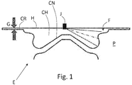
- Figure 1 discloses a piston P at its TDC position.
- a gap G is defined between the piston P and its relating cylinder head.
- the piston has a crown CR, circa circumferentially flat, while in central portion of the crown the combustion engine CH is arranged.
- the piston and its head could have different shapes with respect to the example in figure 1 .
- a portion of the combustion chamber is defined also in a cavity of the head.
- the gap between the circumferential portion of the piston and the head does not participate to the combustion, therefore, the aim of the present invention is to reduce such gap as much as possible to improve combustion efficiency.
- the gap control is executed on the basis of the engine temperature.
- the engine temperature can be measured through a sensor associated to an engine cooling circuit and/or an engine lubricating circuit.
- the gap control is executed also on the basis of the engine speed. This control can be applied in order to achieve a further reduction of the gap, with respect to the sole temperature control.
- the gap is controlled as a response of a feedback of a noise sensor associated with the cylinder head.
- a look up table can be used with said two entries, temperature/speed, to manage the gap control.
- the noise sensor can be preferably implemented to modify the look up table so as to account for engine wear.
- This invention can be implemented advantageously in a computer program arranged and/or configured to manage system to control piston TDC and programmed to implement the present invention.
- the computer program comprising program code means for performing one or more steps of such method, when such program is run on a computer.
- the patent shall also cover such computer program and the computer-readable medium that comprises a recorded message, such computer-readable medium comprising the program code means for performing one or more steps of such method, when such program is run on a computer.
Landscapes
- Engineering & Computer Science (AREA)
- Chemical & Material Sciences (AREA)
- Combustion & Propulsion (AREA)
- Mechanical Engineering (AREA)
- General Engineering & Computer Science (AREA)
- Output Control And Ontrol Of Special Type Engine (AREA)
- Cylinder Crankcases Of Internal Combustion Engines (AREA)
Description
- This patent application claims priority from
Italian patent application no. 102018000009373 - The present invention relates to the combustion of a diesel engine and in particular to manage cold start.
- One of the first internal combustion engine capable to vary the engine compression was Saab Variable Compression engine.
- The
US patent N. 5025757 discloses a solution where the block is mounted on the crankcase for pivotal movement about a pivot axis parallel to and spaced apart from the axis of the crank such that the size of the compression volume varies in accordance with the extent of the pivotal movement of the block about the pivot axis. - The aim of such solution is to minimize the clearance volume within the cylinder according to the engine load.
- The compression ratio is calculated as swept volume + clearance volume divided for clearance volume.
- The swept volume is determined by the piston displacement between the top dead center and the bottom dead center, while the clearance volume is defined substantially by the combustion chamber and the gap between the piston crown and the engine head.
- The minimum gap between the pistons and the engine head is usually about 1.2 mm and selected as the result of a statistic tolerance chain, assuring that there is no collision with the engine head or valves in any operating condition, especially at high speed.
DE 11 2016 001786 T5 discloses an internal combustion engine with variable compression ratio. The compression ratio and the expansion ratio can be adjusted separately. The compression ratio is set to avoid contact to the intake and exhaust valves at high speed and can also take into account a variable valve lift. - The main object of the present invention to improve engine performances.
- The basic idea of the present invention is to implement a system for compression ratio variation suitable to adjust the gap between the piston and the relating engine head, arranged and/or configured to maintain said gap, as much as possible close to zero in a diesel engine, in any fired operating condition.
- The application of a gap control strategy to a diesel engine implies that such control departs from the load applied to the engine, being the load managed by adjusting the fuel injection.
- According to a first embodiment of the invention, said gap control is realized on the basis of the engine temperature, thanks to minimization and/or control means.
- While in
US5025757 the gap is selected to achieve optimal working temperature and pressure, here the aim is to assure the minimum gap possible in any engine operating condition. Several are the mechanical components coupling the piston and the engine head on which the control of the present invention can apply, so that the invention is not limited by the specific kind of mechanical components used to adjust/minimize/eliminate the gap. - For example,
US5025757 is suitable to adjust the distance between the crankshaft and the engine head due to a pivoting coupling between the engine block with its own crankcase. - According to other solutions, still by way of example, the engine head position can translate with respect to the engine block. According to another known solution the crankshaft is supported by an eccentric bushing. According to a further known solution, the piston rod has an adjustable length as in
US2018179949 . - Nevertheless, also in this case the distance between the engine head and the engine crankshaft is virtually varied. According to a second embodiment of the invention that can be combined with the previous one, the gap control is realized also on the basis of the engine speed, thanks to said minimization and/or control means. More in particular the distance, at least virtual, between the engine head and the engine crankshaft is increased according to the engine speed increase, in order to avoid collisions between piston and engine head.
- Therefore, a look up table can be implemented to control the gap as a function of the engine temperature and speed. According to the invention, a further parameter is implemented to control said gap. This parameter is the signal generated by a noise sensor associated with the engine head. Indeed, the aim is to detect initial slight impacts between said piston and said engine head, wherein the gap is adjusted on the basis of the signal generated by the noise sensor, thereby increasing the above gap when such initial slight impact is detected.
- According to a preferred embodiment of the invention, the noise sensor is arranged in a sort of learning process which upgrades the above look up table. Indeed, the wear of the engine sliding components could lead to the increase of tolerances over the time. Thus, said parameter not only is exploited to directly adjust the gap, but also to correct the above look up table.
- Even a small sectional impact can be foreseen when the piston crown is not completely parallel to the cylinder head flame deck.
- Thanks to the present invention, improved fuel consumption is achieved due to a higher combustion efficiency and/or lower air pumping requirement for same combustion air fuel ratio.
- According to the invention, the above gap control is applied to a diesel combustion engine. The aim of the present invention is achieved through gap minimization/elimination of a diesel engine according to claim 1.
- According to the present invention, the gap is considered to be zero when it is between 0.01 and 0.2 mm according to the machining tolerances of the head and the piston crown. Even considering 0.2 mm, the clearance volume is relevantly reduced.
- These and further objects are achieved by means of the attached claims, which describe preferred embodiments of the invention, forming an integral part of the present description.
- The invention will become fully clear from the following detailed description, given by way of a mere exemplifying and non limiting example, to be read with reference to the attached drawing figures, wherein:
-
Fig. 1 shows a longitudinal section of a piston coupled with the head of a cylinder, wherein the piston is at TDC where a gap is defined between the piston crown and the head. - The same reference numerals and letters in the figures designate the same or functionally equivalent parts.
- According to the present invention, the term "second element" does not imply the presence of a "first element", first, second, etc.. are used only for improving the clarity of the description and they should not be interpreted in a limiting way.
-
Figure 1 discloses a piston P at its TDC position. - A gap G is defined between the piston P and its relating cylinder head.
- In particular, the piston has a crown CR, circa circumferentially flat, while in central portion of the crown the combustion engine CH is arranged.
- It should be understood that the piston and its head could have different shapes with respect to the example in
figure 1 . For example, a portion of the combustion chamber is defined also in a cavity of the head. Nevertheless, the gap between the circumferential portion of the piston and the head does not participate to the combustion, therefore, the aim of the present invention is to reduce such gap as much as possible to improve combustion efficiency. - According to the invention, the gap control is executed on the basis of the engine temperature.
- The engine temperature can be measured through a sensor associated to an engine cooling circuit and/or an engine lubricating circuit.
- Usually water is implemented to cool the engine, while oil is implemented both to lubricate and cool the engine. Therefore, the gap is adjusted during thermal transient. According to a further embodiment of the invention, the gap control is executed also on the basis of the engine speed. This control can be applied in order to achieve a further reduction of the gap, with respect to the sole temperature control.
- According to the invention, the gap is controlled as a response of a feedback of a noise sensor associated with the cylinder head.
- Preferably, a look up table can be used with said two entries, temperature/speed, to manage the gap control.
- The noise sensor can be preferably implemented to modify the look up table so as to account for engine wear.
- Any known solution to vary the engine compression ratio can be implemented to maintain said gap constantly close to zero.
- It will be apparent to those skilled in the art that specific details need not be described, that example embodiments may be embodied in many different forms and that neither should be construed to limit the scope of the disclosure. The scope of protection is defined by the appended claims.
- In some example embodiments, well known processes, well-known device structures, and well known technologies are not described in detail.
- This invention can be implemented advantageously in a computer program arranged and/or configured to manage system to control piston TDC and programmed to implement the present invention. The computer program comprising program code means for performing one or more steps of such method, when such program is run on a computer. For this reason, the patent shall also cover such computer program and the computer-readable medium that comprises a recorded message, such computer-readable medium comprising the program code means for performing one or more steps of such method, when such program is run on a computer.
- The features disclosed in the prior art background are introduced only in order to better understand the invention and not as a declaration about the existence of known prior art. In addition, said features define the context of the present invention, thus such features shall be considered in common with the detailed description.
- Further implementation details will not be described, as the man skilled in the art is able to carry out the invention starting from the teaching of the above description.
Claims (9)
- Cold start management system, comprising:- a diesel combustion engine (E), comprising a cylinder, a piston (P) mounted for reciprocating movement in the cylinder, a cylinder head (H) mounted to overlie the cylinder;- the cylinder and a face (F) of the piston defining a combustion chamber (CH) and a surface (CR) surrounding the combustion chamber;
wherein said reciprocating movement defines, when the piston is in a top dead center position with respect to said cylinder head, a gap (G) between said surface (CR) and said cylinder head (H);- minimization means configured to minimize said gap on the basis of an engine temperature;characterized by comprising a noise sensor associated with said engine head, wherein said gap (G) is adjusted on the basis of a signal generated by said noise sensor, thereby increasing said gap (G) when a slight collision is detected between said piston (P) and said engine head (H). - System according to claim 1, wherein the engine comprises a temperature sensor associated with an engine coolant circuit and/or an engine lubricating circuit.
- System according to any one of previous claims 1 or 2, wherein the system further comprises speed sensor means arranged to measure an engine speed and wherein said minimization means are arranged to minimize said gap on the basis of an engine speed also.
- System according to claim 1, wherein said minimizing means are arranged to implement a look up table having two inputs and said gap adjustment as output; wherein a first input of said two inputs is said measured temperature and a second input of said two inputs is said engine speed and wherein said minimizing means are arranged to modify said look up table when a slight collision is sensed by said noise sensor.
- Method for cold start management for a system according to any one of the foregoing claims, the method comprising a minimization step of minimizing said gap on the basis of an engine temperature; and- an adjusting step for adjusting said gap (G) on the basis of a signal generated by a noise sensor, thereby increasing said gap (G) when a slight collision is detected between said piston (P) and said engine head (H).
- Method according to claim 5, wherein minimization step is carried out also on the basis of an engine speed.
- Method according to claim 6, wherein a look up table is implemented with two inputs and said gap adjustment as output; wherein a first input of said two inputs is said measured temperature and a second input of said two inputs is said engine speed and wherein said minimizing means are arranged to modify said look up table when a slight collision is sensed by said noise sensor.
- Engine control unit configured for carrying out the method of claim 5 to 7 in a system according to any one of claims 1 to 4.
- Terrestrial vehicle comprising the diesel combustion engine of claim 8.
Applications Claiming Priority (1)
| Application Number | Priority Date | Filing Date | Title |
|---|---|---|---|
| IT102018000009373A IT201800009373A1 (en) | 2018-10-11 | 2018-10-11 | COLD START MANAGEMENT SYSTEM FOR A DIESEL INTERNAL COMBUSTION ENGINE |
Publications (2)
| Publication Number | Publication Date |
|---|---|
| EP3636903A1 EP3636903A1 (en) | 2020-04-15 |
| EP3636903B1 true EP3636903B1 (en) | 2021-08-25 |
Family
ID=64744885
Family Applications (1)
| Application Number | Title | Priority Date | Filing Date |
|---|---|---|---|
| EP19202838.9A Active EP3636903B1 (en) | 2018-10-11 | 2019-10-11 | Cold start management system for a diesel combustion engine |
Country Status (2)
| Country | Link |
|---|---|
| EP (1) | EP3636903B1 (en) |
| IT (1) | IT201800009373A1 (en) |
Family Cites Families (9)
| Publication number | Priority date | Publication date | Assignee | Title |
|---|---|---|---|---|
| US5025757A (en) | 1990-09-13 | 1991-06-25 | Larsen Gregory J | Reciprocating piston engine with a varying compression ratio |
| US6631708B1 (en) * | 2000-10-12 | 2003-10-14 | Ford Global Technologies, Llc | Control method for engine |
| US6970781B1 (en) * | 2004-06-03 | 2005-11-29 | Ford Global Technologies, Llc | Compression ratio mode selection logic for an internal combustion engine having discrete variable compression ratio control mechanism |
| JP5177303B2 (en) * | 2009-12-28 | 2013-04-03 | トヨタ自動車株式会社 | Spark ignition internal combustion engine |
| JP6094599B2 (en) * | 2013-02-01 | 2017-03-15 | 日産自動車株式会社 | Control device and control method for internal combustion engine |
| JP6408419B2 (en) * | 2015-04-17 | 2018-10-17 | 日立オートモティブシステムズ株式会社 | Internal combustion engine compression ratio adjusting device |
| DE102017121425A1 (en) | 2016-12-22 | 2018-06-28 | ECO Holding 1 GmbH | Connecting rod for a variable compression internal combustion engine |
| US10202912B2 (en) * | 2017-06-20 | 2019-02-12 | Ford Global Technologies, Llc | System and method for reducing variable compression ratio engine shutdown shake |
| DE102017116244A1 (en) * | 2017-07-19 | 2019-01-24 | Volkswagen Aktiengesellschaft | Internal combustion engine and method for operating an internal combustion engine |
-
2018
- 2018-10-11 IT IT102018000009373A patent/IT201800009373A1/en unknown
-
2019
- 2019-10-11 EP EP19202838.9A patent/EP3636903B1/en active Active
Also Published As
| Publication number | Publication date |
|---|---|
| EP3636903A1 (en) | 2020-04-15 |
| IT201800009373A1 (en) | 2020-04-11 |
Similar Documents
| Publication | Publication Date | Title |
|---|---|---|
| US8646419B2 (en) | Control apparatus for internal combustion engine | |
| KR100980863B1 (en) | Variable compression ratio device for automobile engine | |
| US6736092B2 (en) | Internal-combustion engine with an electronically controlled hydraulic system for actuation of the valves and means for compensating changes in the operating conditions of the hydraulic | |
| US5005540A (en) | Valve timing control system for an internal combustion engine | |
| US9951712B2 (en) | Internal combustion engine with interbore cooling | |
| US20170167430A1 (en) | Cylinder liner for an internal combustion engine | |
| MD1211C2 (en) | An internal combustion engine | |
| EP3636903B1 (en) | Cold start management system for a diesel combustion engine | |
| JP7749960B2 (en) | Engine lubrication system | |
| JP2013181521A (en) | High-pressure fuel pump driving device | |
| EP3918191B1 (en) | Method for providing variable compression ratio in a diesel engine and diesel engine for the method | |
| EP3428429B1 (en) | Control method for internal combustion engine and control device for internal combustion engine | |
| JP2020007970A (en) | Internal combustion engine | |
| US6463903B1 (en) | Piston assembly for free piston internal combustion engine | |
| JPH0330600Y2 (en) | ||
| JPS63143342A (en) | Compression ratio variable device for engine | |
| KR100999623B1 (en) | Variable compression ratio device and engine using same | |
| KR20020022997A (en) | Oil jet for cylinder | |
| HK1243757A1 (en) | Diesel engine and method for starting a diesel engine | |
| JP2020007934A (en) | Internal combustion engine | |
| JP2009085019A (en) | Variable compression ratio internal combustion engine with reduced temperature effect | |
| JP2021055562A (en) | Internal combustion engine control device and control method | |
| KR970003065Y1 (en) | One-piece cylinder | |
| JP2025008935A (en) | Engine Control Unit | |
| KR0131176Y1 (en) | Variable connecting rod |
Legal Events
| Date | Code | Title | Description |
|---|---|---|---|
| PUAI | Public reference made under article 153(3) epc to a published international application that has entered the european phase |
Free format text: ORIGINAL CODE: 0009012 |
|
| STAA | Information on the status of an ep patent application or granted ep patent |
Free format text: STATUS: THE APPLICATION HAS BEEN PUBLISHED |
|
| AK | Designated contracting states |
Kind code of ref document: A1 Designated state(s): AL AT BE BG CH CY CZ DE DK EE ES FI FR GB GR HR HU IE IS IT LI LT LU LV MC MK MT NL NO PL PT RO RS SE SI SK SM TR |
|
| STAA | Information on the status of an ep patent application or granted ep patent |
Free format text: STATUS: REQUEST FOR EXAMINATION WAS MADE |
|
| 17P | Request for examination filed |
Effective date: 20201007 |
|
| RBV | Designated contracting states (corrected) |
Designated state(s): AL AT BE BG CH CY CZ DE DK EE ES FI FR GB GR HR HU IE IS IT LI LT LU LV MC MK MT NL NO PL PT RO RS SE SI SK SM TR |
|
| GRAP | Despatch of communication of intention to grant a patent |
Free format text: ORIGINAL CODE: EPIDOSNIGR1 |
|
| STAA | Information on the status of an ep patent application or granted ep patent |
Free format text: STATUS: GRANT OF PATENT IS INTENDED |
|
| INTG | Intention to grant announced |
Effective date: 20210317 |
|
| GRAS | Grant fee paid |
Free format text: ORIGINAL CODE: EPIDOSNIGR3 |
|
| GRAA | (expected) grant |
Free format text: ORIGINAL CODE: 0009210 |
|
| STAA | Information on the status of an ep patent application or granted ep patent |
Free format text: STATUS: THE PATENT HAS BEEN GRANTED |
|
| AK | Designated contracting states |
Kind code of ref document: B1 Designated state(s): AL AT BE BG CH CY CZ DE DK EE ES FI FR GB GR HR HU IE IS IT LI LT LU LV MC MK MT NL NO PL PT RO RS SE SI SK SM TR |
|
| REG | Reference to a national code |
Ref country code: CH Ref legal event code: EP |
|
| REG | Reference to a national code |
Ref country code: IE Ref legal event code: FG4D Ref country code: AT Ref legal event code: REF Ref document number: 1424032 Country of ref document: AT Kind code of ref document: T Effective date: 20210915 |
|
| REG | Reference to a national code |
Ref country code: DE Ref legal event code: R096 Ref document number: 602019007141 Country of ref document: DE |
|
| REG | Reference to a national code |
Ref country code: LT Ref legal event code: MG9D |
|
| REG | Reference to a national code |
Ref country code: NL Ref legal event code: MP Effective date: 20210825 |
|
| REG | Reference to a national code |
Ref country code: AT Ref legal event code: MK05 Ref document number: 1424032 Country of ref document: AT Kind code of ref document: T Effective date: 20210825 |
|
| PG25 | Lapsed in a contracting state [announced via postgrant information from national office to epo] |
Ref country code: RS Free format text: LAPSE BECAUSE OF FAILURE TO SUBMIT A TRANSLATION OF THE DESCRIPTION OR TO PAY THE FEE WITHIN THE PRESCRIBED TIME-LIMIT Effective date: 20210825 Ref country code: SE Free format text: LAPSE BECAUSE OF FAILURE TO SUBMIT A TRANSLATION OF THE DESCRIPTION OR TO PAY THE FEE WITHIN THE PRESCRIBED TIME-LIMIT Effective date: 20210825 Ref country code: ES Free format text: LAPSE BECAUSE OF FAILURE TO SUBMIT A TRANSLATION OF THE DESCRIPTION OR TO PAY THE FEE WITHIN THE PRESCRIBED TIME-LIMIT Effective date: 20210825 Ref country code: LT Free format text: LAPSE BECAUSE OF FAILURE TO SUBMIT A TRANSLATION OF THE DESCRIPTION OR TO PAY THE FEE WITHIN THE PRESCRIBED TIME-LIMIT Effective date: 20210825 Ref country code: AT Free format text: LAPSE BECAUSE OF FAILURE TO SUBMIT A TRANSLATION OF THE DESCRIPTION OR TO PAY THE FEE WITHIN THE PRESCRIBED TIME-LIMIT Effective date: 20210825 Ref country code: BG Free format text: LAPSE BECAUSE OF FAILURE TO SUBMIT A TRANSLATION OF THE DESCRIPTION OR TO PAY THE FEE WITHIN THE PRESCRIBED TIME-LIMIT Effective date: 20211125 Ref country code: HR Free format text: LAPSE BECAUSE OF FAILURE TO SUBMIT A TRANSLATION OF THE DESCRIPTION OR TO PAY THE FEE WITHIN THE PRESCRIBED TIME-LIMIT Effective date: 20210825 Ref country code: FI Free format text: LAPSE BECAUSE OF FAILURE TO SUBMIT A TRANSLATION OF THE DESCRIPTION OR TO PAY THE FEE WITHIN THE PRESCRIBED TIME-LIMIT Effective date: 20210825 Ref country code: NO Free format text: LAPSE BECAUSE OF FAILURE TO SUBMIT A TRANSLATION OF THE DESCRIPTION OR TO PAY THE FEE WITHIN THE PRESCRIBED TIME-LIMIT Effective date: 20211125 Ref country code: PT Free format text: LAPSE BECAUSE OF FAILURE TO SUBMIT A TRANSLATION OF THE DESCRIPTION OR TO PAY THE FEE WITHIN THE PRESCRIBED TIME-LIMIT Effective date: 20211227 |
|
| PG25 | Lapsed in a contracting state [announced via postgrant information from national office to epo] |
Ref country code: PL Free format text: LAPSE BECAUSE OF FAILURE TO SUBMIT A TRANSLATION OF THE DESCRIPTION OR TO PAY THE FEE WITHIN THE PRESCRIBED TIME-LIMIT Effective date: 20210825 Ref country code: LV Free format text: LAPSE BECAUSE OF FAILURE TO SUBMIT A TRANSLATION OF THE DESCRIPTION OR TO PAY THE FEE WITHIN THE PRESCRIBED TIME-LIMIT Effective date: 20210825 Ref country code: GR Free format text: LAPSE BECAUSE OF FAILURE TO SUBMIT A TRANSLATION OF THE DESCRIPTION OR TO PAY THE FEE WITHIN THE PRESCRIBED TIME-LIMIT Effective date: 20211126 |
|
| PG25 | Lapsed in a contracting state [announced via postgrant information from national office to epo] |
Ref country code: NL Free format text: LAPSE BECAUSE OF FAILURE TO SUBMIT A TRANSLATION OF THE DESCRIPTION OR TO PAY THE FEE WITHIN THE PRESCRIBED TIME-LIMIT Effective date: 20210825 |
|
| PG25 | Lapsed in a contracting state [announced via postgrant information from national office to epo] |
Ref country code: DK Free format text: LAPSE BECAUSE OF FAILURE TO SUBMIT A TRANSLATION OF THE DESCRIPTION OR TO PAY THE FEE WITHIN THE PRESCRIBED TIME-LIMIT Effective date: 20210825 |
|
| REG | Reference to a national code |
Ref country code: DE Ref legal event code: R097 Ref document number: 602019007141 Country of ref document: DE |
|
| PG25 | Lapsed in a contracting state [announced via postgrant information from national office to epo] |
Ref country code: SM Free format text: LAPSE BECAUSE OF FAILURE TO SUBMIT A TRANSLATION OF THE DESCRIPTION OR TO PAY THE FEE WITHIN THE PRESCRIBED TIME-LIMIT Effective date: 20210825 Ref country code: SK Free format text: LAPSE BECAUSE OF FAILURE TO SUBMIT A TRANSLATION OF THE DESCRIPTION OR TO PAY THE FEE WITHIN THE PRESCRIBED TIME-LIMIT Effective date: 20210825 Ref country code: RO Free format text: LAPSE BECAUSE OF FAILURE TO SUBMIT A TRANSLATION OF THE DESCRIPTION OR TO PAY THE FEE WITHIN THE PRESCRIBED TIME-LIMIT Effective date: 20210825 Ref country code: EE Free format text: LAPSE BECAUSE OF FAILURE TO SUBMIT A TRANSLATION OF THE DESCRIPTION OR TO PAY THE FEE WITHIN THE PRESCRIBED TIME-LIMIT Effective date: 20210825 Ref country code: CZ Free format text: LAPSE BECAUSE OF FAILURE TO SUBMIT A TRANSLATION OF THE DESCRIPTION OR TO PAY THE FEE WITHIN THE PRESCRIBED TIME-LIMIT Effective date: 20210825 Ref country code: AL Free format text: LAPSE BECAUSE OF FAILURE TO SUBMIT A TRANSLATION OF THE DESCRIPTION OR TO PAY THE FEE WITHIN THE PRESCRIBED TIME-LIMIT Effective date: 20210825 |
|
| REG | Reference to a national code |
Ref country code: BE Ref legal event code: MM Effective date: 20211031 |
|
| PG25 | Lapsed in a contracting state [announced via postgrant information from national office to epo] |
Ref country code: MC Free format text: LAPSE BECAUSE OF FAILURE TO SUBMIT A TRANSLATION OF THE DESCRIPTION OR TO PAY THE FEE WITHIN THE PRESCRIBED TIME-LIMIT Effective date: 20210825 |
|
| PLBE | No opposition filed within time limit |
Free format text: ORIGINAL CODE: 0009261 |
|
| STAA | Information on the status of an ep patent application or granted ep patent |
Free format text: STATUS: NO OPPOSITION FILED WITHIN TIME LIMIT |
|
| PG25 | Lapsed in a contracting state [announced via postgrant information from national office to epo] |
Ref country code: LU Free format text: LAPSE BECAUSE OF NON-PAYMENT OF DUE FEES Effective date: 20211011 Ref country code: BE Free format text: LAPSE BECAUSE OF NON-PAYMENT OF DUE FEES Effective date: 20211031 |
|
| 26N | No opposition filed |
Effective date: 20220527 |
|
| PG25 | Lapsed in a contracting state [announced via postgrant information from national office to epo] |
Ref country code: SI Free format text: LAPSE BECAUSE OF FAILURE TO SUBMIT A TRANSLATION OF THE DESCRIPTION OR TO PAY THE FEE WITHIN THE PRESCRIBED TIME-LIMIT Effective date: 20210825 |
|
| PG25 | Lapsed in a contracting state [announced via postgrant information from national office to epo] |
Ref country code: IE Free format text: LAPSE BECAUSE OF NON-PAYMENT OF DUE FEES Effective date: 20211011 |
|
| REG | Reference to a national code |
Ref country code: CH Ref legal event code: PL |
|
| P01 | Opt-out of the competence of the unified patent court (upc) registered |
Effective date: 20230519 |
|
| PG25 | Lapsed in a contracting state [announced via postgrant information from national office to epo] |
Ref country code: CY Free format text: LAPSE BECAUSE OF FAILURE TO SUBMIT A TRANSLATION OF THE DESCRIPTION OR TO PAY THE FEE WITHIN THE PRESCRIBED TIME-LIMIT Effective date: 20210825 |
|
| PG25 | Lapsed in a contracting state [announced via postgrant information from national office to epo] |
Ref country code: LI Free format text: LAPSE BECAUSE OF NON-PAYMENT OF DUE FEES Effective date: 20221031 Ref country code: HU Free format text: LAPSE BECAUSE OF FAILURE TO SUBMIT A TRANSLATION OF THE DESCRIPTION OR TO PAY THE FEE WITHIN THE PRESCRIBED TIME-LIMIT; INVALID AB INITIO Effective date: 20191011 Ref country code: CH Free format text: LAPSE BECAUSE OF NON-PAYMENT OF DUE FEES Effective date: 20221031 |
|
| PG25 | Lapsed in a contracting state [announced via postgrant information from national office to epo] |
Ref country code: MK Free format text: LAPSE BECAUSE OF FAILURE TO SUBMIT A TRANSLATION OF THE DESCRIPTION OR TO PAY THE FEE WITHIN THE PRESCRIBED TIME-LIMIT Effective date: 20210825 |
|
| PG25 | Lapsed in a contracting state [announced via postgrant information from national office to epo] |
Ref country code: TR Free format text: LAPSE BECAUSE OF FAILURE TO SUBMIT A TRANSLATION OF THE DESCRIPTION OR TO PAY THE FEE WITHIN THE PRESCRIBED TIME-LIMIT Effective date: 20210825 |
|
| PG25 | Lapsed in a contracting state [announced via postgrant information from national office to epo] |
Ref country code: MT Free format text: LAPSE BECAUSE OF FAILURE TO SUBMIT A TRANSLATION OF THE DESCRIPTION OR TO PAY THE FEE WITHIN THE PRESCRIBED TIME-LIMIT Effective date: 20210825 |
|
| PGFP | Annual fee paid to national office [announced via postgrant information from national office to epo] |
Ref country code: DE Payment date: 20251028 Year of fee payment: 7 |
|
| PGFP | Annual fee paid to national office [announced via postgrant information from national office to epo] |
Ref country code: GB Payment date: 20251017 Year of fee payment: 7 |
|
| PGFP | Annual fee paid to national office [announced via postgrant information from national office to epo] |
Ref country code: IT Payment date: 20251009 Year of fee payment: 7 |
|
| PGFP | Annual fee paid to national office [announced via postgrant information from national office to epo] |
Ref country code: FR Payment date: 20251027 Year of fee payment: 7 |