EP3636886A1 - Control method and system for continuously variable valve lift mechanism, and vehicle - Google Patents
Control method and system for continuously variable valve lift mechanism, and vehicle Download PDFInfo
- Publication number
- EP3636886A1 EP3636886A1 EP18813824.2A EP18813824A EP3636886A1 EP 3636886 A1 EP3636886 A1 EP 3636886A1 EP 18813824 A EP18813824 A EP 18813824A EP 3636886 A1 EP3636886 A1 EP 3636886A1
- Authority
- EP
- European Patent Office
- Prior art keywords
- continuously variable
- valve lift
- variable valve
- lift mechanism
- maximum
- Prior art date
- Legal status (The legal status is an assumption and is not a legal conclusion. Google has not performed a legal analysis and makes no representation as to the accuracy of the status listed.)
- Granted
Links
Images

Classifications
-
- F—MECHANICAL ENGINEERING; LIGHTING; HEATING; WEAPONS; BLASTING
- F01—MACHINES OR ENGINES IN GENERAL; ENGINE PLANTS IN GENERAL; STEAM ENGINES
- F01L—CYCLICALLY OPERATING VALVES FOR MACHINES OR ENGINES
- F01L13/00—Modifications of valve-gear to facilitate reversing, braking, starting, changing compression ratio, or other specific operations
- F01L13/0015—Modifications of valve-gear to facilitate reversing, braking, starting, changing compression ratio, or other specific operations for optimising engine performances by modifying valve lift according to various working parameters, e.g. rotational speed, load, torque
- F01L13/0021—Modifications of valve-gear to facilitate reversing, braking, starting, changing compression ratio, or other specific operations for optimising engine performances by modifying valve lift according to various working parameters, e.g. rotational speed, load, torque by modification of rocker arm ratio
- F01L13/0026—Modifications of valve-gear to facilitate reversing, braking, starting, changing compression ratio, or other specific operations for optimising engine performances by modifying valve lift according to various working parameters, e.g. rotational speed, load, torque by modification of rocker arm ratio by means of an eccentric
-
- F—MECHANICAL ENGINEERING; LIGHTING; HEATING; WEAPONS; BLASTING
- F01—MACHINES OR ENGINES IN GENERAL; ENGINE PLANTS IN GENERAL; STEAM ENGINES
- F01L—CYCLICALLY OPERATING VALVES FOR MACHINES OR ENGINES
- F01L1/00—Valve-gear or valve arrangements, e.g. lift-valve gear
- F01L1/12—Transmitting gear between valve drive and valve
- F01L1/18—Rocking arms or levers
- F01L1/185—Overhead end-pivot rocking arms
-
- F—MECHANICAL ENGINEERING; LIGHTING; HEATING; WEAPONS; BLASTING
- F01—MACHINES OR ENGINES IN GENERAL; ENGINE PLANTS IN GENERAL; STEAM ENGINES
- F01L—CYCLICALLY OPERATING VALVES FOR MACHINES OR ENGINES
- F01L1/00—Valve-gear or valve arrangements, e.g. lift-valve gear
- F01L1/20—Adjusting or compensating clearance
- F01L1/22—Adjusting or compensating clearance automatically, e.g. mechanically
- F01L1/24—Adjusting or compensating clearance automatically, e.g. mechanically by fluid means, e.g. hydraulically
- F01L1/2405—Adjusting or compensating clearance automatically, e.g. mechanically by fluid means, e.g. hydraulically by means of a hydraulic adjusting device located between the cylinder head and rocker arm
-
- F—MECHANICAL ENGINEERING; LIGHTING; HEATING; WEAPONS; BLASTING
- F01—MACHINES OR ENGINES IN GENERAL; ENGINE PLANTS IN GENERAL; STEAM ENGINES
- F01L—CYCLICALLY OPERATING VALVES FOR MACHINES OR ENGINES
- F01L13/00—Modifications of valve-gear to facilitate reversing, braking, starting, changing compression ratio, or other specific operations
- F01L13/0015—Modifications of valve-gear to facilitate reversing, braking, starting, changing compression ratio, or other specific operations for optimising engine performances by modifying valve lift according to various working parameters, e.g. rotational speed, load, torque
- F01L13/0063—Modifications of valve-gear to facilitate reversing, braking, starting, changing compression ratio, or other specific operations for optimising engine performances by modifying valve lift according to various working parameters, e.g. rotational speed, load, torque by modification of cam contact point by displacing an intermediate lever or wedge-shaped intermediate element, e.g. Tourtelot
-
- F—MECHANICAL ENGINEERING; LIGHTING; HEATING; WEAPONS; BLASTING
- F02—COMBUSTION ENGINES; HOT-GAS OR COMBUSTION-PRODUCT ENGINE PLANTS
- F02D—CONTROLLING COMBUSTION ENGINES
- F02D13/00—Controlling the engine output power by varying inlet or exhaust valve operating characteristics, e.g. timing
- F02D13/02—Controlling the engine output power by varying inlet or exhaust valve operating characteristics, e.g. timing during engine operation
- F02D13/0203—Variable control of intake and exhaust valves
- F02D13/0207—Variable control of intake and exhaust valves changing valve lift or valve lift and timing
- F02D13/0211—Variable control of intake and exhaust valves changing valve lift or valve lift and timing the change of valve timing is caused by the change in valve lift, i.e. both valve lift and timing are functionally related
-
- F—MECHANICAL ENGINEERING; LIGHTING; HEATING; WEAPONS; BLASTING
- F02—COMBUSTION ENGINES; HOT-GAS OR COMBUSTION-PRODUCT ENGINE PLANTS
- F02D—CONTROLLING COMBUSTION ENGINES
- F02D41/00—Electrical control of supply of combustible mixture or its constituents
- F02D41/22—Safety or indicating devices for abnormal conditions
-
- F—MECHANICAL ENGINEERING; LIGHTING; HEATING; WEAPONS; BLASTING
- F01—MACHINES OR ENGINES IN GENERAL; ENGINE PLANTS IN GENERAL; STEAM ENGINES
- F01L—CYCLICALLY OPERATING VALVES FOR MACHINES OR ENGINES
- F01L1/00—Valve-gear or valve arrangements, e.g. lift-valve gear
- F01L1/02—Valve drive
- F01L1/04—Valve drive by means of cams, camshafts, cam discs, eccentrics or the like
- F01L1/047—Camshafts
- F01L1/053—Camshafts overhead type
-
- F—MECHANICAL ENGINEERING; LIGHTING; HEATING; WEAPONS; BLASTING
- F01—MACHINES OR ENGINES IN GENERAL; ENGINE PLANTS IN GENERAL; STEAM ENGINES
- F01L—CYCLICALLY OPERATING VALVES FOR MACHINES OR ENGINES
- F01L1/00—Valve-gear or valve arrangements, e.g. lift-valve gear
- F01L1/12—Transmitting gear between valve drive and valve
- F01L1/18—Rocking arms or levers
-
- F—MECHANICAL ENGINEERING; LIGHTING; HEATING; WEAPONS; BLASTING
- F01—MACHINES OR ENGINES IN GENERAL; ENGINE PLANTS IN GENERAL; STEAM ENGINES
- F01L—CYCLICALLY OPERATING VALVES FOR MACHINES OR ENGINES
- F01L1/00—Valve-gear or valve arrangements, e.g. lift-valve gear
- F01L1/26—Valve-gear or valve arrangements, e.g. lift-valve gear characterised by the provision of two or more valves operated simultaneously by same transmitting-gear; peculiar to machines or engines with more than two lift-valves per cylinder
- F01L1/267—Valve-gear or valve arrangements, e.g. lift-valve gear characterised by the provision of two or more valves operated simultaneously by same transmitting-gear; peculiar to machines or engines with more than two lift-valves per cylinder with means for varying the timing or the lift of the valves
-
- F—MECHANICAL ENGINEERING; LIGHTING; HEATING; WEAPONS; BLASTING
- F01—MACHINES OR ENGINES IN GENERAL; ENGINE PLANTS IN GENERAL; STEAM ENGINES
- F01L—CYCLICALLY OPERATING VALVES FOR MACHINES OR ENGINES
- F01L1/00—Valve-gear or valve arrangements, e.g. lift-valve gear
- F01L1/34—Valve-gear or valve arrangements, e.g. lift-valve gear characterised by the provision of means for changing the timing of the valves without changing the duration of opening and without affecting the magnitude of the valve lift
-
- F—MECHANICAL ENGINEERING; LIGHTING; HEATING; WEAPONS; BLASTING
- F01—MACHINES OR ENGINES IN GENERAL; ENGINE PLANTS IN GENERAL; STEAM ENGINES
- F01L—CYCLICALLY OPERATING VALVES FOR MACHINES OR ENGINES
- F01L1/00—Valve-gear or valve arrangements, e.g. lift-valve gear
- F01L1/02—Valve drive
- F01L1/04—Valve drive by means of cams, camshafts, cam discs, eccentrics or the like
- F01L1/047—Camshafts
- F01L2001/0476—Camshaft bearings
-
- F—MECHANICAL ENGINEERING; LIGHTING; HEATING; WEAPONS; BLASTING
- F01—MACHINES OR ENGINES IN GENERAL; ENGINE PLANTS IN GENERAL; STEAM ENGINES
- F01L—CYCLICALLY OPERATING VALVES FOR MACHINES OR ENGINES
- F01L1/00—Valve-gear or valve arrangements, e.g. lift-valve gear
- F01L1/46—Component parts, details, or accessories, not provided for in preceding subgroups
- F01L2001/467—Lost motion springs
-
- F—MECHANICAL ENGINEERING; LIGHTING; HEATING; WEAPONS; BLASTING
- F01—MACHINES OR ENGINES IN GENERAL; ENGINE PLANTS IN GENERAL; STEAM ENGINES
- F01L—CYCLICALLY OPERATING VALVES FOR MACHINES OR ENGINES
- F01L13/00—Modifications of valve-gear to facilitate reversing, braking, starting, changing compression ratio, or other specific operations
- F01L13/0015—Modifications of valve-gear to facilitate reversing, braking, starting, changing compression ratio, or other specific operations for optimising engine performances by modifying valve lift according to various working parameters, e.g. rotational speed, load, torque
- F01L13/0063—Modifications of valve-gear to facilitate reversing, braking, starting, changing compression ratio, or other specific operations for optimising engine performances by modifying valve lift according to various working parameters, e.g. rotational speed, load, torque by modification of cam contact point by displacing an intermediate lever or wedge-shaped intermediate element, e.g. Tourtelot
- F01L2013/0068—Modifications of valve-gear to facilitate reversing, braking, starting, changing compression ratio, or other specific operations for optimising engine performances by modifying valve lift according to various working parameters, e.g. rotational speed, load, torque by modification of cam contact point by displacing an intermediate lever or wedge-shaped intermediate element, e.g. Tourtelot with an oscillating cam acting on the valve of the "BMW-Valvetronic" type
-
- F—MECHANICAL ENGINEERING; LIGHTING; HEATING; WEAPONS; BLASTING
- F01—MACHINES OR ENGINES IN GENERAL; ENGINE PLANTS IN GENERAL; STEAM ENGINES
- F01L—CYCLICALLY OPERATING VALVES FOR MACHINES OR ENGINES
- F01L13/00—Modifications of valve-gear to facilitate reversing, braking, starting, changing compression ratio, or other specific operations
- F01L13/0015—Modifications of valve-gear to facilitate reversing, braking, starting, changing compression ratio, or other specific operations for optimising engine performances by modifying valve lift according to various working parameters, e.g. rotational speed, load, torque
- F01L13/0063—Modifications of valve-gear to facilitate reversing, braking, starting, changing compression ratio, or other specific operations for optimising engine performances by modifying valve lift according to various working parameters, e.g. rotational speed, load, torque by modification of cam contact point by displacing an intermediate lever or wedge-shaped intermediate element, e.g. Tourtelot
- F01L2013/0073—Modifications of valve-gear to facilitate reversing, braking, starting, changing compression ratio, or other specific operations for optimising engine performances by modifying valve lift according to various working parameters, e.g. rotational speed, load, torque by modification of cam contact point by displacing an intermediate lever or wedge-shaped intermediate element, e.g. Tourtelot with an oscillating cam acting on the valve of the "Delphi" type
-
- F—MECHANICAL ENGINEERING; LIGHTING; HEATING; WEAPONS; BLASTING
- F01—MACHINES OR ENGINES IN GENERAL; ENGINE PLANTS IN GENERAL; STEAM ENGINES
- F01L—CYCLICALLY OPERATING VALVES FOR MACHINES OR ENGINES
- F01L13/00—Modifications of valve-gear to facilitate reversing, braking, starting, changing compression ratio, or other specific operations
- F01L2013/10—Auxiliary actuators for variable valve timing
- F01L2013/103—Electric motors
-
- F—MECHANICAL ENGINEERING; LIGHTING; HEATING; WEAPONS; BLASTING
- F01—MACHINES OR ENGINES IN GENERAL; ENGINE PLANTS IN GENERAL; STEAM ENGINES
- F01L—CYCLICALLY OPERATING VALVES FOR MACHINES OR ENGINES
- F01L2305/00—Valve arrangements comprising rollers
-
- F—MECHANICAL ENGINEERING; LIGHTING; HEATING; WEAPONS; BLASTING
- F01—MACHINES OR ENGINES IN GENERAL; ENGINE PLANTS IN GENERAL; STEAM ENGINES
- F01L—CYCLICALLY OPERATING VALVES FOR MACHINES OR ENGINES
- F01L2800/00—Methods of operation using a variable valve timing mechanism
- F01L2800/12—Fail safe operation
-
- F—MECHANICAL ENGINEERING; LIGHTING; HEATING; WEAPONS; BLASTING
- F01—MACHINES OR ENGINES IN GENERAL; ENGINE PLANTS IN GENERAL; STEAM ENGINES
- F01L—CYCLICALLY OPERATING VALVES FOR MACHINES OR ENGINES
- F01L2820/00—Details on specific features characterising valve gear arrangements
- F01L2820/01—Absolute values
-
- F—MECHANICAL ENGINEERING; LIGHTING; HEATING; WEAPONS; BLASTING
- F01—MACHINES OR ENGINES IN GENERAL; ENGINE PLANTS IN GENERAL; STEAM ENGINES
- F01L—CYCLICALLY OPERATING VALVES FOR MACHINES OR ENGINES
- F01L2820/00—Details on specific features characterising valve gear arrangements
- F01L2820/03—Auxiliary actuators
- F01L2820/032—Electric motors
-
- F—MECHANICAL ENGINEERING; LIGHTING; HEATING; WEAPONS; BLASTING
- F01—MACHINES OR ENGINES IN GENERAL; ENGINE PLANTS IN GENERAL; STEAM ENGINES
- F01L—CYCLICALLY OPERATING VALVES FOR MACHINES OR ENGINES
- F01L2820/00—Details on specific features characterising valve gear arrangements
- F01L2820/04—Sensors
- F01L2820/041—Camshafts position or phase sensors
-
- F—MECHANICAL ENGINEERING; LIGHTING; HEATING; WEAPONS; BLASTING
- F02—COMBUSTION ENGINES; HOT-GAS OR COMBUSTION-PRODUCT ENGINE PLANTS
- F02D—CONTROLLING COMBUSTION ENGINES
- F02D41/00—Electrical control of supply of combustible mixture or its constituents
- F02D41/0002—Controlling intake air
- F02D2041/001—Controlling intake air for engines with variable valve actuation
-
- Y—GENERAL TAGGING OF NEW TECHNOLOGICAL DEVELOPMENTS; GENERAL TAGGING OF CROSS-SECTIONAL TECHNOLOGIES SPANNING OVER SEVERAL SECTIONS OF THE IPC; TECHNICAL SUBJECTS COVERED BY FORMER USPC CROSS-REFERENCE ART COLLECTIONS [XRACs] AND DIGESTS
- Y02—TECHNOLOGIES OR APPLICATIONS FOR MITIGATION OR ADAPTATION AGAINST CLIMATE CHANGE
- Y02T—CLIMATE CHANGE MITIGATION TECHNOLOGIES RELATED TO TRANSPORTATION
- Y02T10/00—Road transport of goods or passengers
- Y02T10/10—Internal combustion engine [ICE] based vehicles
- Y02T10/12—Improving ICE efficiencies
-
- Y—GENERAL TAGGING OF NEW TECHNOLOGICAL DEVELOPMENTS; GENERAL TAGGING OF CROSS-SECTIONAL TECHNOLOGIES SPANNING OVER SEVERAL SECTIONS OF THE IPC; TECHNICAL SUBJECTS COVERED BY FORMER USPC CROSS-REFERENCE ART COLLECTIONS [XRACs] AND DIGESTS
- Y02—TECHNOLOGIES OR APPLICATIONS FOR MITIGATION OR ADAPTATION AGAINST CLIMATE CHANGE
- Y02T—CLIMATE CHANGE MITIGATION TECHNOLOGIES RELATED TO TRANSPORTATION
- Y02T10/00—Road transport of goods or passengers
- Y02T10/10—Internal combustion engine [ICE] based vehicles
- Y02T10/40—Engine management systems
Definitions
- the present disclosure relates to the technical field of automobiles, and particularly to a control method and a control system for a continuously variable valve lift mechanism and a vehicle.
- a load of the traditional gasoline engine is changed by changing a throttle valve to regulate air inflow.
- the throttle valve has a small opening, there exists a quite large vacuum degree behind the throttle valve, and a pumping loss is great in the process of breathing of the engine, which is an important reason why the gasoline engine works less efficiently than a diesel engine.
- a continuously variable valve lift technology is proposed.
- a failure of the electronic control components may disable an automatic valve lift changing function of the continuously variable valve lift mechanism, and a vehicle fails to be started sometimes. Particularly, cold start is not able to be performed smoothly, and the vehicle breaks down, is unable to travel, and required to be trailed to a maintenance station by a trailer for maintenance, which affects the efficiency of maintaining the vehicle.
- the present disclosure is intended to propose a control method for a continuously variable valve lift mechanism, and with the method, a vehicle may be guaranteed to be started and travel smoothly when the continuously variable valve lift mechanism fails and disables an automatic valve lift changing function.
- the present disclosure provides the technical solution as follows.
- a control method for a continuously variable valve lift mechanism includes: controlling a continuously variable valve lift mechanism to enter a limp mode when the continuously variable valve lift mechanism fails and disables an automatic valve lift changing function; driving and forcing the continuously variable valve lift mechanism to move to a maximum lift position; and triggering a self locking function to self lock the continuously variable valve lift mechanism at the maximum lift position when the continuously variable valve lift mechanism reaches the maximum lift position.
- the failure of the continuously variable valve lift mechanism disabling the automatic valve lift changing function includes: a failure of an electronic control component of the continuously variable valve lift mechanism; and/or a failure of at least one phase in a three phase line of an electric motor.
- the continuously variable valve lift mechanism is configured such that at the maximum lift position, a resultant force of a roller assembly of the continuously variable valve lift mechanism on an eccentric wheel has a direction passing through an axis of an eccentric shaft, so as to self lock the continuously variable valve lift mechanism at the maximum lift position when the continuously variable valve lift mechanism reaches the maximum lift position in the limp mode.
- the method further includes: controlling an opening of a throttle valve to enable the vehicle to be started and travel.
- control method for the continuously variable valve lift mechanism according to the present disclosure has the following advantages.
- the continuously variable valve lift mechanism when the continuously variable valve lift mechanism fails and disables an automatic valve lift changing function, the continuously variable valve lift mechanism is controlled to enter the limp mode, forced to move to the maximum lift position, and self locked at the maximum lift position after reaching the maximum lift position, thereby enabling the vehicle to be started and travel smoothly, facilitating a driver to drive the vehicle to a maintenance centre for maintenance, and increasing the efficiency of maintenance.
- a second objective of the present disclosure is to propose a control system for a continuously variable valve lift mechanism, and with the system, a vehicle may be guaranteed to be started and travel smoothly when the continuously variable valve lift mechanism fails and disables an automatic valve lift changing function.
- the present disclosure provides the technical solution as follows.
- a control system for a continuously variable valve lift mechanism includes: a mode switching module configured to control a continuously variable valve lift mechanism to enter a limp mode when the continuously variable valve lift mechanism fails and disables an automatic valve lift changing function; and a drive module configured to drive and force the continuously variable valve lift mechanism to move to a maximum lift position, and trigger a self locking function to self lock the continuously variable valve lift mechanism at the maximum lift position when the continuously variable valve lift mechanism reaches the maximum lift position.
- the failure of the continuously variable valve lift mechanism disabling the automatic valve lift changing function includes a failure of an electronic control component of the continuously variable valve lift mechanism; and/or a failure of at least one phase in a three phase line of an electric motor.
- the continuously variable valve lift mechanism is configured such that at the maximum lift position, a resultant force of a roller assembly of the continuously variable valve lift mechanism on an eccentric wheel has a direction passing through an axis of an eccentric shaft, so as to self lock the continuously variable valve lift mechanism at the maximum lift position when the continuously variable valve lift mechanism reaches the maximum lift position in the limp mode.
- control system further includes: a control module configured to control an opening of a throttle valve to enable the vehicle to be started and travel after the continuously variable valve lift mechanism is self locked at the maximum lift position.
- control system and the control method for the continuously variable valve lift mechanism have the same advantages relative to the related art, which will not be elaborated herein.
- a third objective of the present disclosure is to propose a vehicle, and with the vehicle, the vehicle may be guaranteed to be started and travel smoothly when a continuously variable valve lift mechanism fails and disables an automatic valve lift changing function.
- the present disclosure provides the technical solution as follows.
- a vehicle is provided with the control system for the continuously variable valve lift mechanism according to any of the above-mentioned embodiments.
- a fourth objective of the present disclosure is to propose an apparatus, and with the apparatus, a vehicle may be guaranteed to be started and travel smoothly when a continuously variable valve lift mechanism fails and disables an automatic valve lift changing function.
- the present disclosure provides the technical solution as follows.
- An apparatus includes: one or a plurality of processors, a memory, and one or a plurality of programs stored in the memory. When executed by the one or the plurality of processors, the one or the plurality of programs execute the control method for the continuously variable valve lift mechanism according to the above-mentioned embodiments of the present disclosure.
- a fifth objective of the present disclosure is to propose a nonvolatile computer storage medium, and with the nonvolatile computer storage medium, a vehicle may be guaranteed to be started and travel smoothly when a continuously variable valve lift mechanism fails and disables an automatic valve lift changing function.
- the present disclosure provides the technical solution as follows.
- a nonvolatile computer storage medium stores one or a plurality of programs. When executed by one apparatus, the one or the plurality of programs enable the apparatus to execute the control method for the continuously variable valve lift mechanism according to the above-mentioned embodiments of the present disclosure.
- the nonvolatile computer storage medium and the above-mentioned control method for the continuously variable valve lift mechanism have the same advantages relative to the related art, which will not be elaborated herein.
- continuously variable valve lift mechanism 100 camshaft 1; supporting base 2; eccentric shaft 3; roller assembly 4; roller rocker 5; intermediate swing arm 6; outer regulating screw 7; intermediate swing arm pin shaft 8; inner regulating screw 9; fixed support 10; returning spring 11; valve 12; locating sleeve 13; locating pin 14; small camshaft cover 15; cylinder head 16; control system 500 for continuously variable valve lift mechanism; mode switching module 510; drive module 520.
- a continuously variable valve lift mechanism 100 may include a camshaft 1, a supporting base 2, an eccentric shaft 3, a roller assembly 4, a roller rocker 5, an intermediate swing arm 6, an outer regulating screw 7, an intermediate swing arm pin shaft 8, an inner regulating screw 9, a fixed support 10, a returning spring 11, a valve 12, a locating sleeve 13, a locating pin 14, a small camshaft cover 15, a cylinder head 16 and an eccentric shaft driving device.
- the camshaft 1, the eccentric shaft 3 and the fixed support 10 are all mounted on the supporting base 2, the camshaft 1 and the eccentric shaft 3 may rotate freely, and the supporting base 2 is mounted on the cylinder head 16.
- the camshaft 1 is connected with a crankshaft of an engine, for example, by chain transmission.
- the camshaft 1 rotates to drive the roller assembly 4, a roller of the intermediate swing arm 6 is in close contact with the roller assembly 4 by means of the returning spring 11, and the roller assembly 4 transmits movement to the intermediate swing arm 6, which drives the roller rocker 5, thereby opening or closing the valve 12.
- the eccentric shaft driving device is coupled to the eccentric shaft 3 dynamically, so as to control the eccentric shaft 3 to rotate clockwise or anticlockwise.
- the eccentric shaft driving device may be configured as a control electric motor, and an output shaft of the control electric motor may be configured as a worm.
- the eccentric shaft 3 may be fixedly connected with a worm gear, and the worm is engaged with the worm gear, such that the control electric motor is coupled to the eccentric shaft 3 dynamically.
- the eccentric shaft 3 is fixedly connected with an eccentric wheel, and when the eccentric shaft 3 rotates, the eccentric wheel of the eccentric shaft 3 drives the roller assembly 4 to change a contact point between the roller assembly 4 and the roller of the intermediate swing arm 6, thereby regulating a lift and an opening duration of the valve.
- the intermediate swing arm 6 is mounted on the fixed support 10 by means of the intermediate swing arm pin shaft 8, and the position of the intermediate swing arm pin shaft 8 may be fixed or regulated by the outer regulating screw 7 and the inner regulating screw 9, and changed by rotating the outer regulating screw 7 or the inner regulating screw 9, thereby regulating a center of rotation of the intermediate swing arm 6.
- Two intermediate swing arms 6 may be mounted to each fixed support 10, and the fixed support 10 is mounted on the supporting base 2.
- the two valves 12 of the continuously variable valve lift mechanism 100 for the same cylinder may correspond to the eccentric wheels with different profiles. That is, the two valves 12 for the same cylinder may have the lifts which are not synchronous completely.
- the control method for the continuously variable valve lift mechanism is a control strategy for the continuously variable valve lift mechanism in the case of a failure of the continuously variable valve lift mechanism. Without failures, the continuously variable valve lift mechanism may be controlled according to a conventional control strategy. As shown in Figs. 1 to 3 , for example, when the continuously variable valve lift mechanism does not fail, spring forces of the returning spring 11 in contact with an intermediate push rod and a valve spring of a valve mechanism act on the intermediate push rod which comes into contact with the roller assembly 4, and a resultant force of the spring forces is transmitted to the roller assembly 4. The roller assembly 4 receives an acting force of the camshaft 1 at the same time.
- a resultant force received by the roller assembly 4 is transmitted onto the eccentric wheel of the eccentric shaft 3, and rotates the eccentric wheel to a small lift.
- a position of the eccentric shaft 3 is controlled by the control electric motor of the continuously variable valve lift mechanism (CVVL), and thus, a position of the eccentric wheel may be controlled under normal circumstances.
- CVVL continuously variable valve lift mechanism
- the position of the eccentric wheel is not controlled actively, and if the continuously variable valve lift mechanism is not located nearby the maximum lift position, the eccentric wheel will rotate automatically to the small lift under the action of the received resultant force. If the eccentric wheel stays at the small lift position, cold start of the engine could not be performed.
- the failure of the continuously variable valve lift mechanism disabling the automatic valve lift changing function includes, but not limited to, a failure of an electronic control component of the continuously variable valve lift mechanism and/or a failure of at least one phase in a three phase line of the electric motor, i.e., the failure of the electronic control component of the continuously variable valve lift mechanism (CVVL) and/or the failure of a certain phase in the three phase line of the electric motor.
- CVVL continuously variable valve lift mechanism
- control method for the continuously variable valve lift mechanism includes the following steps.
- S401 controlling a continuously variable valve lift mechanism to enter a limp mode when the continuously variable valve lift mechanism fails and disables an automatic valve lift changing function.
- the failure of the continuously variable valve lift mechanism disabling the automatic valve lift changing function includes the failure of the electronic control component of the continuously variable valve lift mechanism and/or the failure of at least one phase in the three phase line of the electric motor.
- the failure is present in the electronic control component of the continuously variable valve lift mechanism and a certain phase in the three phase line of the electric motor, and the conventional control strategy for the continuously variable valve lift mechanism is disabled. At this point, the limp mode of the continuously variable valve lift mechanism will be triggered.
- S403 triggering a self locking function to self lock the continuously variable valve lift mechanism at the maximum lift position when the continuously variable valve lift mechanism reaches the maximum lift position.
- the continuously variable valve lift mechanism is configured such that at the maximum lift position, the resultant force of the roller assembly of the continuously variable valve lift mechanism on the eccentric wheel has a direction passing through an axis of the eccentric shaft, so as to self lock the continuously variable valve lift mechanism at the maximum lift position when the continuously variable valve lift mechanism reaches the maximum lift position in the limp mode.
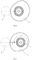
- the continuously variable valve lift mechanism 100 is located at the maximum lift position and may prepare for starting the engine. Specifically, as shown in Fig. 3 , the continuously variable valve lift mechanism 100 is configured such that at the maximum lift position, the resultant force F of the roller assembly of the continuously variable valve lift mechanism on the eccentric wheel has a direction passing through the axis of the eccentric shaft 3, so as to self lock the continuously variable valve lift mechanism 100 at the maximum lift position after self learning is successful.
- a pressure angle is greater than a friction angle for the profile of the eccentric wheel at the maximum lift, and the resultant force of the roller assembly on the eccentric wheel has the direction passing through the axis of the eccentric shaft 3.
- the eccentric wheel and the roller assembly are self locked, and the continuously variable valve lift mechanism 100 is self locked at the maximum lift position, such that the engine may be started smoothly, and particularly, the cold start may be performed smoothly.
- the method further includes: controlling an opening of the throttle valve to enable the vehicle to be started and travel. That is, after entering the limp mode, the continuously variable valve lift mechanism is self locked at the maximum lift position firstly, such that the engine may be started smoothly. Then, the opening of the throttle valve may be controlled by a driver, or the like, so as to control a load of the vehicle, and the driver may be facilitated to start the vehicle smoothly and drive the vehicle to a maintenance station for maintenance, which avoids the vehicle being incapable of traveling since the engine is unable to be started. That is, in the limp mode, by controlling the load through the throttle valve, the cold start, accelerating, decelerating, idling, or the like may be performed on the vehicle normally, and the vehicle may be guaranteed to be driven to a maintenance centre for maintenance.
- the continuously variable valve lift mechanism when the continuously variable valve lift mechanism fails and disables an automatic valve lift changing function, the continuously variable valve lift mechanism is controlled to enter the limp mode, forced to move to the maximum lift position, and self locked at the maximum lift position after reaching the maximum lift position, thereby enabling the vehicle to be started and travel smoothly, facilitating the driver to drive the vehicle to the maintenance centre for maintenance, and increasing the efficiency of maintenance.
- Fig. 5 is a structural block diagram of a control system for the continuously variable valve lift mechanism according to one embodiment of the present disclosure.
- the control system 500 for the continuously variable valve lift mechanism according to the embodiment of the present disclosure includes a mode switching module 510 and a drive module 520.
- the mode switching module 510 is configured to control the continuously variable valve lift mechanism to enter the limp mode when the continuously variable valve lift mechanism fails and disables the automatic valve lift changing function.
- the drive module 520 is configured to drive and force the continuously variable valve lift mechanism to move to the maximum lift position, and trigger the self locking function to self lock the continuously variable valve lift mechanism at the maximum lift position when the continuously variable valve lift mechanism reaches the maximum lift position.
- the failure of the continuously variable valve lift mechanism disabling the automatic valve lift changing function includes the failure of the electronic control component of the continuously variable valve lift mechanism and/or the failure of at least one phase in the three phase line of the electric motor.
- the continuously variable valve lift mechanism is configured such that at the maximum lift position, the resultant force of the roller assembly of the continuously variable valve lift mechanism on the eccentric wheel has the direction passing through the axis of the eccentric shaft, so as to self lock the continuously variable valve lift mechanism at the maximum lift position when the continuously variable valve lift mechanism reaches the maximum lift position in the limp mode.
- control system further includes: a control module (not shown in Fig. 5 ) configured to control the opening of the throttle valve to enable the vehicle to be started and travel after the continuously variable valve lift mechanism is self locked at the maximum lift position.
- a control module (not shown in Fig. 5 ) configured to control the opening of the throttle valve to enable the vehicle to be started and travel after the continuously variable valve lift mechanism is self locked at the maximum lift position.
- the continuously variable valve lift mechanism when the continuously variable valve lift mechanism fails and disables an automatic valve lift changing function, the continuously variable valve lift mechanism is controlled to enter the limp mode, forced to move to the maximum lift position, and self locked at the maximum lift position after reaching the maximum lift position, thereby enabling the vehicle to be started and travel smoothly, facilitating the driver to drive the vehicle to the maintenance centre for maintenance, and increasing the efficiency of maintenance.
- control system for the continuously variable valve lift mechanism is similar to a specific implementation of the control method for the continuously variable valve lift mechanism according to the embodiments of the present disclosure, and refers to the description of the method for details, which will not be repeated herein to reduce redundancy.
- an embodiment of the present disclosure discloses a vehicle provided with the control system for the continuously variable valve lift mechanism according to any one of the above-mentioned embodiments.
- the continuously variable valve lift mechanism fails and disables an automatic valve lift changing function
- the continuously variable valve lift mechanism is controlled to enter the limp mode, forced to move to the maximum lift position, and self locked at the maximum lift position after reaching the maximum lift position, thereby enabling the vehicle to be started and travel smoothly, facilitating the driver to drive the vehicle to the maintenance centre for maintenance, and increasing the efficiency of maintenance.
- an embodiment of the present disclosure discloses an apparatus including: one or a plurality of processors, a memory, and one or a plurality of programs stored in the memory.
- the one or the plurality of programs execute the control method for the continuously variable valve lift mechanism according to the above-mentioned embodiments of the present disclosure.
- the vehicle may be guaranteed to be started and travel smoothly when the continuously variable valve lift mechanism fails and disables the automatic valve lift changing function.
- an embodiment of the present disclosure discloses a nonvolatile computer storage medium configured to store one or a plurality of programs, and when executed by one apparatus, the one or the plurality of programs enable the apparatus to execute the control method for the continuously variable valve lift mechanism according to the above-mentioned embodiments of the present disclosure.
- the vehicle may be guaranteed to be started and travel smoothly when the continuously variable valve lift mechanism fails and disables the automatic valve lift changing function.
Landscapes
- Engineering & Computer Science (AREA)
- Mechanical Engineering (AREA)
- General Engineering & Computer Science (AREA)
- Chemical & Material Sciences (AREA)
- Combustion & Propulsion (AREA)
- Valve Device For Special Equipments (AREA)
- Output Control And Ontrol Of Special Type Engine (AREA)
Abstract
Description
- The present application claims priority to Chinese Patent Application Serial No.
201710437393.6 - The present disclosure relates to the technical field of automobiles, and particularly to a control method and a control system for a continuously variable valve lift mechanism and a vehicle.
- With the increasingly serious environmental problem, low emission and environmental protection have become preconditions for an engine to enter the market. A load of the traditional gasoline engine is changed by changing a throttle valve to regulate air inflow. Under a small load condition, the throttle valve has a small opening, there exists a quite large vacuum degree behind the throttle valve, and a pumping loss is great in the process of breathing of the engine, which is an important reason why the gasoline engine works less efficiently than a diesel engine. To increase the efficiency of the engine, a continuously variable valve lift technology is proposed. In a related art, since a continuously variable valve lift mechanism has many electronic control components, a failure of the electronic control components may disable an automatic valve lift changing function of the continuously variable valve lift mechanism, and a vehicle fails to be started sometimes. Particularly, cold start is not able to be performed smoothly, and the vehicle breaks down, is unable to travel, and required to be trailed to a maintenance station by a trailer for maintenance, which affects the efficiency of maintaining the vehicle.
- The present disclosure is intended to propose a control method for a continuously variable valve lift mechanism, and with the method, a vehicle may be guaranteed to be started and travel smoothly when the continuously variable valve lift mechanism fails and disables an automatic valve lift changing function.
- To achieve the above-mentioned objective, the present disclosure provides the technical solution as follows.
- A control method for a continuously variable valve lift mechanism includes: controlling a continuously variable valve lift mechanism to enter a limp mode when the continuously variable valve lift mechanism fails and disables an automatic valve lift changing function; driving and forcing the continuously variable valve lift mechanism to move to a maximum lift position; and triggering a self locking function to self lock the continuously variable valve lift mechanism at the maximum lift position when the continuously variable valve lift mechanism reaches the maximum lift position.
- Further, the failure of the continuously variable valve lift mechanism disabling the automatic valve lift changing function includes: a failure of an electronic control component of the continuously variable valve lift mechanism; and/or a failure of at least one phase in a three phase line of an electric motor.
- Further, the continuously variable valve lift mechanism is configured such that at the maximum lift position, a resultant force of a roller assembly of the continuously variable valve lift mechanism on an eccentric wheel has a direction passing through an axis of an eccentric shaft, so as to self lock the continuously variable valve lift mechanism at the maximum lift position when the continuously variable valve lift mechanism reaches the maximum lift position in the limp mode.
- Further, after the continuously variable valve lift mechanism is self locked at the maximum lift position, the method further includes: controlling an opening of a throttle valve to enable the vehicle to be started and travel.
- Compared with the related art, the control method for the continuously variable valve lift mechanism according to the present disclosure has the following advantages.
- With the control method for the continuously variable valve lift mechanism according to the embodiments of the present disclosure, when the continuously variable valve lift mechanism fails and disables an automatic valve lift changing function, the continuously variable valve lift mechanism is controlled to enter the limp mode, forced to move to the maximum lift position, and self locked at the maximum lift position after reaching the maximum lift position, thereby enabling the vehicle to be started and travel smoothly, facilitating a driver to drive the vehicle to a maintenance centre for maintenance, and increasing the efficiency of maintenance.
- A second objective of the present disclosure is to propose a control system for a continuously variable valve lift mechanism, and with the system, a vehicle may be guaranteed to be started and travel smoothly when the continuously variable valve lift mechanism fails and disables an automatic valve lift changing function.
- To achieve the above-mentioned objective, the present disclosure provides the technical solution as follows.
- A control system for a continuously variable valve lift mechanism includes: a mode switching module configured to control a continuously variable valve lift mechanism to enter a limp mode when the continuously variable valve lift mechanism fails and disables an automatic valve lift changing function; and a drive module configured to drive and force the continuously variable valve lift mechanism to move to a maximum lift position, and trigger a self locking function to self lock the continuously variable valve lift mechanism at the maximum lift position when the continuously variable valve lift mechanism reaches the maximum lift position.
- Further, the failure of the continuously variable valve lift mechanism disabling the automatic valve lift changing function includes a failure of an electronic control component of the continuously variable valve lift mechanism; and/or a failure of at least one phase in a three phase line of an electric motor.
- Further, the continuously variable valve lift mechanism is configured such that at the maximum lift position, a resultant force of a roller assembly of the continuously variable valve lift mechanism on an eccentric wheel has a direction passing through an axis of an eccentric shaft, so as to self lock the continuously variable valve lift mechanism at the maximum lift position when the continuously variable valve lift mechanism reaches the maximum lift position in the limp mode.
- Further, the control system further includes: a control module configured to control an opening of a throttle valve to enable the vehicle to be started and travel after the continuously variable valve lift mechanism is self locked at the maximum lift position.
- The control system and the control method for the continuously variable valve lift mechanism have the same advantages relative to the related art, which will not be elaborated herein.
- A third objective of the present disclosure is to propose a vehicle, and with the vehicle, the vehicle may be guaranteed to be started and travel smoothly when a continuously variable valve lift mechanism fails and disables an automatic valve lift changing function.
- To achieve the above-mentioned objective, the present disclosure provides the technical solution as follows.
- A vehicle is provided with the control system for the continuously variable valve lift mechanism according to any of the above-mentioned embodiments.
- The vehicle and the above-mentioned control system for the continuously variable valve lift mechanism have the same advantages relative to the related art, which will not be elaborated herein.
- A fourth objective of the present disclosure is to propose an apparatus, and with the apparatus, a vehicle may be guaranteed to be started and travel smoothly when a continuously variable valve lift mechanism fails and disables an automatic valve lift changing function.
- To achieve the above-mentioned objective, the present disclosure provides the technical solution as follows.
- An apparatus includes: one or a plurality of processors, a memory, and one or a plurality of programs stored in the memory. When executed by the one or the plurality of processors, the one or the plurality of programs execute the control method for the continuously variable valve lift mechanism according to the above-mentioned embodiments of the present disclosure.
- The apparatus and the above-mentioned control method for the continuously variable valve lift mechanism have the same advantages relative to the related art, which will not be elaborated herein.
- A fifth objective of the present disclosure is to propose a nonvolatile computer storage medium, and with the nonvolatile computer storage medium, a vehicle may be guaranteed to be started and travel smoothly when a continuously variable valve lift mechanism fails and disables an automatic valve lift changing function.
- To achieve the above-mentioned objective, the present disclosure provides the technical solution as follows.
- A nonvolatile computer storage medium stores one or a plurality of programs. When executed by one apparatus, the one or the plurality of programs enable the apparatus to execute the control method for the continuously variable valve lift mechanism according to the above-mentioned embodiments of the present disclosure.
- The nonvolatile computer storage medium and the above-mentioned control method for the continuously variable valve lift mechanism have the same advantages relative to the related art, which will not be elaborated herein.
- The accompanying drawings which constitute a part of the present disclosure serve to provide a further understanding of the present disclosure, and exemplary embodiments of the present disclosure and explanation thereof are used for interpreting the present disclosure, without limiting the present disclosure improperly. In the drawings:
-
Fig. 1 is a schematic structural diagram of a continuously variable valve lift mechanism according to an embodiment of the present disclosure; -
Fig. 2 is a schematic structural diagram of an eccentric shaft at a minimum lift position according to an embodiment of the present disclosure; -
Fig. 3 is a schematic structural diagram of an eccentric shaft at a maximum lift position according to an embodiment of the present disclosure; -
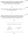
Fig. 4 is a flow chart of a control method for a continuously variable valve lift mechanism according to an embodiment of the present disclosure; and -
Fig. 5 is a structural block diagram of a control system for a continuously variable valve lift mechanism according to an embodiment of the present disclosure. - continuously variable
valve lift mechanism 100;camshaft 1; supportingbase 2;eccentric shaft 3;roller assembly 4;roller rocker 5;intermediate swing arm 6; outer regulatingscrew 7; intermediate swingarm pin shaft 8; inner regulatingscrew 9;fixed support 10; returningspring 11;valve 12; locating sleeve 13; locating pin 14; small camshaft cover 15; cylinder head 16; control system 500 for continuously variable valve lift mechanism; mode switching module 510;drive module 520. - It should be noted that the embodiments in the present disclosure and features in the embodiments may be combined mutually in the case of no conflicts.
- The present disclosure will be described in detail below with reference to the drawings in conjunction with the embodiments.
- As shown in
Fig. 1 , a continuously variablevalve lift mechanism 100 may include acamshaft 1, a supportingbase 2, aneccentric shaft 3, aroller assembly 4, aroller rocker 5, anintermediate swing arm 6, an outer regulatingscrew 7, an intermediate swingarm pin shaft 8, an inner regulatingscrew 9, afixed support 10, a returningspring 11, avalve 12, a locating sleeve 13, a locating pin 14, a small camshaft cover 15, a cylinder head 16 and an eccentric shaft driving device. - The
camshaft 1, theeccentric shaft 3 and thefixed support 10 are all mounted on the supportingbase 2, thecamshaft 1 and theeccentric shaft 3 may rotate freely, and the supportingbase 2 is mounted on the cylinder head 16. - The
camshaft 1 is connected with a crankshaft of an engine, for example, by chain transmission. Thecamshaft 1 rotates to drive theroller assembly 4, a roller of theintermediate swing arm 6 is in close contact with theroller assembly 4 by means of the returningspring 11, and theroller assembly 4 transmits movement to theintermediate swing arm 6, which drives theroller rocker 5, thereby opening or closing thevalve 12. - The eccentric shaft driving device is coupled to the
eccentric shaft 3 dynamically, so as to control theeccentric shaft 3 to rotate clockwise or anticlockwise. The eccentric shaft driving device may be configured as a control electric motor, and an output shaft of the control electric motor may be configured as a worm. Theeccentric shaft 3 may be fixedly connected with a worm gear, and the worm is engaged with the worm gear, such that the control electric motor is coupled to theeccentric shaft 3 dynamically. - The
eccentric shaft 3 is fixedly connected with an eccentric wheel, and when theeccentric shaft 3 rotates, the eccentric wheel of theeccentric shaft 3 drives theroller assembly 4 to change a contact point between theroller assembly 4 and the roller of theintermediate swing arm 6, thereby regulating a lift and an opening duration of the valve. - The
intermediate swing arm 6 is mounted on thefixed support 10 by means of the intermediate swingarm pin shaft 8, and the position of the intermediate swingarm pin shaft 8 may be fixed or regulated by the outer regulatingscrew 7 and the inner regulatingscrew 9, and changed by rotating the outer regulatingscrew 7 or the inner regulatingscrew 9, thereby regulating a center of rotation of theintermediate swing arm 6. Twointermediate swing arms 6 may be mounted to eachfixed support 10, and thefixed support 10 is mounted on the supportingbase 2. - A control method for the continuously variable valve lift mechanism according to an embodiment of the present disclosure will be described below.
- The two
valves 12 of the continuously variablevalve lift mechanism 100 for the same cylinder may correspond to the eccentric wheels with different profiles. That is, the twovalves 12 for the same cylinder may have the lifts which are not synchronous completely. - Firstly, it should be noted that the control method for the continuously variable valve lift mechanism according to the embodiment of the present disclosure is a control strategy for the continuously variable valve lift mechanism in the case of a failure of the continuously variable valve lift mechanism. Without failures, the continuously variable valve lift mechanism may be controlled according to a conventional control strategy. As shown in
Figs. 1 to 3 , for example, when the continuously variable valve lift mechanism does not fail, spring forces of the returningspring 11 in contact with an intermediate push rod and a valve spring of a valve mechanism act on the intermediate push rod which comes into contact with theroller assembly 4, and a resultant force of the spring forces is transmitted to theroller assembly 4. Theroller assembly 4 receives an acting force of thecamshaft 1 at the same time. A resultant force received by theroller assembly 4 is transmitted onto the eccentric wheel of theeccentric shaft 3, and rotates the eccentric wheel to a small lift. A position of theeccentric shaft 3 is controlled by the control electric motor of the continuously variable valve lift mechanism (CVVL), and thus, a position of the eccentric wheel may be controlled under normal circumstances. - However, in some cases, for example, in the case where the continuously variable valve lift mechanism fails and disables an automatic valve lift changing function, the position of the eccentric wheel is not controlled actively, and if the continuously variable valve lift mechanism is not located nearby the maximum lift position, the eccentric wheel will rotate automatically to the small lift under the action of the received resultant force. If the eccentric wheel stays at the small lift position, cold start of the engine could not be performed.
- It should be noted that the failure of the continuously variable valve lift mechanism disabling the automatic valve lift changing function includes, but not limited to, a failure of an electronic control component of the continuously variable valve lift mechanism and/or a failure of at least one phase in a three phase line of the electric motor, i.e., the failure of the electronic control component of the continuously variable valve lift mechanism (CVVL) and/or the failure of a certain phase in the three phase line of the electric motor.
- Thus, with the control method for the continuously variable valve lift mechanism according to the embodiment of the present disclosure, in the case of failure of the continuously variable valve lift mechanism, a vehicle may be guaranteed to be started successfully and travel.
- As shown in
Fig. 4 , the control method for the continuously variable valve lift mechanism according to one embodiment of the present disclosure includes the following steps. - S401: controlling a continuously variable valve lift mechanism to enter a limp mode when the continuously variable valve lift mechanism fails and disables an automatic valve lift changing function. The failure of the continuously variable valve lift mechanism disabling the automatic valve lift changing function includes the failure of the electronic control component of the continuously variable valve lift mechanism and/or the failure of at least one phase in the three phase line of the electric motor.
- That is, the failure is present in the electronic control component of the continuously variable valve lift mechanism and a certain phase in the three phase line of the electric motor, and the conventional control strategy for the continuously variable valve lift mechanism is disabled. At this point, the limp mode of the continuously variable valve lift mechanism will be triggered.
- S402: driving and forcing the continuously variable valve lift mechanism to move to the maximum lift position. After the limp mode of the continuously variable valve lift mechanism is triggered, the electric motor will force and drive the continuously variable valve lift mechanism to move to the maximum lift position.
- S403: triggering a self locking function to self lock the continuously variable valve lift mechanism at the maximum lift position when the continuously variable valve lift mechanism reaches the maximum lift position.
- The continuously variable valve lift mechanism is configured such that at the maximum lift position, the resultant force of the roller assembly of the continuously variable valve lift mechanism on the eccentric wheel has a direction passing through an axis of the eccentric shaft, so as to self lock the continuously variable valve lift mechanism at the maximum lift position when the continuously variable valve lift mechanism reaches the maximum lift position in the limp mode.
- The continuously variable
valve lift mechanism 100 is located at the maximum lift position and may prepare for starting the engine. Specifically, as shown inFig. 3 , the continuously variablevalve lift mechanism 100 is configured such that at the maximum lift position, the resultant force F of the roller assembly of the continuously variable valve lift mechanism on the eccentric wheel has a direction passing through the axis of theeccentric shaft 3, so as to self lock the continuously variablevalve lift mechanism 100 at the maximum lift position after self learning is successful. A pressure angle is greater than a friction angle for the profile of the eccentric wheel at the maximum lift, and the resultant force of the roller assembly on the eccentric wheel has the direction passing through the axis of theeccentric shaft 3. Thus, the eccentric wheel and the roller assembly are self locked, and the continuously variablevalve lift mechanism 100 is self locked at the maximum lift position, such that the engine may be started smoothly, and particularly, the cold start may be performed smoothly. - Further, after the continuously variable valve lift mechanism is self locked at the maximum lift position, the method further includes: controlling an opening of the throttle valve to enable the vehicle to be started and travel. That is, after entering the limp mode, the continuously variable valve lift mechanism is self locked at the maximum lift position firstly, such that the engine may be started smoothly. Then, the opening of the throttle valve may be controlled by a driver, or the like, so as to control a load of the vehicle, and the driver may be facilitated to start the vehicle smoothly and drive the vehicle to a maintenance station for maintenance, which avoids the vehicle being incapable of traveling since the engine is unable to be started. That is, in the limp mode, by controlling the load through the throttle valve, the cold start, accelerating, decelerating, idling, or the like may be performed on the vehicle normally, and the vehicle may be guaranteed to be driven to a maintenance centre for maintenance.
- With the control method for the continuously variable valve lift mechanism according to the embodiments of the present disclosure, when the continuously variable valve lift mechanism fails and disables an automatic valve lift changing function, the continuously variable valve lift mechanism is controlled to enter the limp mode, forced to move to the maximum lift position, and self locked at the maximum lift position after reaching the maximum lift position, thereby enabling the vehicle to be started and travel smoothly, facilitating the driver to drive the vehicle to the maintenance centre for maintenance, and increasing the efficiency of maintenance.
-
Fig. 5 is a structural block diagram of a control system for the continuously variable valve lift mechanism according to one embodiment of the present disclosure. As shown inFig. 5 , the control system 500 for the continuously variable valve lift mechanism according to the embodiment of the present disclosure includes a mode switching module 510 and adrive module 520. - The mode switching module 510 is configured to control the continuously variable valve lift mechanism to enter the limp mode when the continuously variable valve lift mechanism fails and disables the automatic valve lift changing function. The
drive module 520 is configured to drive and force the continuously variable valve lift mechanism to move to the maximum lift position, and trigger the self locking function to self lock the continuously variable valve lift mechanism at the maximum lift position when the continuously variable valve lift mechanism reaches the maximum lift position. - In one embodiment of the present disclosure, the failure of the continuously variable valve lift mechanism disabling the automatic valve lift changing function includes the failure of the electronic control component of the continuously variable valve lift mechanism and/or the failure of at least one phase in the three phase line of the electric motor.
- In one embodiment of the present disclosure, the continuously variable valve lift mechanism is configured such that at the maximum lift position, the resultant force of the roller assembly of the continuously variable valve lift mechanism on the eccentric wheel has the direction passing through the axis of the eccentric shaft, so as to self lock the continuously variable valve lift mechanism at the maximum lift position when the continuously variable valve lift mechanism reaches the maximum lift position in the limp mode.
- In one embodiment of the present disclosure, the control system further includes: a control module (not shown in
Fig. 5 ) configured to control the opening of the throttle valve to enable the vehicle to be started and travel after the continuously variable valve lift mechanism is self locked at the maximum lift position. - With the control system for the continuously variable valve lift mechanism according to the embodiments of the present disclosure, when the continuously variable valve lift mechanism fails and disables an automatic valve lift changing function, the continuously variable valve lift mechanism is controlled to enter the limp mode, forced to move to the maximum lift position, and self locked at the maximum lift position after reaching the maximum lift position, thereby enabling the vehicle to be started and travel smoothly, facilitating the driver to drive the vehicle to the maintenance centre for maintenance, and increasing the efficiency of maintenance.
- It should be noted that a specific implementation of the control system for the continuously variable valve lift mechanism according to the embodiments of the present disclosure is similar to a specific implementation of the control method for the continuously variable valve lift mechanism according to the embodiments of the present disclosure, and refers to the description of the method for details, which will not be repeated herein to reduce redundancy.
- Further, an embodiment of the present disclosure discloses a vehicle provided with the control system for the continuously variable valve lift mechanism according to any one of the above-mentioned embodiments. With the vehicle, when the continuously variable valve lift mechanism fails and disables an automatic valve lift changing function, the continuously variable valve lift mechanism is controlled to enter the limp mode, forced to move to the maximum lift position, and self locked at the maximum lift position after reaching the maximum lift position, thereby enabling the vehicle to be started and travel smoothly, facilitating the driver to drive the vehicle to the maintenance centre for maintenance, and increasing the efficiency of maintenance.
- In addition, other configurations and functions of the vehicle according to the above-mentioned embodiments of the present disclosure are known to a person skilled in the art, which will not be repeated herein to reduce redundancy.
- Further, an embodiment of the present disclosure discloses an apparatus including: one or a plurality of processors, a memory, and one or a plurality of programs stored in the memory. When executed by the one or the plurality of processors, the one or the plurality of programs execute the control method for the continuously variable valve lift mechanism according to the above-mentioned embodiments of the present disclosure. With the apparatus, the vehicle may be guaranteed to be started and travel smoothly when the continuously variable valve lift mechanism fails and disables the automatic valve lift changing function.
- Further, an embodiment of the present disclosure discloses a nonvolatile computer storage medium configured to store one or a plurality of programs, and when executed by one apparatus, the one or the plurality of programs enable the apparatus to execute the control method for the continuously variable valve lift mechanism according to the above-mentioned embodiments of the present disclosure. With the nonvolatile computer storage medium, the vehicle may be guaranteed to be started and travel smoothly when the continuously variable valve lift mechanism fails and disables the automatic valve lift changing function.
- The above are merely the preferred embodiments of the present disclosure and shall not be used to limit the present disclosure. Any modifications, equivalents and improvements made within the spirit and principle of the present disclosure shall fall within the protection scope of the present disclosure.
Claims (11)
- A control method for a continuously variable valve lift mechanism, comprising:controlling a continuously variable valve lift mechanism to enter a limp mode when the continuously variable valve lift mechanism fails and disables an automatic valve lift changing function;driving and forcing the continuously variable valve lift mechanism to move to a maximum lift position; andtriggering a self locking function to self lock the continuously variable valve lift mechanism at the maximum lift position when the continuously variable valve lift mechanism reaches the maximum lift position.
- The control method according to claim 1, wherein the failure of the continuously variable valve lift mechanism disabling the automatic valve lift changing function comprises:a failure of an electronic control component of the continuously variable valve lift mechanism; and/ora failure of at least one phase in a three phase line of an electric motor.
- The control method according to claim 1, wherein the continuously variable valve lift mechanism is configured such that at the maximum lift position, a resultant force of a roller assembly the continuously variable valve lift mechanism on an eccentric wheel has a direction passing through an axis of an eccentric shaft, so as to self lock the continuously variable valve lift mechanism at the maximum lift position when the continuously variable valve lift mechanism reaches the maximum lift position in the limp mode.
- The control method according to any one of claims 1-3, wherein after the continuously variable valve lift mechanism is self locked at the maximum lift position, the method further comprises: controlling an opening of a throttle valve to enable a vehicle to be started and travel.
- A control system for a continuously variable valve lift mechanism, comprising:a mode switching module configured to control a continuously variable valve lift mechanism to enter a limp mode when the continuously variable valve lift mechanism fails and disables an automatic valve lift changing function; anda drive module configured to drive and force the continuously variable valve lift mechanism to move to a maximum lift position, and trigger a self locking function to self lock the continuously variable valve lift mechanism at the maximum lift position when the continuously variable valve lift mechanism reaches the maximum lift position.
- The control system according to claim 5, wherein the failure of the continuously variable valve lift mechanism disabling the automatic valve lift changing function comprises:a failure of an electronic control component of the continuously variable valve lift mechanism; and/ora failure of at least one phase in a three phase line of an electric motor.
- The control system according to claim 5, wherein the continuously variable valve lift mechanism is configured such that at the maximum lift position, a resultant force of a roller assembly thereof on an eccentric wheel has a direction passing through an axis of an eccentric shaft, so as to self lock the continuously variable valve lift mechanism at the maximum lift position when the continuously variable valve lift mechanism reaches the maximum lift position in the limp mode.
- The control system according to any one of claims 5-7, further comprising: a control module configured to control an opening of a throttle valve to enable a vehicle to be started and travel after the continuously variable valve lift mechanism is self locked at the maximum lift position.
- A vehicle, provided with a control system for a continuously variable valve lift mechanism according to any one of claims 5-8.
- An apparatus, comprising:one or a plurality of processors;a memory; andone or a plurality of programs stored in the memory, and configured to execute a control method for a continuously variable valve lift mechanism according to any one of claims 1-4 when executed by the one or the plurality of processors.
- A nonvolatile computer storage medium configured to store one or a plurality of programs, wherein when executed by one apparatus, the one or the plurality of programs enable the apparatus to execute a control method for a continuously variable valve lift mechanism according to any one of claims 1-4.
Applications Claiming Priority (2)
| Application Number | Priority Date | Filing Date | Title |
|---|---|---|---|
| CN201710437393.6A CN108223039B (en) | 2017-06-09 | 2017-06-09 | Control method, system and the vehicle of continuous variable valve lift mechanism |
| PCT/CN2018/090304 WO2018224020A1 (en) | 2017-06-09 | 2018-06-07 | Control method and system for continuously variable valve lift mechanism, and vehicle |
Publications (3)
| Publication Number | Publication Date |
|---|---|
| EP3636886A1 true EP3636886A1 (en) | 2020-04-15 |
| EP3636886A4 EP3636886A4 (en) | 2021-03-31 |
| EP3636886B1 EP3636886B1 (en) | 2023-10-25 |
Family
ID=62656663
Family Applications (1)
| Application Number | Title | Priority Date | Filing Date |
|---|---|---|---|
| EP18813824.2A Active EP3636886B1 (en) | 2017-06-09 | 2018-06-07 | Control method and system for continuously variable valve lift mechanism, and vehicle |
Country Status (5)
| Country | Link |
|---|---|
| US (1) | US11761360B2 (en) |
| EP (1) | EP3636886B1 (en) |
| CN (1) | CN108223039B (en) |
| RU (1) | RU2736675C1 (en) |
| WO (1) | WO2018224020A1 (en) |
Families Citing this family (1)
| Publication number | Priority date | Publication date | Assignee | Title |
|---|---|---|---|---|
| KR20210047132A (en) * | 2019-10-21 | 2021-04-29 | 현대자동차주식회사 | Method for Control To Establish CVVD Start Up and Continuous Variable Valve Duration System Thereof |
Family Cites Families (20)
| Publication number | Priority date | Publication date | Assignee | Title |
|---|---|---|---|---|
| SU151530A1 (en) * | 1961-12-09 | 1962-11-30 | И.Ф. Любечанский | The mechanism of regulation of the phases and the law of valve lift of the gas distribution system of internal combustion engines |
| US6595172B2 (en) * | 2001-05-14 | 2003-07-22 | Delphi Technologies, Inc. | Variable valve actuator assembly having a secondary actuator |
| AU2003221686A1 (en) * | 2002-04-08 | 2003-10-27 | Diesel Engine Retarders, Inc. | Compact lost motion system for variable valve actuation |
| JP2004183591A (en) * | 2002-12-05 | 2004-07-02 | Toyota Motor Corp | Control device for internal combustion engine having variable valve mechanism |
| JP4489380B2 (en) * | 2003-06-25 | 2010-06-23 | 日立オートモティブシステムズ株式会社 | Fail-safe control device for internal combustion engine with variable valve mechanism |
| JP4266170B2 (en) * | 2004-02-02 | 2009-05-20 | 株式会社日立製作所 | Air quantity control device for internal combustion engine |
| JP2005214168A (en) * | 2004-02-02 | 2005-08-11 | Hitachi Ltd | Variable valve control device for internal combustion engine |
| JP4198073B2 (en) * | 2004-02-06 | 2008-12-17 | 株式会社日立製作所 | Control device for internal combustion engine |
| JP4483637B2 (en) | 2005-03-15 | 2010-06-16 | 日産自動車株式会社 | Internal combustion engine |
| RU2298108C2 (en) * | 2005-05-04 | 2007-04-27 | Закрытое акционерное общество "Торговый дом "Вертолеты-МИ" | Timing gear internal combustion engine |
| JP4265608B2 (en) * | 2006-01-17 | 2009-05-20 | トヨタ自動車株式会社 | Control device for variable valve mechanism |
| JP4858235B2 (en) * | 2007-03-02 | 2012-01-18 | トヨタ自動車株式会社 | Control device for variable valve mechanism |
| JP2008255851A (en) * | 2007-04-03 | 2008-10-23 | Toyota Motor Corp | Internal combustion engine with variable valve mechanism |
| JP2009250029A (en) * | 2008-04-01 | 2009-10-29 | Honda Motor Co Ltd | Control device of internal combustion engine |
| JP2010112197A (en) * | 2008-11-04 | 2010-05-20 | Honda Motor Co Ltd | Internal combustion engine |
| CN101749065B (en) * | 2009-12-24 | 2012-10-24 | 奇瑞汽车股份有限公司 | Variable valve timing (VVT) adjusting method of engine and device |
| CN202611784U (en) * | 2011-11-02 | 2012-12-19 | 德尔福技术有限公司 | Continuous variable valve lift system with default mechanism |
| US8584631B2 (en) * | 2011-11-02 | 2013-11-19 | Delphi Technologies, Inc. | Continuously variable valve lift system with default mechanism |
| CN104153839B (en) * | 2014-08-29 | 2017-01-11 | 长城汽车股份有限公司 | Method for self-inspection of continuously variable valve lift mechanism |
| CN204436505U (en) * | 2015-02-11 | 2015-07-01 | 长城汽车股份有限公司 | Variable air valve lift range mechanism |
-
2017
- 2017-06-09 CN CN201710437393.6A patent/CN108223039B/en active Active
-
2018
- 2018-06-07 US US16/620,596 patent/US11761360B2/en active Active
- 2018-06-07 RU RU2020100110A patent/RU2736675C1/en active
- 2018-06-07 EP EP18813824.2A patent/EP3636886B1/en active Active
- 2018-06-07 WO PCT/CN2018/090304 patent/WO2018224020A1/en not_active Ceased
Also Published As
| Publication number | Publication date |
|---|---|
| WO2018224020A1 (en) | 2018-12-13 |
| EP3636886A4 (en) | 2021-03-31 |
| EP3636886B1 (en) | 2023-10-25 |
| US20200095909A1 (en) | 2020-03-26 |
| CN108223039A (en) | 2018-06-29 |
| RU2736675C1 (en) | 2020-11-19 |
| CN108223039B (en) | 2019-11-01 |
| US11761360B2 (en) | 2023-09-19 |
Similar Documents
| Publication | Publication Date | Title |
|---|---|---|
| JP4749981B2 (en) | Variable valve operating device for internal combustion engine | |
| CN101379283B (en) | Control device and control method for internal combustion engine | |
| JP5662264B2 (en) | Variable valve operating device for internal combustion engine | |
| US20150369199A1 (en) | Automatic stop/restart control system for an internal combustion engine and variable valve actuating apparatus | |
| KR101832300B1 (en) | Vehicle control apparatus and vehicle control method | |
| EP3392476B1 (en) | Continuously variable valve lift system and automobile | |
| RU2736674C1 (en) | Method of stepless valve lifting mechanism control, device for implementation of such control method and nonvolatile computer-readable data medium for implementation of such control method | |
| JP6073285B2 (en) | Control device | |
| US9518545B2 (en) | Method and device for operating an internal combustion engine | |
| EP3636886B1 (en) | Control method and system for continuously variable valve lift mechanism, and vehicle | |
| US6595172B2 (en) | Variable valve actuator assembly having a secondary actuator | |
| EP3163055A1 (en) | Control device for compression ratio variable internal combustion engine | |
| EP3636887B1 (en) | Valve mechanism, engine, and vehicle | |
| JP2007285292A (en) | Valve drive device | |
| US12460594B2 (en) | Shutdown control of internal combustion engine comprising lost motion component | |
| US11162392B2 (en) | Valve operating device, in particular for an internal combustion engine | |
| JP2855889B2 (en) | Control device for internal combustion engine | |
| JP4941354B2 (en) | Engine start control device and engine start control method | |
| JP5516432B2 (en) | Variable valve operating apparatus for internal combustion engine and internal combustion engine provided with the same | |
| CN118974393A (en) | Method and system for standardizing the position of a piston | |
| JP2009144687A (en) | Variable valve operating device for internal combustion engine | |
| TWI586889B (en) | Engine system and straddled vehicle | |
| JP2007298046A (en) | Variable valve operating apparatus for internal combustion engine and control mechanism used therefor |
Legal Events
| Date | Code | Title | Description |
|---|---|---|---|
| STAA | Information on the status of an ep patent application or granted ep patent |
Free format text: STATUS: THE INTERNATIONAL PUBLICATION HAS BEEN MADE |
|
| PUAI | Public reference made under article 153(3) epc to a published international application that has entered the european phase |
Free format text: ORIGINAL CODE: 0009012 |
|
| STAA | Information on the status of an ep patent application or granted ep patent |
Free format text: STATUS: REQUEST FOR EXAMINATION WAS MADE |
|
| 17P | Request for examination filed |
Effective date: 20200108 |
|
| AK | Designated contracting states |
Kind code of ref document: A1 Designated state(s): AL AT BE BG CH CY CZ DE DK EE ES FI FR GB GR HR HU IE IS IT LI LT LU LV MC MK MT NL NO PL PT RO RS SE SI SK SM TR |
|
| A4 | Supplementary search report drawn up and despatched |
Effective date: 20210225 |
|
| RIC1 | Information provided on ipc code assigned before grant |
Ipc: F01L 1/24 20060101ALI20210219BHEP Ipc: F01L 1/18 20060101ALI20210219BHEP Ipc: F01L 1/34 20060101AFI20210219BHEP Ipc: F01L 13/00 20060101ALI20210219BHEP Ipc: F02D 13/02 20060101ALI20210219BHEP Ipc: F02D 41/22 20060101ALI20210219BHEP |
|
| GRAP | Despatch of communication of intention to grant a patent |
Free format text: ORIGINAL CODE: EPIDOSNIGR1 |
|
| STAA | Information on the status of an ep patent application or granted ep patent |
Free format text: STATUS: GRANT OF PATENT IS INTENDED |
|
| INTG | Intention to grant announced |
Effective date: 20230616 |
|
| GRAS | Grant fee paid |
Free format text: ORIGINAL CODE: EPIDOSNIGR3 |
|
| GRAA | (expected) grant |
Free format text: ORIGINAL CODE: 0009210 |
|
| STAA | Information on the status of an ep patent application or granted ep patent |
Free format text: STATUS: THE PATENT HAS BEEN GRANTED |
|
| P01 | Opt-out of the competence of the unified patent court (upc) registered |
Effective date: 20230817 |
|
| AK | Designated contracting states |
Kind code of ref document: B1 Designated state(s): AL AT BE BG CH CY CZ DE DK EE ES FI FR GB GR HR HU IE IS IT LI LT LU LV MC MK MT NL NO PL PT RO RS SE SI SK SM TR |
|
| REG | Reference to a national code |
Ref country code: GB Ref legal event code: FG4D |
|
| REG | Reference to a national code |
Ref country code: CH Ref legal event code: EP |
|
| REG | Reference to a national code |
Ref country code: DE Ref legal event code: R096 Ref document number: 602018060073 Country of ref document: DE |
|
| REG | Reference to a national code |
Ref country code: IE Ref legal event code: FG4D |
|
| REG | Reference to a national code |
Ref country code: LT Ref legal event code: MG9D |
|
| REG | Reference to a national code |
Ref country code: NL Ref legal event code: MP Effective date: 20231025 |
|
| REG | Reference to a national code |
Ref country code: AT Ref legal event code: MK05 Ref document number: 1624867 Country of ref document: AT Kind code of ref document: T Effective date: 20231025 |
|
| PG25 | Lapsed in a contracting state [announced via postgrant information from national office to epo] |
Ref country code: NL Free format text: LAPSE BECAUSE OF FAILURE TO SUBMIT A TRANSLATION OF THE DESCRIPTION OR TO PAY THE FEE WITHIN THE PRESCRIBED TIME-LIMIT Effective date: 20231025 |
|
| PG25 | Lapsed in a contracting state [announced via postgrant information from national office to epo] |
Ref country code: GR Free format text: LAPSE BECAUSE OF FAILURE TO SUBMIT A TRANSLATION OF THE DESCRIPTION OR TO PAY THE FEE WITHIN THE PRESCRIBED TIME-LIMIT Effective date: 20240126 |
|
| PG25 | Lapsed in a contracting state [announced via postgrant information from national office to epo] |
Ref country code: IS Free format text: LAPSE BECAUSE OF FAILURE TO SUBMIT A TRANSLATION OF THE DESCRIPTION OR TO PAY THE FEE WITHIN THE PRESCRIBED TIME-LIMIT Effective date: 20240225 |
|
| PG25 | Lapsed in a contracting state [announced via postgrant information from national office to epo] |
Ref country code: LT Free format text: LAPSE BECAUSE OF FAILURE TO SUBMIT A TRANSLATION OF THE DESCRIPTION OR TO PAY THE FEE WITHIN THE PRESCRIBED TIME-LIMIT Effective date: 20231025 |
|
| PG25 | Lapsed in a contracting state [announced via postgrant information from national office to epo] |
Ref country code: AT Free format text: LAPSE BECAUSE OF FAILURE TO SUBMIT A TRANSLATION OF THE DESCRIPTION OR TO PAY THE FEE WITHIN THE PRESCRIBED TIME-LIMIT Effective date: 20231025 |
|
| PG25 | Lapsed in a contracting state [announced via postgrant information from national office to epo] |
Ref country code: ES Free format text: LAPSE BECAUSE OF FAILURE TO SUBMIT A TRANSLATION OF THE DESCRIPTION OR TO PAY THE FEE WITHIN THE PRESCRIBED TIME-LIMIT Effective date: 20231025 |
|
| PG25 | Lapsed in a contracting state [announced via postgrant information from national office to epo] |
Ref country code: LT Free format text: LAPSE BECAUSE OF FAILURE TO SUBMIT A TRANSLATION OF THE DESCRIPTION OR TO PAY THE FEE WITHIN THE PRESCRIBED TIME-LIMIT Effective date: 20231025 Ref country code: IS Free format text: LAPSE BECAUSE OF FAILURE TO SUBMIT A TRANSLATION OF THE DESCRIPTION OR TO PAY THE FEE WITHIN THE PRESCRIBED TIME-LIMIT Effective date: 20240225 Ref country code: GR Free format text: LAPSE BECAUSE OF FAILURE TO SUBMIT A TRANSLATION OF THE DESCRIPTION OR TO PAY THE FEE WITHIN THE PRESCRIBED TIME-LIMIT Effective date: 20240126 Ref country code: ES Free format text: LAPSE BECAUSE OF FAILURE TO SUBMIT A TRANSLATION OF THE DESCRIPTION OR TO PAY THE FEE WITHIN THE PRESCRIBED TIME-LIMIT Effective date: 20231025 Ref country code: BG Free format text: LAPSE BECAUSE OF FAILURE TO SUBMIT A TRANSLATION OF THE DESCRIPTION OR TO PAY THE FEE WITHIN THE PRESCRIBED TIME-LIMIT Effective date: 20240125 Ref country code: AT Free format text: LAPSE BECAUSE OF FAILURE TO SUBMIT A TRANSLATION OF THE DESCRIPTION OR TO PAY THE FEE WITHIN THE PRESCRIBED TIME-LIMIT Effective date: 20231025 Ref country code: PT Free format text: LAPSE BECAUSE OF FAILURE TO SUBMIT A TRANSLATION OF THE DESCRIPTION OR TO PAY THE FEE WITHIN THE PRESCRIBED TIME-LIMIT Effective date: 20240226 |
|
| PG25 | Lapsed in a contracting state [announced via postgrant information from national office to epo] |
Ref country code: SE Free format text: LAPSE BECAUSE OF FAILURE TO SUBMIT A TRANSLATION OF THE DESCRIPTION OR TO PAY THE FEE WITHIN THE PRESCRIBED TIME-LIMIT Effective date: 20231025 Ref country code: RS Free format text: LAPSE BECAUSE OF FAILURE TO SUBMIT A TRANSLATION OF THE DESCRIPTION OR TO PAY THE FEE WITHIN THE PRESCRIBED TIME-LIMIT Effective date: 20231025 Ref country code: PL Free format text: LAPSE BECAUSE OF FAILURE TO SUBMIT A TRANSLATION OF THE DESCRIPTION OR TO PAY THE FEE WITHIN THE PRESCRIBED TIME-LIMIT Effective date: 20231025 Ref country code: NO Free format text: LAPSE BECAUSE OF FAILURE TO SUBMIT A TRANSLATION OF THE DESCRIPTION OR TO PAY THE FEE WITHIN THE PRESCRIBED TIME-LIMIT Effective date: 20240125 Ref country code: LV Free format text: LAPSE BECAUSE OF FAILURE TO SUBMIT A TRANSLATION OF THE DESCRIPTION OR TO PAY THE FEE WITHIN THE PRESCRIBED TIME-LIMIT Effective date: 20231025 Ref country code: HR Free format text: LAPSE BECAUSE OF FAILURE TO SUBMIT A TRANSLATION OF THE DESCRIPTION OR TO PAY THE FEE WITHIN THE PRESCRIBED TIME-LIMIT Effective date: 20231025 |
|
| PG25 | Lapsed in a contracting state [announced via postgrant information from national office to epo] |
Ref country code: DK Free format text: LAPSE BECAUSE OF FAILURE TO SUBMIT A TRANSLATION OF THE DESCRIPTION OR TO PAY THE FEE WITHIN THE PRESCRIBED TIME-LIMIT Effective date: 20231025 |
|
| PG25 | Lapsed in a contracting state [announced via postgrant information from national office to epo] |
Ref country code: CZ Free format text: LAPSE BECAUSE OF FAILURE TO SUBMIT A TRANSLATION OF THE DESCRIPTION OR TO PAY THE FEE WITHIN THE PRESCRIBED TIME-LIMIT Effective date: 20231025 |
|
| REG | Reference to a national code |
Ref country code: DE Ref legal event code: R097 Ref document number: 602018060073 Country of ref document: DE |
|
| PG25 | Lapsed in a contracting state [announced via postgrant information from national office to epo] |
Ref country code: SK Free format text: LAPSE BECAUSE OF FAILURE TO SUBMIT A TRANSLATION OF THE DESCRIPTION OR TO PAY THE FEE WITHIN THE PRESCRIBED TIME-LIMIT Effective date: 20231025 |
|
| PG25 | Lapsed in a contracting state [announced via postgrant information from national office to epo] |
Ref country code: SM Free format text: LAPSE BECAUSE OF FAILURE TO SUBMIT A TRANSLATION OF THE DESCRIPTION OR TO PAY THE FEE WITHIN THE PRESCRIBED TIME-LIMIT Effective date: 20231025 Ref country code: SK Free format text: LAPSE BECAUSE OF FAILURE TO SUBMIT A TRANSLATION OF THE DESCRIPTION OR TO PAY THE FEE WITHIN THE PRESCRIBED TIME-LIMIT Effective date: 20231025 Ref country code: RO Free format text: LAPSE BECAUSE OF FAILURE TO SUBMIT A TRANSLATION OF THE DESCRIPTION OR TO PAY THE FEE WITHIN THE PRESCRIBED TIME-LIMIT Effective date: 20231025 Ref country code: EE Free format text: LAPSE BECAUSE OF FAILURE TO SUBMIT A TRANSLATION OF THE DESCRIPTION OR TO PAY THE FEE WITHIN THE PRESCRIBED TIME-LIMIT Effective date: 20231025 Ref country code: DK Free format text: LAPSE BECAUSE OF FAILURE TO SUBMIT A TRANSLATION OF THE DESCRIPTION OR TO PAY THE FEE WITHIN THE PRESCRIBED TIME-LIMIT Effective date: 20231025 Ref country code: CZ Free format text: LAPSE BECAUSE OF FAILURE TO SUBMIT A TRANSLATION OF THE DESCRIPTION OR TO PAY THE FEE WITHIN THE PRESCRIBED TIME-LIMIT Effective date: 20231025 |
|
| PLBE | No opposition filed within time limit |
Free format text: ORIGINAL CODE: 0009261 |
|
| STAA | Information on the status of an ep patent application or granted ep patent |
Free format text: STATUS: NO OPPOSITION FILED WITHIN TIME LIMIT |
|
| 26N | No opposition filed |
Effective date: 20240726 |
|
| PG25 | Lapsed in a contracting state [announced via postgrant information from national office to epo] |
Ref country code: SI Free format text: LAPSE BECAUSE OF FAILURE TO SUBMIT A TRANSLATION OF THE DESCRIPTION OR TO PAY THE FEE WITHIN THE PRESCRIBED TIME-LIMIT Effective date: 20231025 |
|
| PG25 | Lapsed in a contracting state [announced via postgrant information from national office to epo] |
Ref country code: SI Free format text: LAPSE BECAUSE OF FAILURE TO SUBMIT A TRANSLATION OF THE DESCRIPTION OR TO PAY THE FEE WITHIN THE PRESCRIBED TIME-LIMIT Effective date: 20231025 |
|
| PG25 | Lapsed in a contracting state [announced via postgrant information from national office to epo] |
Ref country code: MC Free format text: LAPSE BECAUSE OF FAILURE TO SUBMIT A TRANSLATION OF THE DESCRIPTION OR TO PAY THE FEE WITHIN THE PRESCRIBED TIME-LIMIT Effective date: 20231025 |
|
| REG | Reference to a national code |
Ref country code: CH Ref legal event code: PL |
|
| PG25 | Lapsed in a contracting state [announced via postgrant information from national office to epo] |
Ref country code: LU Free format text: LAPSE BECAUSE OF NON-PAYMENT OF DUE FEES Effective date: 20240607 |
|
| PG25 | Lapsed in a contracting state [announced via postgrant information from national office to epo] |
Ref country code: IE Free format text: LAPSE BECAUSE OF NON-PAYMENT OF DUE FEES Effective date: 20240607 |
|
| PG25 | Lapsed in a contracting state [announced via postgrant information from national office to epo] |
Ref country code: CH Free format text: LAPSE BECAUSE OF NON-PAYMENT OF DUE FEES Effective date: 20240630 Ref country code: BE Free format text: LAPSE BECAUSE OF NON-PAYMENT OF DUE FEES Effective date: 20240630 |
|
| REG | Reference to a national code |
Ref country code: BE Ref legal event code: MM Effective date: 20240630 |
|
| PG25 | Lapsed in a contracting state [announced via postgrant information from national office to epo] |
Ref country code: FI Free format text: LAPSE BECAUSE OF FAILURE TO SUBMIT A TRANSLATION OF THE DESCRIPTION OR TO PAY THE FEE WITHIN THE PRESCRIBED TIME-LIMIT Effective date: 20231025 |
|
| PG25 | Lapsed in a contracting state [announced via postgrant information from national office to epo] |
Ref country code: CY Free format text: LAPSE BECAUSE OF FAILURE TO SUBMIT A TRANSLATION OF THE DESCRIPTION OR TO PAY THE FEE WITHIN THE PRESCRIBED TIME-LIMIT; INVALID AB INITIO Effective date: 20180607 |
|
| PG25 | Lapsed in a contracting state [announced via postgrant information from national office to epo] |
Ref country code: HU Free format text: LAPSE BECAUSE OF FAILURE TO SUBMIT A TRANSLATION OF THE DESCRIPTION OR TO PAY THE FEE WITHIN THE PRESCRIBED TIME-LIMIT; INVALID AB INITIO Effective date: 20180607 |
|
| PG25 | Lapsed in a contracting state [announced via postgrant information from national office to epo] |
Ref country code: TR Free format text: LAPSE BECAUSE OF FAILURE TO SUBMIT A TRANSLATION OF THE DESCRIPTION OR TO PAY THE FEE WITHIN THE PRESCRIBED TIME-LIMIT Effective date: 20231025 |
|
| PGFP | Annual fee paid to national office [announced via postgrant information from national office to epo] |
Ref country code: GB Payment date: 20260624 Year of fee payment: 9 |
|
| PGFP | Annual fee paid to national office [announced via postgrant information from national office to epo] |
Ref country code: IT Payment date: 20260608 Year of fee payment: 9 |
|
| PGFP | Annual fee paid to national office [announced via postgrant information from national office to epo] |
Ref country code: DE Payment date: 20260612 Year of fee payment: 9 |
|
| PGFP | Annual fee paid to national office [announced via postgrant information from national office to epo] |
Ref country code: FR Payment date: 20260630 Year of fee payment: 9 |