EP3636532A1 - Straddled vehicle - Google Patents
Straddled vehicle Download PDFInfo
- Publication number
- EP3636532A1 EP3636532A1 EP19195476.7A EP19195476A EP3636532A1 EP 3636532 A1 EP3636532 A1 EP 3636532A1 EP 19195476 A EP19195476 A EP 19195476A EP 3636532 A1 EP3636532 A1 EP 3636532A1
- Authority
- EP
- European Patent Office
- Prior art keywords
- frame
- vehicle
- view
- seen
- pipe
- Prior art date
- Legal status (The legal status is an assumption and is not a legal conclusion. Google has not performed a legal analysis and makes no representation as to the accuracy of the status listed.)
- Granted
Links
Images




Classifications
-
- B—PERFORMING OPERATIONS; TRANSPORTING
- B62—LAND VEHICLES FOR TRAVELLING OTHERWISE THAN ON RAILS
- B62J—CYCLE SADDLES OR SEATS; AUXILIARY DEVICES OR ACCESSORIES SPECIALLY ADAPTED TO CYCLES AND NOT OTHERWISE PROVIDED FOR, e.g. ARTICLE CARRIERS OR CYCLE PROTECTORS
- B62J17/00—Weather guards for riders; Fairings or stream-lining parts not otherwise provided for
-
- B—PERFORMING OPERATIONS; TRANSPORTING
- B62—LAND VEHICLES FOR TRAVELLING OTHERWISE THAN ON RAILS
- B62J—CYCLE SADDLES OR SEATS; AUXILIARY DEVICES OR ACCESSORIES SPECIALLY ADAPTED TO CYCLES AND NOT OTHERWISE PROVIDED FOR, e.g. ARTICLE CARRIERS OR CYCLE PROTECTORS
- B62J25/00—Foot-rests; Knee grips; Passenger hand-grips
- B62J25/04—Floor-type foot rests
-
- B—PERFORMING OPERATIONS; TRANSPORTING
- B62—LAND VEHICLES FOR TRAVELLING OTHERWISE THAN ON RAILS
- B62J—CYCLE SADDLES OR SEATS; AUXILIARY DEVICES OR ACCESSORIES SPECIALLY ADAPTED TO CYCLES AND NOT OTHERWISE PROVIDED FOR, e.g. ARTICLE CARRIERS OR CYCLE PROTECTORS
- B62J35/00—Fuel tanks specially adapted for motorcycles or engine-assisted cycles; Arrangements thereof
-
- B—PERFORMING OPERATIONS; TRANSPORTING
- B62—LAND VEHICLES FOR TRAVELLING OTHERWISE THAN ON RAILS
- B62J—CYCLE SADDLES OR SEATS; AUXILIARY DEVICES OR ACCESSORIES SPECIALLY ADAPTED TO CYCLES AND NOT OTHERWISE PROVIDED FOR, e.g. ARTICLE CARRIERS OR CYCLE PROTECTORS
- B62J37/00—Arrangements of fuel supply lines, taps, or the like, on motor cycles or engine-assisted cycles
-
- B—PERFORMING OPERATIONS; TRANSPORTING
- B62—LAND VEHICLES FOR TRAVELLING OTHERWISE THAN ON RAILS
- B62K—CYCLES; CYCLE FRAMES; CYCLE STEERING DEVICES; RIDER-OPERATED TERMINAL CONTROLS SPECIALLY ADAPTED FOR CYCLES; CYCLE AXLE SUSPENSIONS; CYCLE SIDECARS, FORECARS, OR THE LIKE
- B62K11/00—Motorcycles, engine-assisted cycles or motor scooters with one or two wheels
- B62K11/02—Frames
- B62K11/04—Frames characterised by the engine being between front and rear wheels
-
- B—PERFORMING OPERATIONS; TRANSPORTING
- B62—LAND VEHICLES FOR TRAVELLING OTHERWISE THAN ON RAILS
- B62K—CYCLES; CYCLE FRAMES; CYCLE STEERING DEVICES; RIDER-OPERATED TERMINAL CONTROLS SPECIALLY ADAPTED FOR CYCLES; CYCLE AXLE SUSPENSIONS; CYCLE SIDECARS, FORECARS, OR THE LIKE
- B62K19/00—Cycle frames
- B62K19/02—Cycle frames characterised by material or cross-section of frame members
- B62K19/04—Cycle frames characterised by material or cross-section of frame members the material being wholly or mainly metallic, e.g. of high elasticity
- B62K19/06—Cycle frames characterised by material or cross-section of frame members the material being wholly or mainly metallic, e.g. of high elasticity tubular
-
- B—PERFORMING OPERATIONS; TRANSPORTING
- B62—LAND VEHICLES FOR TRAVELLING OTHERWISE THAN ON RAILS
- B62K—CYCLES; CYCLE FRAMES; CYCLE STEERING DEVICES; RIDER-OPERATED TERMINAL CONTROLS SPECIALLY ADAPTED FOR CYCLES; CYCLE AXLE SUSPENSIONS; CYCLE SIDECARS, FORECARS, OR THE LIKE
- B62K19/00—Cycle frames
- B62K19/18—Joints between frame members
-
- B—PERFORMING OPERATIONS; TRANSPORTING
- B62—LAND VEHICLES FOR TRAVELLING OTHERWISE THAN ON RAILS
- B62K—CYCLES; CYCLE FRAMES; CYCLE STEERING DEVICES; RIDER-OPERATED TERMINAL CONTROLS SPECIALLY ADAPTED FOR CYCLES; CYCLE AXLE SUSPENSIONS; CYCLE SIDECARS, FORECARS, OR THE LIKE
- B62K2202/00—Motorised scooters
Definitions
- the present invention relates to a straddled vehicle.
- a type of straddled vehicle in which a fuel tank is disposed directly below a footboard while a fuel port is disposed on a leg shield (see e.g., JP 2010-215214 A ).
- a fuel pipe through which the fuel port and the fuel tank are connected, is disposed inside the leg shield.
- a down frame extends downward from a head pipe, and right and left lower frames extend backward from the down frame.
- the fuel tank is disposed between the right and left lower frames.
- the fuel pipe extending forward from the fuel tank, is disposed to pass through a position located below the lower frame and a position located in front of the lower frame, and extends upward along the down frame.
- the fuel pipe is disposed directly below and in front of the lower frame. Therefore, when it is intended to reliably produce a required distance between a front wheel and the fuel pipe, chances are that the vehicle is unwillingly increased in size.
- the fuel pipe is disposed behind the lower frame, the required distance can be easily and reliably produced between the front wheel and the fuel pipe.
- the position of the leg shield is configured to be shifted to a further rear side than that when the fuel pipe is disposed directly below and in front of the lower frame. Hence, this poses a drawback of reduction in space for putting the feet of a rider.
- a straddled vehicle having the features of independent claim 1. Preferred embodiments are laid down in the dependent claims.
- a straddled vehicle includes a head pipe, a steering device, a front wheel, a down frame, a first lower frame, a second lower frame, a first rear frame, a second rear frame, a seat, a front cover, a leg shield, a rear cover, a footboard, a fuel tank, a filler port and a fuel pipe.
- the steering device is turnably supported by the head pipe.
- the front wheel is rotatably supported by the steering device.
- the down frame extends downward from the head pipe.
- the first lower frame extends backward and to one of right and left sides from the down frame.
- the second lower frame extends backward and to the other of the right and left sides from the down frame.
- the first rear frame extends backward and upward from the first lower frame.
- the second rear frame extends backward and upward from the second lower frame.
- the seat is disposed directly above the first rear frame and the second rear frame.
- the front cover is disposed in front of the head pipe and the down frame.
- the leg shield is disposed behind the front cover.
- the rear cover is disposed directly below the seat.
- the footboard is disposed directly above the first lower frame and the second lower frame, and is disposed between the leg shield and the rear cover in a vehicle back-and-forth direction.
- the fuel tank is disposed directly below the footboard, and is disposed between the first lower frame and the second lower frame in a vehicle right-and-left direction.
- the filler port is disposed on the leg shield.
- the fuel pipe connects the filler port and the fuel tank.
- the fuel pipe is at least in part disposed behind the front wheel as seen in a vehicle side view.
- the first lower frame includes a first frame front portion.
- the first frame front portion is connected to the down frame, and is located in front of the fuel tank.
- the first frame front portion curves to further protrude forward than the down frame as seen in a vehicle plan view.
- the fuel pipe is disposed to pass behind the first frame front portion.
- the fuel pipe is disposed to pass behind the first frame front portion. Because of this, a large space can be reliably produced between the front wheel and the fuel pipe, while increase in size of the vehicle can be inhibited. Additionally, the first frame front portion curves to further protrude forward than the down frame as seen in the vehicle plan view. Because of this, the fuel pipe can be disposed in as forward a position as possible. Accordingly, the footboard can be enlarged in the back-and-forth direction. In other words, a space for putting the feet of a rider can be expanded.
- a front edge of the first frame front portion may be at least in part located forward of a front edge of the down frame as seen in the vehicle side view.
- the fuel pipe can be disposed in as forward a position as possible. Accordingly, the footboard can be enlarged in the back-and-forth direction.
- a rear edge of the first frame front portion may be at least in part located forward of a center axis of the down frame as seen in the vehicle side view.
- the first frame front portion largely curves to protrude forward, whereby the fuel pipe can be disposed in as forward a position as possible. Accordingly, the footboard can be enlarged in the back-and-forth direction.
- the second lower frame may include a second frame front portion connected to the down frame.
- the first frame front portion may curve to further protrude forward than the second frame front portion.
- the first frame front portion curves to protrude forward, whereby the fuel pipe can be disposed in as forward a position as possible. Accordingly, the space for putting the feet of a rider can be expanded.
- the down frame is preferably disposed to overlap the first lower frame as seen in the side view.
- stress concentration inevitably shifts forward. Accordingly, degradation in stiffness of the first lower frame is concerned.
- the first frame front portion curves to further protrude forward than the second frame front portion.
- the first and second lower frames are shaped asymmetrically from each other. Because of this, degradation in stiffness of the first lower frame can be compensated by the second lower frame. Therefore, degradation in stiffness of the first and second lower frames can be inhibited, while increase in size of the first and second lower frames can be inhibited.
- the first lower frame may include a first connecting end portion connected to the down frame.
- the second lower frame may include a second connecting end portion connected to the down frame.
- the first connecting end portion may be at least in part located above the second connecting end portion as seen in a vehicle front view.
- the first connecting end portion is disposed in a high position, whereby the stiffness of the first lower frame can be enhanced. Because of this, even when the first frame front portion curves forward, degradation in stiffness of the first lower frame can be inhibited while increase in size of the first lower frame and reduction in space for putting the feet of a rider can be inhibited.
- An upper end of the first connecting end portion may be located above an upper end of the second connecting end portion as seen in the vehicle front view.
- the first connecting end portion is disposed in a high position, whereby the stiffness of the first lower frame can be enhanced. Accordingly, even when the first frame front portion curves, degradation in stiffness of the first lower frame can be inhibited.
- a lower end of the first connecting end portion may be located above a lower end of the second connecting end portion as seen in the vehicle front view.
- the first connecting end portion is disposed in a high position, whereby the stiffness of the first lower frame can be enhanced. Accordingly, even when the first frame front portion curves, degradation in stiffness of the first lower frame can be inhibited.
- a center axis of the first lower frame may be located forward of the center axis of the down frame at the first connecting end portion as seen in the vehicle side view.
- the first frame front portion largely curves to protrude forward, whereby the fuel pipe can be disposed in as forward a position as possible. Accordingly, the footboard can be enlarged in the back-and-forth direction.
- the rear edge of the first frame front portion may be at least in part located forward of a rear end of the first connecting end portion as seen in the vehicle plan view.
- the first frame front portion largely curves to protrude forward, whereby the fuel pipe can be disposed in as forward a position as possible. Accordingly, the footboard can be enlarged in the back-and-forth direction.
- the fuel pipe may at least in part overlap the down frame in a position located just behind the first frame front portion as seen in the vehicle side view.
- the fuel pipe is disposed in as forward a position as possible, whereby the footboard can be enlarged in the back-and-forth direction.
- the fuel pipe may include a first pipe portion, a second pipe portion and a bent pipe portion.
- the first pipe portion may be connected to the fuel tank.
- the second pipe portion may be disposed laterally to the down frame.
- the bent pipe portion may be located between the first pipe portion and the second pipe portion.
- the bent pipe portion may be located in front of the footboard, and may overlap the footboard as seen in the vehicle front view. In this case, the bent pipe portion can be disposed in adjacent to the footboard, while avoiding from interfering with the footboard. Accordingly, the footboard can be enlarged in the back-and-forth direction.
- the bent pipe portion may at least in part overlap the down frame as seen in the vehicle side view.
- the fuel pipe is disposed in as forward a position as possible, whereby the footboard can be enlarged in the back-and-forth direction.
- a front edge of the fuel pipe may be located backward of the front edge of the down frame as seen in the vehicle side view. In this case, a large space can be reliably produced between the front wheel and the fuel pipe, while increase in size of the vehicle can be inhibited.
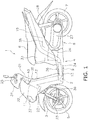
- FIG. 1 is a side view of the straddled vehicle 1.
- the straddled vehicle 1 according to the present preferred embodiment is a scooter-type vehicle.
- the straddled vehicle 1 includes a vehicle body frame 2, a steering device 3, a vehicle body cover 4, a front wheel 5, a seat 6, a rear wheel 7, a power unit 8 and a fuel tank 9.
- a back-and-forth direction, an up-and-down direction and a right-and-left direction of the straddled vehicle 1 refer to the back-and-forth direction, the up-and-down direction and the right-and-left direction seen from a rider riding on the straddled vehicle 1.
- the back-and-forth direction is defined as not only indicating directions arranged in parallel to the back-and-forth direction of the straddled vehicle 1, but also encompassing directions tilting within an angular range of ⁇ 45 degrees with respect to the back-and-forth direction of the straddled vehicle 1.
- a given direction closer to the back-and-forth direction than to the right-and-left direction and the up-and-down direction is classified as the back-and-forth direction.
- the up-and-down direction is defined as encompassing directions tilting within an angular range of ⁇ 45 degrees with respect to the up-and-down direction of the straddled vehicle 1.
- a given direction closer to the up-and-down direction than to the back-and-forth direction and the right-and-left direction is classified as the up-and-down direction.
- the right-and-left direction is defined as encompassing directions tilting within an angular range of ⁇ 45 degrees with respect to the right-and-left direction of the straddled vehicle 1.
- a given direction closer to the right-and-left direction than to the back-and-forth direction and the up-and-down direction is classified as the right-and-left direction.
- connection is not limited to direct connection, and encompasses indirect connection. Additionally, the term “connection” is not limited to a condition that separate members are fixed to each other, and encompasses a condition that a plurality of portions in an integrated member continue to each other.
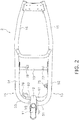
- FIG. 2 is a plan view of the vehicle body frame 2.
- the vehicle body frame 2 includes a head pipe 11, a down frame 12, a first lower frame 13, a second lower frame 14, a first rear frame 15 and a second rear frame 16.
- the head pipe 11 tilts backward and upward.
- the down frame 12 extends downward from the head pipe 11.
- the first lower frame 13 and the second lower frame 14 are connected to a lower part of the down frame 12.
- the first lower frame 13 extends leftward and backward from the down frame 12.
- the second lower frame 14 extends rightward and backward from the down frame 12.
- the first rear frame 15 extends backward and upward from the first lower frame 13.
- the second rear frame 16 extends backward and upward from the second lower frame 14.
- the steering device 3 is turnably supported by the head pipe 11.
- the steering device 3 includes a steering shaft 21, an under bracket 22 and right and left suspensions 23. It should be noted that FIG. 1 shows only the left suspension 23.
- the steering shaft 21 is inserted into the head pipe 11.
- the steering shaft 21 is connected at an upper part thereof to a handle 25.
- the steering shaft 21 is supported by the head pipe 11 and is thereby turnable right and left.
- the under bracket 22 is connected to a lower part of the steering shaft 21.
- the right and left suspensions 23 are connected at the upper ends thereof to the under bracket 22.
- the front wheel 5 is rotatably supported by the right and left suspensions 23.
- the vehicle body cover 4 includes a handle cover 31, a front cover 32, a rear cover 33, a lower cover 34, a leg shield 35 and a mud cover 39.
- the handle cover 31 covers the front and rear sides of the handle 25.
- the front cover 32 is disposed in front of the head pipe 11 and the down frame 12.
- a headlight 37 is disposed in the front cover 32.
- the leg shield 35 is disposed behind the front cover 32.
- the leg shield 35 is disposed behind the head pipe 11 and the down frame 12.
- the mud cover 39 is disposed behind the front wheel 5 and in front of the leg shield 35.
- the rear cover 33 covers the surroundings of the first and second rear frames 15 and 16. The rear cover 33 is disposed below the seat 6.
- the seat 6 is disposed backward of the head pipe 11.
- the seat 6 is disposed directly above the first and second rear frames 15 and 16.
- a storage box 38 is disposed inside the rear cover 33.
- the storage box 38 is disposed directly below the seat 6.
- the lower cover 34 is disposed between the front cover 32 and the rear cover 33.
- the lower cover 34 covers the surroundings of the first and second lower frames 13 and 14.
- the upper surface of the lower cover 34 includes a footboard 36.
- the footboard 36 is disposed below and forward of the seat 6.
- the footboard 36 is disposed directly above the first and second lower frames 13 and 14. In other words, as seen in the vehicle plan view, the footboard 36 overlaps the first and second lower frames 13 and 14.
- the footboard 36 is disposed between the leg shield 35 and the rear cover 33 in the vehicle back-and-forth direction.
- the fuel tank 9 is disposed directly below the footboard 36. In other words, as seen in the vehicle plan view, the fuel tank 9 overlaps the footboard 36.
- the footboard 36 is provided for allowing a rider to put his/her feet thereon.
- the footboard 36 has an entirely flat shape in a vehicle width direction.
- the footboard 36 may not have a flat shape.
- a center tunnel portion may be provided in the middle of the footboard 36.
- the center tunnel portion has an upwardly protruding shape and extends in the back-and-forth direction.
- the power unit 8 is disposed directly below the seat 6.
- the power unit 8 is pivotably supported by the vehicle body frame 2.
- the power unit 8 supports the rear wheel 7 such that the rear wheel 7 is rotatable.
- the rear wheel 7 is supported by the vehicle body frame 2 through a rear suspension 28.
- the power unit 8 includes an engine 26 and a transmission 27.
- FIG. 3 is a perspective view of the vehicle body frame 2 and the fuel tank 9.
- FIG. 4 is a side view of the vehicle body frame 2 and the fuel tank 9.
- FIG. 5 is a front view of the vehicle body frame 2 and the fuel tank 9.
- FIG. 6 is an enlarged plan view of the vehicle body frame 2 and the fuel tank 9.
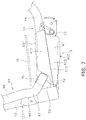
- FIG. 7 is an enlarged side view of the vehicle body frame 2 and the fuel tank 9. It should be noted that the first lower frame 13 is not shown in FIG. 7 .
- FIG. 8 is an enlarged side view of the vehicle body frame 2.
- the fuel tank 9 is disposed between the first lower frame 13 and the second lower frame 14 in the vehicle right-and-left direction.
- the fuel tank 9 includes a tank body 41 and an inlet pipe 42.
- the tank body 41 has a space for storing fuel in the interior thereof.
- the tank body 41 includes an upper body 411 and a lower body 412.
- the upper body 411 and the lower body 412 are provided separately from each other.
- the tank body 41 is structured to be split into up and down parts.
- the fuel tank 9 includes a flange portion 413.
- the flange portion 413 protrudes from the tank body 41 forward, rearward, rightward and leftward.
- the upper body 411 and the lower body 412 are joined at the flange portion 413.
- the inlet pipe 42 is connected to the tank body 41.
- the inlet pipe 42 is connected to the upper body 411.
- the inlet pipe 42 protrudes forward and upward from the tank body 41.
- the inlet pipe 42 is located backward of the down
- the straddled vehicle 1 includes a filler port 43 and a fuel pipe 44.
- the filler port 43 is disposed laterally to the head pipe 11. In the vehicle side view, the filler port 43 overlaps the head pipe 11.
- the filler port 43 is disposed on and through the leg shield 35.
- the fuel pipe 44 connects the filler port 43 and the fuel tank 9 therethrough. As seen in the vehicle side view, the fuel pipe 44 is at least in part disposed behind the front wheel 5.
- the fuel pipe 44 is at least in part disposed between the mud cover 39 and the leg shield 35, both of which are shown in FIG. 1 .
- the fuel pipe 44 extends forward and upward from the fuel tank 9, and then extends upward along the down frame 12.
- a front edge 441 of the fuel pipe 44 is located backward of a front edge 121 of the down frame 12.
- the fuel pipe 44 includes a first pipe portion 45, a second pipe portion 46 and a bent pipe portion 47.
- the first pipe portion 45 is connected to the fuel tank 9.
- the first pipe portion 45 is connected to the inlet pipe 42.
- the first pipe portion 45 extends forward and upward.
- the second pipe portion 46 is disposed laterally to the down frame 12. As seen in the vehicle side view, the second pipe portion 46 at least in part overlaps the down frame 12. The second pipe portion 46 extends upward along the down frame 12. As seen in the vehicle side view, the second pipe portion 46 is located backward of the front edge 121 of the down frame 12. The second pipe portion 46 is connected to the filler port 43.
- the bent pipe portion 47 is located between the first pipe portion 45 and the second pipe portion 46.
- the bent pipe portion 47 is located in front of the footboard 36.
- the bent pipe portion 47 is at least in part located at the same height as the footboard 36. In other words, the bent pipe portion 47 overlaps the footboard 36 as seen in the vehicle front view. As seen in the vehicle side view, the bent pipe portion 47 at least in part overlaps the down frame 12. As seen in the vehicle side view, the bent pipe portion 47 is located backward of the front edge 121 of the down frame 12.
- FIG. 9 is a cross-sectional view of FIG. 8 taken along line IX-IX.
- the first lower frame 13 includes a first frame front portion 51 and a first frame rear portion 52.
- the second lower frame 14 includes a second frame front portion 53 and a second frame rear portion 54.
- the first lower frame 13 and the second lower frame 14 are shaped to be bilaterally asymmetrical from each other.
- the first frame front portion 51 and the second frame front portion 53 are shaped to be bilaterally asymmetrical to each other.
- the first frame front portion 51 is located in front of the fuel tank 9.
- the first frame front portion 51 is connected to the down frame 12.
- the first frame front portion 51 extends forward and sideward from the down frame 12 and then curves backward. As seen in the vehicle plan view, the first frame front portion 51 curves to protrude forward.
- the first frame rear portion 52 extends backward from the first frame front portion 51.
- the first frame rear portion 52 is connected to the first rear frame 15.
- the second frame front portion 53 is connected to the down frame 12.
- the second frame front portion 53 extends sideward from the down frame 12 and then curves backward.
- the second frame rear portion 54 extends backward from the second frame front portion 53.
- the second frame rear portion 54 is connected to the second rear frame 16.
- the first frame front portion 51 curves to further protrude forward than the second frame front portion 53.
- a front edge 511 of the first frame front portion 51 is at least in part located forward of a front edge 531 of the second frame front portion 53.
- a rear edge 512 of the first frame front portion 51 is at least in part located forward of a rear edge 532 of the second frame front portion 53.
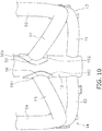
- FIG. 10 is an enlarged front view of the vehicle body frame 2.
- the first lower frame 13 includes a first connecting end portion 55 connected to the down frame 12.
- the second lower frame 14 includes a second connecting end portion 56 connected to the down frame 12.
- the first connecting end portion 55 is at least in part located above the second connecting end portion 56.
- an upper end 551 of the first connecting end portion 55 is located above an upper end 561 of the second connecting end portion 56.
- a lower end 552 of the first connecting end portion 55 is located above a lower end 562 of the second connecting end portion 56.
- the first frame front portion 51 extends downward and sideward from the first connecting end portion 55.
- the second frame front portion 53 extends downward and sideward from the second connecting end portion 56.
- the first frame rear portion 52 and the second frame rear portion 54 are located at approximately the same height as each other. As seen in the vehicle side view of FIG. 4 , the first frame rear portion 52 overlaps the fuel tank 9. As seen in the vehicle side view, a top surface 901 of the fuel tank 9 is at least in part located above an upper edge 521 of the first frame rear portion 52. As seen in the vehicle side view, a bottom surface 902 of the fuel tank 9 is at least in part located below a lower edge 522 of the first frame rear portion 52. As seen in the vehicle side view, the inlet pipe 42 at least in part overlaps the first lower frame 13.
- a center axis C1 of the first lower frame 13 is located forward of a center axis C2 of the down frame 12 at the first connecting end portion 55.
- the front edge 511 of the first frame front portion 51 is at least in part located forward of the front edge 121 of the down frame 12.
- the rear edge 512 of the first frame front portion 51 is at least in part located forward of the center axis C2 of the down frame 12.
- the rear edge 512 of the first frame front portion 51 is at least in part located forward of a rear end 553 of the first connecting end portion 55.
- the reference sign "12a" denotes a portion of the down frame 12, which is depicted with a cross section taken along a horizontal plane passing through the first connecting end portion 55.
- the first frame front portion 51 curves to further protrude forward than the portion 12a of the down frame 12.
- the front edge 511 of the first frame front portion 51 is at least in part located forward of the front end of the portion 12a of the down frame 12.
- the rear edge 512 of the first frame front portion 51 is at least in part located forward of the rear end of the portion 12a of the down frame 12.
- the vehicle body frame 2 includes a first reinforcement member 61 and a second reinforcement member 62.
- the first reinforcement member 61 extends from the down frame 12 to one lateral side and then curves backward.
- the second reinforcement member 62 extends from the down frame 12 to the other lateral side and then curves backward.
- the first reinforcement member 61 is disposed directly below the first lower frame 13.
- the first reinforcement member 61 is connected to the down frame 12 and the first lower frame 13.
- the first reinforcement member 61 is connected to the down frame 12 at a lower position than the first connecting end portion 55.
- the second reinforcement member 62 is disposed directly below the second lower frame 14.
- the second reinforcement member 62 is connected to the down frame 12 and the second lower frame 14.
- the second reinforcement member 62 is connected to the down frame 12 at a lower position than the second connecting end portion 56.
- the front edge 511 of the first frame front portion 51 is at least in part located forward of a front edge 611 of the first reinforcement member 61.
- the rear edge 512 of the first frame front portion 51 is at least in part located forward of the front edge 611 of the first reinforcement member 61.
- the front edge 531 of the second frame front portion 53 is at least in part located forward of a front edge 621 of the second reinforcement member 62.
- the rear edge 532 of the second frame front portion 53 is at least in part located backward of the front edge 621 of the second reinforcement member 62.
- the rear edge 532 of the second frame front portion 53 is at least in part located forward of a rear edge 622 of the second reinforcement member 62.
- the fuel tank 9 includes a plurality of attachment portions 71 to 74 for attaching the fuel tank 9 to the vehicle body frame 2.
- the attachment portions 71 to 74 are provided in the flange portion 413.
- Each of the attachment portions 71 to 74 includes a hole, and is attached to the vehicle body frame 2 by inserting a fixation member such as a bolt into the hole.
- the fuel tank 9 includes the first attachment portion 71, the second attachment portion 72, the third attachment portion 73 and the fourth attachment portion 74.
- the first attachment portion 71 is disposed laterally to the tank body 41. As seen in the vehicle plan view, the first attachment portion 71 is disposed away from the down frame 12 to the left side. The first attachment portion 71 is disposed on the left side of the tank body 41. As seen in the vehicle plan view, the first attachment portion 71 is disposed behind the first frame front portion 51. As seen in FIG. 9 , a first bracket 75 is attached to the first lower frame 13. The first attachment portion 71 is attached to the first lower frame 13 through the first bracket 75.
- the second attachment portion 72 is disposed away from the down frame 12 to the right side.
- the second attachment portion 72 is disposed in front of the tank body 41.
- a second bracket 76 is attached to the second lower frame 14.
- the second attachment portion 72 is attached to the second lower frame 14 through the second bracket 76.
- the third and fourth attachment portions 73 and 74 are disposed behind the tank body 41.
- the vehicle body frame 2 includes a cross member 19.
- the cross member 19 extends in the vehicle width direction and is connected to the first and second lower frames 13 and 14.
- a third bracket 77 and a fourth bracket 78 are attached to the cross member 19.
- the third attachment portion 73 is attached to the cross member 19 through the third bracket 77.
- the fourth attachment portion 74 is attached to the cross member 19 through the fourth bracket 78.
- the fuel pipe 44 is disposed to pass behind the first frame front portion 51.
- the fuel pipe 44 is located backward of the first frame front portion 51 in a position located just behind the first frame front portion 51.
- the fuel pipe 44 is located backward of the first frame front portion 51 in a position located below the first connecting end portion 55.
- the fuel pipe 44 at least in part overlaps the down frame 12 in a position located just behind the first frame front portion 51.
- the front edge 441 of the fuel pipe 44 at least in part overlaps the down frame 12 in a position located just behind the first frame front portion 51.
- the fuel pipe 44 at least in part overlaps the down frame 12 in a position located below the first connecting end portion 55.
- the front edge 441 of the fuel pipe 44 at least in part overlaps the down frame 12 in a position located below the first connecting end portion 55.
- the fuel pipe 44 is disposed to pass behind the first frame front portion 51. Because of this, a large space can be reliably produced between the front wheel 5 and the fuel pipe 44, while increase in size of the straddled vehicle 1 can be inhibited. Additionally, the first frame front portion 51 curves to protrude forward as seen in the vehicle plan view. Because of this, the fuel pipe 44 can be disposed in as forward a position as possible. Accordingly, the footboard 36 can be enlarged in the back-and-forth direction. In other words, a space for putting the feet of a rider can be expanded.
- the front edge 511 of the first frame front portion 51 is at least in part located forward of the front edge 121 of the down frame 12 as seen in the vehicle side view. Because of this, the fuel pipe 44 can be disposed in as forward a position as possible. Accordingly, the footboard 36 can be enlarged in the back-and-forth direction.
- the rear edge 512 of the first frame front portion 51 is at least in part located forward of the center axis C2 of the down frame 12 as seen in the vehicle side view. Because of this, the first frame front portion 51 largely curves to protrude forward, whereby the fuel pipe 44 can be disposed in as forward a position as possible. Accordingly, the footboard 36 can be enlarged in the back-and-forth direction.
- the first connecting end portion 55 is at least in part located above the second connecting end portion 56 as seen in the vehicle front view.
- the first connecting end portion 55 is disposed in a high position, whereby the stiffness of the first lower frame 13 can be enhanced. Accordingly, even when the first frame front portion 51 curves forward, degradation in stiffness of the first lower frame 13 can be inhibited.
- the center axis C1 of the first lower frame 13 is located forward of the center axis C2 of the down frame 12 at the first connecting end portion 55 as seen in the vehicle side view. Because of this, the first frame front portion 51 largely curves to protrude forward, whereby the fuel pipe 44 can be disposed in as forward a position as possible. Accordingly, the footboard 36 can be enlarged in the back-and-forth direction.
- the rear edge 512 of the first frame front portion 51 is at least in part located forward of the rear end 553 of the first connecting end portion 55 as seen in the vehicle plan view. Because of this, the first frame front portion 51 largely curves to protrude forward, whereby the fuel pipe 44 can be disposed in as forward a position as possible. Accordingly, the footboard 36 can be enlarged in the back-and-forth direction.
- the fuel pipe 44 at least in part overlaps the down frame 12 in a position located just behind the first frame front portion 51 as seen in the vehicle side view. Because of this, the fuel pipe 44 is disposed in as forward a position as possible, whereby the footboard 36 can be enlarged in the back-and-forth direction.
- the bent pipe portion 47 of the fuel pipe 44 is located in front of the footboard 36, and overlaps the footboard 36 as seen in the vehicle front view. Because of this, the bent pipe portion 47 can be disposed in adjacent to the footboard 36, while avoiding from interfering the footboard 36. Accordingly, the footboard 36 can be enlarged in the back-and-forth direction.
- the bent pipe portion 47 overlaps the down frame 12 as seen in the vehicle side view. Because of this, the fuel pipe 44 is herein disposed in as forward a position as possible, whereby the footboard 36 can be enlarged in the back-and-forth direction.
- the front edge 441 of the fuel pipe 44 is located backward of the front edge 121 of the down frame 12 as seen in the vehicle side view. Because of this, a large space can be reliably produced between the front wheel 5 and the fuel pipe 44, while increase in size of the vehicle can be inhibited.
- the straddled vehicle 1 is not limited to a scooter-type vehicle, and alternatively, may be another type of vehicle.
- the number of front wheels is not limited to one, and alternatively, may be two or greater.
- the number of rear wheels is not limited to one, and alternatively, may be two or greater.
- the structure of the vehicle body frame 2 is not limited to that of the aforementioned preferred embodiment, and may be changed.
- the head pipe 11, the down frame 12, the first lower frame 13, the second lower frame 14, the first rear frame 15 or the second rear frame 16 may be changed in shape or layout.
- the first frame front portion 51, the first frame rear portion 52, the second frame front portion 53 or the second frame rear portion 54 may be changed in shape or layout.
- first lower frame 13 and the second lower frame 14 may be bilaterally reversed to those in the aforementioned preferred embodiment.
- both the fuel pipe 44 and the filler port 43 may be disposed bilaterally on the opposite side of those in the aforementioned preferred embodiment.
- the first connecting end portion 55 or the second connecting end portion 56 may be changed in shape or layout.
- the fuel tank 9, the fuel pipe 44 or the filler port 43 may be changed in shape or layout.
- the first reinforcement member 61 or the second reinforcement member 62 may be changed in shape or layout. Instead of this, the first reinforcement member 61 and/or the second reinforcement member 62 may be omitted.
Landscapes
- Engineering & Computer Science (AREA)
- Mechanical Engineering (AREA)
- Automatic Cycles, And Cycles In General (AREA)
- Cooling, Air Intake And Gas Exhaust, And Fuel Tank Arrangements In Propulsion Units (AREA)
- Body Structure For Vehicles (AREA)
- Automobile Manufacture Line, Endless Track Vehicle, Trailer (AREA)
Abstract
Description
- The present invention relates to a straddled vehicle.
- There has been conventionally a type of straddled vehicle in which a fuel tank is disposed directly below a footboard while a fuel port is disposed on a leg shield (see e.g.,
JP 2010-215214 A - In the aforementioned straddled vehicle, the fuel pipe is disposed directly below and in front of the lower frame. Therefore, when it is intended to reliably produce a required distance between a front wheel and the fuel pipe, chances are that the vehicle is unwillingly increased in size. On the other hand, when the fuel pipe is disposed behind the lower frame, the required distance can be easily and reliably produced between the front wheel and the fuel pipe. In this case, however, the position of the leg shield is configured to be shifted to a further rear side than that when the fuel pipe is disposed directly below and in front of the lower frame. Hence, this poses a drawback of reduction in space for putting the feet of a rider.
- It is an object of the present invention to provide a straddled vehicle, wherein a large space between a front wheel and a fuel pipe is reliably produced while increase in size of the straddled vehicle is inhibited, and besides, to expand a space for putting the feet of a rider in the straddled vehicle. According to the present invention said object is solved by a straddled vehicle having the features of independent claim 1. Preferred embodiments are laid down in the dependent claims.
- A straddled vehicle according to an aspect includes a head pipe, a steering device, a front wheel, a down frame, a first lower frame, a second lower frame, a first rear frame, a second rear frame, a seat, a front cover, a leg shield, a rear cover, a footboard, a fuel tank, a filler port and a fuel pipe. The steering device is turnably supported by the head pipe. The front wheel is rotatably supported by the steering device. The down frame extends downward from the head pipe. The first lower frame extends backward and to one of right and left sides from the down frame. The second lower frame extends backward and to the other of the right and left sides from the down frame. The first rear frame extends backward and upward from the first lower frame. The second rear frame extends backward and upward from the second lower frame. The seat is disposed directly above the first rear frame and the second rear frame.
- The front cover is disposed in front of the head pipe and the down frame. The leg shield is disposed behind the front cover. The rear cover is disposed directly below the seat. The footboard is disposed directly above the first lower frame and the second lower frame, and is disposed between the leg shield and the rear cover in a vehicle back-and-forth direction. The fuel tank is disposed directly below the footboard, and is disposed between the first lower frame and the second lower frame in a vehicle right-and-left direction. The filler port is disposed on the leg shield. The fuel pipe connects the filler port and the fuel tank. The fuel pipe is at least in part disposed behind the front wheel as seen in a vehicle side view.
- The first lower frame includes a first frame front portion. The first frame front portion is connected to the down frame, and is located in front of the fuel tank. The first frame front portion curves to further protrude forward than the down frame as seen in a vehicle plan view. The fuel pipe is disposed to pass behind the first frame front portion.
- In the straddled vehicle according to the present aspect, the fuel pipe is disposed to pass behind the first frame front portion. Because of this, a large space can be reliably produced between the front wheel and the fuel pipe, while increase in size of the vehicle can be inhibited. Additionally, the first frame front portion curves to further protrude forward than the down frame as seen in the vehicle plan view. Because of this, the fuel pipe can be disposed in as forward a position as possible. Accordingly, the footboard can be enlarged in the back-and-forth direction. In other words, a space for putting the feet of a rider can be expanded.
- A front edge of the first frame front portion may be at least in part located forward of a front edge of the down frame as seen in the vehicle side view. In this case, the fuel pipe can be disposed in as forward a position as possible. Accordingly, the footboard can be enlarged in the back-and-forth direction.
- A rear edge of the first frame front portion may be at least in part located forward of a center axis of the down frame as seen in the vehicle side view. In this case, the first frame front portion largely curves to protrude forward, whereby the fuel pipe can be disposed in as forward a position as possible. Accordingly, the footboard can be enlarged in the back-and-forth direction.
- The second lower frame may include a second frame front portion connected to the down frame. The first frame front portion may curve to further protrude forward than the second frame front portion. As described above, the first frame front portion curves to protrude forward, whereby the fuel pipe can be disposed in as forward a position as possible. Accordingly, the space for putting the feet of a rider can be expanded. However, from the perspective of reducing stress concentration on a part at which the down frame and the first lower frame are connected, the down frame is preferably disposed to overlap the first lower frame as seen in the side view. By contrast, when the first frame front portion curves to protrude forward, stress concentration inevitably shifts forward. Accordingly, degradation in stiffness of the first lower frame is concerned. Especially, when the first and second lower frames are shaped symmetrically to each other, degradation in stiffness of the both is concerned. Moreover in attempt to enhance the stiffness of the first and second lower frames per se so as to inhibit degradation in stiffness of the both, increase in size of the first and second lower frames is concerned. Furthermore, with increase in size of the first and second lower frames, the position of the leg shield is shifted backward. Accordingly, reduction in space for putting the feet of a rider is also concerned. In view of the above, according to the present aspect, the first frame front portion curves to further protrude forward than the second frame front portion. In other words, the first and second lower frames are shaped asymmetrically from each other. Because of this, degradation in stiffness of the first lower frame can be compensated by the second lower frame. Therefore, degradation in stiffness of the first and second lower frames can be inhibited, while increase in size of the first and second lower frames can be inhibited.
- The first lower frame may include a first connecting end portion connected to the down frame. The second lower frame may include a second connecting end portion connected to the down frame. The first connecting end portion may be at least in part located above the second connecting end portion as seen in a vehicle front view. As described above, when the first frame front portion curves forward, degradation in stiffness of the first lower frame is concerned. Additionally, in attempt to enhance the stiffness of the first lower frame per se, increase in size of the first lower frame and reduction in space for putting the feet of a rider are concerned. However, according to the present aspect, the first connecting end portion is disposed in a high position, whereby the stiffness of the first lower frame can be enhanced. Because of this, even when the first frame front portion curves forward, degradation in stiffness of the first lower frame can be inhibited while increase in size of the first lower frame and reduction in space for putting the feet of a rider can be inhibited.
- An upper end of the first connecting end portion may be located above an upper end of the second connecting end portion as seen in the vehicle front view. In this case, the first connecting end portion is disposed in a high position, whereby the stiffness of the first lower frame can be enhanced. Accordingly, even when the first frame front portion curves, degradation in stiffness of the first lower frame can be inhibited.
- A lower end of the first connecting end portion may be located above a lower end of the second connecting end portion as seen in the vehicle front view. In this case, the first connecting end portion is disposed in a high position, whereby the stiffness of the first lower frame can be enhanced. Accordingly, even when the first frame front portion curves, degradation in stiffness of the first lower frame can be inhibited.
- A center axis of the first lower frame may be located forward of the center axis of the down frame at the first connecting end portion as seen in the vehicle side view. In this case, the first frame front portion largely curves to protrude forward, whereby the fuel pipe can be disposed in as forward a position as possible. Accordingly, the footboard can be enlarged in the back-and-forth direction.
- The rear edge of the first frame front portion may be at least in part located forward of a rear end of the first connecting end portion as seen in the vehicle plan view. In this case, the first frame front portion largely curves to protrude forward, whereby the fuel pipe can be disposed in as forward a position as possible. Accordingly, the footboard can be enlarged in the back-and-forth direction.
- The fuel pipe may at least in part overlap the down frame in a position located just behind the first frame front portion as seen in the vehicle side view. In this case, the fuel pipe is disposed in as forward a position as possible, whereby the footboard can be enlarged in the back-and-forth direction.
- The fuel pipe may include a first pipe portion, a second pipe portion and a bent pipe portion. The first pipe portion may be connected to the fuel tank. The second pipe portion may be disposed laterally to the down frame. The bent pipe portion may be located between the first pipe portion and the second pipe portion. The bent pipe portion may be located in front of the footboard, and may overlap the footboard as seen in the vehicle front view. In this case, the bent pipe portion can be disposed in adjacent to the footboard, while avoiding from interfering with the footboard. Accordingly, the footboard can be enlarged in the back-and-forth direction.
- The bent pipe portion may at least in part overlap the down frame as seen in the vehicle side view. In this case, the fuel pipe is disposed in as forward a position as possible, whereby the footboard can be enlarged in the back-and-forth direction.
- A front edge of the fuel pipe may be located backward of the front edge of the down frame as seen in the vehicle side view. In this case, a large space can be reliably produced between the front wheel and the fuel pipe, while increase in size of the vehicle can be inhibited.
- Overall, according to the present teaching, it is possible to reliably produce a large space between the front wheel and the fuel pipe in the straddled vehicle while increase in size of the straddled vehicle is inhibited, and besides, to expand a space for putting the feet of a rider in the straddled vehicle.
-
-
FIG. 1 is a side view of a straddled vehicle according to a preferred embodiment. -
FIG. 2 is a plan view of a vehicle body frame. -
FIG. 3 is a perspective view of the vehicle body frame and a fuel tank. -
FIG. 4 is a side view of the vehicle body frame and the fuel tank. -
FIG. 5 is a front view of the vehicle body frame and the fuel tank. -
FIG. 6 is an enlarged plan view of the vehicle body frame and the fuel tank. -
FIG. 7 is an enlarged side view of the vehicle body frame and the fuel tank. -
FIG. 8 is an enlarged side view of the vehicle body frame. -
FIG. 9 is a cross-sectional view ofFIG. 8 taken along line IX-IX. -
FIG. 10 is an enlarged front view of the vehicle body frame. - A straddled vehicle 1 according to a preferred embodiment will be hereinafter explained with reference to drawings.
FIG. 1 is a side view of the straddled vehicle 1. The straddled vehicle 1 according to the present preferred embodiment is a scooter-type vehicle. As shown inFIG. 1 , the straddled vehicle 1 includes avehicle body frame 2, asteering device 3, avehicle body cover 4, a front wheel 5, aseat 6, a rear wheel 7, a power unit 8 and afuel tank 9. - It should be noted that in the present specification, a back-and-forth direction, an up-and-down direction and a right-and-left direction of the straddled vehicle 1 refer to the back-and-forth direction, the up-and-down direction and the right-and-left direction seen from a rider riding on the straddled vehicle 1. Additionally, the back-and-forth direction is defined as not only indicating directions arranged in parallel to the back-and-forth direction of the straddled vehicle 1, but also encompassing directions tilting within an angular range of ±45 degrees with respect to the back-and-forth direction of the straddled vehicle 1. In other words, a given direction closer to the back-and-forth direction than to the right-and-left direction and the up-and-down direction is classified as the back-and-forth direction.
- Likewise, the up-and-down direction is defined as encompassing directions tilting within an angular range of ±45 degrees with respect to the up-and-down direction of the straddled vehicle 1. In other words, a given direction closer to the up-and-down direction than to the back-and-forth direction and the right-and-left direction is classified as the up-and-down direction. Moreover, the right-and-left direction is defined as encompassing directions tilting within an angular range of ±45 degrees with respect to the right-and-left direction of the straddled vehicle 1. In other words, a given direction closer to the right-and-left direction than to the back-and-forth direction and the up-and-down direction is classified as the right-and-left direction.
- In the present specification, the term "connection" is not limited to direct connection, and encompasses indirect connection. Additionally, the term "connection" is not limited to a condition that separate members are fixed to each other, and encompasses a condition that a plurality of portions in an integrated member continue to each other.
-
FIG. 2 is a plan view of thevehicle body frame 2. As shown inFIGS. 1 and2 , thevehicle body frame 2 includes ahead pipe 11, adown frame 12, a firstlower frame 13, a secondlower frame 14, a firstrear frame 15 and a secondrear frame 16. As seen in the vehicle side view, thehead pipe 11 tilts backward and upward. The downframe 12 extends downward from thehead pipe 11. - The first
lower frame 13 and the secondlower frame 14 are connected to a lower part of thedown frame 12. The firstlower frame 13 extends leftward and backward from thedown frame 12. The secondlower frame 14 extends rightward and backward from thedown frame 12. The firstrear frame 15 extends backward and upward from the firstlower frame 13. The secondrear frame 16 extends backward and upward from the secondlower frame 14. - The
steering device 3 is turnably supported by thehead pipe 11. Thesteering device 3 includes a steeringshaft 21, an underbracket 22 and right and leftsuspensions 23. It should be noted thatFIG. 1 shows only theleft suspension 23. The steeringshaft 21 is inserted into thehead pipe 11. The steeringshaft 21 is connected at an upper part thereof to ahandle 25. The steeringshaft 21 is supported by thehead pipe 11 and is thereby turnable right and left. The underbracket 22 is connected to a lower part of the steeringshaft 21. The right and leftsuspensions 23 are connected at the upper ends thereof to the underbracket 22. The front wheel 5 is rotatably supported by the right and leftsuspensions 23. - The
vehicle body cover 4 includes ahandle cover 31, afront cover 32, arear cover 33, alower cover 34, aleg shield 35 and amud cover 39. Thehandle cover 31 covers the front and rear sides of thehandle 25. A meter panel, including a speedometer and so forth, is attached to the upper surface of thehandle cover 31. - The
front cover 32 is disposed in front of thehead pipe 11 and thedown frame 12. Aheadlight 37 is disposed in thefront cover 32. Theleg shield 35 is disposed behind thefront cover 32. Theleg shield 35 is disposed behind thehead pipe 11 and thedown frame 12. Themud cover 39 is disposed behind the front wheel 5 and in front of theleg shield 35. Therear cover 33 covers the surroundings of the first and second rear frames 15 and 16. Therear cover 33 is disposed below theseat 6. - The
seat 6 is disposed backward of thehead pipe 11. Theseat 6 is disposed directly above the first and second rear frames 15 and 16. Astorage box 38 is disposed inside therear cover 33. Thestorage box 38 is disposed directly below theseat 6. Thelower cover 34 is disposed between thefront cover 32 and therear cover 33. Thelower cover 34 covers the surroundings of the first and secondlower frames lower cover 34 includes afootboard 36. - The
footboard 36 is disposed below and forward of theseat 6. Thefootboard 36 is disposed directly above the first and secondlower frames footboard 36 overlaps the first and secondlower frames footboard 36 is disposed between theleg shield 35 and therear cover 33 in the vehicle back-and-forth direction. Thefuel tank 9 is disposed directly below thefootboard 36. In other words, as seen in the vehicle plan view, thefuel tank 9 overlaps thefootboard 36. - The
footboard 36 is provided for allowing a rider to put his/her feet thereon. Thefootboard 36 has an entirely flat shape in a vehicle width direction. However, thefootboard 36 may not have a flat shape. For example, a center tunnel portion may be provided in the middle of thefootboard 36. The center tunnel portion has an upwardly protruding shape and extends in the back-and-forth direction. - The power unit 8 is disposed directly below the
seat 6. The power unit 8 is pivotably supported by thevehicle body frame 2. The power unit 8 supports the rear wheel 7 such that the rear wheel 7 is rotatable. The rear wheel 7 is supported by thevehicle body frame 2 through arear suspension 28. The power unit 8 includes anengine 26 and atransmission 27. - Next, configurations of the
vehicle body frame 2 and thefuel tank 9 will be explained.FIG. 3 is a perspective view of thevehicle body frame 2 and thefuel tank 9.FIG. 4 is a side view of thevehicle body frame 2 and thefuel tank 9.FIG. 5 is a front view of thevehicle body frame 2 and thefuel tank 9.FIG. 6 is an enlarged plan view of thevehicle body frame 2 and thefuel tank 9.FIG. 7 is an enlarged side view of thevehicle body frame 2 and thefuel tank 9. It should be noted that the firstlower frame 13 is not shown inFIG. 7 .FIG. 8 is an enlarged side view of thevehicle body frame 2. - The
fuel tank 9 is disposed between the firstlower frame 13 and the secondlower frame 14 in the vehicle right-and-left direction. As shown inFIGS. 6 and7 , thefuel tank 9 includes atank body 41 and aninlet pipe 42. Thetank body 41 has a space for storing fuel in the interior thereof. Thetank body 41 includes anupper body 411 and alower body 412. Theupper body 411 and thelower body 412 are provided separately from each other. Hence, thetank body 41 is structured to be split into up and down parts. Thefuel tank 9 includes aflange portion 413. Theflange portion 413 protrudes from thetank body 41 forward, rearward, rightward and leftward. Theupper body 411 and thelower body 412 are joined at theflange portion 413. Theinlet pipe 42 is connected to thetank body 41. Detailedly, theinlet pipe 42 is connected to theupper body 411. Theinlet pipe 42 protrudes forward and upward from thetank body 41. Theinlet pipe 42 is located backward of thedown frame 12. - As shown in
FIGS. 3 to 7 , the straddled vehicle 1 includes afiller port 43 and afuel pipe 44. As shown inFIG. 4 , thefiller port 43 is disposed laterally to thehead pipe 11. In the vehicle side view, thefiller port 43 overlaps thehead pipe 11. As shown inFIG. 1 , thefiller port 43 is disposed on and through theleg shield 35. Thefuel pipe 44 connects thefiller port 43 and thefuel tank 9 therethrough. As seen in the vehicle side view, thefuel pipe 44 is at least in part disposed behind the front wheel 5. Thefuel pipe 44 is at least in part disposed between themud cover 39 and theleg shield 35, both of which are shown inFIG. 1 . Thefuel pipe 44 extends forward and upward from thefuel tank 9, and then extends upward along thedown frame 12. - As seen in the vehicle side view of
FIG. 7 , afront edge 441 of thefuel pipe 44 is located backward of afront edge 121 of thedown frame 12. Thefuel pipe 44 includes afirst pipe portion 45, asecond pipe portion 46 and abent pipe portion 47. Thefirst pipe portion 45 is connected to thefuel tank 9. Detailedly, thefirst pipe portion 45 is connected to theinlet pipe 42. Thefirst pipe portion 45 extends forward and upward. - The
second pipe portion 46 is disposed laterally to thedown frame 12. As seen in the vehicle side view, thesecond pipe portion 46 at least in part overlaps thedown frame 12. Thesecond pipe portion 46 extends upward along thedown frame 12. As seen in the vehicle side view, thesecond pipe portion 46 is located backward of thefront edge 121 of thedown frame 12. Thesecond pipe portion 46 is connected to thefiller port 43. - The
bent pipe portion 47 is located between thefirst pipe portion 45 and thesecond pipe portion 46. Thebent pipe portion 47 is located in front of thefootboard 36. Thebent pipe portion 47 is at least in part located at the same height as thefootboard 36. In other words, thebent pipe portion 47 overlaps thefootboard 36 as seen in the vehicle front view. As seen in the vehicle side view, thebent pipe portion 47 at least in part overlaps thedown frame 12. As seen in the vehicle side view, thebent pipe portion 47 is located backward of thefront edge 121 of thedown frame 12. -
FIG. 9 is a cross-sectional view ofFIG. 8 taken along line IX-IX. As shown inFIG. 9 , the firstlower frame 13 includes a firstframe front portion 51 and a first framerear portion 52. The secondlower frame 14 includes a secondframe front portion 53 and a second framerear portion 54. The firstlower frame 13 and the secondlower frame 14 are shaped to be bilaterally asymmetrical from each other. Detailedly, the firstframe front portion 51 and the secondframe front portion 53 are shaped to be bilaterally asymmetrical to each other. - The first
frame front portion 51 is located in front of thefuel tank 9. The firstframe front portion 51 is connected to thedown frame 12. The firstframe front portion 51 extends forward and sideward from thedown frame 12 and then curves backward. As seen in the vehicle plan view, the firstframe front portion 51 curves to protrude forward. The first framerear portion 52 extends backward from the firstframe front portion 51. The first framerear portion 52 is connected to the firstrear frame 15. - The second
frame front portion 53 is connected to thedown frame 12. The secondframe front portion 53 extends sideward from thedown frame 12 and then curves backward. The second framerear portion 54 extends backward from the secondframe front portion 53. The second framerear portion 54 is connected to the secondrear frame 16. - As seen in the vehicle plan view of
FIG. 9 , the firstframe front portion 51 curves to further protrude forward than the secondframe front portion 53. As seen in the vehicle plan view, afront edge 511 of the firstframe front portion 51 is at least in part located forward of afront edge 531 of the secondframe front portion 53. As seen in the vehicle plan view, arear edge 512 of the firstframe front portion 51 is at least in part located forward of arear edge 532 of the secondframe front portion 53. -
FIG. 10 is an enlarged front view of thevehicle body frame 2. As shown inFIG. 10 , the firstlower frame 13 includes a first connectingend portion 55 connected to thedown frame 12. The secondlower frame 14 includes a second connectingend portion 56 connected to thedown frame 12. As seen in the vehicle front view, the first connectingend portion 55 is at least in part located above the second connectingend portion 56. Detailedly, as seen in the vehicle front view, anupper end 551 of the first connectingend portion 55 is located above anupper end 561 of the second connectingend portion 56. As seen in the vehicle front view, alower end 552 of the first connectingend portion 55 is located above alower end 562 of the second connectingend portion 56. As seen in the vehicle front view, the firstframe front portion 51 extends downward and sideward from the first connectingend portion 55. As seen in the vehicle front view, the secondframe front portion 53 extends downward and sideward from the second connectingend portion 56. - The first frame
rear portion 52 and the second framerear portion 54 are located at approximately the same height as each other. As seen in the vehicle side view ofFIG. 4 , the first framerear portion 52 overlaps thefuel tank 9. As seen in the vehicle side view, atop surface 901 of thefuel tank 9 is at least in part located above anupper edge 521 of the first framerear portion 52. As seen in the vehicle side view, abottom surface 902 of thefuel tank 9 is at least in part located below alower edge 522 of the first framerear portion 52. As seen in the vehicle side view, theinlet pipe 42 at least in part overlaps the firstlower frame 13. - As seen in the vehicle side view of
FIG. 8 , a center axis C1 of the firstlower frame 13 is located forward of a center axis C2 of thedown frame 12 at the first connectingend portion 55. As seen in the vehicle side view, thefront edge 511 of the firstframe front portion 51 is at least in part located forward of thefront edge 121 of thedown frame 12. As seen in the vehicle side view, therear edge 512 of the firstframe front portion 51 is at least in part located forward of the center axis C2 of thedown frame 12. - As seen in the vehicle plan view of
FIG. 9 , therear edge 512 of the firstframe front portion 51 is at least in part located forward of arear end 553 of the first connectingend portion 55. InFIG. 9 , the reference sign "12a" denotes a portion of thedown frame 12, which is depicted with a cross section taken along a horizontal plane passing through the first connectingend portion 55. As seen in the vehicle plan view, the firstframe front portion 51 curves to further protrude forward than theportion 12a of thedown frame 12. As seen in the vehicle plan view, thefront edge 511 of the firstframe front portion 51 is at least in part located forward of the front end of theportion 12a of thedown frame 12. As seen in the vehicle plan view, therear edge 512 of the firstframe front portion 51 is at least in part located forward of the rear end of theportion 12a of thedown frame 12. - The
vehicle body frame 2 includes afirst reinforcement member 61 and asecond reinforcement member 62. Thefirst reinforcement member 61 extends from thedown frame 12 to one lateral side and then curves backward. Thesecond reinforcement member 62 extends from thedown frame 12 to the other lateral side and then curves backward. - The
first reinforcement member 61 is disposed directly below the firstlower frame 13. Thefirst reinforcement member 61 is connected to thedown frame 12 and the firstlower frame 13. Thefirst reinforcement member 61 is connected to thedown frame 12 at a lower position than the first connectingend portion 55. Thesecond reinforcement member 62 is disposed directly below the secondlower frame 14. Thesecond reinforcement member 62 is connected to thedown frame 12 and the secondlower frame 14. Thesecond reinforcement member 62 is connected to thedown frame 12 at a lower position than the second connectingend portion 56. - As seen in the vehicle plan view, the
front edge 511 of the firstframe front portion 51 is at least in part located forward of afront edge 611 of thefirst reinforcement member 61. As seen in the vehicle plan view, therear edge 512 of the firstframe front portion 51 is at least in part located forward of thefront edge 611 of thefirst reinforcement member 61. As seen in the vehicle plan view, thefront edge 531 of the secondframe front portion 53 is at least in part located forward of afront edge 621 of thesecond reinforcement member 62. As seen in the vehicle plan view, therear edge 532 of the secondframe front portion 53 is at least in part located backward of thefront edge 621 of thesecond reinforcement member 62. As seen in the vehicle plan view, therear edge 532 of the secondframe front portion 53 is at least in part located forward of arear edge 622 of thesecond reinforcement member 62. - As shown in
FIG. 6 , thefuel tank 9 includes a plurality ofattachment portions 71 to 74 for attaching thefuel tank 9 to thevehicle body frame 2. Theattachment portions 71 to 74 are provided in theflange portion 413. Each of theattachment portions 71 to 74 includes a hole, and is attached to thevehicle body frame 2 by inserting a fixation member such as a bolt into the hole. - Detailedly, the
fuel tank 9 includes thefirst attachment portion 71, thesecond attachment portion 72, thethird attachment portion 73 and thefourth attachment portion 74. Thefirst attachment portion 71 is disposed laterally to thetank body 41. As seen in the vehicle plan view, thefirst attachment portion 71 is disposed away from thedown frame 12 to the left side. Thefirst attachment portion 71 is disposed on the left side of thetank body 41. As seen in the vehicle plan view, thefirst attachment portion 71 is disposed behind the firstframe front portion 51. As seen inFIG. 9 , afirst bracket 75 is attached to the firstlower frame 13. Thefirst attachment portion 71 is attached to the firstlower frame 13 through thefirst bracket 75. - As seen in the vehicle plan view, the
second attachment portion 72 is disposed away from thedown frame 12 to the right side. Thesecond attachment portion 72 is disposed in front of thetank body 41. As shown inFIG. 9 , asecond bracket 76 is attached to the secondlower frame 14. Thesecond attachment portion 72 is attached to the secondlower frame 14 through thesecond bracket 76. - The third and
fourth attachment portions tank body 41. As shown inFIG. 2 , thevehicle body frame 2 includes across member 19. Thecross member 19 extends in the vehicle width direction and is connected to the first and secondlower frames third bracket 77 and afourth bracket 78 are attached to thecross member 19. Thethird attachment portion 73 is attached to thecross member 19 through thethird bracket 77. Thefourth attachment portion 74 is attached to thecross member 19 through thefourth bracket 78. - The
fuel pipe 44 is disposed to pass behind the firstframe front portion 51. In other words, thefuel pipe 44 is located backward of the firstframe front portion 51 in a position located just behind the firstframe front portion 51. Thefuel pipe 44 is located backward of the firstframe front portion 51 in a position located below the first connectingend portion 55. - As seen in the vehicle side view of
FIG. 4 , thefuel pipe 44 at least in part overlaps thedown frame 12 in a position located just behind the firstframe front portion 51. Detailedly, as seen in the vehicle side view, thefront edge 441 of thefuel pipe 44 at least in part overlaps thedown frame 12 in a position located just behind the firstframe front portion 51. As seen in the vehicle side view, thefuel pipe 44 at least in part overlaps thedown frame 12 in a position located below the first connectingend portion 55. Detailedly, as seen in the vehicle side view, thefront edge 441 of thefuel pipe 44 at least in part overlaps thedown frame 12 in a position located below the first connectingend portion 55. - In the straddled vehicle 1 according to the present preferred embodiment explained above, the
fuel pipe 44 is disposed to pass behind the firstframe front portion 51. Because of this, a large space can be reliably produced between the front wheel 5 and thefuel pipe 44, while increase in size of the straddled vehicle 1 can be inhibited. Additionally, the firstframe front portion 51 curves to protrude forward as seen in the vehicle plan view. Because of this, thefuel pipe 44 can be disposed in as forward a position as possible. Accordingly, thefootboard 36 can be enlarged in the back-and-forth direction. In other words, a space for putting the feet of a rider can be expanded. - The
front edge 511 of the firstframe front portion 51 is at least in part located forward of thefront edge 121 of thedown frame 12 as seen in the vehicle side view. Because of this, thefuel pipe 44 can be disposed in as forward a position as possible. Accordingly, thefootboard 36 can be enlarged in the back-and-forth direction. - The
rear edge 512 of the firstframe front portion 51 is at least in part located forward of the center axis C2 of thedown frame 12 as seen in the vehicle side view. Because of this, the firstframe front portion 51 largely curves to protrude forward, whereby thefuel pipe 44 can be disposed in as forward a position as possible. Accordingly, thefootboard 36 can be enlarged in the back-and-forth direction. - The first connecting
end portion 55 is at least in part located above the second connectingend portion 56 as seen in the vehicle front view. Thus, the first connectingend portion 55 is disposed in a high position, whereby the stiffness of the firstlower frame 13 can be enhanced. Accordingly, even when the firstframe front portion 51 curves forward, degradation in stiffness of the firstlower frame 13 can be inhibited. - The center axis C1 of the first
lower frame 13 is located forward of the center axis C2 of thedown frame 12 at the first connectingend portion 55 as seen in the vehicle side view. Because of this, the firstframe front portion 51 largely curves to protrude forward, whereby thefuel pipe 44 can be disposed in as forward a position as possible. Accordingly, thefootboard 36 can be enlarged in the back-and-forth direction. - The
rear edge 512 of the firstframe front portion 51 is at least in part located forward of therear end 553 of the first connectingend portion 55 as seen in the vehicle plan view. Because of this, the firstframe front portion 51 largely curves to protrude forward, whereby thefuel pipe 44 can be disposed in as forward a position as possible. Accordingly, thefootboard 36 can be enlarged in the back-and-forth direction. - The
fuel pipe 44 at least in part overlaps thedown frame 12 in a position located just behind the firstframe front portion 51 as seen in the vehicle side view. Because of this, thefuel pipe 44 is disposed in as forward a position as possible, whereby thefootboard 36 can be enlarged in the back-and-forth direction. - The
bent pipe portion 47 of thefuel pipe 44 is located in front of thefootboard 36, and overlaps thefootboard 36 as seen in the vehicle front view. Because of this, thebent pipe portion 47 can be disposed in adjacent to thefootboard 36, while avoiding from interfering thefootboard 36. Accordingly, thefootboard 36 can be enlarged in the back-and-forth direction. - The
bent pipe portion 47 overlaps thedown frame 12 as seen in the vehicle side view. Because of this, thefuel pipe 44 is herein disposed in as forward a position as possible, whereby thefootboard 36 can be enlarged in the back-and-forth direction. - The
front edge 441 of thefuel pipe 44 is located backward of thefront edge 121 of thedown frame 12 as seen in the vehicle side view. Because of this, a large space can be reliably produced between the front wheel 5 and thefuel pipe 44, while increase in size of the vehicle can be inhibited. - The straddled vehicle 1 is not limited to a scooter-type vehicle, and alternatively, may be another type of vehicle. The number of front wheels is not limited to one, and alternatively, may be two or greater. Instead of this, the number of rear wheels is not limited to one, and alternatively, may be two or greater.
- The structure of the
vehicle body frame 2 is not limited to that of the aforementioned preferred embodiment, and may be changed. For example, thehead pipe 11, thedown frame 12, the firstlower frame 13, the secondlower frame 14, the firstrear frame 15 or the secondrear frame 16 may be changed in shape or layout. The firstframe front portion 51, the first framerear portion 52, the secondframe front portion 53 or the second framerear portion 54 may be changed in shape or layout. - The positions of the first
lower frame 13 and the secondlower frame 14 may be bilaterally reversed to those in the aforementioned preferred embodiment. In this case, both thefuel pipe 44 and thefiller port 43 may be disposed bilaterally on the opposite side of those in the aforementioned preferred embodiment. - The first connecting
end portion 55 or the second connectingend portion 56 may be changed in shape or layout. Thefuel tank 9, thefuel pipe 44 or thefiller port 43 may be changed in shape or layout. Thefirst reinforcement member 61 or thesecond reinforcement member 62 may be changed in shape or layout. Instead of this, thefirst reinforcement member 61 and/or thesecond reinforcement member 62 may be omitted. - According to the present teaching, it is possible to reliably produce a large space between a front wheel and a fuel pipe in a straddled vehicle while increase in size of the straddled vehicle is inhibited, and besides, to expand a space for putting the feet of a rider in the straddled vehicle.
-
- 6
- Seat
- 9
- Fuel tank
- 11
- Head pipe
- 12
- Down frame
- 13
- First lower frame
- 14
- Second lower frame
- 15
- First rear frame
- 16
- Second rear frame
- 32
- Front cover
- 33
- Rear cover
- 35
- Leg shield
- 36
- Footboard
- 43
- Filler port
- 44
- Fuel pipe
- 45
- First pipe portion
- 46
- Second pipe portion
- 47
- Bent pipe portion
- 51
- First frame front portion
- 55
- First connecting end portion
- 56
- Second connecting end portion
Claims (13)
- A straddled vehicle comprising:a head pipe (11);a steering device (3) turnably supported by the head pipe (11);a front wheel (5) rotatably supported by the steering device (3);a down frame (12) extending downward from the head pipe (11) in an up-and-down direction of the vehicle;a first lower frame (13) extending backward in a back-and-forth direction of the vehicle and to one of right and left sides from the down frame (12) in a right-and-left direction of the vehicle;a second lower frame (14) extending backward in the back-and-forth direction of the vehicle and to the other of the right and left sides from the down frame (12) in the right-and-left direction of the vehicle;a first rear frame (15) extending backward in the back-and-forth direction of the vehicle and upward from the first lower frame (13) in the up-and-down direction of the vehicle;a second rear frame (16) extending backward in the back-and-forth direction of the vehicle and upward from the second lower frame (14) in the up-and-down direction of the vehicle;a seat (6) disposed above the first rear frame (15) and the second rear frame (16) in the up-and-down direction of the vehicle;a front cover (32) disposed in front of the head pipe (11) and the down frame (12) in the back-and-forth direction of the vehicle;a leg shield (35) disposed behind the front cover (32) in the back-and-forth direction of the vehicle;a rear cover (33) disposed below the seat (6) in the up-and-down direction of the vehicle;a footboard (36) disposed above the first lower frame (13) and the second lower frame (14) in the up-and-down direction of the vehicle, the footboard (36) being disposed between the leg shield (35) and the rear cover (33) in the back-and-forth direction of the vehicle;a fuel tank (9) disposed below the footboard (36) in the up-and-down direction of the vehicle, the fuel tank (9) being disposed between the first lower frame (13) and the second lower frame (14) in the right-and-left direction of the vehicle;a filler port (43) disposed on the leg shield (35); anda fuel pipe (44) connecting the filler port (43) and the fuel tank (9), the fuel pipe (44) being at least in part disposed behind the front wheel (5) in the back-and-forth direction of the vehicle as seen in a vehicle side view, whereinthe first lower frame (13) includes a first frame front portion (51), the first frame front portion (51) being connected to the down frame (12), the first frame front portion (51) being located in front of the fuel tank (9) in the back-and-forth direction of the vehicle,the first frame front portion (51) curves to further protrude forward than the down frame (12) in the back-and-forth direction of the vehicle as seen in a vehicle plan view, andthe fuel pipe (44) is disposed to pass behind the first frame front portion (51) in the back-and-forth direction of the vehicle.
- The straddled vehicle according to claim 1, wherein a front edge (511) of the first frame front portion (51) is at least in part located forward of a front edge (121) of the down frame (12) in the back-and-forth direction of the vehicle as seen in the vehicle side view.
- The straddled vehicle according to claim 1 or 2, wherein a rear edge (512) of the first frame front portion (51) is at least in part located forward of a center axis (C2) of the down frame (12) in the back-and-forth direction of the vehicle as seen in the vehicle side view.
- The straddled vehicle according to any of claims 1 to 3, wherein the second lower frame (14) includes a second frame front portion (53), the second frame front portion (53) being connected to the down frame (12), and
the first frame front portion (51) curves to further protrude forward than the second frame front portion (53) in the back-and-forth direction of the vehicle. - The straddled vehicle according to any of claims 1 to 4, wherein the first lower frame (13) includes a first connecting end portion (55), the first connecting end portion (55) being connected to the down frame (12),
the second lower frame (14) includes a second connecting end portion (56), the second connecting end portion (56) being connected to the down frame (12), and
the first connecting end portion (55) is at least in part located above the second connecting end portion (56) in the up-and-down direction of the vehicle as seen in a vehicle front view. - The straddled vehicle according to claim 5, wherein an upper end (551) of the first connecting end portion (55) is located above an upper end (561) of the second connecting end portion (56) in the up-and-down direction of the vehicle as seen in the vehicle front view.
- The straddled vehicle according to claim 5 or 6, wherein a lower end (552) of the first connecting end portion (55) is located above a lower end (562) of the second connecting end portion (56) in the up-and-down direction of the vehicle as seen in the vehicle front view.
- The straddled vehicle according to any of claims 5 to 7, wherein a center axis (C1) of the first lower frame (13) is located forward of the center axis (C2) of the down frame (12) at the first connecting end portion (55) in the back-and-forth direction of the vehicle as seen in the vehicle side view.
- The straddled vehicle according to any of claims 5 to 8, wherein the rear edge (512) of the first frame front portion (51) is at least in part located forward of a rear end (553) of the first connecting end portion (55) in the back-and-forth direction of the vehicle as seen in the vehicle plan view.
- The straddled vehicle according to any of claims 1 to 9, wherein the fuel pipe (44) at least in part overlaps the down frame (12) in a position located just behind the first frame front portion (51) in the back-and-forth direction of the vehicle as seen in the vehicle side view.
- The straddled vehicle according to any of claims 1 to 10, wherein the fuel pipe (44) includes
a first pipe portion (45) connected to the fuel tank (9),
a second pipe portion (46) disposed laterally to the down frame (12), and
a bent pipe portion (47) located between the first pipe portion (45) and the second pipe portion (46), and
the bent pipe portion (47) is located in front of the footboard (36) in the back-and-forth direction of the vehicle and overlaps the footboard (36) as seen in the vehicle front view. - The straddled vehicle according to claim 11, wherein the bent pipe portion (47) at least in part overlaps the down frame (12) as seen in the vehicle side view.
- The straddled vehicle according to any of claims 1 to 12, wherein a front edge (441) of the fuel pipe (44) is located backward of the front edge (121) of the down frame (12) in the back-and-forth direction of the vehicle as seen in the vehicle side view.
Applications Claiming Priority (1)
| Application Number | Priority Date | Filing Date | Title |
|---|---|---|---|
| JP2018192759A JP2020059437A (en) | 2018-10-11 | 2018-10-11 | Saddle type vehicle |
Publications (2)
| Publication Number | Publication Date |
|---|---|
| EP3636532A1 true EP3636532A1 (en) | 2020-04-15 |
| EP3636532B1 EP3636532B1 (en) | 2021-03-10 |
Family
ID=67874258
Family Applications (1)
| Application Number | Title | Priority Date | Filing Date |
|---|---|---|---|
| EP19195476.7A Active EP3636532B1 (en) | 2018-10-11 | 2019-09-05 | Straddled vehicle |
Country Status (5)
| Country | Link |
|---|---|
| EP (1) | EP3636532B1 (en) |
| JP (1) | JP2020059437A (en) |
| BR (1) | BR102019021145B1 (en) |
| PH (1) | PH12019050209B1 (en) |
| TW (1) | TWI720619B (en) |
Citations (6)
| Publication number | Priority date | Publication date | Assignee | Title |
|---|---|---|---|---|
| EP2176116A1 (en) * | 2008-08-01 | 2010-04-21 | Yamaha Hatsudoki Kabushiki Kaisha | Scooter type vehicle |
| JP2010215214A (en) | 2009-02-19 | 2010-09-30 | Yamaha Motor Co Ltd | Scooter type vehicle |
| EP2332813A2 (en) * | 2009-12-10 | 2011-06-15 | Honda Motor Co., Ltd. | Scooter type vehicle |
| EP2522566A1 (en) * | 2010-01-08 | 2012-11-14 | Honda Motor Co., Ltd. | Evaporated fuel control device for vehicles that are straddled |
| EP2557026A1 (en) * | 2011-08-11 | 2013-02-13 | Kwang Yang Motor Co., Ltd. | Structure of scooter |
| US20150166139A1 (en) * | 2013-12-13 | 2015-06-18 | Yamaha Hatsudoki Kabushiki Kaisha | Saddle-riding vehicle |
Family Cites Families (1)
| Publication number | Priority date | Publication date | Assignee | Title |
|---|---|---|---|---|
| TWI523786B (en) * | 2014-10-24 | 2016-03-01 | Yamaha Motor Co Ltd | Speed Keda type vehicle |
-
2018
- 2018-10-11 JP JP2018192759A patent/JP2020059437A/en active Pending
-
2019
- 2019-09-05 EP EP19195476.7A patent/EP3636532B1/en active Active
- 2019-09-17 TW TW108133348A patent/TWI720619B/en active
- 2019-10-08 BR BR102019021145-8A patent/BR102019021145B1/en active IP Right Grant
- 2019-10-11 PH PH12019050209A patent/PH12019050209B1/en unknown
Patent Citations (6)
| Publication number | Priority date | Publication date | Assignee | Title |
|---|---|---|---|---|
| EP2176116A1 (en) * | 2008-08-01 | 2010-04-21 | Yamaha Hatsudoki Kabushiki Kaisha | Scooter type vehicle |
| JP2010215214A (en) | 2009-02-19 | 2010-09-30 | Yamaha Motor Co Ltd | Scooter type vehicle |
| EP2332813A2 (en) * | 2009-12-10 | 2011-06-15 | Honda Motor Co., Ltd. | Scooter type vehicle |
| EP2522566A1 (en) * | 2010-01-08 | 2012-11-14 | Honda Motor Co., Ltd. | Evaporated fuel control device for vehicles that are straddled |
| EP2557026A1 (en) * | 2011-08-11 | 2013-02-13 | Kwang Yang Motor Co., Ltd. | Structure of scooter |
| US20150166139A1 (en) * | 2013-12-13 | 2015-06-18 | Yamaha Hatsudoki Kabushiki Kaisha | Saddle-riding vehicle |
Also Published As
| Publication number | Publication date |
|---|---|
| PH12019050209A1 (en) | 2020-06-29 |
| TWI720619B (en) | 2021-03-01 |
| EP3636532B1 (en) | 2021-03-10 |
| BR102019021145B1 (en) | 2022-11-29 |
| BR102019021145A2 (en) | 2020-05-26 |
| TW202019749A (en) | 2020-06-01 |
| JP2020059437A (en) | 2020-04-16 |
| PH12019050209B1 (en) | 2022-03-11 |
Similar Documents
| Publication | Publication Date | Title |
|---|---|---|
| CN102285401B (en) | Motorcycle | |
| EP2463184A1 (en) | Motorcycle | |
| EP3199437B1 (en) | Straddled vehicle | |
| EP2871121B1 (en) | Saddle riding type vehicle | |
| EP2221206B1 (en) | Scooter type vehicle | |
| CN103359225B (en) | Straddle riding type vehicle | |
| JP2012121450A (en) | Motorcycle | |
| US8801074B2 (en) | Body cover structure for saddle-ride type vehicle | |
| EP2876027B1 (en) | Saddle-ride type vehicle | |
| ES2606661T3 (en) | Straddle Type Vehicle | |
| EP3636532B1 (en) | Straddled vehicle | |
| EP3190035B1 (en) | Straddled vehicle | |
| CN104108441A (en) | automatic two-wheeler | |
| CN102910237B (en) | Motorcycle | |
| EP4112430A1 (en) | Saddle-type vehicle | |
| US20210155311A1 (en) | Saddle riding vehicle | |
| EP3636530B1 (en) | Straddled vehicle | |
| EP3363725B1 (en) | Straddled vehicle | |
| EP4696595A1 (en) | Straddled vehicle | |
| EP3889015B1 (en) | Straddled vehicle | |
| EP3763611B1 (en) | Straddled vehicle | |
| EP3636534B1 (en) | Straddled vehicle | |
| US20190039672A1 (en) | Saddle-type vehicle | |
| ES2526890T3 (en) | Motorcycle | |
| CN116802112A (en) | Saddle-type vehicle |
Legal Events
| Date | Code | Title | Description |
|---|---|---|---|
| PUAI | Public reference made under article 153(3) epc to a published international application that has entered the european phase |
Free format text: ORIGINAL CODE: 0009012 |
|
| STAA | Information on the status of an ep patent application or granted ep patent |
Free format text: STATUS: REQUEST FOR EXAMINATION WAS MADE |
|
| 17P | Request for examination filed |
Effective date: 20190905 |
|
| AK | Designated contracting states |
Kind code of ref document: A1 Designated state(s): AL AT BE BG CH CY CZ DE DK EE ES FI FR GB GR HR HU IE IS IT LI LT LU LV MC MK MT NL NO PL PT RO RS SE SI SK SM TR |
|
| AX | Request for extension of the european patent |
Extension state: BA ME |
|
| REG | Reference to a national code |
Ref country code: DE Ref legal event code: R079 Ref document number: 602019003092 Country of ref document: DE Free format text: PREVIOUS MAIN CLASS: B62K0011100000 Ipc: B62J0037000000 |
|
| RBV | Designated contracting states (corrected) |
Designated state(s): AL AT BE BG CH CY CZ DE DK EE ES FI FR GB GR HR HU IE IS IT LI LT LU LV MC MK MT NL NO PL PT RO RS SE SI SK SM TR |
|
| GRAP | Despatch of communication of intention to grant a patent |
Free format text: ORIGINAL CODE: EPIDOSNIGR1 |
|
| STAA | Information on the status of an ep patent application or granted ep patent |
Free format text: STATUS: GRANT OF PATENT IS INTENDED |
|
| RIC1 | Information provided on ipc code assigned before grant |
Ipc: B62K 19/18 20060101ALI20201005BHEP Ipc: B62K 11/10 20060101AFI20201005BHEP Ipc: B62K 19/06 20060101ALI20201005BHEP Ipc: B62J 17/00 20200101ALI20201005BHEP Ipc: B62J 35/00 20060101ALI20201005BHEP Ipc: B62J 25/04 20200101ALI20201005BHEP Ipc: B62K 11/04 20060101ALI20201005BHEP Ipc: B62J 19/00 20060101ALI20201005BHEP Ipc: B62J 37/00 20060101ALI20201005BHEP |
|
| RIC1 | Information provided on ipc code assigned before grant |
Ipc: B62K 19/00 20060101ALI20201015BHEP Ipc: B62J 35/00 20060101ALI20201015BHEP Ipc: B62J 25/04 20200101ALI20201015BHEP Ipc: B62K 11/04 20060101ALI20201015BHEP Ipc: B62K 19/18 20060101ALI20201015BHEP Ipc: B62K 11/10 20060101ALI20201015BHEP Ipc: B62J 37/00 20060101AFI20201015BHEP Ipc: B62J 17/00 20200101ALI20201015BHEP Ipc: B62K 19/06 20060101ALI20201015BHEP |
|
| INTG | Intention to grant announced |
Effective date: 20201102 |
|
| RAP1 | Party data changed (applicant data changed or rights of an application transferred) |
Owner name: YAMAHA HATSUDOKI KABUSHIKI KAISHA |
|
| GRAS | Grant fee paid |
Free format text: ORIGINAL CODE: EPIDOSNIGR3 |
|
| GRAA | (expected) grant |
Free format text: ORIGINAL CODE: 0009210 |
|
| STAA | Information on the status of an ep patent application or granted ep patent |
Free format text: STATUS: THE PATENT HAS BEEN GRANTED |
|
| AK | Designated contracting states |
Kind code of ref document: B1 Designated state(s): AL AT BE BG CH CY CZ DE DK EE ES FI FR GB GR HR HU IE IS IT LI LT LU LV MC MK MT NL NO PL PT RO RS SE SI SK SM TR |
|
| REG | Reference to a national code |
Ref country code: GB Ref legal event code: FG4D |
|
| REG | Reference to a national code |
Ref country code: CH Ref legal event code: EP Ref country code: AT Ref legal event code: REF Ref document number: 1369549 Country of ref document: AT Kind code of ref document: T Effective date: 20210315 |
|
| REG | Reference to a national code |
Ref country code: DE Ref legal event code: R096 Ref document number: 602019003092 Country of ref document: DE |
|
| REG | Reference to a national code |
Ref country code: IE Ref legal event code: FG4D |
|
| REG | Reference to a national code |
Ref country code: LT Ref legal event code: MG9D |
|
| PG25 | Lapsed in a contracting state [announced via postgrant information from national office to epo] |
Ref country code: NO Free format text: LAPSE BECAUSE OF FAILURE TO SUBMIT A TRANSLATION OF THE DESCRIPTION OR TO PAY THE FEE WITHIN THE PRESCRIBED TIME-LIMIT Effective date: 20210610 Ref country code: LT Free format text: LAPSE BECAUSE OF FAILURE TO SUBMIT A TRANSLATION OF THE DESCRIPTION OR TO PAY THE FEE WITHIN THE PRESCRIBED TIME-LIMIT Effective date: 20210310 Ref country code: BG Free format text: LAPSE BECAUSE OF FAILURE TO SUBMIT A TRANSLATION OF THE DESCRIPTION OR TO PAY THE FEE WITHIN THE PRESCRIBED TIME-LIMIT Effective date: 20210610 Ref country code: HR Free format text: LAPSE BECAUSE OF FAILURE TO SUBMIT A TRANSLATION OF THE DESCRIPTION OR TO PAY THE FEE WITHIN THE PRESCRIBED TIME-LIMIT Effective date: 20210310 Ref country code: GR Free format text: LAPSE BECAUSE OF FAILURE TO SUBMIT A TRANSLATION OF THE DESCRIPTION OR TO PAY THE FEE WITHIN THE PRESCRIBED TIME-LIMIT Effective date: 20210611 Ref country code: FI Free format text: LAPSE BECAUSE OF FAILURE TO SUBMIT A TRANSLATION OF THE DESCRIPTION OR TO PAY THE FEE WITHIN THE PRESCRIBED TIME-LIMIT Effective date: 20210310 |
|
| REG | Reference to a national code |
Ref country code: AT Ref legal event code: MK05 Ref document number: 1369549 Country of ref document: AT Kind code of ref document: T Effective date: 20210310 |
|
| REG | Reference to a national code |
Ref country code: NL Ref legal event code: MP Effective date: 20210310 |
|
| PG25 | Lapsed in a contracting state [announced via postgrant information from national office to epo] |
Ref country code: LV Free format text: LAPSE BECAUSE OF FAILURE TO SUBMIT A TRANSLATION OF THE DESCRIPTION OR TO PAY THE FEE WITHIN THE PRESCRIBED TIME-LIMIT Effective date: 20210310 Ref country code: RS Free format text: LAPSE BECAUSE OF FAILURE TO SUBMIT A TRANSLATION OF THE DESCRIPTION OR TO PAY THE FEE WITHIN THE PRESCRIBED TIME-LIMIT Effective date: 20210310 Ref country code: SE Free format text: LAPSE BECAUSE OF FAILURE TO SUBMIT A TRANSLATION OF THE DESCRIPTION OR TO PAY THE FEE WITHIN THE PRESCRIBED TIME-LIMIT Effective date: 20210310 |
|
| PG25 | Lapsed in a contracting state [announced via postgrant information from national office to epo] |
Ref country code: NL Free format text: LAPSE BECAUSE OF FAILURE TO SUBMIT A TRANSLATION OF THE DESCRIPTION OR TO PAY THE FEE WITHIN THE PRESCRIBED TIME-LIMIT Effective date: 20210310 |
|
| PG25 | Lapsed in a contracting state [announced via postgrant information from national office to epo] |
Ref country code: EE Free format text: LAPSE BECAUSE OF FAILURE TO SUBMIT A TRANSLATION OF THE DESCRIPTION OR TO PAY THE FEE WITHIN THE PRESCRIBED TIME-LIMIT Effective date: 20210310 Ref country code: CZ Free format text: LAPSE BECAUSE OF FAILURE TO SUBMIT A TRANSLATION OF THE DESCRIPTION OR TO PAY THE FEE WITHIN THE PRESCRIBED TIME-LIMIT Effective date: 20210310 Ref country code: SM Free format text: LAPSE BECAUSE OF FAILURE TO SUBMIT A TRANSLATION OF THE DESCRIPTION OR TO PAY THE FEE WITHIN THE PRESCRIBED TIME-LIMIT Effective date: 20210310 Ref country code: AT Free format text: LAPSE BECAUSE OF FAILURE TO SUBMIT A TRANSLATION OF THE DESCRIPTION OR TO PAY THE FEE WITHIN THE PRESCRIBED TIME-LIMIT Effective date: 20210310 |
|
| PG25 | Lapsed in a contracting state [announced via postgrant information from national office to epo] |
Ref country code: PL Free format text: LAPSE BECAUSE OF FAILURE TO SUBMIT A TRANSLATION OF THE DESCRIPTION OR TO PAY THE FEE WITHIN THE PRESCRIBED TIME-LIMIT Effective date: 20210310 Ref country code: SK Free format text: LAPSE BECAUSE OF FAILURE TO SUBMIT A TRANSLATION OF THE DESCRIPTION OR TO PAY THE FEE WITHIN THE PRESCRIBED TIME-LIMIT Effective date: 20210310 Ref country code: PT Free format text: LAPSE BECAUSE OF FAILURE TO SUBMIT A TRANSLATION OF THE DESCRIPTION OR TO PAY THE FEE WITHIN THE PRESCRIBED TIME-LIMIT Effective date: 20210712 Ref country code: RO Free format text: LAPSE BECAUSE OF FAILURE TO SUBMIT A TRANSLATION OF THE DESCRIPTION OR TO PAY THE FEE WITHIN THE PRESCRIBED TIME-LIMIT Effective date: 20210310 Ref country code: IS Free format text: LAPSE BECAUSE OF FAILURE TO SUBMIT A TRANSLATION OF THE DESCRIPTION OR TO PAY THE FEE WITHIN THE PRESCRIBED TIME-LIMIT Effective date: 20210710 |
|
| REG | Reference to a national code |
Ref country code: DE Ref legal event code: R097 Ref document number: 602019003092 Country of ref document: DE |
|
| PLBE | No opposition filed within time limit |
Free format text: ORIGINAL CODE: 0009261 |
|
| STAA | Information on the status of an ep patent application or granted ep patent |
Free format text: STATUS: NO OPPOSITION FILED WITHIN TIME LIMIT |
|
| PG25 | Lapsed in a contracting state [announced via postgrant information from national office to epo] |
Ref country code: ES Free format text: LAPSE BECAUSE OF FAILURE TO SUBMIT A TRANSLATION OF THE DESCRIPTION OR TO PAY THE FEE WITHIN THE PRESCRIBED TIME-LIMIT Effective date: 20210310 Ref country code: AL Free format text: LAPSE BECAUSE OF FAILURE TO SUBMIT A TRANSLATION OF THE DESCRIPTION OR TO PAY THE FEE WITHIN THE PRESCRIBED TIME-LIMIT Effective date: 20210310 Ref country code: DK Free format text: LAPSE BECAUSE OF FAILURE TO SUBMIT A TRANSLATION OF THE DESCRIPTION OR TO PAY THE FEE WITHIN THE PRESCRIBED TIME-LIMIT Effective date: 20210310 |
|
| 26N | No opposition filed |
Effective date: 20211213 |
|
| PG25 | Lapsed in a contracting state [announced via postgrant information from national office to epo] |
Ref country code: SI Free format text: LAPSE BECAUSE OF FAILURE TO SUBMIT A TRANSLATION OF THE DESCRIPTION OR TO PAY THE FEE WITHIN THE PRESCRIBED TIME-LIMIT Effective date: 20210310 |
|
| REG | Reference to a national code |
Ref country code: BE Ref legal event code: MM Effective date: 20210930 |
|
| PG25 | Lapsed in a contracting state [announced via postgrant information from national office to epo] |
Ref country code: IS Free format text: LAPSE BECAUSE OF FAILURE TO SUBMIT A TRANSLATION OF THE DESCRIPTION OR TO PAY THE FEE WITHIN THE PRESCRIBED TIME-LIMIT Effective date: 20210710 Ref country code: MC Free format text: LAPSE BECAUSE OF FAILURE TO SUBMIT A TRANSLATION OF THE DESCRIPTION OR TO PAY THE FEE WITHIN THE PRESCRIBED TIME-LIMIT Effective date: 20210310 |
|
| PG25 | Lapsed in a contracting state [announced via postgrant information from national office to epo] |
Ref country code: LU Free format text: LAPSE BECAUSE OF NON-PAYMENT OF DUE FEES Effective date: 20210905 Ref country code: IE Free format text: LAPSE BECAUSE OF NON-PAYMENT OF DUE FEES Effective date: 20210905 Ref country code: BE Free format text: LAPSE BECAUSE OF NON-PAYMENT OF DUE FEES Effective date: 20210930 |
|
| REG | Reference to a national code |
Ref country code: CH Ref legal event code: PL |
|
| PG25 | Lapsed in a contracting state [announced via postgrant information from national office to epo] |
Ref country code: CY Free format text: LAPSE BECAUSE OF FAILURE TO SUBMIT A TRANSLATION OF THE DESCRIPTION OR TO PAY THE FEE WITHIN THE PRESCRIBED TIME-LIMIT Effective date: 20210310 |
|
| P01 | Opt-out of the competence of the unified patent court (upc) registered |
Effective date: 20230527 |
|
| PG25 | Lapsed in a contracting state [announced via postgrant information from national office to epo] |
Ref country code: LI Free format text: LAPSE BECAUSE OF NON-PAYMENT OF DUE FEES Effective date: 20220930 Ref country code: HU Free format text: LAPSE BECAUSE OF FAILURE TO SUBMIT A TRANSLATION OF THE DESCRIPTION OR TO PAY THE FEE WITHIN THE PRESCRIBED TIME-LIMIT; INVALID AB INITIO Effective date: 20190905 Ref country code: CH Free format text: LAPSE BECAUSE OF NON-PAYMENT OF DUE FEES Effective date: 20220930 |
|
| PG25 | Lapsed in a contracting state [announced via postgrant information from national office to epo] |
Ref country code: MK Free format text: LAPSE BECAUSE OF FAILURE TO SUBMIT A TRANSLATION OF THE DESCRIPTION OR TO PAY THE FEE WITHIN THE PRESCRIBED TIME-LIMIT Effective date: 20210310 |
|
| GBPC | Gb: european patent ceased through non-payment of renewal fee |
Effective date: 20230905 |
|
| PG25 | Lapsed in a contracting state [announced via postgrant information from national office to epo] |
Ref country code: GB Free format text: LAPSE BECAUSE OF NON-PAYMENT OF DUE FEES Effective date: 20230905 |
|
| PG25 | Lapsed in a contracting state [announced via postgrant information from national office to epo] |
Ref country code: GB Free format text: LAPSE BECAUSE OF NON-PAYMENT OF DUE FEES Effective date: 20230905 |
|
| PG25 | Lapsed in a contracting state [announced via postgrant information from national office to epo] |
Ref country code: MT Free format text: LAPSE BECAUSE OF FAILURE TO SUBMIT A TRANSLATION OF THE DESCRIPTION OR TO PAY THE FEE WITHIN THE PRESCRIBED TIME-LIMIT Effective date: 20210310 |
|
| PGFP | Annual fee paid to national office [announced via postgrant information from national office to epo] |
Ref country code: DE Payment date: 20250919 Year of fee payment: 7 |
|
| PGFP | Annual fee paid to national office [announced via postgrant information from national office to epo] |
Ref country code: IT Payment date: 20250923 Year of fee payment: 7 |
|
| PGFP | Annual fee paid to national office [announced via postgrant information from national office to epo] |
Ref country code: FR Payment date: 20250922 Year of fee payment: 7 |
|
| PG25 | Lapsed in a contracting state [announced via postgrant information from national office to epo] |
Ref country code: TR Free format text: LAPSE BECAUSE OF FAILURE TO SUBMIT A TRANSLATION OF THE DESCRIPTION OR TO PAY THE FEE WITHIN THE PRESCRIBED TIME-LIMIT Effective date: 20210310 |