EP3636479A1 - Acceleration slip regulation method and vehicle - Google Patents
Acceleration slip regulation method and vehicle Download PDFInfo
- Publication number
- EP3636479A1 EP3636479A1 EP17910854.3A EP17910854A EP3636479A1 EP 3636479 A1 EP3636479 A1 EP 3636479A1 EP 17910854 A EP17910854 A EP 17910854A EP 3636479 A1 EP3636479 A1 EP 3636479A1
- Authority
- EP
- European Patent Office
- Prior art keywords
- vehicle
- torque
- wheel
- road surface
- adhesion coefficient
- Prior art date
- Legal status (The legal status is an assumption and is not a legal conclusion. Google has not performed a legal analysis and makes no representation as to the accuracy of the status listed.)
- Granted
Links
Images



Classifications
-
- B—PERFORMING OPERATIONS; TRANSPORTING
- B60—VEHICLES IN GENERAL
- B60L—PROPULSION OF ELECTRICALLY-PROPELLED VEHICLES; SUPPLYING ELECTRIC POWER FOR AUXILIARY EQUIPMENT OF ELECTRICALLY-PROPELLED VEHICLES; ELECTRODYNAMIC BRAKE SYSTEMS FOR VEHICLES IN GENERAL; MAGNETIC SUSPENSION OR LEVITATION FOR VEHICLES; MONITORING OPERATING VARIABLES OF ELECTRICALLY-PROPELLED VEHICLES; ELECTRIC SAFETY DEVICES FOR ELECTRICALLY-PROPELLED VEHICLES
- B60L15/00—Methods, circuits, or devices for controlling the traction-motor speed of electrically-propelled vehicles
- B60L15/20—Methods, circuits, or devices for controlling the traction-motor speed of electrically-propelled vehicles for control of the vehicle or its driving motor to achieve a desired performance, e.g. speed, torque, programmed variation of speed
-
- B—PERFORMING OPERATIONS; TRANSPORTING
- B60—VEHICLES IN GENERAL
- B60W—CONJOINT CONTROL OF VEHICLE SUB-UNITS OF DIFFERENT TYPE OR DIFFERENT FUNCTION; CONTROL SYSTEMS SPECIALLY ADAPTED FOR HYBRID VEHICLES; ROAD VEHICLE DRIVE CONTROL SYSTEMS FOR PURPOSES NOT RELATED TO THE CONTROL OF A PARTICULAR SUB-UNIT
- B60W30/00—Purposes of road vehicle drive control systems not related to the control of a particular sub-unit, e.g. of systems using conjoint control of vehicle sub-units
- B60W30/18—Propelling the vehicle
- B60W30/18172—Preventing, or responsive to skidding of wheels
-
- B—PERFORMING OPERATIONS; TRANSPORTING
- B60—VEHICLES IN GENERAL
- B60L—PROPULSION OF ELECTRICALLY-PROPELLED VEHICLES; SUPPLYING ELECTRIC POWER FOR AUXILIARY EQUIPMENT OF ELECTRICALLY-PROPELLED VEHICLES; ELECTRODYNAMIC BRAKE SYSTEMS FOR VEHICLES IN GENERAL; MAGNETIC SUSPENSION OR LEVITATION FOR VEHICLES; MONITORING OPERATING VARIABLES OF ELECTRICALLY-PROPELLED VEHICLES; ELECTRIC SAFETY DEVICES FOR ELECTRICALLY-PROPELLED VEHICLES
- B60L3/00—Electric devices on electrically-propelled vehicles for safety purposes; Monitoring operating variables, e.g. speed, deceleration or energy consumption
- B60L3/10—Indicating wheel slip ; Correction of wheel slip
- B60L3/102—Indicating wheel slip ; Correction of wheel slip of individual wheels
-
- B—PERFORMING OPERATIONS; TRANSPORTING
- B60—VEHICLES IN GENERAL
- B60L—PROPULSION OF ELECTRICALLY-PROPELLED VEHICLES; SUPPLYING ELECTRIC POWER FOR AUXILIARY EQUIPMENT OF ELECTRICALLY-PROPELLED VEHICLES; ELECTRODYNAMIC BRAKE SYSTEMS FOR VEHICLES IN GENERAL; MAGNETIC SUSPENSION OR LEVITATION FOR VEHICLES; MONITORING OPERATING VARIABLES OF ELECTRICALLY-PROPELLED VEHICLES; ELECTRIC SAFETY DEVICES FOR ELECTRICALLY-PROPELLED VEHICLES
- B60L3/00—Electric devices on electrically-propelled vehicles for safety purposes; Monitoring operating variables, e.g. speed, deceleration or energy consumption
- B60L3/10—Indicating wheel slip ; Correction of wheel slip
- B60L3/106—Indicating wheel slip ; Correction of wheel slip for maintaining or recovering the adhesion of the drive wheels
-
- B—PERFORMING OPERATIONS; TRANSPORTING
- B60—VEHICLES IN GENERAL
- B60W—CONJOINT CONTROL OF VEHICLE SUB-UNITS OF DIFFERENT TYPE OR DIFFERENT FUNCTION; CONTROL SYSTEMS SPECIALLY ADAPTED FOR HYBRID VEHICLES; ROAD VEHICLE DRIVE CONTROL SYSTEMS FOR PURPOSES NOT RELATED TO THE CONTROL OF A PARTICULAR SUB-UNIT
- B60W40/00—Estimation or calculation of non-directly measurable driving parameters for road vehicle drive control systems not related to the control of a particular sub unit, e.g. by using mathematical models
- B60W40/10—Estimation or calculation of non-directly measurable driving parameters for road vehicle drive control systems not related to the control of a particular sub unit, e.g. by using mathematical models related to vehicle motion
- B60W40/105—Speed
-
- B—PERFORMING OPERATIONS; TRANSPORTING
- B60—VEHICLES IN GENERAL
- B60W—CONJOINT CONTROL OF VEHICLE SUB-UNITS OF DIFFERENT TYPE OR DIFFERENT FUNCTION; CONTROL SYSTEMS SPECIALLY ADAPTED FOR HYBRID VEHICLES; ROAD VEHICLE DRIVE CONTROL SYSTEMS FOR PURPOSES NOT RELATED TO THE CONTROL OF A PARTICULAR SUB-UNIT
- B60W50/00—Details of control systems for road vehicle drive control not related to the control of a particular sub-unit, e.g. process diagnostic or vehicle driver interfaces
- B60W50/02—Ensuring safety in case of control system failures, e.g. by diagnosing, circumventing or fixing failures
- B60W50/038—Limiting the input power, torque or speed
-
- B—PERFORMING OPERATIONS; TRANSPORTING
- B60—VEHICLES IN GENERAL
- B60L—PROPULSION OF ELECTRICALLY-PROPELLED VEHICLES; SUPPLYING ELECTRIC POWER FOR AUXILIARY EQUIPMENT OF ELECTRICALLY-PROPELLED VEHICLES; ELECTRODYNAMIC BRAKE SYSTEMS FOR VEHICLES IN GENERAL; MAGNETIC SUSPENSION OR LEVITATION FOR VEHICLES; MONITORING OPERATING VARIABLES OF ELECTRICALLY-PROPELLED VEHICLES; ELECTRIC SAFETY DEVICES FOR ELECTRICALLY-PROPELLED VEHICLES
- B60L2240/00—Control parameters of input or output; Target parameters
- B60L2240/10—Vehicle control parameters
- B60L2240/12—Speed
-
- B—PERFORMING OPERATIONS; TRANSPORTING
- B60—VEHICLES IN GENERAL
- B60L—PROPULSION OF ELECTRICALLY-PROPELLED VEHICLES; SUPPLYING ELECTRIC POWER FOR AUXILIARY EQUIPMENT OF ELECTRICALLY-PROPELLED VEHICLES; ELECTRODYNAMIC BRAKE SYSTEMS FOR VEHICLES IN GENERAL; MAGNETIC SUSPENSION OR LEVITATION FOR VEHICLES; MONITORING OPERATING VARIABLES OF ELECTRICALLY-PROPELLED VEHICLES; ELECTRIC SAFETY DEVICES FOR ELECTRICALLY-PROPELLED VEHICLES
- B60L2240/00—Control parameters of input or output; Target parameters
- B60L2240/10—Vehicle control parameters
- B60L2240/24—Steering angle
-
- B—PERFORMING OPERATIONS; TRANSPORTING
- B60—VEHICLES IN GENERAL
- B60L—PROPULSION OF ELECTRICALLY-PROPELLED VEHICLES; SUPPLYING ELECTRIC POWER FOR AUXILIARY EQUIPMENT OF ELECTRICALLY-PROPELLED VEHICLES; ELECTRODYNAMIC BRAKE SYSTEMS FOR VEHICLES IN GENERAL; MAGNETIC SUSPENSION OR LEVITATION FOR VEHICLES; MONITORING OPERATING VARIABLES OF ELECTRICALLY-PROPELLED VEHICLES; ELECTRIC SAFETY DEVICES FOR ELECTRICALLY-PROPELLED VEHICLES
- B60L2240/00—Control parameters of input or output; Target parameters
- B60L2240/40—Drive Train control parameters
- B60L2240/42—Drive Train control parameters related to electric machines
- B60L2240/423—Torque
-
- B—PERFORMING OPERATIONS; TRANSPORTING
- B60—VEHICLES IN GENERAL
- B60L—PROPULSION OF ELECTRICALLY-PROPELLED VEHICLES; SUPPLYING ELECTRIC POWER FOR AUXILIARY EQUIPMENT OF ELECTRICALLY-PROPELLED VEHICLES; ELECTRODYNAMIC BRAKE SYSTEMS FOR VEHICLES IN GENERAL; MAGNETIC SUSPENSION OR LEVITATION FOR VEHICLES; MONITORING OPERATING VARIABLES OF ELECTRICALLY-PROPELLED VEHICLES; ELECTRIC SAFETY DEVICES FOR ELECTRICALLY-PROPELLED VEHICLES
- B60L2240/00—Control parameters of input or output; Target parameters
- B60L2240/40—Drive Train control parameters
- B60L2240/46—Drive Train control parameters related to wheels
- B60L2240/461—Speed
-
- B—PERFORMING OPERATIONS; TRANSPORTING
- B60—VEHICLES IN GENERAL
- B60L—PROPULSION OF ELECTRICALLY-PROPELLED VEHICLES; SUPPLYING ELECTRIC POWER FOR AUXILIARY EQUIPMENT OF ELECTRICALLY-PROPELLED VEHICLES; ELECTRODYNAMIC BRAKE SYSTEMS FOR VEHICLES IN GENERAL; MAGNETIC SUSPENSION OR LEVITATION FOR VEHICLES; MONITORING OPERATING VARIABLES OF ELECTRICALLY-PROPELLED VEHICLES; ELECTRIC SAFETY DEVICES FOR ELECTRICALLY-PROPELLED VEHICLES
- B60L2240/00—Control parameters of input or output; Target parameters
- B60L2240/60—Navigation input
- B60L2240/64—Road conditions
-
- B—PERFORMING OPERATIONS; TRANSPORTING
- B60—VEHICLES IN GENERAL
- B60L—PROPULSION OF ELECTRICALLY-PROPELLED VEHICLES; SUPPLYING ELECTRIC POWER FOR AUXILIARY EQUIPMENT OF ELECTRICALLY-PROPELLED VEHICLES; ELECTRODYNAMIC BRAKE SYSTEMS FOR VEHICLES IN GENERAL; MAGNETIC SUSPENSION OR LEVITATION FOR VEHICLES; MONITORING OPERATING VARIABLES OF ELECTRICALLY-PROPELLED VEHICLES; ELECTRIC SAFETY DEVICES FOR ELECTRICALLY-PROPELLED VEHICLES
- B60L2240/00—Control parameters of input or output; Target parameters
- B60L2240/60—Navigation input
- B60L2240/64—Road conditions
- B60L2240/642—Slope of road
-
- B—PERFORMING OPERATIONS; TRANSPORTING
- B60—VEHICLES IN GENERAL
- B60L—PROPULSION OF ELECTRICALLY-PROPELLED VEHICLES; SUPPLYING ELECTRIC POWER FOR AUXILIARY EQUIPMENT OF ELECTRICALLY-PROPELLED VEHICLES; ELECTRODYNAMIC BRAKE SYSTEMS FOR VEHICLES IN GENERAL; MAGNETIC SUSPENSION OR LEVITATION FOR VEHICLES; MONITORING OPERATING VARIABLES OF ELECTRICALLY-PROPELLED VEHICLES; ELECTRIC SAFETY DEVICES FOR ELECTRICALLY-PROPELLED VEHICLES
- B60L2240/00—Control parameters of input or output; Target parameters
- B60L2240/60—Navigation input
- B60L2240/64—Road conditions
- B60L2240/647—Surface situation of road, e.g. type of paving
-
- B—PERFORMING OPERATIONS; TRANSPORTING
- B60—VEHICLES IN GENERAL
- B60L—PROPULSION OF ELECTRICALLY-PROPELLED VEHICLES; SUPPLYING ELECTRIC POWER FOR AUXILIARY EQUIPMENT OF ELECTRICALLY-PROPELLED VEHICLES; ELECTRODYNAMIC BRAKE SYSTEMS FOR VEHICLES IN GENERAL; MAGNETIC SUSPENSION OR LEVITATION FOR VEHICLES; MONITORING OPERATING VARIABLES OF ELECTRICALLY-PROPELLED VEHICLES; ELECTRIC SAFETY DEVICES FOR ELECTRICALLY-PROPELLED VEHICLES
- B60L2260/00—Operating Modes
- B60L2260/20—Drive modes; Transition between modes
- B60L2260/28—Four wheel or all wheel drive
-
- B—PERFORMING OPERATIONS; TRANSPORTING
- B60—VEHICLES IN GENERAL
- B60W—CONJOINT CONTROL OF VEHICLE SUB-UNITS OF DIFFERENT TYPE OR DIFFERENT FUNCTION; CONTROL SYSTEMS SPECIALLY ADAPTED FOR HYBRID VEHICLES; ROAD VEHICLE DRIVE CONTROL SYSTEMS FOR PURPOSES NOT RELATED TO THE CONTROL OF A PARTICULAR SUB-UNIT
- B60W2520/00—Input parameters relating to overall vehicle dynamics
- B60W2520/26—Wheel slip
-
- B—PERFORMING OPERATIONS; TRANSPORTING
- B60—VEHICLES IN GENERAL
- B60W—CONJOINT CONTROL OF VEHICLE SUB-UNITS OF DIFFERENT TYPE OR DIFFERENT FUNCTION; CONTROL SYSTEMS SPECIALLY ADAPTED FOR HYBRID VEHICLES; ROAD VEHICLE DRIVE CONTROL SYSTEMS FOR PURPOSES NOT RELATED TO THE CONTROL OF A PARTICULAR SUB-UNIT
- B60W2552/00—Input parameters relating to infrastructure
- B60W2552/40—Coefficient of friction
-
- B—PERFORMING OPERATIONS; TRANSPORTING
- B60—VEHICLES IN GENERAL
- B60W—CONJOINT CONTROL OF VEHICLE SUB-UNITS OF DIFFERENT TYPE OR DIFFERENT FUNCTION; CONTROL SYSTEMS SPECIALLY ADAPTED FOR HYBRID VEHICLES; ROAD VEHICLE DRIVE CONTROL SYSTEMS FOR PURPOSES NOT RELATED TO THE CONTROL OF A PARTICULAR SUB-UNIT
- B60W2720/00—Output or target parameters relating to overall vehicle dynamics
- B60W2720/30—Wheel torque
-
- Y—GENERAL TAGGING OF NEW TECHNOLOGICAL DEVELOPMENTS; GENERAL TAGGING OF CROSS-SECTIONAL TECHNOLOGIES SPANNING OVER SEVERAL SECTIONS OF THE IPC; TECHNICAL SUBJECTS COVERED BY FORMER USPC CROSS-REFERENCE ART COLLECTIONS [XRACs] AND DIGESTS
- Y02—TECHNOLOGIES OR APPLICATIONS FOR MITIGATION OR ADAPTATION AGAINST CLIMATE CHANGE
- Y02T—CLIMATE CHANGE MITIGATION TECHNOLOGIES RELATED TO TRANSPORTATION
- Y02T10/00—Road transport of goods or passengers
- Y02T10/60—Other road transportation technologies with climate change mitigation effect
- Y02T10/64—Electric machine technologies in electromobility
-
- Y—GENERAL TAGGING OF NEW TECHNOLOGICAL DEVELOPMENTS; GENERAL TAGGING OF CROSS-SECTIONAL TECHNOLOGIES SPANNING OVER SEVERAL SECTIONS OF THE IPC; TECHNICAL SUBJECTS COVERED BY FORMER USPC CROSS-REFERENCE ART COLLECTIONS [XRACs] AND DIGESTS
- Y02—TECHNOLOGIES OR APPLICATIONS FOR MITIGATION OR ADAPTATION AGAINST CLIMATE CHANGE
- Y02T—CLIMATE CHANGE MITIGATION TECHNOLOGIES RELATED TO TRANSPORTATION
- Y02T90/00—Enabling technologies or technologies with a potential or indirect contribution to GHG emissions mitigation
- Y02T90/10—Technologies relating to charging of electric vehicles
- Y02T90/16—Information or communication technologies improving the operation of electric vehicles
Definitions
- This application relates to the vehicle field, and more specifically, to an acceleration slip regulation method and a vehicle.
- a four-wheel independent drive electric vehicle has four independent controllable power sources, can control a driving force quickly and accurately based on a current vehicle and a road surface condition, and has become a development trend for a next-generation electric vehicle.
- a vehicle acceleration slip regulation (Acceleration Slip Regulation, ASR) system also referred to as a traction control system (Traction Control System, TCS) implements a function of acceleration slip regulation of a drive wheel by controlling torque of the drive wheel.
- ASR Acceleration Slip Regulation
- TCS Traction Control System
- An acceleration slip regulation method mainly includes a logic threshold control method, a PID control method, a fuzzy control method, and the like, and the logic threshold and PID methods are widely used.
- This application provides an acceleration slip regulation method and a vehicle, to help improve a response speed, enhance robustness, and improve control accuracy.
- an acceleration slip regulation method includes: determining a current control phase of a vehicle in an acceleration slip regulation state; determining a current road surface adhesion coefficient of the vehicle; determining, based on the control phase and the current road surface adhesion coefficient, maximum torque allowed by a road surface; and outputting requirement torque for acceleration slip regulation based on the maximum torque allowed by the road surface, where the requirement torque for the acceleration slip regulation is used to perform the acceleration slip regulation on the vehicle.
- the determining a current control phase of a vehicle in an acceleration slip regulation state includes: obtaining an actual torque signal of a drive motor of the vehicle; and identifying, based on the actual torque signal of the drive motor, the control phase in which the acceleration slip regulation is performed on the vehicle.
- the outputting requirement torque for acceleration slip regulation based on the maximum torque allowed by the road surface includes: determining the requirement torque for the acceleration slip regulation based on the maximum torque allowed by the road surface and an adhesion coefficient of the road surface.
- the acceleration slip regulation method is used to improve a response speed, enhance robustness, and improve control accuracy.
- the determining, based on the current control phase and the current road surface adhesion coefficient, maximum torque allowed by a road surface includes: performing filtering on the current road surface adhesion coefficient, and determining a first maximum value of the adhesion coefficient; and if the current control phase of the vehicle is the same as a control phase of the vehicle in a first sampling period, determining, based on a second maximum value of the adhesion coefficient, the maximum torque allowed by the road surface, where the second maximum value of the adhesion coefficient is the first maximum value of the adhesion coefficient, and the first sampling period is a previous sampling period of a sampling period in which the current control phase is located.
- the determining, based on the current control phase and the current road surface adhesion coefficient, maximum torque allowed by a road surface includes: performing filtering on the current road surface adhesion coefficient, and determining a first maximum value of the adhesion coefficient; and if the current control phase of the vehicle is different from a control phase of the vehicle in a first sampling period, and the vehicle does not enter a torque reduction phase for the first time, determining, based on a second maximum value of the adhesion coefficient, the maximum torque allowed by the road surface, where the second maximum value of the adhesion coefficient is the first maximum value of the adhesion coefficient, the control phase includes the torque reduction phase, and the first sampling period is a previous sampling period of a sampling period in which the current control phase is located.
- the determining a first maximum value of the adhesion coefficient based on the current road surface adhesion coefficient includes: performing filtering on the current road surface adhesion coefficient; limiting a current road surface adhesion coefficient obtained after the filtering to a predetermined adhesion coefficient interval; and determining the first maximum value of the adhesion coefficient based on the current road surface adhesion coefficient obtained after the filtering.
- the method further includes: determining actual torque fed back by the drive motor of the vehicle; and the determining, based on the current control phase and the current road surface adhesion coefficient, maximum torque allowed by a road surface includes: if the current control phase of the vehicle is different from a control phase of the vehicle in a first sampling period, and the vehicle enters a torque reduction phase for the first time, determining a second maximum value of the adhesion coefficient based on the actual torque fed back by the drive motor when the vehicle enters the torque reduction phase for the first time; and determining, based on the second maximum value of the adhesion coefficient, the maximum torque allowed by the road surface, where the control phase includes the torque reduction phase, and the first sampling period is a previous sampling period of a sampling period in which the current control phase is located.
- the outputting requirement torque for acceleration slip regulation based on the maximum torque allowed by the road surface includes: determining feedback torque based on the second maximum value of the adhesion coefficient; determining feedforward torque based on the maximum torque allowed by the road surface; and determining the requirement torque for the acceleration slip regulation based on the feedforward torque and the feedback torque.
- an algorithm for identifying the maximum torque allowed by the road surface is used to accurately identify the maximum torque allowed by the road surface and the current road surface adhesion coefficient.
- an adaptive feedforward and feedback joint control method is used to enhance robustness of a system and improve a response speed of the system.
- the requirement torque for the acceleration slip regulation is a sum of the feedforward torque and the feedback torque.
- the method before the determining a current road surface adhesion coefficient, further includes: obtaining a road surface gradient; determining a wheel vertical load of the vehicle based on the road surface gradient; and determining the wheel ground driving force based on the wheel vertical load; and the determining a current road surface adhesion coefficient includes: determining the current road surface adhesion coefficient based on the wheel ground driving force.
- the method before the control phase in which the acceleration slip regulation is performed on the vehicle is determined, the method further includes: determining a wheel velocity of the vehicle, a yaw angular velocity of the vehicle, and a steering wheel angle of the vehicle; determining a wheel acceleration of the vehicle based on the wheel velocity of the vehicle; determining the wheel slip rate based on the wheel velocity of the vehicle, the vehicle velocity of the vehicle, and the steering wheel angle and the yaw angular velocity that are of the vehicle; and determining, based on the wheel slip rate and/or the wheel acceleration, that the vehicle enters the acceleration slip regulation state.
- acceleration slip regulation method in this embodiment of this application impact of vehicle steering on calculation is considered during the calculation of the slip rate, so that the slip rate is accurately calculated during straight driving, and can also be accurately calculated during turning driving.
- a vehicle includes: an electronic control unit, configured to determine a current control phase of the vehicle in an acceleration slip regulation state; and a sensor, configured to obtain a current road surface parameter.
- the electronic control unit is further configured to determine a current road surface adhesion coefficient of the vehicle based on the current road surface parameter.
- the electronic control unit is further configured to determine, based on the current control phase and the current road surface adhesion coefficient, maximum torque allowed by a road surface.
- the electronic control unit is further configured to output, to the drive motor, requirement torque for acceleration slip regulation based on the maximum torque allowed by the road surface, where the requirement torque for the acceleration slip regulation is used to perform the acceleration slip regulation on the vehicle.
- the electronic control unit is specifically configured to: obtain an actual torque signal of the drive motor of the vehicle; and identify, based on the actual torque signal of the drive motor, the control phase in which the acceleration slip regulation is performed on the vehicle.
- the electronic control unit is further configured to determine the requirement torque for the acceleration slip regulation based on the maximum torque allowed by the road surface and an adhesion coefficient of the road surface.
- the vehicle in this embodiment of this application is used to improve a response speed, enhance robustness, and improve control accuracy.
- the electronic control unit is specifically configured to: perform filtering on the current road surface adhesion coefficient, and determine a first maximum value of the adhesion coefficient; and if the current control phase of the vehicle is the same as a control phase of the vehicle in a first sampling period, determine, based on a second maximum value of the adhesion coefficient, the maximum torque allowed by the road surface, where the second maximum value of the adhesion coefficient is the first maximum value of the adhesion coefficient, and the first sampling period is a previous sampling period of a sampling period in which the current control phase is located.
- the electronic control unit is specifically configured to: determine a first maximum value of the adhesion coefficient based on the current road surface adhesion coefficient; and if the current control phase of the vehicle is different from a control phase of the vehicle in a first sampling period, and the vehicle does not enter a torque reduction phase for the first time, determine, based on a second maximum value of the adhesion coefficient, the maximum torque allowed by the road surface, where the second maximum value of the adhesion coefficient is the first maximum value of the adhesion coefficient, the control phase includes the torque reduction phase, and the first sampling period is a previous sampling period of a sampling period in which the current control phase is located.
- the electronic control unit is further configured to: perform filtering on the current road surface adhesion coefficient; limit a current road surface adhesion coefficient obtained after the filtering to a predetermined adhesion coefficient interval; and determine the first maximum value of the adhesion coefficient based on the current road surface adhesion coefficient obtained after the filtering.
- the senor is further configured to obtain actual torque fed back by the drive motor of the vehicle.
- the electronic control unit is further configured to: if the current control phase of the vehicle is different from a control phase of the vehicle in a first sampling period, and the vehicle enters a torque reduction phase for the first time, determine a second maximum value of the adhesion coefficient based on the actual torque fed back by the drive motor when the vehicle enters the torque reduction phase for the first time; and determine, based on the second maximum value of the adhesion coefficient, the maximum torque allowed by the road surface, where the first sampling period is a previous sampling period of a sampling period in which the current control phase is located.
- the output torque processing unit is specifically configured to: determine feedback torque based on the second maximum value of the adhesion coefficient; determine feedforward torque based on the maximum torque allowed by the road surface; and determine the requirement torque for the acceleration slip regulation based on the feedforward torque and the feedback torque.
- an algorithm for identifying the maximum torque allowed by the road surface is used to accurately identify the maximum torque allowed by the road surface and the current road surface adhesion coefficient.
- the senor is further configured to obtain a wheel slip rate of the vehicle and a vehicle velocity of the vehicle.
- the senor is further configured to obtain requirement torque received by the drive motor of the vehicle.
- an adaptive feedforward and feedback joint control method is used to implement acceleration slip regulation, to help enhance robustness and improve a response speed.
- the requirement torque for the acceleration slip regulation is a sum of the feedforward torque and the feedback torque.
- the senor is further configured to obtain a road surface gradient.
- the electronic control unit is further configured to: determine a wheel vertical load of the vehicle based on the road surface gradient; determine the wheel ground driving force based on the wheel vertical load; and determine the current road surface adhesion coefficient based on the wheel ground driving force.
- the senor is further configured to obtain a wheel velocity of the vehicle, a yaw angular velocity of the vehicle, and a steering wheel angle of the vehicle.
- the electronic control unit is further configured to: determine a wheel acceleration of the vehicle based on the wheel velocity of the vehicle; determine the wheel slip rate based on the wheel velocity of the vehicle, the vehicle velocity of the vehicle, and the steering wheel angle and the yaw angular velocity that are of the vehicle; and determine, based on the wheel slip rate and/or the wheel acceleration, that the vehicle enters the acceleration slip regulation state.
- impact of vehicle steering on calculation is considered during the calculation of the slip rate, so that the slip rate is accurately calculated during straight driving, and can also be accurately calculated during turning driving.
- a computer readable storage medium includes an instruction.
- the computer readable storage medium When running on a computer, the computer readable storage medium enables the computer to perform the method according to the foregoing aspects.
- a computer program product When running on a computer, the computer program product enables the computer to perform the method according to the foregoing aspects.
- an acceleration slip regulation method includes: determining a current control phase of a vehicle in an acceleration slip regulation state; determining a current road surface adhesion coefficient of the vehicle; determining, based on the current control phase and the current road surface adhesion coefficient, maximum torque allowed by a road surface; obtaining requirement torque received by a drive motor of the vehicle and a wheel slip rate of the vehicle; and outputting adaptive feedforward torque for acceleration slip regulation based on the maximum torque allowed by the road surface, the requirement torque, and the wheel slip rate, where the adaptive feedforward torque is used to perform the acceleration slip regulation on the vehicle.
- that the modified torque is calculated based on the wheel slip rate includes: determining, based on the actual wheel slip rate, whether the vehicle returns to a stable area; if the vehicle returns to the stable area, starting a stable timer; and calculating the modified torque based on a time length recorded by the counter.
- a vehicle includes: a sensor, configured to obtain a current road surface parameter, requirement torque received by a drive motor of the vehicle, and a wheel slip rate of the vehicle; and a processor, configured to: determine a current control phase of the vehicle in an acceleration slip regulation state; determine a current road surface adhesion coefficient of the vehicle based on the current road surface parameter; determine, based on the current control phase and the current road surface adhesion coefficient, maximum torque allowed by a road surface; and output adaptive feedforward torque for acceleration slip regulation based on the maximum torque allowed by the road surface, the requirement torque, and the wheel slip rate, where the adaptive feedforward torque is used to perform the acceleration slip regulation on the vehicle.
- the processor is the electronic control unit in the second aspect.
- the processor is further configured to calculate the modified torque based on the wheel slip rate specifically includes: determining, based on the actual wheel slip rate, whether the vehicle returns to a stable area; if the vehicle returns to the stable area, starting a stable timer; and calculating the modified torque based on a time length recorded by the counter.
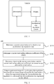
- FIG. 1 is a schematic diagram of an application scenario of a technical solution according to an embodiment of this application.
- the vehicle includes a drive motor, wheels, and an acceleration slip regulation system.
- the drive motor outputs torque to control the wheels
- the acceleration slip regulation system adjusts the drive motor by collecting various signals of the wheels to better control the torque that is output by the drive motor, to perform acceleration slip regulation on the vehicle.
- the vehicle in FIG. 1 includes only the apparatus in this application.
- a person skilled in the art may understand that a structure of the vehicle shown in FIG. 1 constitutes no limitation on the vehicle, and may include more components than those shown in the figure, or combine some components, or have different component arrangements.
- FIG. 2 is a schematic flowchart of an acceleration slip regulation method 100 according to an embodiment of this application. As shown in FIG. 2 , the method 100 may be performed by the acceleration slip regulation system in FIG. 1 . The method 100 includes the following steps.
- the acceleration slip regulation system may identify a TCS control phase TCS phase_i based on an actual torque signal T motor _ i of a drive motor.
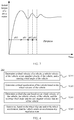
- FIG. 3 is a schematic diagram of a control phase according to an embodiment of this application.
- the control phase TCS phase _ i may include a non-control phase ph0, a TCS torque reduction phase ph1, and a TCS torque increase phase ph2, where i represents any one of wheels. It is assumed that i of a left front wheel is equal to 1, i of a right front wheel is equal to 2, i of a left rear wheel is equal to 3, and i of a right rear wheel is equal to 4.
- control phase in this embodiment of this application is not limited to the foregoing three control phases, and may further include more or fewer control phases. This application is not limited thereto.
- the drive motor is controlled to reduce torque. If the wheels do not slip, the drive motor is controlled to increase torque until a critical point at which the wheels slip is reached.
- a purpose of acceleration slip regulation is to search for this critical point to improve traction, and in addition, to maintain vehicle driving stability.
- the current control phase of the vehicle is determined by using the actual torque signal of the drive motor, and the control phase may also be determined by using another method. This application is not limited thereto.
- the method 100 further includes: determining a wheel acceleration a w _ i and a slip rate ⁇ i that are of the vehicle.
- FIG. 4 is a schematic flowchart of a method 200 for determining a wheel acceleration and a slip rate according to an embodiment of this application. As shown in FIG. 4 , the method 200 includes the following steps.
- S210 Determine a wheel velocity of the vehicle, a vehicle velocity of the vehicle, a yaw angular velocity of the vehicle, and a steering wheel angle of the vehicle.
- the acceleration slip regulation system may obtain the wheel velocity v w_i of the vehicle, the vehicle velocity v x of the vehicle, the yaw angular velocity ⁇ of the vehicle, and the steering wheel angle ⁇ of the vehicle by using a sensor, and may also obtain the foregoing parameters in another manner.
- This application is not limited thereto.
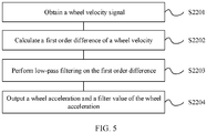
- FIG. 5 is a schematic flowchart of a method for determining a wheel acceleration according to an embodiment of this application. As shown in FIG. 5 , the method for determining a wheel acceleration may be implemented in the following steps:
- FIG. 6 is a schematic flowchart of a method for determining a slip rate according to an embodiment of this application. As shown in FIG. 6 , the method for determining a slip rate may be implemented in the following steps:
- v TH is a predetermined first vehicle velocity threshold
- t w is a wheel track of the vehicle
- L is a wheel base of the vehicle.
- the slip rate is set to 0 if the input vehicle velocity is less than the first vehicle velocity threshold.
- a brand new slip rate estimation method is used to eliminate adverse impact of steering, to help accurately calculate the slip rate.
- the method 200 further includes the following step.
- a TCS entry/exit signal TCS active _ i is determined based on the obtained wheel acceleration a w_i , a wheel acceleration a wF _ i obtained after filtering, the wheel slip rate ⁇ i , driver requirement torque T driver _ i , and a TCS requirement torque signal T TCS _ i . For example, if TCS active _ i is set to "1", it indicates that the vehicle enters the acceleration slip regulation state; or if TCS active _ i is set to "0", it indicates that the vehicle exits from the acceleration slip regulation state.
- the following two conditions are met to determine that the vehicle enters the acceleration slip regulation state.
- a TCS is not started at a previous moment.
- the slip rate is greater than a slip rate threshold obtained when the TCS is started or the wheel acceleration is greater than a wheel acceleration threshold obtained when the TCS is started.
- the following two conditions are met to determine that the vehicle exits from the acceleration slip regulation state.
- a TCS has been started at a previous moment.
- the slip rate is less than a slip rate threshold at which the TCS exits, and exceeds eight program periods; or the driver requirement torque is negative, and exceeds two program periods.
- FIG. 7A and FIG. 7B are a schematic flowchart of a method for determining a current road surface adhesion coefficient and maximum torque allowed by a road surface according to an embodiment of this application. As shown in FIG. 7A and FIG. 7B , the method for determining a current road surface adhesion coefficient of a vehicle and maximum torque allowed by a road surface may be implemented in the following steps.
- a x is a wheel longitudinal acceleration
- a y is a wheel lateral acceleration
- l f is a distance from a center of mass of the vehicle to a front axle
- l r is a distance from the center of mass of the vehicle to a rear axle
- ⁇ is a road surface gradient
- i g is a reducer velocity ratio of the vehicle
- I w is wheel rotation inertia of the vehicle
- r is a wheel radius of the vehicle
- f 0 is a rolling resistance coefficient of the vehicle.
- S330 Determine whether the wheel ground driving force obtained through calculation in S320 is greater than a first driving force threshold, and perform S340 if the wheel ground driving force is greater than the first driving force threshold; or if the wheel ground driving force is less than or equal to the first driving force threshold, output a maximum value of the adhesion coefficient, namely, a second maximum value of the adhesion coefficient.
- the second maximum value of the adhesion coefficient may be 1, or may be another value. This application is not limited thereto.
- ⁇ max_ i is the second maximum value of the adhesion coefficient.
- S340 Determine whether the vehicle enters an acceleration slip regulation state, and if the vehicle does not enter the acceleration slip regulation state, output a maximum value of the adhesion coefficient, namely, a second maximum value of the adhesion coefficient; or perform S350 if the vehicle enters the acceleration slip regulation state.
- the second maximum value of the adhesion coefficient may be 1, or may be another value. This application is not limited thereto.
- the maximum torque allowed by the road surface may be calculated according to Formula (7).
- ⁇ max_ i is the second maximum value of the adhesion coefficient.
- the predetermined adhesion coefficient interval ranges from 0.05 to 1. This application is not limited thereto.
- S354 Determine whether a current control phase of the vehicle is the same as a control phase of the vehicle in a first sampling period, and if the current control phase of the vehicle is the same as the control phase of the vehicle in the first sampling period, output the second maximum value of the adhesion coefficient, where the second maximum value of the adhesion coefficient is the first maximum value of the adhesion coefficient in S353; or perform S355 if the current control phase of the vehicle is different from the control phase of the vehicle in the first sampling period, where the first sampling period is a previous sampling period of a sampling period in which the current control phase is located.
- sampling period is duration for which each program runs on an electronic control unit (Electronic Control Unit, ECU) of the vehicle.
- the electronic control unit may preset a sampling period, for example, preset the sampling period to 10 seconds.
- the ECU may detect the current control phase of the vehicle in a current sampling period, and compare the current control phase with a control phase in the previous sampling period. If the current control phase is the same as the control phase in the previous sampling period, the second maximum value of the adhesion coefficient is output.
- that the second maximum value of the adhesion coefficient is determined based on the actual torque fed back by the drive motor when the vehicle enters the torque reduction phase for the first time includes: calculating the adhesion coefficient by using k times of the actual torque fed back by the drive motor when the torque reduction phase is entered for the first time.
- the second maximum value of the adhesion coefficient is determined based on the actual torque fed back by the drive motor when the vehicle enters the torque reduction phase for the first time, and the maximum torque allowed by the road surface is calculated by using Formula (7), where the first sampling period is the previous sampling period of the sampling period in which the current control phase is located.
- k may be greater than 0 and less than 1, for example, 0.8 or 0.9. This application is not limited thereto.
- processing procedures of S351 to S353 need to be further performed for the adhesion coefficient after the second maximum value of the adhesion coefficient is determined based on the actual torque fed back by the drive motor when the vehicle enters the torque reduction phase for the first time, for example, the adhesion coefficient is calculated by using 0.9 times of the actual torque fed back by the drive motor when the torque reduction phase is entered for the first time, to avoid an excessively large error of the adhesion coefficient.
- an algorithm for identifying the maximum torque allowed by the road surface is used to more accurately identify the maximum torque and the current road surface adhesion coefficient.
- FIG. 8 is a schematic flowchart of a method for determining requirement torque for acceleration slip regulation according to an embodiment of this application. As shown in FIG. 8 , that the requirement torque for the acceleration slip regulation is output based on the maximum torque allowed by the road surface includes the following steps:
- that the feedback torque is determined includes:
- that the feedforward torque is determined includes:
- a process of determining adaptive feedforward torque includes:
- f ( ⁇ i ) is torque modified based on the wheel slip rate.
- the modified torque is calculated based on the wheel slip rate includes:
- the requirement torque for the acceleration slip regulation is a sum of the feedforward torque and the feedback torque.
- the requirement torque for the acceleration slip regulation is determined based on the feedforward torque and the feedback torque includes: calculating final output torque for acceleration slip regulation based on a TCS entry/exit signal TCS active _ i and the sum T FF + FB_i of the feedforward torque T FF_i and the feedback torque T FB_i .
- TCS active_i when TCS active_i is set to "1", it indicates that the vehicle enters the acceleration slip regulation state. In this case, information indicating that the requirement torque T TCS_i for the acceleration slip regulation is T FF + FB_i is output. When TCS active_i is set to "0", it indicates that the vehicle exits from the acceleration slip regulation state. In this case, information indicating that the requirement torque T TCS_i for the acceleration slip regulation is pre-defined maximum torque of the drive motor is output.
- driving torque is calculated in a feedforward and feedback joint control manner.
- a slip rate target value in the feedback control manner is dynamically calculated by using a dynamic value based on a current vehicle velocity and road surface adhesion condition, and a feedback control coefficient in the feedback control manner is also adaptively adjusted based on the current vehicle velocity and road surface condition, to improve system adaptation capability.
- the feedforward control manner is introduced. Requirement torque output to the motor is introduced as a feedforward part (not the driver requirement torque) and the maximum torque is used to limit the feedforward part. In this way, a control system can perform "predetermining" to speed up convergence.
- an adaptive feedforward and feedback joint control method is used to implement acceleration slip regulation, to help enhance robustness and improve a response speed.
- FIG. 9 is a schematic block diagram of a vehicle 400 according to an embodiment of this application.
- the vehicle 400 includes a sensor 410 and an electronic control unit 420.
- the sensor 410 is configured to obtain a current road surface parameter.
- the electronic control unit 420 is configured to determine a current control phase of the vehicle in an acceleration slip regulation state.
- the electronic control unit 420 is further configured to determine a current road surface adhesion coefficient of the vehicle based on the current road surface parameter.
- the electronic control unit 420 is further configured to determine, based on the current control phase and the current road surface adhesion coefficient, maximum torque allowed by a road surface.
- the electronic control unit 420 is further configured to output, to the drive motor 430, requirement torque for acceleration slip regulation based on the maximum torque allowed by the road surface, where the requirement torque for the acceleration slip regulation is used to perform the acceleration slip regulation on the vehicle 400.
- the drive motor 430 may control, based on the requirement torque for the acceleration slip regulation that is output by the electronic control unit 420, a transmission device to control wheels 440 of the vehicle to perform the acceleration slip regulation on the vehicle 400.
- FIG. 10 is a schematic block diagram of the electronic control unit 420.
- the electronic control unit 420 herein is divided into a TCS control phase identification unit 421, a unit 422 for identifying maximum torque allowed by a road surface, and an output torque processing unit 423.
- the TCS control phase identification unit 421 is configured to determine the control phase in which the acceleration slip regulation is performed on the vehicle.
- the unit 422 for identifying maximum torque allowed by a road surface is configured to determine the current road surface adhesion coefficient of the vehicle.
- the unit 422 for identifying maximum torque allowed by a road surface is further configured to determine, based on the control phase and the current road surface adhesion coefficient, the maximum torque allowed by the road surface.
- the output torque processing unit 423 outputs the requirement torque for the acceleration slip regulation based on the maximum torque allowed by the road surface, where the requirement torque for the acceleration slip regulation is used to perform the acceleration slip regulation on the vehicle 400.
- the electronic control unit 420 further includes: a TCS signal processing unit 424, configured to determine a wheel acceleration and a slip rate that are of the vehicle.
- FIG. 11 is a schematic diagram of the TCS signal processing unit 424 according to an embodiment of this application.
- the sensor 410 is further configured to obtain a wheel velocity of the vehicle, a vehicle velocity of the vehicle, a yaw angular velocity of the vehicle, and a steering wheel angle of the vehicle.
- the TCS signal processing unit 424 is specifically configured to:
- the TCS signal processing unit 424 may obtain the wheel velocity of the vehicle, the vehicle velocity of the vehicle, the yaw angular velocity of the vehicle, and the steering wheel angle of the vehicle by using the sensor 410, and may also obtain the foregoing parameters in another manner. This application is not limited thereto.
- the TCS signal processing unit 424 is further configured to:
- the senor 410 is further configured to: obtain the wheel velocity, the vehicle velocity, the steering wheel angle, and the yaw angular velocity that are of the vehicle 400.
- the TCS signal processing unit 424 is further configured to:
- a brand new slip rate estimation method is used to eliminate adverse impact of steering, to help accurately calculate the slip rate.
- the TCS control phase identification unit 421 is further configured to determine, based on the wheel slip rate and/or the wheel acceleration, that the vehicle enters the acceleration slip regulation state.
- the TCS control phase identification unit 421 determines a TCS entry/exit signal based on the obtained wheel acceleration, a wheel acceleration obtained after filtering, the wheel slip rate, driver requirement torque, and a TCS requirement torque signal. For example, if the TCS entry/exit signal is set to "1", it indicates that the vehicle enters the acceleration slip regulation state; or if the TCS entry/exit signal is set to "0", it indicates that the vehicle exits from the acceleration slip regulation state.
- the following two conditions are met to determine that the vehicle enters the acceleration slip regulation state.
- a TCS is not started at a previous moment.
- the slip rate is greater than a slip rate threshold obtained when the TCS is started or the wheel acceleration is greater than a wheel acceleration threshold obtained when the TCS is started.
- the following two conditions are met to determine that the vehicle exits from the acceleration slip regulation state.
- a TCS has been started at a previous moment.
- the slip rate is less than a slip rate threshold at which the TCS exits, and exceeds eight program periods; or the driver requirement torque is negative, and exceeds two program periods.
- FIG. 12 is a schematic diagram of the unit 422 for identifying maximum torque allowed by a road surface according to an embodiment of this application. As shown in FIG. 12 , the unit 422 for identifying maximum torque allowed by a road surface is specifically configured to:
- the maximum value of an adhesion coefficient namely, a second maximum value of the adhesion coefficient is output.
- the maximum torque allowed by the road surface may be calculated according to Formula (7).
- an adhesion coefficient is calculated according to Formula (8).
- Low-pass filtering is performed on the adhesion coefficient obtained through calculation according to Formula (8).
- An adhesion coefficient obtained after the low-pass filtering is limited to a predetermined adhesion coefficient interval.
- a first maximum value of the adhesion coefficient is determined based on the adhesion coefficient obtained after the filtering.
- a current control phase of the vehicle is the same as a control phase of the vehicle in a first sampling period, and if the current control phase of the vehicle is the same as the control phase of the vehicle in the first sampling period, the second maximum value of the adhesion coefficient is output, where the second maximum value of the adhesion coefficient is the first maximum value of the adhesion coefficient.
- the maximum torque allowed by the road surface may be calculated according to Formula (7).
- the first sampling period is a previous sampling period of a sampling period in which the current control phase is located.
- the current control phase of the vehicle is different from the control phase of the vehicle in the first sampling period, it is determined whether the vehicle enters a torque reduction phase for the first time, and if the vehicle does not enter the torque reduction phase for the first time, the second maximum value of the adhesion coefficient is output, where the second maximum value of the adhesion coefficient is the first maximum value of the adhesion coefficient.
- the second maximum value of the adhesion coefficient is determined based on actual torque fed back by a drive motor when the vehicle enters the torque reduction phase for the first time.
- the maximum torque allowed by the road surface may be calculated according to Formula (7).
- that the second maximum value of the adhesion coefficient is determined based on the actual torque fed back by the drive motor when the vehicle enters the torque reduction phase for the first time includes: calculating the adhesion coefficient by using 0.9 times of the actual torque fed back by the drive motor when the torque reduction phase is entered for the first time.
- the second maximum value of the adhesion coefficient is determined based on the actual torque fed back by the drive motor when the vehicle enters the torque reduction phase for the first time, and the maximum torque allowed by the road surface is calculated by using Formula (7).
- the adhesion coefficient may also be calculated based on another number times the actual torque fed back by the drive motor when the vehicle enters the torque reduction phase for the first time, for example, 0.8 times. This application is not limited thereto.
- an algorithm for identifying the maximum torque allowed by the road surface is used to more accurately identify the maximum torque and the current road surface adhesion coefficient.
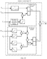
- the vehicle 400 further includes: an adaptive control unit 425, configured to: determine feedback torque based on the second maximum value of the adhesion coefficient; and determine feedforward torque based on the maximum torque allowed by the road surface.
- an adaptive control unit 425 configured to: determine feedback torque based on the second maximum value of the adhesion coefficient; and determine feedforward torque based on the maximum torque allowed by the road surface.
- FIG. 13 is a schematic diagram of the adaptive control unit 425 according to an embodiment of this application. As shown in FIG. 13 , the adaptive control unit 425 is specifically configured to:
- the adaptive control unit 425 is specifically configured to:
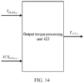
- FIG. 14 is a schematic diagram of the output torque processing unit 423 according to an embodiment of this application. As shown in FIG. 14 , the output torque processing unit 423 is specifically configured to determine the requirement torque for the acceleration slip regulation based on the feedforward torque and the feedback torque.
- the requirement torque for the acceleration slip regulation is a sum of the feedforward torque and the feedback torque.
- the output torque processing unit 423 determines the requirement torque for the acceleration slip regulation based on the feedforward torque and the feedback torque includes: calculating final output torque for acceleration slip regulation based on a TCS entry/exit signal and the sum of the feedforward torque and the feedback torque.
- the TCS entry/exit signal when the TCS entry/exit signal is set to "1", it indicates that the vehicle enters the acceleration slip regulation state. In this case, information indicating that the requirement torque for the acceleration slip regulation is the sum of the feedforward torque and the feedback torque is output. When the TCS entry/exit signal is set to "0", it indicates that the vehicle exits from the acceleration slip regulation state. In this case, information indicating that the requirement torque for the acceleration slip regulation is pre-defined maximum torque of the drive motor is output.
- driving torque is calculated in a feedforward and feedback joint control manner.
- a slip rate target value in the feedback control manner is dynamically calculated by using a dynamic value based on a current vehicle velocity and a road surface adhesion condition, and a feedback control coefficient in the feedback control manner is also adaptively adjusted based on the current vehicle velocity and the road surface condition, to improve system adaptation capability.
- the feedforward control manner is introduced. Requirement torque output to the motor is introduced as a feedforward part (not the driver requirement torque) and the maximum torque is used to limit the feedforward part. In this way, a control system can perform "predetermining" to speed up convergence.
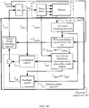
- FIG. 15 is a schematic block diagram of the electronic control unit 420 according to an embodiment of this application.
- the electronic control unit 420 obtains driver requirement torque T driver_i (for example, requirement torque that is of a four-way motor and that is calculated by a VCU), a wheel velocity signal v w _ i (for example, four wheel velocity signals are obtained by the sensor), a vehicle velocity signal v x (for example, there is one vehicle velocity signal, and a vehicle velocity may be estimated in a plurality of manners), a steering wheel angle signal ⁇ (for example, one steering wheel angle signal is obtained by the sensor), a longitudinal acceleration signal a x (for example, one longitudinal acceleration signal is obtained by the sensor), a lateral acceleration signal a y (for example, one lateral acceleration signal is obtained by the sensor), a yaw angular velocity signal ⁇ (for example, one yaw angular velocity signal is obtained by the sensor), and an actual torque signal T motor _ i (for example, driver requirement torque that is
- the sensors applied to the vehicle in this embodiment of this application are standard sensors of the vehicle. Therefore, no additional hardware costs are added.
- an adaptive feedforward and feedback joint control method is used to implement acceleration slip regulation, to help enhance robustness and improve a response speed.
- An embodiment of this application further provides a vehicle, and the vehicle includes:
- T FF _ i is the adaptive feedforward torque
- T dem _ i is the requirement torque received by the drive motor
- T max_ i is the maximum torque allowed by the road surface
- ⁇ 1 is a time constant of a first filter
- ⁇ 2 is a time constant of a second filter
- f ( ⁇ i ) is torque modified based on the wheel slip rate.
- processor is further configured to calculate the modified torque based on the wheel slip rate specifically includes:
- the processor is specifically configured to:
- the processor is specifically configured to:
- the processor is further configured to:
- the senor is further configured to: obtain actual torque fed back by the drive motor of the vehicle.
- the processor is further configured to:
- the processor is further configured to:
- the processor is further configured to:
- the senor is further configured to obtain a road surface gradient.
- the processor is further configured to:
- the senor is further configured to: obtain a wheel velocity of the vehicle, a yaw angular velocity of the vehicle, and a steering wheel angle of the vehicle.
- the processor is further configured to:
- the processor may be the electronic control unit or a part of the electronic control unit.
- the electronic control unit may be a central processing unit (Central Processing Unit, CPU), a network processor (Network Processor, NP), or a combination of a CPU and an NP.
- the electronic control unit may further include a hardware chip.
- the hardware chip may be an application-specific integrated circuit (Application-Specific Integrated Circuit, ASIC), a programmable logic device (Programmable Logic Device, PLD), or a combination thereof.
- the PLD may be a complex programmable logic device (Complex Programmable Logic Device, CPLD), a field-programmable gate array (Field-Programmable Gate Array, FPGA), a generic array logic (Generic Array Logic, GAL), or any combination thereof.
- All or some of the foregoing embodiments may be implemented by using software, hardware, firmware, or any combination thereof.
- all or some of the embodiments may be implemented in a form of a computer program product.
- the computer program product may include one or more computer instructions.
- the computer may be a general-purpose computer, a special-purpose computer, a computer network, or another programmable apparatus.
- the computer instructions may be stored in a computer readable storage medium or may be transmitted from a computer readable storage medium to another computer readable storage medium.
- the computer instructions may be transmitted from a website, computer, server, or data center to another website, computer, server, or data center in a wired (for example, a coaxial cable, an optical fiber, or a digital subscriber (DSL)) or wireless (for example, infrared, radio, or microwave) manner.
- the computer readable storage medium may be any usable medium accessible by the computer, or a data storage device, such as a server or a data center, integrating one or more usable media.
- the usable medium may be a magnetic medium (for example, a floppy disk, a hard disk, or a magnetic disk), an optical medium (for example, a DVD), a semiconductor medium (for example, a solid state disk Solid State Disk (SSD), or the like.
- the disclosed system, apparatus, and method may be implemented in another manner.
- the described apparatus embodiment is merely an example.
- the unit division is merely logical function division. There may be another division manner during actual implementation. For example, a plurality of units or components may be combined or integrated into another system, or some features may be ignored or may not be performed.
- the displayed or discussed mutual couplings or direct couplings or communication connections may be implemented by using some interfaces.
- the indirect couplings or communication connections between the apparatuses or units may be implemented in electronic, mechanical, or another form.
- the units described as separate parts may or may not be physically separate, and parts displayed as units may or may not be physical units, and may be located in one position, or may be distributed on a plurality of network units. Some or all of the units may be selected based on actual requirements to achieve the objectives of the solutions of the embodiments.
- function units in the embodiments of this application may be integrated into one processing unit, or each of the units may exist alone physically, or two or more units may be integrated into one unit.
- the functions When the functions are implemented in a form of a software function unit and sold or used as an independent product, the functions may be stored in a computer readable storage medium. Based on such an understanding, the technical solutions of this application essentially, or the part contributing to the prior art, or some of the technical solutions may be implemented in a form of a software product.
- the computer software product is stored in a storage medium, and includes several instructions for instructing a computer device (which may be a personal computer, a server, a network device, or the like) to perform all or some of the steps of the methods in the embodiments of this application.
- the foregoing storage medium includes any medium that can store program code, such as a USB flash drive, a removable hard disk, a read-only memory, a random access memory, a magnetic disk, or an optical disc.
Landscapes
- Engineering & Computer Science (AREA)
- Transportation (AREA)
- Mechanical Engineering (AREA)
- Automation & Control Theory (AREA)
- Power Engineering (AREA)
- Sustainable Energy (AREA)
- Life Sciences & Earth Sciences (AREA)
- Sustainable Development (AREA)
- Physics & Mathematics (AREA)
- Mathematical Physics (AREA)
- Human Computer Interaction (AREA)
- Electric Propulsion And Braking For Vehicles (AREA)
- Control Of Driving Devices And Active Controlling Of Vehicle (AREA)
Abstract
Description
- This application claims priority to Chinese Patent Application No.
201710385375.8 - This application relates to the vehicle field, and more specifically, to an acceleration slip regulation method and a vehicle.
- A four-wheel independent drive electric vehicle has four independent controllable power sources, can control a driving force quickly and accurately based on a current vehicle and a road surface condition, and has become a development trend for a next-generation electric vehicle.
- In the national 973/863 program, a four-wheel independent drive key technology, especially a kinetic control technology (ABS/ASR/ESC) has been listed as a major project for key funding for several consecutive years. In the "national new energy vehicle major project" in 2017, the four-wheel independent drive key technology was listed again as a major common key technology for key funding. A technical reserve is intensely performed on the four-wheel independent drive key technology in corporations such as China FAW, BYD, and BAIC at home, and Japanese Toyota, German Volkswagen, and General Motors at abroad. It can be learned that in the near future, the four-wheel independent drive-related technology definitely becomes a hot spot in the vehicle industry.
- A vehicle acceleration slip regulation (Acceleration Slip Regulation, ASR) system, also referred to as a traction control system (Traction Control System, TCS), implements a function of acceleration slip regulation of a drive wheel by controlling torque of the drive wheel. Currently, kinetic control such as acceleration slip regulation on a four-wheel independent drive is mainly in a laboratory research phase, and there is little large-scale real car research. Therefore, the research is not thorough.
- An acceleration slip regulation method mainly includes a logic threshold control method, a PID control method, a fuzzy control method, and the like, and the logic threshold and PID methods are widely used.
- In the prior art, especially for an electric independent four-wheel drive, a conventional acceleration slip regulation system is used, and therefore a response speed is low, control accuracy is low, road surface adaptability is poor, and the like.
- This application provides an acceleration slip regulation method and a vehicle, to help improve a response speed, enhance robustness, and improve control accuracy.
- According to a first aspect, an acceleration slip regulation method is provided, and the method includes: determining a current control phase of a vehicle in an acceleration slip regulation state; determining a current road surface adhesion coefficient of the vehicle; determining, based on the control phase and the current road surface adhesion coefficient, maximum torque allowed by a road surface; and outputting requirement torque for acceleration slip regulation based on the maximum torque allowed by the road surface, where the requirement torque for the acceleration slip regulation is used to perform the acceleration slip regulation on the vehicle.
- In some possible implementations, the determining a current control phase of a vehicle in an acceleration slip regulation state includes: obtaining an actual torque signal of a drive motor of the vehicle; and identifying, based on the actual torque signal of the drive motor, the control phase in which the acceleration slip regulation is performed on the vehicle.
- In some possible implementations, the outputting requirement torque for acceleration slip regulation based on the maximum torque allowed by the road surface includes: determining the requirement torque for the acceleration slip regulation based on the maximum torque allowed by the road surface and an adhesion coefficient of the road surface.
- In this embodiment of this application, the acceleration slip regulation method is used to improve a response speed, enhance robustness, and improve control accuracy.
- With reference to the first aspect, in a first possible implementation of the first aspect, the determining, based on the current control phase and the current road surface adhesion coefficient, maximum torque allowed by a road surface includes: performing filtering on the current road surface adhesion coefficient, and determining a first maximum value of the adhesion coefficient; and if the current control phase of the vehicle is the same as a control phase of the vehicle in a first sampling period, determining, based on a second maximum value of the adhesion coefficient, the maximum torque allowed by the road surface, where the second maximum value of the adhesion coefficient is the first maximum value of the adhesion coefficient, and the first sampling period is a previous sampling period of a sampling period in which the current control phase is located.
- With reference to the first aspect, in a second possible implementation of the first aspect, the determining, based on the current control phase and the current road surface adhesion coefficient, maximum torque allowed by a road surface includes: performing filtering on the current road surface adhesion coefficient, and determining a first maximum value of the adhesion coefficient; and if the current control phase of the vehicle is different from a control phase of the vehicle in a first sampling period, and the vehicle does not enter a torque reduction phase for the first time, determining, based on a second maximum value of the adhesion coefficient, the maximum torque allowed by the road surface, where the second maximum value of the adhesion coefficient is the first maximum value of the adhesion coefficient, the control phase includes the torque reduction phase, and the first sampling period is a previous sampling period of a sampling period in which the current control phase is located.
- With reference to the first or the second possible implementation of the first aspect, in a third possible implementation of the first aspect, the determining a first maximum value of the adhesion coefficient based on the current road surface adhesion coefficient includes: performing filtering on the current road surface adhesion coefficient; limiting a current road surface adhesion coefficient obtained after the filtering to a predetermined adhesion coefficient interval; and determining the first maximum value of the adhesion coefficient based on the current road surface adhesion coefficient obtained after the filtering.
- With reference to the first aspect, in a fourth possible implementation of the first aspect, the method further includes: determining actual torque fed back by the drive motor of the vehicle; and the determining, based on the current control phase and the current road surface adhesion coefficient, maximum torque allowed by a road surface includes: if the current control phase of the vehicle is different from a control phase of the vehicle in a first sampling period, and the vehicle enters a torque reduction phase for the first time, determining a second maximum value of the adhesion coefficient based on the actual torque fed back by the drive motor when the vehicle enters the torque reduction phase for the first time; and determining, based on the second maximum value of the adhesion coefficient, the maximum torque allowed by the road surface, where the control phase includes the torque reduction phase, and the first sampling period is a previous sampling period of a sampling period in which the current control phase is located.
- With reference to any one of the first to the fourth possible implementations of the first aspect, in a fifth possible implementation of the first aspect, the outputting requirement torque for acceleration slip regulation based on the maximum torque allowed by the road surface includes: determining feedback torque based on the second maximum value of the adhesion coefficient; determining feedforward torque based on the maximum torque allowed by the road surface; and determining the requirement torque for the acceleration slip regulation based on the feedforward torque and the feedback torque.
- According to the acceleration slip regulation method in this embodiment of this application, an algorithm for identifying the maximum torque allowed by the road surface is used to accurately identify the maximum torque allowed by the road surface and the current road surface adhesion coefficient.
- With reference to the fifth possible implementation of the first aspect, in a sixth possible implementation of the first aspect, the method further includes: determining a wheel slip rate of the vehicle and a vehicle velocity of the vehicle; and the determining feedback torque based on the second maximum value of the adhesion coefficient includes: determining a first wheel slip rate and a first proportionality coefficient based on the second maximum value of the adhesion coefficient; determining a second wheel slip rate and a second proportionality coefficient based on the vehicle velocity of the vehicle; and determining the feedback torque according to a formula

- With reference to the fifth possible implementation of the first aspect, in a seventh possible implementation of the first aspect, the method further includes: determining requirement torque received by the drive motor of the vehicle; and the determining feedforward torque based on the maximum torque allowed by the road surface includes: determining first torque based on the wheel slip rate; and determining the feedforward torque according to a formula

- According to the acceleration slip regulation method in this embodiment of this application, an adaptive feedforward and feedback joint control method is used to enhance robustness of a system and improve a response speed of the system.
- With reference to any one of the fifth to the seventh possible implementations of the first aspect, in an eighth possible implementation of the first aspect, the requirement torque for the acceleration slip regulation is a sum of the feedforward torque and the feedback torque.
- With reference to any one of the first to the eighth possible implementations of the first aspect, in a ninth possible implementation of the first aspect, before the determining a current road surface adhesion coefficient, the method further includes: obtaining a road surface gradient; determining a wheel vertical load of the vehicle based on the road surface gradient; and determining the wheel ground driving force based on the wheel vertical load; and the determining a current road surface adhesion coefficient includes: determining the current road surface adhesion coefficient based on the wheel ground driving force.
- With reference to the ninth possible implementation of the first aspect, in a tenth possible implementation of the first aspect, the determining the wheel ground driving force based on the wheel vertical load includes: determining the wheel ground driving force of the vehicle according to a formula

- With reference to the tenth possible implementation of the first aspect, in an eleventh possible implementation of the first aspect, the determining the current road surface adhesion coefficient based on the wheel ground driving force includes: determining the current road surface adhesion coefficient according to a formula

- With reference to the eleventh possible implementation of the first aspect, in a twelfth possible implementation of the first aspect, the determining maximum torque allowed by a road surface includes: determining, according to a formula

- With reference to any one of the first aspect, or the first to the twelfth possible implementations of the first aspect, in a thirteenth possible implementation of the first aspect, before the control phase in which the acceleration slip regulation is performed on the vehicle is determined, the method further includes: determining a wheel velocity of the vehicle, a yaw angular velocity of the vehicle, and a steering wheel angle of the vehicle; determining a wheel acceleration of the vehicle based on the wheel velocity of the vehicle; determining the wheel slip rate based on the wheel velocity of the vehicle, the vehicle velocity of the vehicle, and the steering wheel angle and the yaw angular velocity that are of the vehicle; and determining, based on the wheel slip rate and/or the wheel acceleration, that the vehicle enters the acceleration slip regulation state.
- According to the acceleration slip regulation method in this embodiment of this application, impact of vehicle steering on calculation is considered during the calculation of the slip rate, so that the slip rate is accurately calculated during straight driving, and can also be accurately calculated during turning driving.
- With reference to the thirteenth possible implementation of the first aspect, in a fourteenth possible implementation of the first aspect, the determining the wheel slip rate of the vehicle based on the wheel velocity of the vehicle, the vehicle velocity of the vehicle, and the steering wheel angle and the yaw angular velocity that are of the vehicle includes: determining the wheel slip rate according to a formula

- According to a second aspect, a vehicle is provided, and the vehicle includes: an electronic control unit, configured to determine a current control phase of the vehicle in an acceleration slip regulation state; and a sensor, configured to obtain a current road surface parameter. The electronic control unit is further configured to determine a current road surface adhesion coefficient of the vehicle based on the current road surface parameter. The electronic control unit is further configured to determine, based on the current control phase and the current road surface adhesion coefficient, maximum torque allowed by a road surface. The electronic control unit is further configured to output, to the drive motor, requirement torque for acceleration slip regulation based on the maximum torque allowed by the road surface, where the requirement torque for the acceleration slip regulation is used to perform the acceleration slip regulation on the vehicle.
- In some possible implementations, the electronic control unit is specifically configured to: obtain an actual torque signal of the drive motor of the vehicle; and identify, based on the actual torque signal of the drive motor, the control phase in which the acceleration slip regulation is performed on the vehicle.
- In some possible implementations, the electronic control unit is further configured to determine the requirement torque for the acceleration slip regulation based on the maximum torque allowed by the road surface and an adhesion coefficient of the road surface.
- The vehicle in this embodiment of this application is used to improve a response speed, enhance robustness, and improve control accuracy.
- With reference to the second aspect, in a first possible implementation of the second aspect, the electronic control unit is specifically configured to: perform filtering on the current road surface adhesion coefficient, and determine a first maximum value of the adhesion coefficient; and if the current control phase of the vehicle is the same as a control phase of the vehicle in a first sampling period, determine, based on a second maximum value of the adhesion coefficient, the maximum torque allowed by the road surface, where the second maximum value of the adhesion coefficient is the first maximum value of the adhesion coefficient, and the first sampling period is a previous sampling period of a sampling period in which the current control phase is located.
- With reference to the second aspect, in a second possible implementation of the second aspect, the electronic control unit is specifically configured to: determine a first maximum value of the adhesion coefficient based on the current road surface adhesion coefficient; and if the current control phase of the vehicle is different from a control phase of the vehicle in a first sampling period, and the vehicle does not enter a torque reduction phase for the first time, determine, based on a second maximum value of the adhesion coefficient, the maximum torque allowed by the road surface, where the second maximum value of the adhesion coefficient is the first maximum value of the adhesion coefficient, the control phase includes the torque reduction phase, and the first sampling period is a previous sampling period of a sampling period in which the current control phase is located.
- With reference to the first or the second possible implementation of the second aspect, in a third possible implementation of the second aspect, the electronic control unit is further configured to: perform filtering on the current road surface adhesion coefficient; limit a current road surface adhesion coefficient obtained after the filtering to a predetermined adhesion coefficient interval; and determine the first maximum value of the adhesion coefficient based on the current road surface adhesion coefficient obtained after the filtering.
- With reference to the second aspect, in a fourth possible implementation of the second aspect, the sensor is further configured to obtain actual torque fed back by the drive motor of the vehicle. The electronic control unit is further configured to: if the current control phase of the vehicle is different from a control phase of the vehicle in a first sampling period, and the vehicle enters a torque reduction phase for the first time, determine a second maximum value of the adhesion coefficient based on the actual torque fed back by the drive motor when the vehicle enters the torque reduction phase for the first time; and determine, based on the second maximum value of the adhesion coefficient, the maximum torque allowed by the road surface, where the first sampling period is a previous sampling period of a sampling period in which the current control phase is located.
- With reference to any one of the first to the fourth possible implementations of the second aspect, in a fifth possible implementation of the second aspect, the output torque processing unit is specifically configured to: determine feedback torque based on the second maximum value of the adhesion coefficient; determine feedforward torque based on the maximum torque allowed by the road surface; and determine the requirement torque for the acceleration slip regulation based on the feedforward torque and the feedback torque.
- According to the acceleration slip regulation apparatus in this embodiment of this application, an algorithm for identifying the maximum torque allowed by the road surface is used to accurately identify the maximum torque allowed by the road surface and the current road surface adhesion coefficient.
- With reference to the fifth possible implementation of the second aspect, in a sixth possible implementation of the second aspect, the sensor is further configured to obtain a wheel slip rate of the vehicle and a vehicle velocity of the vehicle. The electronic control unit is specifically configured to: determine a first wheel slip rate and a first proportionality coefficient based on the second maximum value of the adhesion coefficient; determine a second wheel slip rate and a second proportionality coefficient based on the vehicle velocity of the vehicle; and determine the feedback torque according to a formula TFB_i =max(0,(λi-(λ 0_i (vx)+λ 0_i (µ max_i )))(Kp _i (vx)+Kp_i (µ max_i ))), where TFB_i is the feedback torque; i represents any one of wheels of the vehicle, and the wheels of the vehicle include a left front wheel, a right front wheel, a left rear wheel, and a right rear wheel; λi is the wheel slip rate of the vehicle; µ max_i is the second maximum value of the adhesion coefficient; vx is the vehicle velocity of the vehicle; λ 0_i (µ max_i ) is the first wheel slip rate; λ 0_i (vx) is the second wheel slip rate; K p_i (µ max_i ) is the first proportionality coefficient; and K p_i (vx) is the second proportionality coefficient.
- With reference to the fifth possible implementation of the second aspect, in a seventh possible implementation of the second aspect, the sensor is further configured to obtain requirement torque received by the drive motor of the vehicle. The electronic control unit is specifically configured to: determine first torque based on the wheel slip rate; and determine the feedforward torque according to a formula

- According to the vehicle in this embodiment of this application, an adaptive feedforward and feedback joint control method is used to implement acceleration slip regulation, to help enhance robustness and improve a response speed.
- With reference to any one of the fifth to the seventh possible implementations of the second aspect, in an eighth possible implementation of the second aspect, the requirement torque for the acceleration slip regulation is a sum of the feedforward torque and the feedback torque.
- With reference to any one of the first to the eighth possible implementations of the second aspect, in a ninth possible implementation of the second aspect, the sensor is further configured to obtain a road surface gradient. The electronic control unit is further configured to: determine a wheel vertical load of the vehicle based on the road surface gradient; determine the wheel ground driving force based on the wheel vertical load; and determine the current road surface adhesion coefficient based on the wheel ground driving force.
- With reference to the ninth possible implementation of the second aspect, in a tenth possible implementation of the second aspect, the electronic control unit is specifically configured to determine the wheel ground driving force of the vehicle according to a formula

- With reference to the tenth possible implementation of the second aspect, in an eleventh possible implementation of the second aspect, the electronic control unit is specifically configured to determine the current road surface adhesion coefficient according to a formula
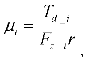
- With reference to the eleventh possible implementation of the second aspect, in a twelfth possible implementation of the second aspect, the electronic control unit is specifically configured to determine, according to a formula

- With reference to any one of the second aspect, or the first to the twelfth possible implementations of the second aspect, in a thirteenth possible implementation of the second aspect, the sensor is further configured to obtain a wheel velocity of the vehicle, a yaw angular velocity of the vehicle, and a steering wheel angle of the vehicle. The electronic control unit is further configured to: determine a wheel acceleration of the vehicle based on the wheel velocity of the vehicle; determine the wheel slip rate based on the wheel velocity of the vehicle, the vehicle velocity of the vehicle, and the steering wheel angle and the yaw angular velocity that are of the vehicle; and determine, based on the wheel slip rate and/or the wheel acceleration, that the vehicle enters the acceleration slip regulation state.
- According to the vehicle in this embodiment of this application, impact of vehicle steering on calculation is considered during the calculation of the slip rate, so that the slip rate is accurately calculated during straight driving, and can also be accurately calculated during turning driving.
- With reference to the thirteenth possible implementation of the second aspect, in a fourteenth possible implementation of the second aspect, the electronic control unit is specifically configured to determine the wheel slip rate according to a formula

- According to a third aspect, a computer readable storage medium is provided, and includes an instruction. When running on a computer, the computer readable storage medium enables the computer to perform the method according to the foregoing aspects.
- According to a fourth aspect, a computer program product is provided. When running on a computer, the computer program product enables the computer to perform the method according to the foregoing aspects.
- According to a fifth aspect, an acceleration slip regulation method is provided, and the method includes: determining a current control phase of a vehicle in an acceleration slip regulation state; determining a current road surface adhesion coefficient of the vehicle; determining, based on the current control phase and the current road surface adhesion coefficient, maximum torque allowed by a road surface; obtaining requirement torque received by a drive motor of the vehicle and a wheel slip rate of the vehicle; and outputting adaptive feedforward torque for acceleration slip regulation based on the maximum torque allowed by the road surface, the requirement torque, and the wheel slip rate, where the adaptive feedforward torque is used to perform the acceleration slip regulation on the vehicle.
- With reference to the fifth aspect, in a first possible implementation of the fifth aspect, the outputting adaptive feedforward torque for acceleration slip regulation based on the maximum torque allowed by the road surface, the requirement torque, and the wheel slip rate includes: determining the adaptive feedforward torque according to a formula

- With reference to the first possible implementation of the fifth aspect, in a second possible implementation of the fifth aspect, that the modified torque is calculated based on the wheel slip rate includes: determining, based on the actual wheel slip rate, whether the vehicle returns to a stable area; if the vehicle returns to the stable area, starting a stable timer; and calculating the modified torque based on a time length recorded by the counter.
- According to a sixth aspect, a vehicle is provided, and the vehicle includes: a sensor, configured to obtain a current road surface parameter, requirement torque received by a drive motor of the vehicle, and a wheel slip rate of the vehicle; and a processor, configured to: determine a current control phase of the vehicle in an acceleration slip regulation state; determine a current road surface adhesion coefficient of the vehicle based on the current road surface parameter; determine, based on the current control phase and the current road surface adhesion coefficient, maximum torque allowed by a road surface; and output adaptive feedforward torque for acceleration slip regulation based on the maximum torque allowed by the road surface, the requirement torque, and the wheel slip rate, where the adaptive feedforward torque is used to perform the acceleration slip regulation on the vehicle.
- In some possible implementations, the processor is the electronic control unit in the second aspect.
- With reference to the sixth aspect, in a first possible implementation of the sixth aspect, the processor is configured to: calculate the adaptive feedforward torque according to the following formula:

- With reference to the first possible implementation of the sixth aspect, in a second possible implementation of the sixth aspect, that the processor is further configured to calculate the modified torque based on the wheel slip rate specifically includes: determining, based on the actual wheel slip rate, whether the vehicle returns to a stable area; if the vehicle returns to the stable area, starting a stable timer; and calculating the modified torque based on a time length recorded by the counter.
-
-
FIG. 1 is a schematic diagram of an application scenario of a technical solution according to an embodiment of this application; -
FIG. 2 is a schematic flowchart of an acceleration slip regulation method according to an embodiment of this application; -
FIG. 3 is a schematic diagram of a control phase according to an embodiment of this application; -
FIG. 4 is a schematic flowchart of a method for determining a wheel acceleration and a slip rate according to an embodiment of this application; -
FIG. 5 is a schematic flowchart of a method for determining a wheel acceleration according to an embodiment of this application; -
FIG. 6 is a schematic flowchart of a method for determining a slip rate according to an embodiment of this application; -
FIG. 7A andFIG. 7B are a schematic flowchart of a method for determining a current road surface adhesion coefficient and maximum torque allowed by a road surface according to an embodiment of this application; -
FIG. 8 is a schematic flowchart of a method for determining requirement torque for acceleration slip regulation according to an embodiment of this application; -
FIG. 9 is a schematic block diagram of a vehicle according to an embodiment of this application; -
FIG. 10 is a schematic block diagram of an electronic control unit in a vehicle according to an embodiment of this application; -
FIG. 11 is a schematic diagram of a TCS signal processing unit according to an embodiment of this application; -
FIG. 12 is a schematic diagram of a unit for identifying maximum torque allowed by a road surface according to an embodiment of this application; -
FIG. 13 is a schematic diagram of an adaptive control unit according to an embodiment of this application; -
FIG. 14 is a schematic diagram of an output torque processing unit according to an embodiment of this application; and -
FIG. 15 is another schematic block diagram of an electronic control unit according to an embodiment of this application. - The following describes technical solutions in this application with reference to the accompanying drawings.
- Embodiments of this application are applicable to various vehicles on which acceleration slip regulation needs to be performed.
FIG. 1 is a schematic diagram of an application scenario of a technical solution according to an embodiment of this application. As shown inFIG. 1 , the vehicle includes a drive motor, wheels, and an acceleration slip regulation system. The drive motor outputs torque to control the wheels, and the acceleration slip regulation system adjusts the drive motor by collecting various signals of the wheels to better control the torque that is output by the drive motor, to perform acceleration slip regulation on the vehicle. - It should be understood that the vehicle in
FIG. 1 includes only the apparatus in this application. A person skilled in the art may understand that a structure of the vehicle shown inFIG. 1 constitutes no limitation on the vehicle, and may include more components than those shown in the figure, or combine some components, or have different component arrangements. -
FIG. 2 is a schematic flowchart of an accelerationslip regulation method 100 according to an embodiment of this application. As shown inFIG. 2 , themethod 100 may be performed by the acceleration slip regulation system inFIG. 1 . Themethod 100 includes the following steps. - S110. Determine a current control phase of a vehicle in an acceleration slip regulation state.
- Specifically, the acceleration slip regulation system may identify a TCS control phase TCSphase_i based on an actual torque signal T motor_i of a drive motor.
FIG. 3 is a schematic diagram of a control phase according to an embodiment of this application. The control phase TCS phase_i may include a non-control phase ph0, a TCS torque reduction phase ph1, and a TCS torque increase phase ph2, where i represents any one of wheels. It is assumed that i of a left front wheel is equal to 1, i of a right front wheel is equal to 2, i of a left rear wheel is equal to 3, and i of a right rear wheel is equal to 4. - It should be understood that the control phase in this embodiment of this application is not limited to the foregoing three control phases, and may further include more or fewer control phases. This application is not limited thereto.
- It should be further understood that stability of the wheels of the vehicle is reflected in the control phase. If the wheels slip, the drive motor is controlled to reduce torque. If the wheels do not slip, the drive motor is controlled to increase torque until a critical point at which the wheels slip is reached. A purpose of acceleration slip regulation is to search for this critical point to improve traction, and in addition, to maintain vehicle driving stability.
- It should be further understood that in the acceleration slip regulation method in this embodiment of this application, the current control phase of the vehicle is determined by using the actual torque signal of the drive motor, and the control phase may also be determined by using another method. This application is not limited thereto.
- Optionally, before the control phase in which the acceleration slip regulation is performed on the vehicle is determined, the
method 100 further includes: determining a wheel acceleration a w_i and a slip rate λi that are of the vehicle. -
FIG. 4 is a schematic flowchart of amethod 200 for determining a wheel acceleration and a slip rate according to an embodiment of this application. As shown inFIG. 4 , themethod 200 includes the following steps. - S210. Determine a wheel velocity of the vehicle, a vehicle velocity of the vehicle, a yaw angular velocity of the vehicle, and a steering wheel angle of the vehicle.
- Specifically, the acceleration slip regulation system may obtain the wheel velocity vw_i of the vehicle, the vehicle velocity vx of the vehicle, the yaw angular velocity ψ of the vehicle, and the steering wheel angle δ of the vehicle by using a sensor, and may also obtain the foregoing parameters in another manner. This application is not limited thereto.
- S220. Determine a wheel acceleration of the vehicle based on the wheel velocity of the vehicle.
-
FIG. 5 is a schematic flowchart of a method for determining a wheel acceleration according to an embodiment of this application. As shown inFIG. 5 , the method for determining a wheel acceleration may be implemented in the following steps: - S2201. Obtain a wheel velocity signal.
- S2202. Calculate a first order difference of the wheel velocity.
- S2203. Perform low-pass filtering on a wheel velocity obtained after the first order difference.
- S2204. Output the wheel acceleration and a filter value awF_i of the wheel acceleration.
- S230. Determine the wheel slip rate based on the wheel velocity of the vehicle, the vehicle velocity of the vehicle, and the steering wheel angle and the yaw angular velocity that are of the vehicle.
-
FIG. 6 is a schematic flowchart of a method for determining a slip rate according to an embodiment of this application. As shown inFIG. 6 , the method for determining a slip rate may be implemented in the following steps: - S2301. Input the wheel velocity, the vehicle velocity, the steering wheel angle, and the yaw angular velocity.
- S2302. Determine whether the vehicle velocity is greater than a first vehicle velocity threshold, and perform S2303 if the vehicle velocity is greater than the first vehicle velocity threshold; or perform S2304 if the vehicle velocity is less than or equal to the first vehicle velocity threshold.
- S2303. Calculate the slip rate according to Formula (1):

- Herein, vTH is a predetermined first vehicle velocity threshold, tw is a wheel track of the vehicle, and L is a wheel base of the vehicle.
- S2304. Set the slip rate to a first slip rate threshold.
- For example, the slip rate is set to 0 if the input vehicle velocity is less than the first vehicle velocity threshold.
- S2305. Perform low-pass filtering on the slip rate in S2303 or S2304.
- S2306. Calculate a first order difference of a slip rate obtained after the filtering.
- S2307. Perform low-pass filtering on a slip rate obtained after the first order difference.
- S2308. Output the slip rate, a filter value λF_i of the slip rate, and a filter valueof a change rate of the slip rate.

- According to the acceleration slip regulation method in this embodiment of this application, a brand new slip rate estimation method is used to eliminate adverse impact of steering, to help accurately calculate the slip rate.
- Optionally, before the control phase in which the acceleration slip regulation is performed on the vehicle is determined, the
method 200 further includes the following step. - S240. Determine, based on the wheel slip rate and/or the wheel acceleration, that the vehicle enters an acceleration slip regulation state.
- Specifically, a TCS entry/exit signal TCS active_i is determined based on the obtained wheel acceleration aw_i , a wheel acceleration a wF_i obtained after filtering, the wheel slip rate λi , driver requirement torque T driver_i , and a TCS requirement torque signal T TCS_i . For example, if TCS active_i is set to "1", it indicates that the vehicle enters the acceleration slip regulation state; or if TCS active_i is set to "0", it indicates that the vehicle exits from the acceleration slip regulation state.
- Optionally, the following two conditions are met to determine that the vehicle enters the acceleration slip regulation state.
- A TCS is not started at a previous moment.
- The slip rate is greater than a slip rate threshold obtained when the TCS is started or the wheel acceleration is greater than a wheel acceleration threshold obtained when the TCS is started.
- Optionally, the following two conditions are met to determine that the vehicle exits from the acceleration slip regulation state.
- A TCS has been started at a previous moment.
- The slip rate is less than a slip rate threshold at which the TCS exits, and exceeds eight program periods; or the driver requirement torque is negative, and exceeds two program periods.
- It should be understood that before it is determined that the vehicle enters the acceleration slip regulation state, the driver requirement torque Tdriver_i and the TCS requirement torque signal TTCS_i need to be further obtained.
- S120. Determine a current road surface adhesion coefficient of the vehicle.
- S130. Determine, based on the control phase and the current road surface adhesion coefficient, maximum torque allowed by a road surface.
-
FIG. 7A andFIG. 7B are a schematic flowchart of a method for determining a current road surface adhesion coefficient and maximum torque allowed by a road surface according to an embodiment of this application. As shown inFIG. 7A andFIG. 7B , the method for determining a current road surface adhesion coefficient of a vehicle and maximum torque allowed by a road surface may be implemented in the following steps. - S310. Calculate a wheel vertical load according to Formulas (2), (3), (4), and (5):



- Herein, ax is a wheel longitudinal acceleration, ay is a wheel lateral acceleration, lf is a distance from a center of mass of the vehicle to a front axle, lr is a distance from the center of mass of the vehicle to a rear axle, and α is a road surface gradient.
- S320. Calculate a wheel ground driving force according to Formula (6):

- Herein, ig is a reducer velocity ratio of the vehicle, Iw is wheel rotation inertia of the vehicle, r is a wheel radius of the vehicle, and f 0 is a rolling resistance coefficient of the vehicle.
- S330. Determine whether the wheel ground driving force obtained through calculation in S320 is greater than a first driving force threshold, and perform S340 if the wheel ground driving force is greater than the first driving force threshold; or if the wheel ground driving force is less than or equal to the first driving force threshold, output a maximum value of the adhesion coefficient, namely, a second maximum value of the adhesion coefficient.
- It should be understood that the second maximum value of the adhesion coefficient may be 1, or may be another value. This application is not limited thereto.
- Optionally, after the maximum value of the adhesion coefficient, namely, the first maximum value of the adhesion coefficient is output, the maximum torque allowed by the road surface may be calculated according to Formula (7):

- Herein, µ max_i is the second maximum value of the adhesion coefficient.
- S340. Determine whether the vehicle enters an acceleration slip regulation state, and if the vehicle does not enter the acceleration slip regulation state, output a maximum value of the adhesion coefficient, namely, a second maximum value of the adhesion coefficient; or perform S350 if the vehicle enters the acceleration slip regulation state.
- It should be understood that the second maximum value of the adhesion coefficient may be 1, or may be another value. This application is not limited thereto.
- Optionally, after the maximum value of the adhesion coefficient, namely, the second maximum value of the adhesion coefficient is output, the maximum torque allowed by the road surface may be calculated according to Formula (7). In this case, µ max_i is the second maximum value of the adhesion coefficient.
- S350. If the vehicle enters the acceleration slip regulation state, calculate a current road surface adhesion coefficient according to Formula (8):

- S351. Perform low-pass filtering on the current road surface adhesion coefficient obtained through calculation in S350.
- S352. Limit an adhesion coefficient obtained after the low-pass filtering to a predetermined current road surface adhesion coefficient interval.
- Optionally, the predetermined adhesion coefficient interval ranges from 0.05 to 1. This application is not limited thereto.
- S353. Determine a first maximum value of the adhesion coefficient based on the current road surface adhesion coefficient obtained after the filtering.
- S354. Determine whether a current control phase of the vehicle is the same as a control phase of the vehicle in a first sampling period, and if the current control phase of the vehicle is the same as the control phase of the vehicle in the first sampling period, output the second maximum value of the adhesion coefficient, where the second maximum value of the adhesion coefficient is the first maximum value of the adhesion coefficient in S353; or perform S355 if the current control phase of the vehicle is different from the control phase of the vehicle in the first sampling period, where the first sampling period is a previous sampling period of a sampling period in which the current control phase is located.
- It should be understood that if the current control phase of the vehicle is the same as the control phase of the vehicle in the first period, the first maximum value of the adhesion coefficient is output, and the maximum torque allowed by the road surface is calculated by using Formula (7).
- It should be further understood that the sampling period is duration for which each program runs on an electronic control unit (Electronic Control Unit, ECU) of the vehicle. The electronic control unit may preset a sampling period, for example, preset the sampling period to 10 seconds. The ECU may detect the current control phase of the vehicle in a current sampling period, and compare the current control phase with a control phase in the previous sampling period. If the current control phase is the same as the control phase in the previous sampling period, the second maximum value of the adhesion coefficient is output.
- S355. If the current control phase of the vehicle is different from the control phase of the vehicle in the first sampling period, determine whether the vehicle enters a torque reduction phase for the first time, and if the vehicle does not enter the torque reduction phase for the first time, output the second maximum value of the adhesion coefficient, where the second maximum value of the adhesion coefficient is the first maximum value of the adhesion coefficient in S353; or perform S356 if the vehicle enters the torque reduction phase for the first time, where the first sampling period is the previous sampling period of the sampling period in which the current control phase is located.
- It should be understood that if the vehicle does not enter the torque reduction phase for the first time, the first maximum value of the adhesion coefficient is output, and the maximum torque allowed by the road surface is calculated by using Formula (7).
- S356. If the vehicle enters the torque reduction phase for the first time, determine the second maximum value of the adhesion coefficient based on actual torque fed back by a drive motor when the vehicle enters the torque reduction phase for the first time.
- Optionally, that the second maximum value of the adhesion coefficient is determined based on the actual torque fed back by the drive motor when the vehicle enters the torque reduction phase for the first time includes: calculating the adhesion coefficient by using k times of the actual torque fed back by the drive motor when the torque reduction phase is entered for the first time.
- It should be understood that if the current control phase of the vehicle is different from the control phase of the vehicle in the first sampling period, and the vehicle enters the torque reduction phase for the first time, the second maximum value of the adhesion coefficient is determined based on the actual torque fed back by the drive motor when the vehicle enters the torque reduction phase for the first time, and the maximum torque allowed by the road surface is calculated by using Formula (7), where the first sampling period is the previous sampling period of the sampling period in which the current control phase is located.
- It should be further understood that k may be greater than 0 and less than 1, for example, 0.8 or 0.9. This application is not limited thereto.
- It should be further understood that processing procedures of S351 to S353 need to be further performed for the adhesion coefficient after the second maximum value of the adhesion coefficient is determined based on the actual torque fed back by the drive motor when the vehicle enters the torque reduction phase for the first time, for example, the adhesion coefficient is calculated by using 0.9 times of the actual torque fed back by the drive motor when the torque reduction phase is entered for the first time, to avoid an excessively large error of the adhesion coefficient.
- According to the acceleration slip regulation method in this embodiment of this application, an algorithm for identifying the maximum torque allowed by the road surface is used to more accurately identify the maximum torque and the current road surface adhesion coefficient.
- S140. Output requirement torque for acceleration slip regulation based on the maximum torque allowed by the road surface, where the requirement torque for the acceleration slip regulation is used to perform the acceleration slip regulation on the vehicle.
-
FIG. 8 is a schematic flowchart of a method for determining requirement torque for acceleration slip regulation according to an embodiment of this application. As shown inFIG. 8 , that the requirement torque for the acceleration slip regulation is output based on the maximum torque allowed by the road surface includes the following steps: - S141. Determine feedback torque based on a second maximum value of the adhesion coefficient.
- Optionally, that the feedback torque is determined includes:
- determining a first wheel slip rate and a first proportionality coefficient based on the second maximum value of the adhesion coefficient;
- determining a second wheel slip rate and a second proportionality coefficient based on the vehicle velocity of the vehicle; and
- determining the feedback torque according to Formula (9), namely, TFB_i =max(0,(λi -(λ 0_i (vx)+λ 0_i (µ max_i )))(Kp_i (vx)+Kp_i (µ max_i ))), where TFB_i is the feedback torque, µ max_i is the second maximum value of the adhesion coefficient, vx is the vehicle velocity of the vehicle, λ 0_i (µ max_i ) is the first wheel slip rate, λ 0_i (vx) is the second wheel slip rate, K p_i (µ max_i ) is the first proportionality coefficient, and K p_i (vx) is the second proportionality coefficient.
- S142. Determine feedforward torque based on the maximum torque allowed by the road surface.
- Optionally, that the feedforward torque is determined includes:
- determining first torque based on the wheel slip rate; and
- determining the feedforward torque according to Formula (10), namely,

- Optionally, a process of determining adaptive feedforward torque includes:
- determining a current control phase of a vehicle in an acceleration slip regulation state;
- determining a current road surface adhesion coefficient of the vehicle;
- determining, based on the current control phase and the current road surface adhesion coefficient, maximum torque allowed by a road surface;
- obtaining requirement torque received by a drive motor of the vehicle and a wheel slip rate of the vehicle; and
- outputting adaptive feedforward torque for acceleration slip regulation based on the maximum torque allowed by the road surface, the requirement torque, and the wheel slip rate, where the adaptive feedforward torque is used to perform the acceleration slip regulation on the vehicle.
- In Formula (10), f(λi ) is torque modified based on the wheel slip rate.
- Optionally, that the modified torque is calculated based on the wheel slip rate includes:
- determining, based on the actual wheel slip rate, whether the vehicle returns to a stable area;
- if the vehicle returns to the stable area, starting a stable timer; and
- calculating the modified torque based on a time length recorded by the counter.
- S143. Determine the requirement torque for the acceleration slip regulation based on the feedforward torque and the feedback torque.
- Optionally, the requirement torque for the acceleration slip regulation is a sum of the feedforward torque and the feedback torque.
- Specifically, that the requirement torque for the acceleration slip regulation is determined based on the feedforward torque and the feedback torque includes: calculating final output torque for acceleration slip regulation based on a TCS entry/exit signal TCS active_i and the sum T FF+FB_i of the feedforward torque TFF_i and the feedback torque TFB_i.
- For example, when TCSactive_i is set to "1", it indicates that the vehicle enters the acceleration slip regulation state. In this case, information indicating that the requirement torque TTCS_i for the acceleration slip regulation is T FF+FB_i is output. When TCSactive_i is set to "0", it indicates that the vehicle exits from the acceleration slip regulation state. In this case, information indicating that the requirement torque TTCS_i for the acceleration slip regulation is pre-defined maximum torque of the drive motor is output.
- It should be understood that a minimum value between final driver requirement torque and the requirement torque for the acceleration slip regulation is transmitted to a motor controller, to avoid interference to normal driving when the acceleration slip regulation is not activated.
- In this embodiment of this application, driving torque is calculated in a feedforward and feedback joint control manner. A slip rate target value in the feedback control manner is dynamically calculated by using a dynamic value based on a current vehicle velocity and road surface adhesion condition, and a feedback control coefficient in the feedback control manner is also adaptively adjusted based on the current vehicle velocity and road surface condition, to improve system adaptation capability. Considering that a specific delay exists in the feedback control manner, the feedforward control manner is introduced. Requirement torque output to the motor is introduced as a feedforward part (not the driver requirement torque) and the maximum torque is used to limit the feedforward part. In this way, a control system can perform "predetermining" to speed up convergence.
- According to the acceleration slip regulation method in this embodiment of this application, an adaptive feedforward and feedback joint control method is used to implement acceleration slip regulation, to help enhance robustness and improve a response speed.
- The foregoing describes in detail the acceleration slip regulation method in the embodiments of this application with reference to
FIG. 2 to FIG. 8 . The following describes in detail a vehicle in embodiments of this application with reference toFIG. 9 to FIG. 15 . -
FIG. 9 is a schematic block diagram of avehicle 400 according to an embodiment of this application. As shown inFIG. 9 , thevehicle 400 includes asensor 410 and anelectronic control unit 420. Thesensor 410 is configured to obtain a current road surface parameter. Theelectronic control unit 420 is configured to determine a current control phase of the vehicle in an acceleration slip regulation state. Theelectronic control unit 420 is further configured to determine a current road surface adhesion coefficient of the vehicle based on the current road surface parameter. Theelectronic control unit 420 is further configured to determine, based on the current control phase and the current road surface adhesion coefficient, maximum torque allowed by a road surface. Theelectronic control unit 420 is further configured to output, to thedrive motor 430, requirement torque for acceleration slip regulation based on the maximum torque allowed by the road surface, where the requirement torque for the acceleration slip regulation is used to perform the acceleration slip regulation on thevehicle 400. - It should be understood that the
drive motor 430 may control, based on the requirement torque for the acceleration slip regulation that is output by theelectronic control unit 420, a transmission device to controlwheels 440 of the vehicle to perform the acceleration slip regulation on thevehicle 400. -
FIG. 10 is a schematic block diagram of theelectronic control unit 420. For ease of description, theelectronic control unit 420 herein is divided into a TCS controlphase identification unit 421, aunit 422 for identifying maximum torque allowed by a road surface, and an outputtorque processing unit 423. - The TCS control
phase identification unit 421 is configured to determine the control phase in which the acceleration slip regulation is performed on the vehicle. - The
unit 422 for identifying maximum torque allowed by a road surface is configured to determine the current road surface adhesion coefficient of the vehicle. - The
unit 422 for identifying maximum torque allowed by a road surface is further configured to determine, based on the control phase and the current road surface adhesion coefficient, the maximum torque allowed by the road surface. - The output
torque processing unit 423 outputs the requirement torque for the acceleration slip regulation based on the maximum torque allowed by the road surface, where the requirement torque for the acceleration slip regulation is used to perform the acceleration slip regulation on thevehicle 400. - Optionally, as shown in
FIG. 10 , theelectronic control unit 420 further includes:
a TCS signal processing unit 424, configured to determine a wheel acceleration and a slip rate that are of the vehicle. -
FIG. 11 is a schematic diagram of the TCS signal processing unit 424 according to an embodiment of this application. As shown inFIG. 11 , thesensor 410 is further configured to obtain a wheel velocity of the vehicle, a vehicle velocity of the vehicle, a yaw angular velocity of the vehicle, and a steering wheel angle of the vehicle. - The TCS signal processing unit 424 is specifically configured to:
- determine the wheel acceleration of the vehicle based on the wheel velocity of the vehicle; and
- determine the wheel slip rate based on the wheel velocity of the vehicle, the vehicle velocity of the vehicle, and the steering wheel angle and the yaw angular velocity that are of the vehicle.
- It should be understood that, the TCS signal processing unit 424 may obtain the wheel velocity of the vehicle, the vehicle velocity of the vehicle, the yaw angular velocity of the vehicle, and the steering wheel angle of the vehicle by using the
sensor 410, and may also obtain the foregoing parameters in another manner. This application is not limited thereto. - Optionally, the TCS signal processing unit 424 is further configured to:
- determine a wheel velocity signal;
- calculate a first order difference of the wheel velocity;
- perform low-pass filtering on a wheel velocity obtained after the first order difference; and
- output the wheel acceleration and a filter value of the wheel acceleration.
- Optionally, the
sensor 410 is further configured to:
obtain the wheel velocity, the vehicle velocity, the steering wheel angle, and the yaw angular velocity that are of thevehicle 400. - The TCS signal processing unit 424 is further configured to:
- determine whether the vehicle velocity is greater than a first vehicle velocity threshold, and if the vehicle velocity is less than or equal to the first vehicle velocity threshold, set the slip rate to a first slip rate threshold; or if the vehicle velocity is greater than the first vehicle velocity threshold, calculate the slip rate according to Formula (1);
- perform low-pass filtering on the slip rate;
- calculate a first order difference of a slip rate obtained after the filtering;
- perform low-pass filtering on a slip rate obtained after the first order difference; and
- output the slip rate, a filter value of the slip rate, and a filter value of a change rate of the slip rate.
- According to the vehicle in this embodiment of this application, a brand new slip rate estimation method is used to eliminate adverse impact of steering, to help accurately calculate the slip rate.
- Optionally, the TCS control
phase identification unit 421 is further configured to determine, based on the wheel slip rate and/or the wheel acceleration, that the vehicle enters the acceleration slip regulation state. - Specifically, the TCS control
phase identification unit 421 determines a TCS entry/exit signal based on the obtained wheel acceleration, a wheel acceleration obtained after filtering, the wheel slip rate, driver requirement torque, and a TCS requirement torque signal. For example, if the TCS entry/exit signal is set to "1", it indicates that the vehicle enters the acceleration slip regulation state; or if the TCS entry/exit signal is set to "0", it indicates that the vehicle exits from the acceleration slip regulation state. - Optionally, the following two conditions are met to determine that the vehicle enters the acceleration slip regulation state.
- A TCS is not started at a previous moment.
- The slip rate is greater than a slip rate threshold obtained when the TCS is started or the wheel acceleration is greater than a wheel acceleration threshold obtained when the TCS is started.
- Optionally, the following two conditions are met to determine that the vehicle exits from the acceleration slip regulation state.
- A TCS has been started at a previous moment.
- The slip rate is less than a slip rate threshold at which the TCS exits, and exceeds eight program periods; or the driver requirement torque is negative, and exceeds two program periods.
- It should be understood that before it is determined that the vehicle enters the acceleration slip regulation state, the driver requirement torque and the TCS requirement torque signal need to be further obtained.
-
FIG. 12 is a schematic diagram of theunit 422 for identifying maximum torque allowed by a road surface according to an embodiment of this application. As shown inFIG. 12 , theunit 422 for identifying maximum torque allowed by a road surface is specifically configured to: - calculate a wheel vertical load according to Formulas (2), (3), (4), and (5);
- calculate a wheel ground driving force according to Formula (6); and
- determine whether the calculated wheel ground driving force is greater than a first driving force threshold, and if the calculated wheel ground driving force is less than or equal to the first driving force threshold, output a maximum value of the adhesion coefficient, namely, a second maximum value of the adhesion coefficient. Optionally, after the maximum value of the adhesion coefficient, namely, the second maximum value of the adhesion coefficient is output, the maximum torque allowed by the road surface may be calculated according to Formula (7).
- If the calculated wheel ground driving force is greater than the first driving force threshold, it is determined whether the vehicle enters an acceleration slip regulation state, and if the vehicle does not enter the acceleration slip regulation state, a maximum value of an adhesion coefficient, namely, a second maximum value of the adhesion coefficient is output. Optionally, after the maximum value of the adhesion coefficient, namely, the second maximum value of the adhesion coefficient is output, the maximum torque allowed by the road surface may be calculated according to Formula (7).
- If the vehicle enters the acceleration slip regulation state, an adhesion coefficient is calculated according to Formula (8).
- Low-pass filtering is performed on the adhesion coefficient obtained through calculation according to Formula (8).
- An adhesion coefficient obtained after the low-pass filtering is limited to a predetermined adhesion coefficient interval.
- A first maximum value of the adhesion coefficient is determined based on the adhesion coefficient obtained after the filtering.
- It is determined whether a current control phase of the vehicle is the same as a control phase of the vehicle in a first sampling period, and if the current control phase of the vehicle is the same as the control phase of the vehicle in the first sampling period, the second maximum value of the adhesion coefficient is output, where the second maximum value of the adhesion coefficient is the first maximum value of the adhesion coefficient. Optionally, after the second maximum value of the adhesion coefficient is output, the maximum torque allowed by the road surface may be calculated according to Formula (7). The first sampling period is a previous sampling period of a sampling period in which the current control phase is located.
- If the current control phase of the vehicle is different from the control phase of the vehicle in the first sampling period, it is determined whether the vehicle enters a torque reduction phase for the first time, and if the vehicle does not enter the torque reduction phase for the first time, the second maximum value of the adhesion coefficient is output, where the second maximum value of the adhesion coefficient is the first maximum value of the adhesion coefficient.
- If the vehicle enters the torque reduction phase for the first time, the second maximum value of the adhesion coefficient is determined based on actual torque fed back by a drive motor when the vehicle enters the torque reduction phase for the first time. Optionally, after the second maximum value of the adhesion coefficient is determined, the maximum torque allowed by the road surface may be calculated according to Formula (7).
- Optionally, that the second maximum value of the adhesion coefficient is determined based on the actual torque fed back by the drive motor when the vehicle enters the torque reduction phase for the first time includes: calculating the adhesion coefficient by using 0.9 times of the actual torque fed back by the drive motor when the torque reduction phase is entered for the first time.
- It should be understood that if the current control phase of the vehicle is different from the control phase of the vehicle in the first sampling period, and the vehicle enters the torque reduction phase for the first time, the second maximum value of the adhesion coefficient is determined based on the actual torque fed back by the drive motor when the vehicle enters the torque reduction phase for the first time, and the maximum torque allowed by the road surface is calculated by using Formula (7).
- It should be further understood that if the vehicle enters the torque reduction phase for the first time, the adhesion coefficient may also be calculated based on another number times the actual torque fed back by the drive motor when the vehicle enters the torque reduction phase for the first time, for example, 0.8 times. This application is not limited thereto.
- According to the vehicle in this embodiment of this application, an algorithm for identifying the maximum torque allowed by the road surface is used to more accurately identify the maximum torque and the current road surface adhesion coefficient.
- Optionally, as shown in
FIG. 9 , thevehicle 400 further includes:
anadaptive control unit 425, configured to: determine feedback torque based on the second maximum value of the adhesion coefficient; and determine feedforward torque based on the maximum torque allowed by the road surface. -
FIG. 13 is a schematic diagram of theadaptive control unit 425 according to an embodiment of this application. As shown inFIG. 13 , theadaptive control unit 425 is specifically configured to: - determine a first wheel slip rate and a first proportionality coefficient based on the second maximum value of the adhesion coefficient;
- determine a second wheel slip rate and a second proportionality coefficient based on the vehicle velocity of the vehicle; and
- determine the feedback torque according to Formula (9).
- Optionally, the
adaptive control unit 425 is specifically configured to: - determine first torque based on the wheel slip rate; and
- determine the feedforward torque according to Formula (10).
-
FIG. 14 is a schematic diagram of the outputtorque processing unit 423 according to an embodiment of this application. As shown inFIG. 14 , the outputtorque processing unit 423 is specifically configured to determine the requirement torque for the acceleration slip regulation based on the feedforward torque and the feedback torque. - Optionally, the requirement torque for the acceleration slip regulation is a sum of the feedforward torque and the feedback torque.
- Specifically, that the output
torque processing unit 423 determines the requirement torque for the acceleration slip regulation based on the feedforward torque and the feedback torque includes: calculating final output torque for acceleration slip regulation based on a TCS entry/exit signal and the sum of the feedforward torque and the feedback torque. - For example, when the TCS entry/exit signal is set to "1", it indicates that the vehicle enters the acceleration slip regulation state. In this case, information indicating that the requirement torque for the acceleration slip regulation is the sum of the feedforward torque and the feedback torque is output. When the TCS entry/exit signal is set to "0", it indicates that the vehicle exits from the acceleration slip regulation state. In this case, information indicating that the requirement torque for the acceleration slip regulation is pre-defined maximum torque of the drive motor is output.
- It should be understood that a minimum value between final driver requirement torque and the requirement torque for the acceleration slip regulation is transmitted to a motor controller, to avoid interference to normal driving when the acceleration slip regulation is not activated.
- In this embodiment of this application, driving torque is calculated in a feedforward and feedback joint control manner. A slip rate target value in the feedback control manner is dynamically calculated by using a dynamic value based on a current vehicle velocity and a road surface adhesion condition, and a feedback control coefficient in the feedback control manner is also adaptively adjusted based on the current vehicle velocity and the road surface condition, to improve system adaptation capability. Considering that a specific delay exists in the feedback control manner, the feedforward control manner is introduced. Requirement torque output to the motor is introduced as a feedforward part (not the driver requirement torque) and the maximum torque is used to limit the feedforward part. In this way, a control system can perform "predetermining" to speed up convergence.
-
FIG. 15 is a schematic block diagram of theelectronic control unit 420 according to an embodiment of this application. As shown inFIG. 15 , theelectronic control unit 420 obtains driver requirement torque Tdriver_i (for example, requirement torque that is of a four-way motor and that is calculated by a VCU), a wheel velocity signal v w_i (for example, four wheel velocity signals are obtained by the sensor), a vehicle velocity signal vx (for example, there is one vehicle velocity signal, and a vehicle velocity may be estimated in a plurality of manners), a steering wheel angle signal δ (for example, one steering wheel angle signal is obtained by the sensor), a longitudinal acceleration signal ax (for example, one longitudinal acceleration signal is obtained by the sensor), a lateral acceleration signal ay (for example, one lateral acceleration signal is obtained by the sensor), a yaw angular velocity signal ψ (for example, one yaw angular velocity signal is obtained by the sensor), and an actual torque signal T motor_i (for example, four actual torque signals are fed back by a motor) of the motor. An output signal is TCS requirement torque TTCS_i . - It should be understood that the sensors applied to the vehicle in this embodiment of this application are standard sensors of the vehicle. Therefore, no additional hardware costs are added.
- According to the vehicle in this embodiment of this application, an adaptive feedforward and feedback joint control method is used to implement acceleration slip regulation, to help enhance robustness and improve a response speed.
- An embodiment of this application further provides a vehicle, and the vehicle includes:
- a sensor, configured to obtain a current road surface parameter, requirement torque received by a drive motor of the vehicle, and a wheel slip rate of the vehicle; and
- a processor, configured to: determine a current control phase of the vehicle in an acceleration slip regulation state; and
- determine a current road surface adhesion coefficient of the vehicle based on the current road surface parameter; determine, based on the current control phase and the current road surface adhesion coefficient, maximum torque allowed by a road surface; and output adaptive feedforward torque for acceleration slip regulation based on the maximum torque allowed by the road surface, the requirement torque, and the wheel slip rate, where the adaptive feedforward torque is used to perform the acceleration slip regulation on the vehicle.
- Optionally, the processor is configured to: calculate the adaptive feedforward torque according to the following formula:

- Herein, T FF_i is the adaptive feedforward torque, T dem_i is the requirement torque received by the drive motor, T max_i is the maximum torque allowed by the road surface, τ 1 is a time constant of a first filter, τ 2 is a time constant of a second filter, and f(λi ) is torque modified based on the wheel slip rate.
- Optionally, that the processor is further configured to calculate the modified torque based on the wheel slip rate specifically includes:
- determining, based on the actual wheel slip rate, whether the vehicle returns to a stable area;
- if the vehicle returns to the stable area, starting a stable timer; and
- calculating the modified torque based on a time length recorded by the counter.
- Optionally, the processor is specifically configured to:
- perform filtering on the current road surface adhesion coefficient, and determine a first maximum value of the adhesion coefficient; and
- if the current control phase of the vehicle is the same as a control phase of the vehicle in a first sampling period, determine, based on a second maximum value of the adhesion coefficient, the maximum torque allowed by the road surface, where the second maximum value of the adhesion coefficient is the first maximum value of the adhesion coefficient; and
- the first sampling period is a previous sampling period of a sampling period in which the current control phase is located.
- Optionally, the processor is specifically configured to:
- perform filtering on the current road surface adhesion coefficient, and determine a first maximum value of the adhesion coefficient; and
- if the current control phase of the vehicle is different from a control phase of the vehicle in a first sampling period, and the vehicle does not enter a torque reduction phase for the first time, determine, based on a second maximum value of the adhesion coefficient, the maximum torque allowed by the road surface, where the second maximum value of the adhesion coefficient is the first maximum value of the adhesion coefficient, and the control phase includes the torque reduction phase; and
- the first sampling period is a previous sampling period of a sampling period in which the current control phase is located.
- Optionally, the processor is further configured to:
- perform filtering on the current road surface adhesion coefficient;
- limit a current road surface adhesion coefficient obtained after the filtering to a predetermined adhesion coefficient interval; and
- determine the first maximum value of the adhesion coefficient based on the current road surface adhesion coefficient obtained after the filtering.
- Optionally, the sensor is further configured to:
obtain actual torque fed back by the drive motor of the vehicle. - The processor is further configured to:
- if the current control phase of the vehicle is different from a control phase of the vehicle in a first sampling period, and the vehicle enters a torque reduction phase for the first time, determine a second maximum value of the adhesion coefficient based on the actual torque fed back by the drive motor when the vehicle enters the torque reduction phase for the first time, where the control phase includes the torque reduction phase; and
- determine, based on the second maximum value of the adhesion coefficient, the maximum torque allowed by the road surface, where
- the first sampling period is a previous sampling period of a sampling period in which the current control phase is located.
- Optionally, the processor is further configured to:
- determine feedback torque based on the second maximum value of the adhesion coefficient; and
- determine requirement torque for the acceleration slip regulation based on the adaptive feedforward torque and the feedback torque, where the requirement torque is used to perform the acceleration slip regulation on the vehicle.
- Optionally, the processor is further configured to:
- determine the wheel slip rate of the vehicle and a vehicle velocity of the vehicle;
- determine a first wheel slip rate and a first proportionality coefficient based on the second maximum value of the adhesion coefficient;
- determine a second wheel slip rate and a second proportionality coefficient based on the vehicle velocity of the vehicle; and
- determine the feedback torque according to a formula TFB_i =max(0,(λi -(λ 0_i (vx)+λ 0_i (µ max_i )))(K p_i (vx)+K p_i (µmax_i ))), where TFB_i is the feedback torque; i represents any one of wheels of the vehicle, and the wheels of the vehicle include a left front wheel, a right front wheel, a left rear wheel, and a right rear wheel; λi is the wheel slip rate of the vehicle; µ max_i is the second maximum value of the adhesion coefficient; vx is the vehicle velocity of the vehicle; λ 0_i (µ max_i ) is the first wheel slip rate; λ 0_i (vx) is the second wheel slip rate; K p_i (µ max_i ) is the first proportionality coefficient; and K p_i (vx) is the second proportionality coefficient.
- Optionally, the sensor is further configured to obtain a road surface gradient.
- The processor is further configured to:
- determine a wheel vertical load of the vehicle based on the road surface gradient;
- determine the wheel ground driving force based on the wheel vertical load; and
- determine the current road surface adhesion coefficient based on the wheel ground driving force.
- Optionally, the sensor is further configured to:
obtain a wheel velocity of the vehicle, a yaw angular velocity of the vehicle, and a steering wheel angle of the vehicle. - The processor is further configured to:
- determine a wheel acceleration of the vehicle based on the wheel velocity of the vehicle;
- determine the wheel slip rate based on the wheel velocity of the vehicle, the vehicle velocity of the vehicle, and the steering wheel angle and the yaw angular velocity that are of the vehicle; and
- determine, based on the wheel slip rate and/or the wheel acceleration, that the vehicle enters the acceleration slip regulation state.
- It should be understood that the processor may be the electronic control unit or a part of the electronic control unit.
- In the embodiments of this application, the electronic control unit may be a central processing unit (Central Processing Unit, CPU), a network processor (Network Processor, NP), or a combination of a CPU and an NP. The electronic control unit may further include a hardware chip. The hardware chip may be an application-specific integrated circuit (Application-Specific Integrated Circuit, ASIC), a programmable logic device (Programmable Logic Device, PLD), or a combination thereof. The PLD may be a complex programmable logic device (Complex Programmable Logic Device, CPLD), a field-programmable gate array (Field-Programmable Gate Array, FPGA), a generic array logic (Generic Array Logic, GAL), or any combination thereof.
- All or some of the foregoing embodiments may be implemented by using software, hardware, firmware, or any combination thereof. When being implemented by using software, all or some of the embodiments may be implemented in a form of a computer program product. The computer program product may include one or more computer instructions. When the computer program instructions are loaded and executed on a computer, the procedures or functions according to the embodiments of this application are all or partially generated. The computer may be a general-purpose computer, a special-purpose computer, a computer network, or another programmable apparatus. The computer instructions may be stored in a computer readable storage medium or may be transmitted from a computer readable storage medium to another computer readable storage medium. For example, the computer instructions may be transmitted from a website, computer, server, or data center to another website, computer, server, or data center in a wired (for example, a coaxial cable, an optical fiber, or a digital subscriber (DSL)) or wireless (for example, infrared, radio, or microwave) manner. The computer readable storage medium may be any usable medium accessible by the computer, or a data storage device, such as a server or a data center, integrating one or more usable media. The usable medium may be a magnetic medium (for example, a floppy disk, a hard disk, or a magnetic disk), an optical medium (for example, a DVD), a semiconductor medium (for example, a solid state disk Solid State Disk (SSD), or the like.
- A person of ordinary skill in the art may be aware that units and algorithm steps in the examples described with reference to the embodiments disclosed in this specification can be implemented by electronic hardware or a combination of computer software and electronic hardware. Whether the functions are performed by hardware or software depends on particular applications and design constraint conditions of the technical solutions. A person skilled in the art may use different methods to implement the described functions for each particular application, but it should not be considered that the implementation goes beyond the scope of this application.
- It may be clearly understood by a person skilled in the art that for the purpose of convenient and brief description, for a detailed working process of the described system, apparatus, and unit, refer to a corresponding process in the foregoing method embodiments. Details are not described herein again.
- In the several embodiments provided in this application, it should be understood that the disclosed system, apparatus, and method may be implemented in another manner. For example, the described apparatus embodiment is merely an example. For example, the unit division is merely logical function division. There may be another division manner during actual implementation. For example, a plurality of units or components may be combined or integrated into another system, or some features may be ignored or may not be performed. In addition, the displayed or discussed mutual couplings or direct couplings or communication connections may be implemented by using some interfaces. The indirect couplings or communication connections between the apparatuses or units may be implemented in electronic, mechanical, or another form.
- The units described as separate parts may or may not be physically separate, and parts displayed as units may or may not be physical units, and may be located in one position, or may be distributed on a plurality of network units. Some or all of the units may be selected based on actual requirements to achieve the objectives of the solutions of the embodiments.
- In addition, function units in the embodiments of this application may be integrated into one processing unit, or each of the units may exist alone physically, or two or more units may be integrated into one unit.
- When the functions are implemented in a form of a software function unit and sold or used as an independent product, the functions may be stored in a computer readable storage medium. Based on such an understanding, the technical solutions of this application essentially, or the part contributing to the prior art, or some of the technical solutions may be implemented in a form of a software product. The computer software product is stored in a storage medium, and includes several instructions for instructing a computer device (which may be a personal computer, a server, a network device, or the like) to perform all or some of the steps of the methods in the embodiments of this application. The foregoing storage medium includes any medium that can store program code, such as a USB flash drive, a removable hard disk, a read-only memory, a random access memory, a magnetic disk, or an optical disc.
- The foregoing descriptions are merely specific implementations of this application, but are not intended to limit the protection scope of this application. Any variation or replacement readily figured out by a person skilled in the art within the technical scope disclosed in this application shall fall within the protection scope of this application. Therefore, the protection scope of this application shall be subject to the protection scope of the claims.
Claims (27)
- An acceleration slip regulation method, comprising:determining a current control phase of a vehicle in an acceleration slip regulation state;determining a current road surface adhesion coefficient of the vehicle;determining, based on the current control phase and the current road surface adhesion coefficient, maximum torque allowed by a road surface;obtaining requirement torque received by a drive motor of the vehicle and a wheel slip rate of the vehicle; andoutputting adaptive feedforward torque for acceleration slip regulation based on the maximum torque allowed by the road surface, the requirement torque, and the wheel slip rate, wherein the adaptive feedforward torque is used to perform the acceleration slip regulation on the vehicle.
- The method according to claim 1, wherein the outputting adaptive feedforward torque for acceleration slip regulation based on the maximum torque allowed by the road surface, the requirement torque, and the wheel slip rate comprises:
determining the adaptive feedforward torque according to a formula
- The method according to claim 2, wherein that the modified torque is calculated based on the wheel slip rate comprises:determining, based on the actual wheel slip rate, whether the vehicle returns to a stable area;if the vehicle returns to the stable area, starting a stable timer; andcalculating the modified torque based on a time length recorded by the counter.
- The method according to any one of claims 1 to 3, wherein the determining, based on the current control phase and the current road surface adhesion coefficient, maximum torque allowed by a road surface comprises:Performing filtering on the current road surface adhesion coefficient, and determining a first maximum value of the adhesion coefficient; andif the current control phase of the vehicle is the same as a control phase of the vehicle in a first sampling period, determining, based on a second maximum value of the adhesion coefficient, the maximum torque allowed by the road surface, wherein the second maximum value of the adhesion coefficient is the first maximum value of the adhesion coefficient; andthe first sampling period is a previous sampling period of a sampling period in which the current control phase is located.
- The method according to any one of claims 1 to 3, wherein the determining, based on the current control phase and the current road surface adhesion coefficient, maximum torque allowed by a road surface comprises:performing filtering on the current road surface adhesion coefficient, and determining a first maximum value of the adhesion coefficient; andif the current control phase of the vehicle is different from a control phase of the vehicle in a first sampling period, and the vehicle does not enter a torque reduction phase for the first time, determining, based on a second maximum value of the adhesion coefficient, the maximum torque allowed by the road surface, wherein the second maximum value of the adhesion coefficient is the first maximum value of the adhesion coefficient, and the control phase comprises the torque reduction phase; andthe first sampling period is a previous sampling period of a sampling period in which the current control phase is located.
- The method according to claim 4 or 5, wherein the performing filtering on the current road surface adhesion coefficient, and determining a first maximum value of the adhesion coefficient comprises:performing filtering on the current road surface adhesion coefficient;limiting a current road surface adhesion coefficient obtained after the filtering to a predetermined adhesion coefficient interval; anddetermining that a maximum value of the current road surface adhesion coefficient obtained after the filtering is the first maximum value of the adhesion coefficient.
- The method according to any one of claims 1 to 3, wherein the method further comprises:determining actual torque fed back by the drive motor of the vehicle; andthe determining, based on the current control phase and the current road surface adhesion coefficient, maximum torque allowed by a road surface comprises:if the current control phase of the vehicle is different from a control phase of the vehicle in a first sampling period, and the vehicle enters a torque reduction phase for the first time, determining a second maximum value of the adhesion coefficient based on the actual torque fed back by the drive motor when the vehicle enters the torque reduction phase for the first time, wherein the control phase comprises the torque reduction phase; anddetermining, based on the second maximum value of the adhesion coefficient, the maximum torque allowed by the road surface, whereinthe first sampling period is a previous sampling period of a sampling period in which the current control phase is located.
- The method according to any one of claims 4 to 7, further comprising:determining feedback torque based on the second maximum value of the adhesion coefficient; anddetermining requirement torque for the acceleration slip regulation based on the feedforward torque and the feedback torque, wherein the requirement torque is used to perform the acceleration slip regulation on the vehicle.
- The method according to claim 8, wherein the method further comprises:determining the wheel slip rate of the vehicle and a vehicle velocity of the vehicle; andthe determining feedback torque based on the second maximum value of the adhesion coefficient comprises:determining a first wheel slip rate and a first proportionality coefficient based on the second maximum value of the adhesion coefficient;determining a second wheel slip rate and a second proportionality coefficient based on the vehicle velocity of the vehicle; anddetermining the feedback torque according to a formula

- The method according to claim 8 or 9, wherein the requirement torque for the acceleration slip regulation is a sum of the feedforward torque and the feedback torque.
- The method according to any one of claims 1 to 10, wherein before the determining a current road surface adhesion coefficient of the vehicle, the method further comprises:obtaining a road surface gradient;determining a wheel vertical load of the vehicle based on the road surface gradient; anddetermining the wheel ground driving force based on the wheel vertical load; andthe determining a current road surface adhesion coefficient of the vehicle comprises:
determining the current road surface adhesion coefficient based on the wheel ground driving force. - The method according to claim 11, wherein the determining the wheel ground driving force based on the wheel vertical load comprises:
determining the wheel ground driving force of the vehicle according to a formula
- The method according to claim 12, wherein the determining the current road surface adhesion coefficient based on the wheel ground driving force comprises:
determining the current road surface adhesion coefficient according to a formula
- The method according to claim 13, wherein the determining maximum torque allowed by a road surface comprises:
determining, according to a formula
- The method according to any one of claims 1 to 14, wherein before the control phase in which the acceleration slip regulation is performed on the vehicle is determined, the method further comprises:determining a wheel velocity of the vehicle, a yaw angular velocity of the vehicle, and a steering wheel angle of the vehicle;determining a wheel acceleration of the vehicle based on the wheel velocity of the vehicle;determining the wheel slip rate based on the wheel velocity of the vehicle, the vehicle velocity of the vehicle, and the steering wheel angle and the yaw angular velocity that are of the vehicle; anddetermining, based on the wheel slip rate and/or the wheel acceleration, that the vehicle enters the acceleration slip regulation state.
- The method according to claim 15, wherein the determining the wheel slip rate of the vehicle based on the wheel velocity of the vehicle, the vehicle velocity of the vehicle, and the steering wheel angle and the yaw angular velocity that are of the vehicle comprises:
determining the wheel slip rate according to a formula
- A vehicle, comprising:a sensor, configured to obtain a current road surface parameter, requirement torque received by a drive motor of the vehicle, and a wheel slip rate of the vehicle; anda processor, configured to: determine a current control phase of the vehicle in an acceleration slip regulation state; anddetermine a current road surface adhesion coefficient of the vehicle based on the current road surface parameter, determine, based on the current control phase and the current road surface adhesion coefficient, maximum torque allowed by a road surface, and output adaptive feedforward torque for acceleration slip regulation based on the maximum torque allowed by the road surface, the requirement torque, and the wheel slip rate, wherein the adaptive feedforward torque is used to perform the acceleration slip regulation on the vehicle.
- The vehicle according to claim 17, wherein
the processor is configured to: calculate the adaptive feedforward torque according to the following formula:
TFF_i is the adaptive feedforward torque, Tdem_i is the requirement torque received by the drive motor, T max_i is the maximum torque allowed by the road surface, τ 1 is a time constant of a first filter, τ 2 is a time constant of a second filter, and f(λi ) is torque modified based on the wheel slip rate. - The vehicle according to claim 18, wherein that the processor is further configured to calculate the modified torque based on the wheel slip rate specifically comprises:determining, based on the actual wheel slip rate, whether the vehicle returns to a stable area;if the vehicle returns to the stable area, starting a stable timer; andcalculating the modified torque based on a time length recorded by the counter.
- The vehicle according to any one of claims 17 to 19, wherein the processor is specifically configured to:perform filtering on the current road surface adhesion coefficient, and determine a first maximum value of the adhesion coefficient; andif the current control phase of the vehicle is the same as a control phase of the vehicle in a first sampling period, determine, based on a second maximum value of the adhesion coefficient, the maximum torque allowed by the road surface, wherein the second maximum value of the adhesion coefficient is the first maximum value of the adhesion coefficient; andthe first sampling period is a previous sampling period of a sampling period in which the current control phase is located.
- The vehicle according to any one of claims 17 to 19, wherein the processor is specifically configured to:perform filtering on the current road surface adhesion coefficient, and determine a first maximum value of the adhesion coefficient; andif the current control phase of the vehicle is different from a control phase of the vehicle in a first sampling period, and the vehicle does not enter a torque reduction phase for the first time, determine, based on a second maximum value of the adhesion coefficient, the maximum torque allowed by the road surface, wherein the second maximum value of the adhesion coefficient is the first maximum value of the adhesion coefficient, and the control phase comprises the torque reduction phase; andthe first sampling period is a previous sampling period of a sampling period in which the current control phase is located.
- The vehicle according to claim 20 or 21, wherein the processor is further configured to:perform filtering on the current road surface adhesion coefficient;limit a current road surface adhesion coefficient obtained after the filtering to a predetermined adhesion coefficient interval; anddetermine the first maximum value of the adhesion coefficient based on the current road surface adhesion coefficient obtained after the filtering.
- The vehicle according to any one of claims 17 to 19, wherein the sensor is further configured to:obtain actual torque fed back by the drive motor of the vehicle; andthe processor is further configured to:if the current control phase of the vehicle is different from a control phase of the vehicle in a first sampling period, and the vehicle enters a torque reduction phase for the first time, determine a second maximum value of the adhesion coefficient based on the actual torque fed back by the drive motor when the vehicle enters the torque reduction phase for the first time, wherein the control phase comprises the torque reduction phase; anddetermine, based on the second maximum value of the adhesion coefficient, the maximum torque allowed by the road surface, whereinthe first sampling period is a previous sampling period of a sampling period in which the current control phase is located.
- The vehicle according to any one of claims 20 to 23, wherein the processor is further configured to:determine feedback torque based on the second maximum value of the adhesion coefficient; anddetermine requirement torque for the acceleration slip regulation based on the adaptive feedforward torque and the feedback torque, wherein the requirement torque is used to perform the acceleration slip regulation on the vehicle.
- The vehicle according to claim 24, wherein the processor is further configured to:determine the wheel slip rate of the vehicle and a vehicle velocity of the vehicle;determine a first wheel slip rate and a first proportionality coefficient based on the second maximum value of the adhesion coefficient;determine a second wheel slip rate and a second proportionality coefficient based on the vehicle velocity of the vehicle; anddetermine the feedback torque according to a formula

- The vehicle according to any one of claims 17 to 25, wherein the sensor is further configured to obtain a road surface gradient; and
the processor is further configured to:determine a wheel vertical load of the vehicle based on the road surface gradient;determine the wheel ground driving force based on the wheel vertical load; anddetermine the current road surface adhesion coefficient based on the wheel ground driving force. - The vehicle according to any one of claims 17 to 26, wherein the sensor is further configured to:obtain a wheel velocity of the vehicle, a yaw angular velocity of the vehicle, and a steering wheel angle of the vehicle; andthe processor is further configured to:determine a wheel acceleration of the vehicle based on the wheel velocity of the vehicle;determine the wheel slip rate based on the wheel velocity of the vehicle, the vehicle velocity of the vehicle, and the steering wheel angle and the yaw angular velocity that are of the vehicle; anddetermine, based on the wheel slip rate and/or the wheel acceleration, that the vehicle enters the acceleration slip regulation state.
Applications Claiming Priority (2)
| Application Number | Priority Date | Filing Date | Title |
|---|---|---|---|
| CN201710385375.8A CN108928261B (en) | 2017-05-26 | 2017-05-26 | Driving anti-skid control method and vehicle |
| PCT/CN2017/118200 WO2018214496A1 (en) | 2017-05-26 | 2017-12-25 | Acceleration slip regulation method and vehicle |
Publications (4)
| Publication Number | Publication Date |
|---|---|
| EP3636479A1 true EP3636479A1 (en) | 2020-04-15 |
| EP3636479A4 EP3636479A4 (en) | 2020-05-20 |
| EP3636479B1 EP3636479B1 (en) | 2023-08-23 |
| EP3636479C0 EP3636479C0 (en) | 2023-08-23 |
Family
ID=64396092
Family Applications (1)
| Application Number | Title | Priority Date | Filing Date |
|---|---|---|---|
| EP17910854.3A Active EP3636479B1 (en) | 2017-05-26 | 2017-12-25 | Acceleration slip regulation method and vehicle |
Country Status (5)
| Country | Link |
|---|---|
| US (1) | US11465628B2 (en) |
| EP (1) | EP3636479B1 (en) |
| JP (1) | JP6980035B2 (en) |
| CN (1) | CN108928261B (en) |
| WO (1) | WO2018214496A1 (en) |
Cited By (1)
| Publication number | Priority date | Publication date | Assignee | Title |
|---|---|---|---|---|
| WO2022189096A1 (en) * | 2021-03-08 | 2022-09-15 | Knorr-Bremse Systeme für Nutzfahrzeuge GmbH | Method for improving the force transmission between the wheel of a vehicle and the road |
Families Citing this family (58)
| Publication number | Priority date | Publication date | Assignee | Title |
|---|---|---|---|---|
| CN111497814A (en) * | 2019-01-29 | 2020-08-07 | 长城汽车股份有限公司 | Vehicle control method and device |
| CN110186842A (en) * | 2019-04-15 | 2019-08-30 | 汉腾汽车有限公司 | A kind of recognition methods of soft surface |
| CN112744086B (en) * | 2019-10-31 | 2022-06-28 | 北京新能源汽车股份有限公司 | Vehicle control method and device and automobile |
| KR102689881B1 (en) * | 2019-11-12 | 2024-08-01 | 현대자동차주식회사 | Eco-friendly vehicle and motor torque control method thereof |
| CN112848915A (en) * | 2019-11-12 | 2021-05-28 | 罗伯特·博世有限公司 | Driving torque controller, control method, automobile and computer storage medium |
| CN110696791B (en) * | 2019-11-21 | 2020-08-21 | 安徽江淮汽车集团股份有限公司 | Electric vehicle energy recovery control method, device, equipment and storage medium |
| US11084471B2 (en) * | 2019-11-22 | 2021-08-10 | Automotive Research & Testing Center | Braking control method according to friction of road surface |
| CN110861647B (en) * | 2019-11-29 | 2021-03-30 | 清华大学 | Road adhesion coefficient estimation method and system for stability control during vehicle steering |
| CN110843783B (en) * | 2019-11-30 | 2022-02-08 | 的卢技术有限公司 | Antiskid pre-control method based on road surface recognition drive |
| CN110843793B (en) * | 2019-12-04 | 2021-11-23 | 苏州智加科技有限公司 | Longitudinal control system and method of automatic driving vehicle based on feedforward control |
| CN111038283A (en) * | 2020-01-15 | 2020-04-21 | 江铃汽车股份有限公司 | Maximum speed limiting method of electric automobile based on acceleration advanced control |
| CN111507019B (en) * | 2020-05-06 | 2022-09-16 | 北京理工大学 | Vehicle mass and road gradient iterative joint estimation method based on MMRLS and SH-STF |
| CN113954820A (en) * | 2020-07-02 | 2022-01-21 | 宝能汽车集团有限公司 | Drive control method, system, device, and storage medium for vehicle |
| CN112026536B (en) * | 2020-09-07 | 2022-06-21 | 中国第一汽车股份有限公司 | Driving anti-skid control method of electric automobile and double-motor four-wheel-drive electric automobile |
| CN112046465B (en) * | 2020-09-11 | 2022-03-18 | 中国第一汽车股份有限公司 | Vehicle stability control method, device, equipment and storage medium |
| CN112277929B (en) * | 2020-11-05 | 2022-03-01 | 中国第一汽车股份有限公司 | Vehicle wheel slip rate control method and device, vehicle and storage medium |
| CN112660110B (en) * | 2020-12-25 | 2023-04-14 | 浙江极氪智能科技有限公司 | Method and device for determining torque limit value |
| CN112455447B (en) | 2021-01-28 | 2021-05-14 | 天津所托瑞安汽车科技有限公司 | Vehicle antiskid control method and device, electronic equipment and medium |
| KR102529526B1 (en) * | 2021-02-16 | 2023-05-04 | 현대자동차주식회사 | System and method for controlling brake |
| CN113580932A (en) * | 2021-07-29 | 2021-11-02 | 江铃汽车股份有限公司 | Maximum speed control method of electric automobile based on road surface identification |
| CN115724370A (en) * | 2021-08-30 | 2023-03-03 | 株式会社艾科赛迪 | Control device for moving body |
| CN113752853B (en) * | 2021-09-14 | 2023-03-24 | 湖南三一华源机械有限公司 | Vehicle driving antiskid control method and system and vehicle |
| CN115042634B (en) * | 2021-10-18 | 2024-11-12 | 长城汽车股份有限公司 | Motor torque control method, device, storage medium and motor controller |
| CN114148340B (en) * | 2021-11-24 | 2024-02-13 | 中国煤炭科工集团太原研究院有限公司 | Wheel slip rate detection method, device, equipment and storage medium for wheel rim drive |
| KR20230107441A (en) | 2022-01-07 | 2023-07-17 | 현대자동차주식회사 | Apparatus for controlling drive force, system having the same and method thereof |
| KR20230117819A (en) * | 2022-02-03 | 2023-08-10 | 한화에어로스페이스 주식회사 | Driving apparatus and driving controlling method |
| KR20230138096A (en) | 2022-03-23 | 2023-10-05 | 현대자동차주식회사 | Method for controlling regenerative braking of vehicle |
| CN114655215B (en) * | 2022-04-29 | 2025-08-22 | 东风汽车有限公司东风日产乘用车公司 | Anti-skid control method, device, equipment and storage medium |
| CN117125053B (en) * | 2022-05-20 | 2025-09-16 | 比亚迪股份有限公司 | Road adhesion coefficient estimation method and torque control method and device |
| CN115489321B (en) * | 2022-08-31 | 2024-02-27 | 重庆赛力斯凤凰智创科技有限公司 | Vehicle energy recovery control method, device, computer equipment and storage medium |
| CN115402117A (en) * | 2022-09-29 | 2022-11-29 | 四川野马汽车股份有限公司 | Control method for output torque change rate limitation of miniature electric automobile |
| TWI845089B (en) * | 2022-12-27 | 2024-06-11 | 財團法人工業技術研究院 | Loading calculation module, vehicle anti-runaway system, vehicle and method using the same |
| US12337851B2 (en) * | 2022-12-27 | 2025-06-24 | Industrial Technology Research Institute | Loading calculation module, vehicle anti-runaway system, vehicle and method using the same |
| CN116101085B (en) * | 2023-03-16 | 2025-07-15 | 岚图汽车科技有限公司 | Pure electric vehicle launch control method, system, device and storage medium |
| CN116588103B (en) * | 2023-04-25 | 2026-01-06 | 东风小康汽车有限公司重庆分公司 | Methods and devices for controlling vehicle movement and intelligent vehicles |
| CN116278813B (en) * | 2023-05-19 | 2023-07-21 | 成都赛力斯科技有限公司 | Request torque control method, device and new energy vehicle based on adhesion coefficient |
| CN116639125A (en) * | 2023-05-31 | 2023-08-25 | 上海拿森汽车电子有限公司 | A vehicle torque control method, device and computer storage medium |
| CN116639097B (en) * | 2023-06-15 | 2025-10-10 | 中国第一汽车股份有限公司 | Vehicle brake slip control method and system |
| CN116443014B (en) * | 2023-06-19 | 2023-10-10 | 广汽埃安新能源汽车股份有限公司 | Anti-skid control method and device for vehicle driving |
| CN116691368A (en) * | 2023-07-17 | 2023-09-05 | 广东高标电子科技有限公司 | Electric vehicle torque control method and device, electric vehicle and storage medium |
| CN116901726B (en) * | 2023-08-07 | 2026-01-20 | 经纬恒润(天津)研究开发有限公司 | Longitudinal vehicle speed driving control method and device |
| CN116890659A (en) * | 2023-08-29 | 2023-10-17 | 北汽福田汽车股份有限公司 | Vehicle and control method, control device and storage medium thereof |
| CN119659635B (en) * | 2023-09-20 | 2025-11-04 | 比亚迪股份有限公司 | Methods and devices for determining road surface adhesion state, vehicle controller and vehicle |
| CN118323098B (en) * | 2024-03-29 | 2025-08-19 | 重庆赛力斯凤凰智创科技有限公司 | Stability control method, device, equipment and storage medium |
| CN118288807B (en) * | 2024-06-06 | 2024-07-30 | 成都赛力斯科技有限公司 | Staged torque control method and device based on slip rate and new energy automobile |
| CN118636891A (en) * | 2024-06-21 | 2024-09-13 | 东风商用车有限公司 | Vehicle control method, device, equipment and readable storage medium on low-adhesion road |
| TWI906959B (en) * | 2024-07-12 | 2025-12-01 | 造隆股份有限公司 | Vehicle skid power control system and control method thereof |
| CN118953038B (en) * | 2024-09-09 | 2025-09-09 | 东风商用车有限公司 | Vehicle brake control method and device, vehicle and computer storage medium |
| CN119017950B (en) * | 2024-09-10 | 2025-11-07 | 广东高标智能科技股份有限公司 | Anti-skid control method and device for power-assisted bicycle, power-assisted bicycle and storage medium |
| CN119037167B (en) * | 2024-10-09 | 2025-09-23 | 岚图汽车科技有限公司 | Jitter suppression method, device, equipment and storage medium based on real-time road perception |
| CN119239550B (en) * | 2024-10-25 | 2026-02-10 | 浙江吉利控股集团有限公司 | Vehicle anti-skid control methods, devices, vehicles, storage media, and software products |
| CN119428634B (en) * | 2024-11-11 | 2025-12-09 | 赛力斯汽车有限公司 | Vehicle running self-adaptive control method, device, equipment and medium |
| CN119388999A (en) * | 2024-11-14 | 2025-02-07 | 上海汽车集团股份有限公司 | A driving control method, device and vehicle |
| CN119863924B (en) * | 2024-12-12 | 2025-12-19 | 同济大学 | A vehicle-cloud integrated method and system for early warning of vehicle driving risks on slippery roads |
| CN119749237B (en) * | 2024-12-28 | 2025-11-21 | 华为技术有限公司 | Display method of speed of electric vehicle, vehicle controller and electric vehicle |
| CN119898208B (en) * | 2025-01-21 | 2025-12-02 | 无锡凌博电子技术股份有限公司 | A method for controlling slippage of electric two-wheeled vehicles considering road surface slippage |
| CN120503795B (en) * | 2025-07-16 | 2025-09-23 | 重庆长安汽车股份有限公司 | Method and device for protruding obstacle up and down of vehicle, medium and product |
| CN120921944B (en) * | 2025-10-15 | 2025-12-26 | 成都赛力斯科技有限公司 | Vehicle anti-skid control methods, devices, systems and vehicles |
Family Cites Families (35)
| Publication number | Priority date | Publication date | Assignee | Title |
|---|---|---|---|---|
| JPH04358955A (en) * | 1991-06-05 | 1992-12-11 | Hitachi Ltd | Safety device of antiskid control system |
| US5927426A (en) | 1996-10-18 | 1999-07-27 | Itt Automotive Inc. | Traction control system for use with four wheel drive vehicles having on-demand transfer cases |
| JP3937524B2 (en) * | 1997-09-30 | 2007-06-27 | トヨタ自動車株式会社 | Vehicle braking / driving force control device |
| US6379281B1 (en) * | 2000-09-08 | 2002-04-30 | Visteon Global Technologies, Inc. | Engine output controller |
| JP3642041B2 (en) | 2001-06-26 | 2005-04-27 | 日産自動車株式会社 | Driving force control device for four-wheel drive vehicle |
| JP4402980B2 (en) * | 2004-02-27 | 2010-01-20 | 財団法人鉄道総合技術研究所 | Railway vehicle traction control system |
| JP4534641B2 (en) * | 2004-07-16 | 2010-09-01 | トヨタ自動車株式会社 | Wheel slip ratio calculation device and wheel braking / driving force control device |
| JP4002279B2 (en) * | 2005-06-27 | 2007-10-31 | 本田技研工業株式会社 | Vehicle traction control device |
| JP4188348B2 (en) * | 2005-08-10 | 2008-11-26 | 株式会社日立製作所 | ELECTRIC VEHICLE TRAVEL CONTROL DEVICE AND ELECTRIC TRAVEL CONTROL SYSTEM |
| JP4538642B2 (en) * | 2006-09-07 | 2010-09-08 | 国立大学法人横浜国立大学 | Slip rate estimation device and slip rate control device |
| CN101024377A (en) | 2006-12-22 | 2007-08-29 | 上海燃料电池汽车动力系统有限公司 | Drive anti-ship control system of four-wheel driving electric automobile and method therefor |
| JP4413931B2 (en) * | 2007-01-18 | 2010-02-10 | 株式会社日立製作所 | Vehicle and vehicle control device |
| JP2009051310A (en) * | 2007-08-24 | 2009-03-12 | Advics:Kk | Vehicle travel control device |
| JP4936552B2 (en) | 2007-12-07 | 2012-05-23 | 国立大学法人横浜国立大学 | Slip rate estimation device and slip rate control device |
| US8453770B2 (en) * | 2009-01-29 | 2013-06-04 | Tesla Motors, Inc. | Dual motor drive and control system for an electric vehicle |
| CN201792857U (en) * | 2010-07-27 | 2011-04-13 | 中国科学院深圳先进技术研究院 | Self-adaptive roadway torque control system for electric automobile |
| CN101920704B (en) * | 2010-07-27 | 2012-11-21 | 中国科学院深圳先进技术研究院 | Road surface self-adaptive torque control system of electric automobile |
| KR20120046638A (en) * | 2010-11-02 | 2012-05-10 | 삼성테크윈 주식회사 | Vehicle with multiple axis driven independently |
| JP5562277B2 (en) * | 2011-03-07 | 2014-07-30 | Ntn株式会社 | Electric car |
| DE102011100814A1 (en) | 2011-05-06 | 2012-11-08 | Audi Ag | Device for traction control for a vehicle with electromotive vehicle drive |
| CN102501779B (en) * | 2011-10-31 | 2013-12-11 | 长城汽车股份有限公司 | Method for controlling traction of electric vehicle |
| US10065626B2 (en) * | 2012-04-13 | 2018-09-04 | Ford Global Technologies, Llc | Feed forward and feedback adjustment of motor torque during clutch engagement |
| GB201210282D0 (en) | 2012-06-11 | 2012-07-25 | Jaguar Cars | Vehicle and method of control thereof |
| JP5994703B2 (en) * | 2013-03-26 | 2016-09-21 | 株式会社明電舎 | Electric vehicle control device |
| CN103886190B (en) | 2014-03-10 | 2018-02-16 | 清华大学 | A kind of Anti-slip regulation control algolithm for four motorized wheels electric automobile |
| CN103879305B (en) | 2014-03-10 | 2015-10-28 | 清华大学 | Maximum torque for four motorized wheels battery-driven car estimates Anti-slip regulation algorithm |
| DE102014003992B4 (en) | 2014-03-14 | 2016-01-07 | Flanders' Drive | System and method for driving and braking torque control in electric vehicles with independent wheel drive |
| CN104175902B (en) * | 2014-07-25 | 2016-04-13 | 南京航空航天大学 | The torque distribution control method of electric wheel truck wheel hub motor torque-split system |
| CN106427957B (en) | 2015-08-11 | 2019-03-29 | 比亚迪股份有限公司 | Electric car stabilizing control system and method and electric car based on four-wheel drive |
| CN105691381B (en) * | 2016-03-10 | 2018-04-27 | 大连理工大学 | A kind of four motorized wheels electric automobile stability control method and system |
| CN105667343A (en) | 2016-03-16 | 2016-06-15 | 吉林大学 | Traction control method for electric automobile |
| CN105751919B (en) * | 2016-03-31 | 2018-06-12 | 电子科技大学 | A kind of four-wheel wheel hub electric vehicle anti-skid control method |
| CN106183892B (en) * | 2016-10-09 | 2018-08-10 | 重庆理工大学 | The experimental model and driving stability control method of electric wheel drive vehicle |
| CN106585425B (en) * | 2016-12-15 | 2019-03-01 | 西安交通大学 | A layered system and control method for a four-wheel motor-driven electric vehicle |
| CN108248455B (en) * | 2016-12-29 | 2020-07-10 | 比亚迪股份有限公司 | Driving anti-skid control method and device for four-wheel drive electric vehicle |
-
2017
- 2017-05-26 CN CN201710385375.8A patent/CN108928261B/en active Active
- 2017-12-25 WO PCT/CN2017/118200 patent/WO2018214496A1/en not_active Ceased
- 2017-12-25 JP JP2019565404A patent/JP6980035B2/en active Active
- 2017-12-25 EP EP17910854.3A patent/EP3636479B1/en active Active
-
2019
- 2019-11-25 US US16/694,256 patent/US11465628B2/en active Active
Cited By (2)
| Publication number | Priority date | Publication date | Assignee | Title |
|---|---|---|---|---|
| WO2022189096A1 (en) * | 2021-03-08 | 2022-09-15 | Knorr-Bremse Systeme für Nutzfahrzeuge GmbH | Method for improving the force transmission between the wheel of a vehicle and the road |
| US12103538B2 (en) | 2021-03-08 | 2024-10-01 | Knorr-Bremse Systeme Fuer Nutzfahrzeuge Gmbh | Force transmission between wheel and road |
Also Published As
| Publication number | Publication date |
|---|---|
| JP6980035B2 (en) | 2021-12-15 |
| US11465628B2 (en) | 2022-10-11 |
| EP3636479B1 (en) | 2023-08-23 |
| WO2018214496A1 (en) | 2018-11-29 |
| US20200086877A1 (en) | 2020-03-19 |
| CN108928261A (en) | 2018-12-04 |
| EP3636479A4 (en) | 2020-05-20 |
| EP3636479C0 (en) | 2023-08-23 |
| JP2020522219A (en) | 2020-07-27 |
| CN108928261B (en) | 2021-01-05 |
Similar Documents
| Publication | Publication Date | Title |
|---|---|---|
| EP3636479A1 (en) | Acceleration slip regulation method and vehicle | |
| US11731611B2 (en) | Vehicle stability control method and device | |
| US10202114B2 (en) | Electric vehicle and active safety control system and method thereof | |
| US20180237001A1 (en) | Vehicle stability control method and system, and vehicle | |
| US10427544B2 (en) | Vehicle driving force control apparatus | |
| CN111196269B (en) | Vehicle operation control method and device, and computer-readable storage medium | |
| CN109080642B (en) | A vehicle speed measurement method and measurement device for a multi-axle independent wheel drive vehicle | |
| EP4617148A1 (en) | Method and system for controlling front and rear wheels, and electronic device, storage medium and vehicle | |
| CN109398097A (en) | Wheel braking torque control method and device and braking energy recovery control system | |
| KR20170136765A (en) | Steering control apparatus and steering control method, and steering-state determination apparatus therefor | |
| CN118107582A (en) | Control method, device and vehicle | |
| CN115230478A (en) | Energy recovery control method, energy recovery control device, electronic apparatus, vehicle, and storage medium | |
| CN106314427B (en) | The Servo Control method and system of automobile for four motorized wheels | |
| JP6674769B2 (en) | Vehicle control device and vehicle control method | |
| CN116424112B (en) | Methods, devices and vehicles for coordinated control of regenerative braking torque. | |
| CN107891866B (en) | Method for determining a road surface on the basis of vehicle data | |
| US20250206291A1 (en) | Vehicle control unit, motor control unit, and related device | |
| CN119682563A (en) | Vehicle drift control method, device, vehicle and storage medium | |
| CN115923534B (en) | Vehicle and energy recovery method and energy recovery device thereof | |
| JP4887721B2 (en) | Vehicle running state estimation device | |
| CN105571876B (en) | A kind of detection method and device of vehicle braking performances | |
| CN114103948B (en) | Steep slope descent control method and system | |
| CN121224827A (en) | Methods, devices, electronic equipment and vehicles for steer-by-wire lane deviation compensation | |
| WO2026031527A1 (en) | Braking control method for vehicle, controller, vehicle, and medium | |
| CN121133664A (en) | Vehicle torque control methods, electronic equipment, and vehicles |
Legal Events
| Date | Code | Title | Description |
|---|---|---|---|
| STAA | Information on the status of an ep patent application or granted ep patent |
Free format text: STATUS: THE INTERNATIONAL PUBLICATION HAS BEEN MADE |
|
| PUAI | Public reference made under article 153(3) epc to a published international application that has entered the european phase |
Free format text: ORIGINAL CODE: 0009012 |
|
| STAA | Information on the status of an ep patent application or granted ep patent |
Free format text: STATUS: REQUEST FOR EXAMINATION WAS MADE |
|
| 17P | Request for examination filed |
Effective date: 20191206 |
|
| AK | Designated contracting states |
Kind code of ref document: A1 Designated state(s): AL AT BE BG CH CY CZ DE DK EE ES FI FR GB GR HR HU IE IS IT LI LT LU LV MC MK MT NL NO PL PT RO RS SE SI SK SM TR |
|
| AX | Request for extension of the european patent |
Extension state: BA ME |
|
| A4 | Supplementary search report drawn up and despatched |
Effective date: 20200420 |
|
| RIC1 | Information provided on ipc code assigned before grant |
Ipc: B60L 3/10 20060101ALI20200414BHEP Ipc: B60L 15/20 20060101AFI20200414BHEP |
|
| DAV | Request for validation of the european patent (deleted) | ||
| DAX | Request for extension of the european patent (deleted) | ||
| STAA | Information on the status of an ep patent application or granted ep patent |
Free format text: STATUS: EXAMINATION IS IN PROGRESS |
|
| 17Q | First examination report despatched |
Effective date: 20210928 |
|
| GRAP | Despatch of communication of intention to grant a patent |
Free format text: ORIGINAL CODE: EPIDOSNIGR1 |
|
| STAA | Information on the status of an ep patent application or granted ep patent |
Free format text: STATUS: GRANT OF PATENT IS INTENDED |
|
| INTG | Intention to grant announced |
Effective date: 20230315 |
|
| P01 | Opt-out of the competence of the unified patent court (upc) registered |
Effective date: 20230524 |
|
| GRAS | Grant fee paid |
Free format text: ORIGINAL CODE: EPIDOSNIGR3 |
|
| GRAA | (expected) grant |
Free format text: ORIGINAL CODE: 0009210 |
|
| STAA | Information on the status of an ep patent application or granted ep patent |
Free format text: STATUS: THE PATENT HAS BEEN GRANTED |
|
| AK | Designated contracting states |
Kind code of ref document: B1 Designated state(s): AL AT BE BG CH CY CZ DE DK EE ES FI FR GB GR HR HU IE IS IT LI LT LU LV MC MK MT NL NO PL PT RO RS SE SI SK SM TR |
|
| REG | Reference to a national code |
Ref country code: GB Ref legal event code: FG4D |
|
| REG | Reference to a national code |
Ref country code: CH Ref legal event code: EP |
|
| REG | Reference to a national code |
Ref country code: IE Ref legal event code: FG4D |
|
| REG | Reference to a national code |
Ref country code: DE Ref legal event code: R096 Ref document number: 602017073273 Country of ref document: DE |
|
| U01 | Request for unitary effect filed |
Effective date: 20230823 |
|
| U07 | Unitary effect registered |
Designated state(s): AT BE BG DE DK EE FI FR IT LT LU LV MT NL PT SE SI Effective date: 20230828 |
|
| P04 | Withdrawal of opt-out of the competence of the unified patent court (upc) registered |
Effective date: 20230823 |
|
| PG25 | Lapsed in a contracting state [announced via postgrant information from national office to epo] |
Ref country code: GR Free format text: LAPSE BECAUSE OF FAILURE TO SUBMIT A TRANSLATION OF THE DESCRIPTION OR TO PAY THE FEE WITHIN THE PRESCRIBED TIME-LIMIT Effective date: 20231124 |
|
| PG25 | Lapsed in a contracting state [announced via postgrant information from national office to epo] |
Ref country code: IS Free format text: LAPSE BECAUSE OF FAILURE TO SUBMIT A TRANSLATION OF THE DESCRIPTION OR TO PAY THE FEE WITHIN THE PRESCRIBED TIME-LIMIT Effective date: 20231223 |
|
| PG25 | Lapsed in a contracting state [announced via postgrant information from national office to epo] |
Ref country code: RS Free format text: LAPSE BECAUSE OF FAILURE TO SUBMIT A TRANSLATION OF THE DESCRIPTION OR TO PAY THE FEE WITHIN THE PRESCRIBED TIME-LIMIT Effective date: 20230823 Ref country code: NO Free format text: LAPSE BECAUSE OF FAILURE TO SUBMIT A TRANSLATION OF THE DESCRIPTION OR TO PAY THE FEE WITHIN THE PRESCRIBED TIME-LIMIT Effective date: 20231123 Ref country code: IS Free format text: LAPSE BECAUSE OF FAILURE TO SUBMIT A TRANSLATION OF THE DESCRIPTION OR TO PAY THE FEE WITHIN THE PRESCRIBED TIME-LIMIT Effective date: 20231223 Ref country code: HR Free format text: LAPSE BECAUSE OF FAILURE TO SUBMIT A TRANSLATION OF THE DESCRIPTION OR TO PAY THE FEE WITHIN THE PRESCRIBED TIME-LIMIT Effective date: 20230823 Ref country code: GR Free format text: LAPSE BECAUSE OF FAILURE TO SUBMIT A TRANSLATION OF THE DESCRIPTION OR TO PAY THE FEE WITHIN THE PRESCRIBED TIME-LIMIT Effective date: 20231124 |
|
| U20 | Renewal fee for the european patent with unitary effect paid |
Year of fee payment: 7 Effective date: 20240102 |
|
| PG25 | Lapsed in a contracting state [announced via postgrant information from national office to epo] |
Ref country code: PL Free format text: LAPSE BECAUSE OF FAILURE TO SUBMIT A TRANSLATION OF THE DESCRIPTION OR TO PAY THE FEE WITHIN THE PRESCRIBED TIME-LIMIT Effective date: 20230823 |
|
| PG25 | Lapsed in a contracting state [announced via postgrant information from national office to epo] |
Ref country code: ES Free format text: LAPSE BECAUSE OF FAILURE TO SUBMIT A TRANSLATION OF THE DESCRIPTION OR TO PAY THE FEE WITHIN THE PRESCRIBED TIME-LIMIT Effective date: 20230823 |
|
| PG25 | Lapsed in a contracting state [announced via postgrant information from national office to epo] |
Ref country code: SM Free format text: LAPSE BECAUSE OF FAILURE TO SUBMIT A TRANSLATION OF THE DESCRIPTION OR TO PAY THE FEE WITHIN THE PRESCRIBED TIME-LIMIT Effective date: 20230823 Ref country code: RO Free format text: LAPSE BECAUSE OF FAILURE TO SUBMIT A TRANSLATION OF THE DESCRIPTION OR TO PAY THE FEE WITHIN THE PRESCRIBED TIME-LIMIT Effective date: 20230823 Ref country code: ES Free format text: LAPSE BECAUSE OF FAILURE TO SUBMIT A TRANSLATION OF THE DESCRIPTION OR TO PAY THE FEE WITHIN THE PRESCRIBED TIME-LIMIT Effective date: 20230823 Ref country code: CZ Free format text: LAPSE BECAUSE OF FAILURE TO SUBMIT A TRANSLATION OF THE DESCRIPTION OR TO PAY THE FEE WITHIN THE PRESCRIBED TIME-LIMIT Effective date: 20230823 Ref country code: SK Free format text: LAPSE BECAUSE OF FAILURE TO SUBMIT A TRANSLATION OF THE DESCRIPTION OR TO PAY THE FEE WITHIN THE PRESCRIBED TIME-LIMIT Effective date: 20230823 |
|
| REG | Reference to a national code |
Ref country code: DE Ref legal event code: R097 Ref document number: 602017073273 Country of ref document: DE |
|
| PLBE | No opposition filed within time limit |
Free format text: ORIGINAL CODE: 0009261 |
|
| STAA | Information on the status of an ep patent application or granted ep patent |
Free format text: STATUS: NO OPPOSITION FILED WITHIN TIME LIMIT |
|
| 26N | No opposition filed |
Effective date: 20240524 |
|
| REG | Reference to a national code |
Ref country code: CH Ref legal event code: PL |
|
| PG25 | Lapsed in a contracting state [announced via postgrant information from national office to epo] |
Ref country code: MC Free format text: LAPSE BECAUSE OF FAILURE TO SUBMIT A TRANSLATION OF THE DESCRIPTION OR TO PAY THE FEE WITHIN THE PRESCRIBED TIME-LIMIT Effective date: 20230823 |
|
| GBPC | Gb: european patent ceased through non-payment of renewal fee |
Effective date: 20231225 |
|
| PG25 | Lapsed in a contracting state [announced via postgrant information from national office to epo] |
Ref country code: MC Free format text: LAPSE BECAUSE OF FAILURE TO SUBMIT A TRANSLATION OF THE DESCRIPTION OR TO PAY THE FEE WITHIN THE PRESCRIBED TIME-LIMIT Effective date: 20230823 |
|
| REG | Reference to a national code |
Ref country code: IE Ref legal event code: MM4A |
|
| PG25 | Lapsed in a contracting state [announced via postgrant information from national office to epo] |
Ref country code: IE Free format text: LAPSE BECAUSE OF NON-PAYMENT OF DUE FEES Effective date: 20231225 |
|
| PG25 | Lapsed in a contracting state [announced via postgrant information from national office to epo] |
Ref country code: GB Free format text: LAPSE BECAUSE OF NON-PAYMENT OF DUE FEES Effective date: 20231225 |
|
| PG25 | Lapsed in a contracting state [announced via postgrant information from national office to epo] |
Ref country code: CH Free format text: LAPSE BECAUSE OF NON-PAYMENT OF DUE FEES Effective date: 20231231 |
|
| PG25 | Lapsed in a contracting state [announced via postgrant information from national office to epo] |
Ref country code: IE Free format text: LAPSE BECAUSE OF NON-PAYMENT OF DUE FEES Effective date: 20231225 Ref country code: GB Free format text: LAPSE BECAUSE OF NON-PAYMENT OF DUE FEES Effective date: 20231225 Ref country code: CH Free format text: LAPSE BECAUSE OF NON-PAYMENT OF DUE FEES Effective date: 20231231 |
|
| P05 | Withdrawal of opt-out of the competence of the unified patent court (upc) changed |
Free format text: CASE NUMBER: APP_566313/2023 Effective date: 20230828 |
|
| U1H | Name or address of the proprietor changed after the registration of the unitary effect |
Owner name: SHENZHEN YINWANG INTELLIGENTTECHNOLOGIES CO., LTD.; CN |
|
| U20 | Renewal fee for the european patent with unitary effect paid |
Year of fee payment: 8 Effective date: 20250102 |
|
| PG25 | Lapsed in a contracting state [announced via postgrant information from national office to epo] |
Ref country code: CY Free format text: LAPSE BECAUSE OF FAILURE TO SUBMIT A TRANSLATION OF THE DESCRIPTION OR TO PAY THE FEE WITHIN THE PRESCRIBED TIME-LIMIT; INVALID AB INITIO Effective date: 20171225 |
|
| PG25 | Lapsed in a contracting state [announced via postgrant information from national office to epo] |
Ref country code: HU Free format text: LAPSE BECAUSE OF FAILURE TO SUBMIT A TRANSLATION OF THE DESCRIPTION OR TO PAY THE FEE WITHIN THE PRESCRIBED TIME-LIMIT; INVALID AB INITIO Effective date: 20171225 |
|
| PG25 | Lapsed in a contracting state [announced via postgrant information from national office to epo] |
Ref country code: TR Free format text: LAPSE BECAUSE OF FAILURE TO SUBMIT A TRANSLATION OF THE DESCRIPTION OR TO PAY THE FEE WITHIN THE PRESCRIBED TIME-LIMIT Effective date: 20230823 |
|
| U20 | Renewal fee for the european patent with unitary effect paid |
Year of fee payment: 9 Effective date: 20251110 |