EP3636462B1 - Rotating wheel and an energy harvesting system - Google Patents
Rotating wheel and an energy harvesting system Download PDFInfo
- Publication number
- EP3636462B1 EP3636462B1 EP19202300.0A EP19202300A EP3636462B1 EP 3636462 B1 EP3636462 B1 EP 3636462B1 EP 19202300 A EP19202300 A EP 19202300A EP 3636462 B1 EP3636462 B1 EP 3636462B1
- Authority
- EP
- European Patent Office
- Prior art keywords
- energy harvesting
- component
- energy
- rim
- tire
- Prior art date
- Legal status (The legal status is an assumption and is not a legal conclusion. Google has not performed a legal analysis and makes no representation as to the accuracy of the status listed.)
- Active
Links
Images






Classifications
-
- B—PERFORMING OPERATIONS; TRANSPORTING
- B60—VEHICLES IN GENERAL
- B60B—VEHICLE WHEELS; CASTORS; AXLES FOR WHEELS OR CASTORS; INCREASING WHEEL ADHESION
- B60B21/00—Rims
- B60B21/12—Appurtenances, e.g. lining bands
-
- B—PERFORMING OPERATIONS; TRANSPORTING
- B60—VEHICLES IN GENERAL
- B60B—VEHICLE WHEELS; CASTORS; AXLES FOR WHEELS OR CASTORS; INCREASING WHEEL ADHESION
- B60B19/00—Wheels not otherwise provided for or having characteristics specified in one of the subgroups of this group
-
- B—PERFORMING OPERATIONS; TRANSPORTING
- B60—VEHICLES IN GENERAL
- B60C—VEHICLE TYRES; TYRE INFLATION; TYRE CHANGING; CONNECTING VALVES TO INFLATABLE ELASTIC BODIES IN GENERAL; DEVICES OR ARRANGEMENTS RELATED TO TYRES
- B60C23/00—Devices for measuring, signalling, controlling, or distributing tyre pressure or temperature, specially adapted for mounting on vehicles; Arrangement of tyre inflating devices on vehicles, e.g. of pumps or of tanks; Tyre cooling arrangements
- B60C23/02—Signalling devices actuated by tyre pressure
- B60C23/04—Signalling devices actuated by tyre pressure mounted on the wheel or tyre
- B60C23/0408—Signalling devices actuated by tyre pressure mounted on the wheel or tyre transmitting the signals by non-mechanical means from the wheel or tyre to a vehicle body mounted receiver
- B60C23/041—Means for supplying power to the signal- transmitting means on the wheel
- B60C23/0411—Piezoelectric generators
-
- B—PERFORMING OPERATIONS; TRANSPORTING
- B60—VEHICLES IN GENERAL
- B60C—VEHICLE TYRES; TYRE INFLATION; TYRE CHANGING; CONNECTING VALVES TO INFLATABLE ELASTIC BODIES IN GENERAL; DEVICES OR ARRANGEMENTS RELATED TO TYRES
- B60C23/00—Devices for measuring, signalling, controlling, or distributing tyre pressure or temperature, specially adapted for mounting on vehicles; Arrangement of tyre inflating devices on vehicles, e.g. of pumps or of tanks; Tyre cooling arrangements
- B60C23/02—Signalling devices actuated by tyre pressure
- B60C23/04—Signalling devices actuated by tyre pressure mounted on the wheel or tyre
- B60C23/0491—Constructional details of means for attaching the control device
- B60C23/0498—Constructional details of means for attaching the control device for rim attachments
-
- G—PHYSICS
- G01—MEASURING; TESTING
- G01L—MEASURING FORCE, STRESS, TORQUE, WORK, MECHANICAL POWER, MECHANICAL EFFICIENCY, OR FLUID PRESSURE
- G01L9/00—Measuring steady of quasi-steady pressure of fluid or fluent solid material by electric or magnetic pressure-sensitive elements; Transmitting or indicating the displacement of mechanical pressure-sensitive elements, used to measure the steady or quasi-steady pressure of a fluid or fluent solid material, by electric or magnetic means
- G01L9/08—Measuring steady of quasi-steady pressure of fluid or fluent solid material by electric or magnetic pressure-sensitive elements; Transmitting or indicating the displacement of mechanical pressure-sensitive elements, used to measure the steady or quasi-steady pressure of a fluid or fluent solid material, by electric or magnetic means by making use of piezoelectric devices, i.e. electric circuits therefor
-
- H—ELECTRICITY
- H02—GENERATION; CONVERSION OR DISTRIBUTION OF ELECTRIC POWER
- H02N—ELECTRIC MACHINES NOT OTHERWISE PROVIDED FOR
- H02N2/00—Electric machines in general using piezoelectric effect, electrostriction or magnetostriction
- H02N2/18—Electric machines in general using piezoelectric effect, electrostriction or magnetostriction producing electrical output from mechanical input, e.g. generators
-
- H—ELECTRICITY
- H10—SEMICONDUCTOR DEVICES; ELECTRIC SOLID-STATE DEVICES NOT OTHERWISE PROVIDED FOR
- H10N—ELECTRIC SOLID-STATE DEVICES NOT OTHERWISE PROVIDED FOR
- H10N30/00—Piezoelectric or electrostrictive devices
- H10N30/30—Piezoelectric or electrostrictive devices with mechanical input and electrical output, e.g. functioning as generators or sensors
-
- H—ELECTRICITY
- H10—SEMICONDUCTOR DEVICES; ELECTRIC SOLID-STATE DEVICES NOT OTHERWISE PROVIDED FOR
- H10N—ELECTRIC SOLID-STATE DEVICES NOT OTHERWISE PROVIDED FOR
- H10N30/00—Piezoelectric or electrostrictive devices
- H10N30/30—Piezoelectric or electrostrictive devices with mechanical input and electrical output, e.g. functioning as generators or sensors
- H10N30/302—Sensors
Definitions
- the invention refers to an apparatus comprising a rim, a tire and an energy harvesting component.
- US 6,291,901 B1 discloses a method and device for generating electrical energy from the rotation of a wheel of a vehicle is disclosed.
- the device is disposed within a pneumatic tire and includes a coil housing having an interior chamber with a coil disposed thereabout, which is aligned for receiving a magnet within the chamber.
- the magnet is mounted within a magnet housing which has a first end aligned for reception in the groove of the coil housing, and a second end in communication with the interior wall of a tire. As the tire rotates, the tire deflection causes relative motion between the magnet and the coil generating electricity.
- US 3,699,367 A discloses a device, located within a flexible vehicle tire, which has one portion corotatable with the wheel and a second portion which is reciprocated in a radial sense by the normal flexure of the tire, as the tire moves into ground engagement, is first depressed and then expands to its original condition after moving out of ground engagement. The relative radial movement which occurs between these two portions is utilized to operate an electromagnetic generator.
- WO 2014/011129 A1 discloses a continuous power generator for wheeled vehicles, wherein power generation in wheeled vehicles is provided using inert the inner hole of the wheel thanks to pushing/deformation force created by a force at the point where the rotating wheel of the moving vehicle contacts with the ground, said force being applied on the wheel, said force pushing the drive shafts located inside the wheel at the time when ground contact points touch, and said force moving an alternator or a magnet coil generator.
- WO 2008/036088 A1 corresponding to EP 2 040 942 A0 , discloses an apparatus and methodology for monitoring tire related conditions.
- a substrate is provided having one or more pairs of sensors mounted thereon.
- the pairs of sensors are mounted in predetermined relationship to each other at predetermined separation distances such that rotational direction, speed and other parameters of a tire with which the sensors may be associated may be determined.
- plural effective pairs of sensors are provided so that mounting orientation of the sensor need not be predetermined.
- US 2006/022555 A1 discloses an energy harvesting device, system and method.
- the energy harvester collects acoustic energy and transforms it into electrical energy for use by a sensor.
- the energy harvester utilizes a piezoelectric device, which may be encased, either wholly or partially, within an acoustic chamber. Alternatively, the piezoelectric device may be entirely exterior to the acoustic chamber, which acts to amplify the collected acoustic energy.
- an energy harvesting component is positioned on a rotatable component such that it captures the kinetic energy of the rotatable component independent of the speed of the rotatable component.
- an apparatus includes a rim, a tire, and an energy harvesting component.
- the rim is configured to rotate and move.
- the tire is coupled to the rim.
- the tire when inflated is configured to transfer force to the rim resulting from compressive force acting on a portion of the tire making contact with a road.
- the energy harvesting component is positioned on the rim and configured to capture a kinetic energy in response to the compressive force acting on the portion of the tire making contact with the road as the rim rotates.
- the energy harvesting component is positioned on a side wall of the rim. According to the invention, the energy harvesting component is positioned between a bead area of the tire and the rim. The energy harvesting component generates energy resulting from compressive force acting on the bead area of the tire. According to one example, the energy harvesting component is a transducer, a piezo energy harvester, etc.
- the energy harvesting component may be an array of energy harvesting components positioned around a circumference of the rim.
- the array of energy harvesting components generate substantially continuous energy as the rim rotates. It is appreciated that the substantially continuous energy is independent from resonance or off resonance conditions.
- the apparatus further includes a tire pressure monitoring system (TPMS) module configured to receive the captured kinetic energy.
- TPMS tire pressure monitoring system
- the kinetic energy is transferred to the TPMS module via circumferential interconnect ribbon with electrodes for carrying electric current.
- the apparatus may further include a sensor that is powered by the captured kinetic energy.
- a device in some embodiments, includes a rotatable component configured to rotate and move a transport in response thereto.
- the apparatus may further include an energy harvesting component positioned on the rotatable component.
- the energy harvesting component is configured to capture a kinetic energy of the transport moving in response to the rotatable component rotating.
- the energy harvesting component is a transducer, a piezo energy harvester, etc.
- the device may further include a tire coupled to the rotatable component.
- the energy harvesting component is positioned between a bead area of the tire and the rotatable component and generates energy resulting from compressive force of the transport acting on the bead area of the tire.
- the energy harvesting component may be an array of energy harvesting components positioned around a circumference of the rotatable component.
- the array of energy harvesting components may generate substantially continuous energy as the rotatable component rotates.
- the device further includes a TPMS module configured to receive the captured kinetic energy.
- the kinetic energy is transferred to the TPMS module via circumferential interconnect ribbon with electrodes for carrying electric current.
- the device further includes a sensor that is powered by the captured kinetic energy.
- an apparatus in an example according to some embodiments, includes a rim, a flexible component an array of energy harvesting components, and an array of sensors.
- the rim is configured to rotate and move the apparatus in response thereto.
- the flexible component is coupled to the rim and configured to transfer force to the rim resulting from compressive force of the apparatus acting on a portion of the flexible component making contact with a surface.
- the array of energy harvesting components is positioned on a circumference of the rim and configured to capture a continuous kinetic energy of the apparatus moving in response to the compressive force of the apparatus acting on the portion of the flexible component making contact with the surface as the rim rotates. It is appreciated that the captured continuous kinetic energy is independent from resonance or off resonance conditions.
- the array of sensors is powered by the array of energy harvesting components.
- the array of sensors is configured to sense and collect apparatus sensing information.
- the apparatus sensing information may be pressure, speed at a moment of impact, acceleration, traction, braking steering, load support, etc.
- any labels such as “left,” “right,” “front,” “back,” “top,” “middle,” “bottom,” “forward,” “reverse,” “clockwise,” “counter clockwise,” “up,” “down,” or other similar terms such as “upper,” “lower,” “above,” “below,” “vertical,” “horizontal,” “proximal,” “distal,” and the like are used for convenience and are not intended to imply, for example, any particular fixed location, orientation, or direction. Instead, such labels are used to reflect, for example, relative location, orientation, or directions. It should also be understood that the singular forms of “a,” “an,” and “the” include plural references unless the context clearly dictates otherwise.
- an energy harvesting component is positioned on a rotatable component, such that it captures the kinetic energy of the rotatable component independently of the speed of the rotatable component.
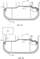
- FIGS 1A-1D show examples of an energy harvesting component in accordance with the invention. More specifically referring to Figure 1A , energy harvesting components 110 and 112 are disposed on a rotatable component 120 as shown. It is appreciated that the rotatable component 120 is a component configured to rotate for motion (e.g., to move or transport an object such as a vehicle, a train cart, etc.). For example, the rotatable component 120 may be a rim of a vehicle where rotation of the rim rotates a wheel causing the vehicle to move forward.
- the energy harvesting components 110 and 112 may be positioned on a side wall of the rotatable component 120. According to the invention, the energy harvesting components 110 and 112 are positioned between a bead area of a tire and the rotatable component 120 (e.g., the rim). It is appreciated that the energy harvesting components 110 and 112 may be positioned around a circumference of the rotatable component 120.
- the energy harvesting components 110 and 112 generate energy resulting from compressive force of the moving object (e.g., vehicle, acting on the bead area of the tire mounted on the rotatable component 120). In some embodiments, the compressive force may be due to loading (e.g., acceleration, deceleration, etc.).
- the location of the compressive force may vary depending on the loading.
- the energy harvesting components 110 and 112 capture a kinetic energy of the transport moving in response to the rotatable component 120 rotating.
- the energy harvesting components 110 and 112 may be a transducer, a piezo energy harvester, etc.
- the energy harvesting components 110 and 112 may generate electric potential when mechanical stress is applied to the energy harvesting components 110 and 112. It is appreciated that the energy harvesting component 110 may be the same as the energy harvesting component 112 or it may be different.
- a flexible component 130 is mounted on the rotatable component 120.
- the flexible component 130 is a tire (e.g., pneumatic tire, tube, etc.).
- the energy harvesting components 110 and 112 are positioned between a bead area of the flexible component 130 (e.g., a tire, tube, belt, etc.) and the rotatable component 120 (e.g., a rim, wheel, shaft, etc.).
- the harvesting components 110 and 112 generate energy resulting from compressive force of the transport acting on the bead area of the flexible component 130 (e.g., tire, tube, etc.). Further examples of energy harvesting component positioning are provided below.
- Figure 1C shows a sensor 140 powered by the energy harvesting component 112 through a connector 113.
- the connector 113 may be a wire.
- the sensor 140 may sense and collect sensing information.
- the sensing information may be pressure, speed at a moment of impact, acceleration (e.g., linear and/or angular), traction, braking steering, load support, temperature, force (static and/or dynamic), time of flight measurements, etc.
- the sensor 140 may be a pressure sensor, a micro-electro-mechanical systems (MEMS) based sensor, a gyro, etc.
- MEMS micro-electro-mechanical systems
- the rotatable component 120 e.g., a rim, wheel, shaft, etc.
- the lower part of the flexible component 130 e.g., a tire, tube, etc.
- internal pressure e.g., air pressure
- the bending causes vertical force to be applied to the bead area countering the weight of the moving object (e.g., a vehicle, a transport, a train cart, etc.).
- the energy harvesting components 110 and/or 112 positioned between the bead area and the rotatable component 120 generate high energy output due to the thickness mode of deformation on the energy harvesting components 110 and/or 112 and the compressive forces due to the weight of the moving object (e.g., a vehicle, a transport, a train cart, etc.).
- Figure 1D shows a tire pressure monitoring system (TPMS) module 150 powered by the energy harvesting component 110 through a connector 111.
- the connector 111 may be a wire
- the energy harvesting component 110 captures the kinetic energy. associated with the compressive force acting on the flexible component 130 (e.g., a tire, tube, etc.) as the rotatable component 120 (e.g., rim) rotates, and makes contact with a solid surface (e.g., a road).
- the TPMS module 150 is powered by the energy harvesting component 110 through the connector 111 (e.g., a circumferential interconnect ribbon).
- the flexible component 130 is coupled to the rotatable component 120 (e.g., a rim) and configured to transfer force to the rotatable component 120 resulting from compressive force of the moving device (e.g., a transport, a vehicle, etc.) acting on a portion of the flexible component making contact with a surface (e.g., a road).
- the energy harvesting components 110 and 112 may be positioned on a circumference of the rotatable component 120 and configured to capture a kinetic energy of the apparatus moving in response to the compressive force of the apparatus acting on the portion of the flexible component making contact with the surface as the rotatable component 120 rotates.
- a processing component e.g., a microcontroller, a processor, etc. may be coupled to the sensor(s) being powered by the energy harvesting component(s).
- the processing component may be a telemetry component, as an example.
- the processor may process the sensing information collected for various purposes (e.g., self-driving vehicle).
- FIG 2 shows an example of energy harvesting components and their positional configuration.
- the energy harvesting components 210 and 212 may be similar to those, as described in Figures 1A-1D .
- the energy harvesting components 210 and 212 may be positioned on a top horizontal portion of the rotatable component 120 instead of the sidewalls.
- the energy harvesting components may be positioned on both the sidewall as well as the top horizontal part of the rotatable component 120.
- a flexible component 130, a sensor 140, a TPMS module 150, connectors 111 and 113 or a combination thereof, as described in Figures 1A-1D may be used with the configuration of Figure 2 in similar fashion.
- FIG 3 shows another example of energy harvesting components and their positional configuration in accordance with some embodiments.
- the energy harvesting components 310 and 312 may be similar to those, as described in Figures 1A-1D .
- the energy harvesting components 310 and 312 may be positioned substantially on the entire sidewalls of the rotatable component 120.
- a flexible component 130, a sensor 140, a TPMS module 150, connectors 111 and 113 or a combination thereof, as described in Figures 1A-1D may be used with the configuration of Figure 3 in similar fashion.
- FIG 4 shows yet another example of energy harvesting components and their positional configuration in accordance with some embodiments.
- the energy harvesting components 410 and 412 may be similar to those, as described in Figures 1A-1D .
- the energy harvesting components 410 and 412 may be positioned substantially on the entire top horizontal portion of the rotatable component 120 and partially cover the sidewalls of the rotatable component 120.
- the energy harvesting components 410 and 412 may extend to the exterior vertical walls of the rotatable component 120 opposite to the interior sidewalls.
- a flexible component 130, a sensor 140, a TPMS module 150, connectors 111 and 113 or a combination thereof, as described in Figures 1A-1D may be used with the configuration of Figure 4 in similar fashion.
- FIG. 5 shows an additional example of energy harvesting component and its positional configuration in accordance with some embodiments.
- the energy harvesting components 510-516 may be similar to those, as described in Figures 1A-1D .
- the energy harvesting components 510 and 514 may be positioned on the top horizontal part of the rotatable component 120 while the energy harvesting components 512 and 516 are positioned on the interior sidewalls of the rotatable component 120.
- a flexible component 130, a sensor 140, a TPMS module 150, connectors 111 and 113 or a combination thereof, as described in Figures 1A-1D may be used with the configuration of Figure 5 in similar fashion.
- Figure 6 shows an example of an array of energy harvesting components in accordance with some embodiments. More specifically, Figure 6 depicts a side view of the rotatable component 120 and an array of energy harvesting components 610.
- the array of energy harvesting components 610 is a set of energy harvesting components, as described in Figures 1A-1D , 2, 3, 4, and 5 . As illustrated, the array of energy harvesting components 610 may be positioned around a circumference of the rotatable component 120, e.g., a rim. In some embodiments, the array may be positioned on the interior wall, on the top horizontal portion, on the exterior vertical wall, or any combination thereof of the rotatable component 120. In certain embodiments, the array of energy harvesting components 610 may be of a continuous single piece or material. In other embodiments, the array of energy harvesting components 610 may be of multiple discrete pieces or materials connected together.
- the array of energy harvesting components 610 generate substantially continuous energy as the rotatable component 120 (e.g., a rim) rotates.
- the array of energy harvesting components 610 capture a continuous kinetic energy of the moving object (e.g., a vehicle) in response to the compressive force of the moving object acting on the portion of the flexible component 130 (e.g., a tire) making contact with a surface (e.g., a road) as the rotatable component 120 (e.g., a rim) rotates.
- the substantially continuous energy is independent from resonance or off resonance conditions.
- the energy output is generated due to compression forces as the rotatable component 120 is rotating and is therefore not subjected to resonance or off-resonance conditions.
- the energy output may be resonance free in certain embodiments.
- the need to replace the energy harvesting components is eliminated each time the flexible component 130 (e.g., a tire) may be replaced since the energy harvesting components are mounted on the rotatable component 120 (e.g., a rim) thereby lowering the maintenance cost.
- the energy harvesting components may be coupled to an energy storage device (e.g., a battery) in order to provide recharge cycles, for continuous operating power even during stationary events.
- Figure 7 shows another example of an array of energy harvesting components in accordance with some embodiments.
- the arrangement for the embodiment shown in Figure 7 is substantially similar to that of Figure 6 except that the array of energy harvesting components 710 and 712 are separated by two gaps in some embodiments.
- Figure 8 shows further example of an array of energy harvesting components in accordance with some embodiments.
- the arrangement for the embodiment shown in Figure 8 is substantially similar to that of Figure 6 except that the array of energy harvesting components 810 includes twelve (12) separate energy harvesting components that are separated by gaps in between.
- Figure 9 shows yet another example of an array of energy harvesting components in accordance with some embodiments.
- Figure 9 is substantially similar to that of Figure 8 except that two different types of energy harvesting components (e.g., energy harvesting components 910 and 912) are used.
- energy harvesting components 910 and 912 two different types of energy harvesting components
- one set of energy harvesting components 910 may be transducers while the other set of energy harvesting components 912 may be piezo energy harvesters.
- FIG 10 shows an example of an energy harvesting component in the context of a vehicular wheel.
- the energy harvesting component 1002 may be appended to or positioned on the rotatable component 120 as described above.
- the energy harvesting component 1002 is illustrated in a particular orientation relative to the rotatable component 120, the energy harvesting component 1002 may be located in other orientations as desired for different applications
- the energy harvesting component 1002 may encircle a circumference of the rotatable component 120 or may otherwise cover a greater or smaller area of the rotatable component 120 than illustrated in Figure 10 .
- Spokes 1004 as part of the rotatable component 120 of the vehicular wheel 1000, are illustrated in phantom for reference.
- the energy harvesting component 1002 may also be proximate to or may directly contact the flexible component 130.
- the flexible component 130 may be, for example, a tire made of a flexible material.
- the flexible component 130 may incur mechanical stress while, for example, the rotatable component 120 rotates or is otherwise in motion. This mechanical stress may be due to, for example, a compressive force of an object moved using the flexible component 130 (e.g., vehicle, acting on the bead area of the tire mounted on the rotatable component 120).
- Such mechanical stress incurred by the flexible component 130 may be imparted to the energy harvesting component 1002 proximate to or contacting the flexible component 130.
- the energy harvesting component 1002 may harvest power or energy (e.g., as electric potential) based on the mechanical stress applied to the energy harvesting component 1002.
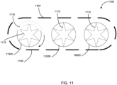
- FIG 11 shows an example of an energy harvesting component in the context of a belt system.
- the belt system 1100 may have multiple rotatable components 1102A-1102C which may move a flexible component 1104 around the rotatable components 1102A-1102C.
- the flexible component 1104 is illustrated as a dashed line and may be, for example, a conveyor belt or a track. Accordingly, the flexible component 1104 may be used to, for example, move objects placed on a surface of the flexible component 1104 or move an object connected with the rotatable components 1102A-1102C for locomotion.
- An energy harvesting component 1110 may be appended to or positioned on at least one of the rotatable components 1102A-1102C as described above. As illustrated, the energy harvesting component 1110 is appended to or positioned on the rotatable component 1102A. Although the energy harvesting component 1110 is illustrated in a particular orientation relative to the rotatable component 1102A, the energy harvesting component may be located in other orientations as desired for different applications. For example, as discussed above, the energy harvesting component 1110 may encircle a circumference of the rotatable component 1102A or may otherwise cover a greater or smaller area of the rotatable component 1102A than illustrated in Figure 11 . Spokes 1112, as part of each rotatable component 1102A-1102C, are illustrated in phantom for reference.
- the flexible component 1104 is illustrated with space from the rotatable components 1102A-1102C and/or the energy harvesting component 1110. However, the flexible component 1104 may be proximate to or may directly contact the energy harvesting component 1110 and/or the rotatable components 1102A-1102C. As noted above, the flexible component 1104 may be, for example, a conveyor belt or a track. The flexible component 1104 may incur mechanical stress while, for example, the rotatable component 1102A or flexible component 1102 is in motion.
- This mechanical stress may be due to, for example, a compressive force of an object moved using the flexible component 1104 (e.g., a vehicle moved while using the flexible component 1104 as a track or an object moved while using the flexible component 1104 as a conveyor belt).
- Such mechanical stress incurred by the flexible component 1104 may be imparted to the energy harvesting component 1110 proximate to or contacting the flexible component 1104.
- the energy harvesting component 1110 may harvest power or energy (e.g., as electric potential) based on the mechanical stress applied to the energy harvesting component 1110.
- FIG 12 shows an example of an energy harvesting component in the context of a master-slave belt system.
- the master-slave belt system 1200 may have multiple rotatable components 1202A and 1202B, which may move a flexible component 1204 around the rotatable components 1202A and 1202B.
- the flexible component 1204 is illustrated as a dashed line and may be, for example, a belt that connects the rotatable components 1202A and 1202B in a master-slave relationship.
- the rotatable component 1202A may rotate and cause the rotatable component 1202B to rotate, as a slave rotatable component, using the flexible component 1204.
- the rotatable component 1202A may be connected with blades 1206 that rotate the rotatable component 1202A as part of, for example, a windmill, a water mill, or other rotatable apparatus that may rotate via application of force upon at least one of the blades 1206.
- the rotatable component 1202B may rotate and cause the rotatable component 1202A to rotate, as a slave rotatable component, using the flexible component 1204.
- the rotatable component 1202B may be connected with a motor that rotates the rotatable component 1202B.
- the rotation of the rotatable component 1202B may be imparted to the rotatable component 1202A via the flexible component 1204.
- the rotatable component 1202A may rotate with structures connected to the rotatable component 1202A. These structures may be, for example, blades 1206 of a propeller or other apparatus structured to rotate by application of rotational force upon the rotatable component 1202A.
- An energy harvesting component 1210 may be appended to or positioned on at least one of the rotatable components 1202A or 1202B as described above. As illustrated, the energy harvesting component 1210 is appended to or positioned on the rotatable component 1202A. Although the energy harvesting component 1210 is illustrated in a particular orientation relative to the rotatable component 1202A, the energy harvesting component may be located in other orientations as desired for different applications. For example, as discussed above, the energy harvesting component 1210 may encircle a circumference of the rotatable component 1202A or may otherwise cover a greater or smaller area of the rotatable component 1202A than illustrated in Figure 12 .
- the flexible component 1204 is illustrated with space from the rotatable components 1202A, 1202B, and/or the energy harvesting component 1210. However, the flexible component 1204 may be proximate to or may directly contact the energy harvesting component 1210 and/or the rotatable components 1202A and 1202B. As noted above, the flexible component 1204 may be, for example, a belt that connects the rotatable components 1202A and 1202B in a master-slave relationship. The flexible component 1204 may incur mechanical stress while, for example, the rotatable component 1202A rotates or is otherwise in motion. This mechanical stress may be due to, for example, a compressive force due to loading (e.g., acceleration, deceleration, etc.).
- loading e.g., acceleration, deceleration, etc.
- the location of the compressive force may vary depending on the loading.
- Such mechanical stress incurred by the flexible component 1204 may be imparted to the energy harvesting component 1210 proximate to or contacting the flexible component 1204.
- mechanical stress may be imparted to the energy harvesting component 1210 due to loading (e.g., acceleration, deceleration, etc.) associated with rotation of the rotatable component.
- the energy harvesting component 1210 may harvest power or energy (e.g., as electric potential) based on the mechanical stress applied to the energy harvesting component 1210.
Landscapes
- Engineering & Computer Science (AREA)
- Mechanical Engineering (AREA)
- Physics & Mathematics (AREA)
- General Physics & Mathematics (AREA)
- General Electrical Machinery Utilizing Piezoelectricity, Electrostriction Or Magnetostriction (AREA)
- Handcart (AREA)
- Testing Of Balance (AREA)
- Arrangements For Transmission Of Measured Signals (AREA)
- Tires In General (AREA)
Description
- The invention refers to an apparatus comprising a rim, a tire and an energy harvesting component.
- Advancements in technology and data mining have become prevalent in everyday life. For example, data mining for the purposes of self-driving vehicles has become a daily occurrence. Similarly, data mining in other industries has also increased in order to improve products' usability as well as safety. For example, collecting data in a car accident and investigating it may lead to the cause of the accident (e.g., tire pressure, engine malfunction, etc.). As such, use of sensors in everyday life has become ubiquitous. Increase in use of sensors has led to an increase in power demand and data transmission. Unfortunately, current power sources such as lithium ion batteries are limited in their capacity and have low durability, in addition to difficulty in replacing them (e.g., when they supply power to sensors inside pneumatic tires for example). Furthermore, lithium ion batteries adversely impact the environment. Moreover, lithium ion batteries are subject to accelerated discharge cycles that require frequent or premature replacement of the entire sensor modules, thereby increasing the cost.
- Attempts have been made to harvest energy to address the increase in power demand. For example, technology has been introduced to harvest energy from a kinetic source (e.g., vibration, shock, etc.), a heat source, a light source, etc. Unfortunately, the current technology for harvesting energy and its efficiency is dependent on a varying speed of the wheel. Additionally, other means such as mass-spring-damper have a narrow frequency range and are poorly suited for harvesting energy by having a non-linear output under off-resonance conditions.
-
US 6,291,901 B1 discloses a method and device for generating electrical energy from the rotation of a wheel of a vehicle is disclosed. The device is disposed within a pneumatic tire and includes a coil housing having an interior chamber with a coil disposed thereabout, which is aligned for receiving a magnet within the chamber. The magnet is mounted within a magnet housing which has a first end aligned for reception in the groove of the coil housing, and a second end in communication with the interior wall of a tire. As the tire rotates, the tire deflection causes relative motion between the magnet and the coil generating electricity. -
US 3,699,367 A discloses a device, located within a flexible vehicle tire, which has one portion corotatable with the wheel and a second portion which is reciprocated in a radial sense by the normal flexure of the tire, as the tire moves into ground engagement, is first depressed and then expands to its original condition after moving out of ground engagement. The relative radial movement which occurs between these two portions is utilized to operate an electromagnetic generator. -
WO 2014/011129 A1 discloses a continuous power generator for wheeled vehicles, wherein power generation in wheeled vehicles is provided using inert the inner hole of the wheel thanks to pushing/deformation force created by a force at the point where the rotating wheel of the moving vehicle contacts with the ground, said force being applied on the wheel, said force pushing the drive shafts located inside the wheel at the time when ground contact points touch, and said force moving an alternator or a magnet coil generator. -
WO 2008/036088 A1 , corresponding toEP 2 040 942 A0 , discloses an apparatus and methodology for monitoring tire related conditions. A substrate is provided having one or more pairs of sensors mounted thereon. The pairs of sensors are mounted in predetermined relationship to each other at predetermined separation distances such that rotational direction, speed and other parameters of a tire with which the sensors may be associated may be determined. In some embodiments, plural effective pairs of sensors are provided so that mounting orientation of the sensor need not be predetermined. -
US 2006/022555 A1 discloses an energy harvesting device, system and method. The energy harvester collects acoustic energy and transforms it into electrical energy for use by a sensor. The energy harvester utilizes a piezoelectric device, which may be encased, either wholly or partially, within an acoustic chamber. Alternatively, the piezoelectric device may be entirely exterior to the acoustic chamber, which acts to amplify the collected acoustic energy. - Accordingly, there is a need to harvest energy efficiently and independent of varying speed of a moving object such as a vehicle. According to the invention, an energy harvesting component is positioned on a rotatable component such that it captures the kinetic energy of the rotatable component independent of the speed of the rotatable component.
- According to the invention, an apparatus includes a rim, a tire, and an energy harvesting component. The rim is configured to rotate and move. The tire is coupled to the rim. The tire when inflated is configured to transfer force to the rim resulting from compressive force acting on a portion of the tire making contact with a road. The energy harvesting component is positioned on the rim and configured to capture a kinetic energy in response to the compressive force acting on the portion of the tire making contact with the road as the rim rotates.
- It is appreciated that in one example according to some embodiments, the energy harvesting component is positioned on a side wall of the rim. According to the invention, the energy harvesting component is positioned between a bead area of the tire and the rim. The energy harvesting component generates energy resulting from compressive force acting on the bead area of the tire. According to one example, the energy harvesting component is a transducer, a piezo energy harvester, etc.
- In some embodiments, the energy harvesting component may be an array of energy harvesting components positioned around a circumference of the rim. The array of energy harvesting components generate substantially continuous energy as the rim rotates. It is appreciated that the substantially continuous energy is independent from resonance or off resonance conditions.
- According to some embodiments, the apparatus further includes a tire pressure monitoring system (TPMS) module configured to receive the captured kinetic energy. The kinetic energy is transferred to the TPMS module via circumferential interconnect ribbon with electrodes for carrying electric current. In some embodiments, the apparatus may further include a sensor that is powered by the captured kinetic energy.
- In some embodiments, a device includes a rotatable component configured to rotate and move a transport in response thereto. The apparatus may further include an energy harvesting component positioned on the rotatable component. The energy harvesting component is configured to capture a kinetic energy of the transport moving in response to the rotatable component rotating.
- In some embodiments, the energy harvesting component is a transducer, a piezo energy harvester, etc. The device may further include a tire coupled to the rotatable component. The energy harvesting component is positioned between a bead area of the tire and the rotatable component and generates energy resulting from compressive force of the transport acting on the bead area of the tire.
- It is appreciated that the energy harvesting component may be an array of energy harvesting components positioned around a circumference of the rotatable component. The array of energy harvesting components may generate substantially continuous energy as the rotatable component rotates.
- According to some embodiments, the device further includes a TPMS module configured to receive the captured kinetic energy. The kinetic energy is transferred to the TPMS module via circumferential interconnect ribbon with electrodes for carrying electric current. In one example according to some embodiments, the device further includes a sensor that is powered by the captured kinetic energy.
- In an example according to some embodiments, an apparatus includes a rim, a flexible component an array of energy harvesting components, and an array of sensors. The rim is configured to rotate and move the apparatus in response thereto. The flexible component is coupled to the rim and configured to transfer force to the rim resulting from compressive force of the apparatus acting on a portion of the flexible component making contact with a surface. The array of energy harvesting components is positioned on a circumference of the rim and configured to capture a continuous kinetic energy of the apparatus moving in response to the compressive force of the apparatus acting on the portion of the flexible component making contact with the surface as the rim rotates. It is appreciated that the captured continuous kinetic energy is independent from resonance or off resonance conditions. The array of sensors is powered by the array of energy harvesting components.
- In some embodiments, the array of sensors is configured to sense and collect apparatus sensing information. The apparatus sensing information may be pressure, speed at a moment of impact, acceleration, traction, braking steering, load support, etc.
- These and other features and aspects of the concepts described herein may be better understood with reference to the following drawings, description, and appended claims.
-
-
Figure 1A shows an example of an energy harvesting component in accordance with the invention. -
Figure 1B shows another example of an energy harvesting component in accordance with the invention. -
Figure 1C shows yet another example of an energy harvesting component in accordance with some embodiments. -
Figure 1D shows a further example of an energy harvesting component in accordance with some embodiments. -
Figure 2 shows an example of an energy harvesting component and its positional configuration in accordance with some embodiments. -
Figure 3 shows another example of an energy harvesting component and its positional configuration in accordance with some embodiments. -
Figure 4 shows yet another example of an energy harvesting component and its positional configuration in accordance with some embodiments. -
Figure 5 shows an additional example of an energy harvesting component and its positional configuration in accordance with some embodiments. -
Figure 6 shows an example of an array of energy harvesting components in accordance with some embodiments. -
Figure 7 shows another example of an array of energy harvesting components in accordance with some embodiments. -
Figure 8 shows a further example of an array of energy harvesting components in accordance with some embodiments. -
Figure 9 shows yet another example of an array of energy harvesting components in accordance with some embodiments. -
Figure 10 shows an example of an energy harvesting component in the context of a vehicular wheel. -
Figure 11 shows an example of an energy harvesting component in the context of a belt system. -
Figure 12 shows an example of an energy harvesting component in the context of a master-slave belt system. - Before various embodiments are described in greater detail, it should be understood by persons having ordinary skill in the art that the embodiments are not limiting, as elements in such embodiments may vary. It should likewise be understood that a particular embodiment described and/or illustrated herein has elements which may be readily separated from the particular embodiment and optionally combined with any of several other embodiments or substituted for elements in any of several other embodiments described herein.
- It should also be understood by persons having ordinary skill in the art that the terminology used herein is for the purpose of describing the certain concepts, and the terminology is not intended to be limiting. Unless indicated otherwise, ordinal numbers (e.g., first, second, third, etc.) are used to distinguish or identify different elements or steps in a group of elements or steps, and do not supply a serial or numerical limitation on the elements or steps of the embodiments thereof. For example, "first," "second," and "third" elements or steps need not necessarily appear in that order, and the embodiments thereof need not necessarily be limited to three elements or steps. It should also be understood that, unless indicated otherwise, any labels such as "left," "right," "front," "back," "top," "middle," "bottom," "forward," "reverse," "clockwise," "counter clockwise," "up," "down," or other similar terms such as "upper," "lower," "above," "below," "vertical," "horizontal," "proximal," "distal," and the like are used for convenience and are not intended to imply, for example, any particular fixed location, orientation, or direction. Instead, such labels are used to reflect, for example, relative location, orientation, or directions. It should also be understood that the singular forms of "a," "an," and "the" include plural references unless the context clearly dictates otherwise.
- Unless defined otherwise, all technical and scientific terms used herein have the same meaning as commonly understood by persons of ordinary skill in the art to which the embodiments pertain.
- There is a need to harvest energy efficiently and independently of the varying speed of a moving object, such as a vehicle. In some embodiments, an energy harvesting component is positioned on a rotatable component, such that it captures the kinetic energy of the rotatable component independently of the speed of the rotatable component.
-
Figures 1A-1D show examples of an energy harvesting component in accordance with the invention. More specifically referring toFigure 1A ,energy harvesting components rotatable component 120 as shown. It is appreciated that therotatable component 120 is a component configured to rotate for motion (e.g., to move or transport an object such as a vehicle, a train cart, etc.). For example, therotatable component 120 may be a rim of a vehicle where rotation of the rim rotates a wheel causing the vehicle to move forward. - The
energy harvesting components rotatable component 120. According to the invention, theenergy harvesting components energy harvesting components rotatable component 120. Theenergy harvesting components energy harvesting components rotatable component 120 rotating. According to one example, theenergy harvesting components energy harvesting components energy harvesting components energy harvesting component 110 may be the same as theenergy harvesting component 112 or it may be different. - Referring now to
Figure 1B , aflexible component 130 is mounted on therotatable component 120. According to the invention, theflexible component 130 is a tire (e.g., pneumatic tire, tube, etc.). Theenergy harvesting components harvesting components -
Figure 1C shows asensor 140 powered by theenergy harvesting component 112 through aconnector 113. Theconnector 113 may be a wire. Thesensor 140 may sense and collect sensing information. The sensing information may be pressure, speed at a moment of impact, acceleration (e.g., linear and/or angular), traction, braking steering, load support, temperature, force (static and/or dynamic), time of flight measurements, etc. In some embodiments, thesensor 140 may be a pressure sensor, a micro-electro-mechanical systems (MEMS) based sensor, a gyro, etc. - It is appreciated that as the rotatable component 120 (e.g., a rim, wheel, shaft, etc.) rotates, the lower part of the flexible component 130 (e.g., a tire, tube, etc.) bends due to internal pressure (e.g., air pressure). The bending causes vertical force to be applied to the bead area countering the weight of the moving object (e.g., a vehicle, a transport, a train cart, etc.). Thus, the
energy harvesting components 110 and/or 112 positioned between the bead area and the rotatable component 120 (e.g., a rim) generate high energy output due to the thickness mode of deformation on theenergy harvesting components 110 and/or 112 and the compressive forces due to the weight of the moving object (e.g., a vehicle, a transport, a train cart, etc.). -
Figure 1D shows a tire pressure monitoring system (TPMS)module 150 powered by theenergy harvesting component 110 through aconnector 111. Theconnector 111 may be a wire Theenergy harvesting component 110 captures the kinetic energy. associated with the compressive force acting on the flexible component 130 (e.g., a tire, tube, etc.) as the rotatable component 120 (e.g., rim) rotates, and makes contact with a solid surface (e.g., a road). In some embodiments, theTPMS module 150 is powered by theenergy harvesting component 110 through the connector 111 (e.g., a circumferential interconnect ribbon). - According to the invention, the
flexible component 130 is coupled to the rotatable component 120 (e.g., a rim) and configured to transfer force to therotatable component 120 resulting from compressive force of the moving device (e.g., a transport, a vehicle, etc.) acting on a portion of the flexible component making contact with a surface (e.g., a road). Theenergy harvesting components rotatable component 120 and configured to capture a kinetic energy of the apparatus moving in response to the compressive force of the apparatus acting on the portion of the flexible component making contact with the surface as therotatable component 120 rotates. - It is appreciated that a processing component, e.g., a microcontroller, a processor, etc. may be coupled to the sensor(s) being powered by the energy harvesting component(s). The processing component may be a telemetry component, as an example. As such, the processor may process the sensing information collected for various purposes (e.g., self-driving vehicle).
- It is further appreciated that while the embodiments are described with respect to an object moving (e.g., rotating) such an apparatus may be equally applicable to any type of mechanical stress, such as vibration, oscillation back and forth, etc.
-
Figure 2 shows an example of energy harvesting components and their positional configuration. For example, theenergy harvesting components Figures 1A-1D . However, in this example theenergy harvesting components rotatable component 120 instead of the sidewalls. However, it is appreciated that the energy harvesting components may be positioned on both the sidewall as well as the top horizontal part of therotatable component 120. It is further appreciated that aflexible component 130, asensor 140, aTPMS module 150,connectors Figures 1A-1D , may be used with the configuration ofFigure 2 in similar fashion. -
Figure 3 shows another example of energy harvesting components and their positional configuration in accordance with some embodiments. For example, theenergy harvesting components Figures 1A-1D . However, in this example according to some embodiments theenergy harvesting components rotatable component 120. It is appreciated that aflexible component 130, asensor 140, aTPMS module 150,connectors Figures 1A-1D , may be used with the configuration ofFigure 3 in similar fashion. -
Figure 4 shows yet another example of energy harvesting components and their positional configuration in accordance with some embodiments. For example, theenergy harvesting components Figures 1A-1D . However, in this example according to some embodiments theenergy harvesting components rotatable component 120 and partially cover the sidewalls of therotatable component 120. In some examples, theenergy harvesting components rotatable component 120 opposite to the interior sidewalls. It is appreciated that aflexible component 130, asensor 140, aTPMS module 150,connectors Figures 1A-1D , may be used with the configuration ofFigure 4 in similar fashion. -
Figure 5 shows an additional example of energy harvesting component and its positional configuration in accordance with some embodiments. For example, the energy harvesting components 510-516 may be similar to those, as described inFigures 1A-1D . However, in this example according to some embodiments theenergy harvesting components rotatable component 120 while theenergy harvesting components rotatable component 120. It is appreciated that aflexible component 130, asensor 140, aTPMS module 150,connectors Figures 1A-1D , may be used with the configuration ofFigure 5 in similar fashion. - It is appreciated that the number energy harvesting components and/or sensors, etc. that are described and shown are for illustrative purposes only. As such, the number of energy harvesting components and/or the number sensors, etc. that are illustrated should not be construed as limiting the scope of the invention.
-
Figure 6 shows an example of an array of energy harvesting components in accordance with some embodiments. More specifically,Figure 6 depicts a side view of therotatable component 120 and an array ofenergy harvesting components 610. The array ofenergy harvesting components 610 is a set of energy harvesting components, as described inFigures 1A-1D ,2, 3, 4, and 5 . As illustrated, the array ofenergy harvesting components 610 may be positioned around a circumference of therotatable component 120, e.g., a rim. In some embodiments, the array may be positioned on the interior wall, on the top horizontal portion, on the exterior vertical wall, or any combination thereof of therotatable component 120. In certain embodiments, the array ofenergy harvesting components 610 may be of a continuous single piece or material. In other embodiments, the array ofenergy harvesting components 610 may be of multiple discrete pieces or materials connected together. - In some embodiments, the array of
energy harvesting components 610 generate substantially continuous energy as the rotatable component 120 (e.g., a rim) rotates. In other words, the array ofenergy harvesting components 610 capture a continuous kinetic energy of the moving object (e.g., a vehicle) in response to the compressive force of the moving object acting on the portion of the flexible component 130 (e.g., a tire) making contact with a surface (e.g., a road) as the rotatable component 120 (e.g., a rim) rotates. It is appreciated that the substantially continuous energy is independent from resonance or off resonance conditions. In other words, the energy output is generated due to compression forces as therotatable component 120 is rotating and is therefore not subjected to resonance or off-resonance conditions. Stated differently again, the energy output may be resonance free in certain embodiments. Moreover, the need to replace the energy harvesting components is eliminated each time the flexible component 130 (e.g., a tire) may be replaced since the energy harvesting components are mounted on the rotatable component 120 (e.g., a rim) thereby lowering the maintenance cost. It is also appreciated that the energy harvesting components may be coupled to an energy storage device (e.g., a battery) in order to provide recharge cycles, for continuous operating power even during stationary events. -
Figure 7 shows another example of an array of energy harvesting components in accordance with some embodiments. The arrangement for the embodiment shown inFigure 7 is substantially similar to that ofFigure 6 except that the array ofenergy harvesting components -
Figure 8 shows further example of an array of energy harvesting components in accordance with some embodiments. The arrangement for the embodiment shown inFigure 8 is substantially similar to that ofFigure 6 except that the array ofenergy harvesting components 810 includes twelve (12) separate energy harvesting components that are separated by gaps in between. -
Figure 9 shows yet another example of an array of energy harvesting components in accordance with some embodiments.Figure 9 is substantially similar to that ofFigure 8 except that two different types of energy harvesting components (e.g.,energy harvesting components 910 and 912) are used. For example, one set ofenergy harvesting components 910 may be transducers while the other set ofenergy harvesting components 912 may be piezo energy harvesters. -
Figure 10 shows an example of an energy harvesting component in the context of a vehicular wheel. As part of thevehicular wheel 1000, theenergy harvesting component 1002 may be appended to or positioned on therotatable component 120 as described above. Although theenergy harvesting component 1002 is illustrated in a particular orientation relative to therotatable component 120, theenergy harvesting component 1002 may be located in other orientations as desired for different applications For example, as discussed above, theenergy harvesting component 1002 may encircle a circumference of therotatable component 120 or may otherwise cover a greater or smaller area of therotatable component 120 than illustrated inFigure 10 .Spokes 1004, as part of therotatable component 120 of thevehicular wheel 1000, are illustrated in phantom for reference. - The
energy harvesting component 1002 may also be proximate to or may directly contact theflexible component 130. As noted above, theflexible component 130 may be, for example, a tire made of a flexible material. Theflexible component 130 may incur mechanical stress while, for example, therotatable component 120 rotates or is otherwise in motion. This mechanical stress may be due to, for example, a compressive force of an object moved using the flexible component 130 (e.g., vehicle, acting on the bead area of the tire mounted on the rotatable component 120). Such mechanical stress incurred by theflexible component 130 may be imparted to theenergy harvesting component 1002 proximate to or contacting theflexible component 130. As noted above, theenergy harvesting component 1002 may harvest power or energy (e.g., as electric potential) based on the mechanical stress applied to theenergy harvesting component 1002. -
Figure 11 shows an example of an energy harvesting component in the context of a belt system. Thebelt system 1100 may have multiplerotatable components 1102A-1102C which may move aflexible component 1104 around therotatable components 1102A-1102C. Theflexible component 1104 is illustrated as a dashed line and may be, for example, a conveyor belt or a track. Accordingly, theflexible component 1104 may be used to, for example, move objects placed on a surface of theflexible component 1104 or move an object connected with therotatable components 1102A-1102C for locomotion. - An
energy harvesting component 1110 may be appended to or positioned on at least one of therotatable components 1102A-1102C as described above. As illustrated, theenergy harvesting component 1110 is appended to or positioned on therotatable component 1102A. Although theenergy harvesting component 1110 is illustrated in a particular orientation relative to therotatable component 1102A, the energy harvesting component may be located in other orientations as desired for different applications. For example, as discussed above, theenergy harvesting component 1110 may encircle a circumference of therotatable component 1102A or may otherwise cover a greater or smaller area of therotatable component 1102A than illustrated inFigure 11 .Spokes 1112, as part of eachrotatable component 1102A-1102C, are illustrated in phantom for reference. - For ease of illustration, the
flexible component 1104 is illustrated with space from therotatable components 1102A-1102C and/or theenergy harvesting component 1110. However, theflexible component 1104 may be proximate to or may directly contact theenergy harvesting component 1110 and/or therotatable components 1102A-1102C. As noted above, theflexible component 1104 may be, for example, a conveyor belt or a track. Theflexible component 1104 may incur mechanical stress while, for example, therotatable component 1102A or flexible component 1102 is in motion. This mechanical stress may be due to, for example, a compressive force of an object moved using the flexible component 1104 (e.g., a vehicle moved while using theflexible component 1104 as a track or an object moved while using theflexible component 1104 as a conveyor belt). Such mechanical stress incurred by theflexible component 1104 may be imparted to theenergy harvesting component 1110 proximate to or contacting theflexible component 1104. As noted above, theenergy harvesting component 1110 may harvest power or energy (e.g., as electric potential) based on the mechanical stress applied to theenergy harvesting component 1110. -
Figure 12 shows an example of an energy harvesting component in the context of a master-slave belt system. The master-slave belt system 1200 may have multiplerotatable components flexible component 1204 around therotatable components flexible component 1204 is illustrated as a dashed line and may be, for example, a belt that connects therotatable components - The
rotatable component 1202A, as a master rotatable component, may rotate and cause therotatable component 1202B to rotate, as a slave rotatable component, using theflexible component 1204. For example, therotatable component 1202A may be connected withblades 1206 that rotate therotatable component 1202A as part of, for example, a windmill, a water mill, or other rotatable apparatus that may rotate via application of force upon at least one of theblades 1206. - In another apparatus, the
rotatable component 1202B, as a master rotatable component, may rotate and cause therotatable component 1202A to rotate, as a slave rotatable component, using theflexible component 1204. For example, therotatable component 1202B may be connected with a motor that rotates therotatable component 1202B. The rotation of therotatable component 1202B may be imparted to therotatable component 1202A via theflexible component 1204. Then, therotatable component 1202A may rotate with structures connected to therotatable component 1202A. These structures may be, for example,blades 1206 of a propeller or other apparatus structured to rotate by application of rotational force upon therotatable component 1202A. - An
energy harvesting component 1210 may be appended to or positioned on at least one of therotatable components energy harvesting component 1210 is appended to or positioned on therotatable component 1202A. Although theenergy harvesting component 1210 is illustrated in a particular orientation relative to therotatable component 1202A, the energy harvesting component may be located in other orientations as desired for different applications. For example, as discussed above, theenergy harvesting component 1210 may encircle a circumference of therotatable component 1202A or may otherwise cover a greater or smaller area of therotatable component 1202A than illustrated inFigure 12 . - For ease of illustration, the
flexible component 1204 is illustrated with space from therotatable components energy harvesting component 1210. However, theflexible component 1204 may be proximate to or may directly contact theenergy harvesting component 1210 and/or therotatable components flexible component 1204 may be, for example, a belt that connects therotatable components flexible component 1204 may incur mechanical stress while, for example, therotatable component 1202A rotates or is otherwise in motion. This mechanical stress may be due to, for example, a compressive force due to loading (e.g., acceleration, deceleration, etc.). The location of the compressive force may vary depending on the loading. Such mechanical stress incurred by theflexible component 1204 may be imparted to theenergy harvesting component 1210 proximate to or contacting theflexible component 1204. Stated another way, mechanical stress may be imparted to theenergy harvesting component 1210 due to loading (e.g., acceleration, deceleration, etc.) associated with rotation of the rotatable component. As noted above, theenergy harvesting component 1210 may harvest power or energy (e.g., as electric potential) based on the mechanical stress applied to theenergy harvesting component 1210. - While the embodiments have been described and/or illustrated by means of particular examples, and while these embodiments and/or examples have been described in considerable detail, it is not the intention of the Applicants to restrict or in any way limit the scope of the invention to such detail.
Claims (12)
- An apparatus comprising:a rim (120) configured to rotate and move;a tire (130) coupled to the rim (120), wherein the tire (130) when inflated is configured to transfer force to the rim (120) resulting from compressive force acting on a portion of the tire (130) making contact with a road; andan energy harvesting component (110; 112) positioned on the rim (120), wherein the energy harvesting component (110; 112) is configured to capture a kinetic energy in response to the compressive force acting on the portion of the tire (130) making contact with the road as the rim (120) rotates,characterized in that the energy harvesting component (110; 112) is positioned between a bead area of the tire (130) and the rim (120), and wherein the energy harvesting component (110; 112) generates energy resulting from the compressive force acting on the bead area of the tire (130).
- The apparatus of claim 1, wherein the energy harvesting component (110; 112) is a transducer.
- The apparatus of claim 2, wherein the transducer is a piezo energy harvester.
- The apparatus of any preceding claim, wherein the energy harvesting component (110; 112) is an array of energy harvesting components (610) positioned around a circumference of the rim, and wherein the array of energy harvesting components (110; 112) generate substantially continuous energy as the rim rotates, and wherein the substantially continuous energy is independent from resonance or off resonance conditions.
- The apparatus of any preceding claim further comprising a sensor (140), wherein the sensor (140) is powered by the captured kinetic energy.
- The apparatus of claim 5, wherein the sensor (140) is within a tire pressure monitoring system, TPMS, module (150) configured to receive the captured kinetic energy.
- The apparatus of claim 6, wherein the kinetic energy is transferred to the TPMS module (150) via circumferential interconnect ribbon with electrodes for carrying electric current.
- The apparatus of any preceding claim, wherein the energy harvesting component (110; 112) is an array of energy harvesting components (610) positioned around a circumference of the rim, and wherein the array of energy harvesting components (610) generate substantially continuous energy as the rim rotates.
- The apparatus of any preceding claim, wherein the rim is coupled with at least one blade (1206) that rotates the rotatable component in response to force applied to the at least one blade (1206).
- The apparatus of any of claims 8 and 9 further comprising an array of sensors powered by the array of energy harvesting components.
- The apparatus of claim 10, wherein the array of sensors is configured to sense and collect apparatus sensing information.
- The apparatus of claim 11, wherein the apparatus sensing information is selected from a group consisting of pressure, speed at a moment of impact, acceleration, traction, braking steering, and load support.
Applications Claiming Priority (1)
| Application Number | Priority Date | Filing Date | Title |
|---|---|---|---|
| US16/158,216 US11325432B2 (en) | 2018-10-11 | 2018-10-11 | Rotating wheel and an energy harvesting system |
Publications (3)
| Publication Number | Publication Date |
|---|---|
| EP3636462A1 EP3636462A1 (en) | 2020-04-15 |
| EP3636462A8 EP3636462A8 (en) | 2020-06-10 |
| EP3636462B1 true EP3636462B1 (en) | 2024-08-14 |
Family
ID=68609858
Family Applications (1)
| Application Number | Title | Priority Date | Filing Date |
|---|---|---|---|
| EP19202300.0A Active EP3636462B1 (en) | 2018-10-11 | 2019-10-09 | Rotating wheel and an energy harvesting system |
Country Status (3)
| Country | Link |
|---|---|
| US (1) | US11325432B2 (en) |
| EP (1) | EP3636462B1 (en) |
| CN (1) | CN111038184B (en) |
Families Citing this family (4)
| Publication number | Priority date | Publication date | Assignee | Title |
|---|---|---|---|---|
| US11560022B2 (en) * | 2018-12-12 | 2023-01-24 | Tdk Corporation | Rotatable smart wheel systems and methods |
| US11865872B2 (en) * | 2020-11-02 | 2024-01-09 | Tdk Corporation | Interconnects for electrical components positioned adjacent to vehicle tires |
| US12552388B2 (en) * | 2021-09-22 | 2026-02-17 | Tdk Corporation | Devices and methods of detecting driving conditions from a rotating wheel |
| JP7805139B2 (en) * | 2021-11-18 | 2026-01-23 | Tdk株式会社 | Estimation system, estimation method, and estimation program |
Citations (4)
| Publication number | Priority date | Publication date | Assignee | Title |
|---|---|---|---|---|
| US3699367A (en) * | 1971-08-13 | 1972-10-17 | Stephen E Thomas | Mechanism for obtaining energy from tire flexure |
| US6291901B1 (en) * | 2000-06-13 | 2001-09-18 | ćEFO NEVRES | Electrical power generating tire system |
| US20060022555A1 (en) * | 2004-08-02 | 2006-02-02 | General Electric Company | Energy harvesting system, apparatus and method |
| WO2014011129A1 (en) * | 2012-07-12 | 2014-01-16 | Bayrakdar Hami | Continuous power generator for wheeled vehicles |
Family Cites Families (22)
| Publication number | Priority date | Publication date | Assignee | Title |
|---|---|---|---|---|
| CA1145829A (en) * | 1979-04-30 | 1983-05-03 | Robert C. Green | Digitally encoded abnormal tire condition indicating system |
| US4554527A (en) * | 1980-03-27 | 1985-11-19 | Ford Motor Company | Tire height sensor with valve stem attaching transmitter module |
| US4504761A (en) * | 1981-12-28 | 1985-03-12 | Triplett Charles G | Vehicular mounted piezoelectric generator |
| AU6085100A (en) | 1999-07-12 | 2001-01-30 | Geomat Insights, Llc | Wireless remote tire parameter measurement method and apparatus |
| ES2231478T3 (en) | 2000-03-16 | 2005-05-16 | Pirelli Pneumatici S.P.A. | SYSTEM, TIRE AND METHOD TO DETERMINE THE BEHAVIOR OF A MOVING TIRE. |
| US7161476B2 (en) | 2000-07-26 | 2007-01-09 | Bridgestone Firestone North American Tire, Llc | Electronic tire management system |
| US6725713B2 (en) * | 2002-05-10 | 2004-04-27 | Michelin & Recherche Et Technique S.A. | System for generating electric power from a rotating tire's mechanical energy using reinforced piezoelectric materials |
| ES2314074T3 (en) | 2002-06-28 | 2009-03-16 | Pirelli Tyre S.P.A. | SYSTEM FOR MONOTORIZING THE CHARACTERISTIC PARAMETERS OF A PNEUMATIC. |
| KR100555659B1 (en) | 2003-12-22 | 2006-03-03 | 삼성전자주식회사 | Self-generated sensing module and tire pressure monitoring system using it |
| CA2552092A1 (en) * | 2003-12-29 | 2005-07-21 | Pirelli Pneumatici S.P.A. | Method and system for generating electrical energy within a vehicle tyre |
| US20080061625A1 (en) | 2006-09-07 | 2008-03-13 | Ford Global Technologies, Llc | Vehicle stability control system for low tire pressure situations |
| US8166809B2 (en) | 2006-09-20 | 2012-05-01 | Michelin Recherche et Techinque | In-tire multi-element piezoelectric sensor |
| US7414351B2 (en) * | 2006-10-02 | 2008-08-19 | Robert Bosch Gmbh | Energy harvesting device manufactured by print forming processes |
| DE102008049047A1 (en) | 2008-09-26 | 2010-04-15 | Continental Automotive Gmbh | Method and monitoring unit for monitoring a tire of a vehicle |
| US8742912B2 (en) | 2008-12-31 | 2014-06-03 | Stmicroelectronics, Inc. | Self-powered sensor system for monitoring tire pressure |
| JP2011071389A (en) * | 2009-09-28 | 2011-04-07 | Fujifilm Corp | In-tire power generator, and tire monitoring system using the same |
| TWI419458B (en) * | 2010-04-27 | 2013-12-11 | Univ Nat Sun Yat Sen | Piezoelectric power apparatus |
| WO2013152294A1 (en) | 2012-04-06 | 2013-10-10 | Itire, Llc | Tire data collection and communication device, multi-purpose handheld data collection and communication tool, and method for communicating tire data between a vehicle tire and a remote computing device |
| GB2501124A (en) | 2012-04-13 | 2013-10-16 | Schrader Electronics Ltd | A tyre monitor for mounting on a wheel rim |
| DE102013202800A1 (en) | 2013-02-21 | 2014-08-21 | Robert Bosch Gmbh | Wheel device for use as e.g. alternator, in car, has energy conversion element to convert mechanical energy into electrical energy in operating condition, where conversion element includes smart material designed as electroactive polymer |
| US10082381B2 (en) * | 2015-04-30 | 2018-09-25 | Bebop Sensors, Inc. | Sensor systems integrated with vehicle tires |
| US9935563B2 (en) * | 2015-08-05 | 2018-04-03 | Nxp Usa, Inc. | Electrical energy generation within a vehicle tire |
-
2018
- 2018-10-11 US US16/158,216 patent/US11325432B2/en active Active
-
2019
- 2019-10-09 EP EP19202300.0A patent/EP3636462B1/en active Active
- 2019-10-11 CN CN201910963770.9A patent/CN111038184B/en active Active
Patent Citations (4)
| Publication number | Priority date | Publication date | Assignee | Title |
|---|---|---|---|---|
| US3699367A (en) * | 1971-08-13 | 1972-10-17 | Stephen E Thomas | Mechanism for obtaining energy from tire flexure |
| US6291901B1 (en) * | 2000-06-13 | 2001-09-18 | ćEFO NEVRES | Electrical power generating tire system |
| US20060022555A1 (en) * | 2004-08-02 | 2006-02-02 | General Electric Company | Energy harvesting system, apparatus and method |
| WO2014011129A1 (en) * | 2012-07-12 | 2014-01-16 | Bayrakdar Hami | Continuous power generator for wheeled vehicles |
Also Published As
| Publication number | Publication date |
|---|---|
| US11325432B2 (en) | 2022-05-10 |
| EP3636462A8 (en) | 2020-06-10 |
| CN111038184A (en) | 2020-04-21 |
| US20200114706A1 (en) | 2020-04-16 |
| EP3636462A1 (en) | 2020-04-15 |
| CN111038184B (en) | 2023-02-21 |
Similar Documents
| Publication | Publication Date | Title |
|---|---|---|
| EP3636462A1 (en) | Rotating wheel and an energy harvesting system | |
| EP1549516B1 (en) | Power consumption protocol | |
| EP2217457B1 (en) | Wheel-monitoring module | |
| US20060022555A1 (en) | Energy harvesting system, apparatus and method | |
| KR20060054112A (en) | System and method for generating power from the mechanical energy of a rotating tire | |
| CN102192113B (en) | Elastic trigger piezoelectric device and applications thereof | |
| CN115515804A (en) | System for tire pressure and wear detection | |
| US20100147061A1 (en) | In-tire multi-element piezoelectric sensor | |
| JP2005525265A5 (en) | ||
| CN1549776A (en) | System for generating electrical energy from rotating tire mechanical energy using reinforced piezoelectric materials | |
| JP2008545986A5 (en) | ||
| CN102308468A (en) | Non-resonant energy harvesting device and method | |
| US12528555B2 (en) | Devices and methods for piezoelectric sensing and energy harvesting on wheels | |
| KR101326584B1 (en) | Electric energy obtaining device and tire having it and energy supplying method using it | |
| US12552388B2 (en) | Devices and methods of detecting driving conditions from a rotating wheel | |
| KR20170056147A (en) | Battery charger for vehicle using flexible piezoelectric element in tire | |
| EP3183128B1 (en) | A power generation system | |
| WO2013028092A1 (en) | Piezo-electric source of electrical energy for vehicles | |
| KR101692022B1 (en) | Energy harvester for vehicle tire wheel | |
| US12459311B2 (en) | Devices and methods for overloading protection of piezoelectric material mounted on wheels | |
| RU112507U1 (en) | PIEZOELECTRIC SOURCE OF ELECTRIC ENERGY FOR DOSTIYARI VEHICLES | |
| CN210502090U (en) | Wheel with buffer function and running device with wheel | |
| CN110614877B (en) | Wheel with buffer function and running device with wheel | |
| EP4058317A1 (en) | Piezoelectric energy harvesting system for use in vehicle | |
| US20220410641A1 (en) | Power Distribution System Mountable on a Vehicle Wheel |
Legal Events
| Date | Code | Title | Description |
|---|---|---|---|
| PUAI | Public reference made under article 153(3) epc to a published international application that has entered the european phase |
Free format text: ORIGINAL CODE: 0009012 |
|
| STAA | Information on the status of an ep patent application or granted ep patent |
Free format text: STATUS: THE APPLICATION HAS BEEN PUBLISHED |
|
| AK | Designated contracting states |
Kind code of ref document: A1 Designated state(s): AL AT BE BG CH CY CZ DE DK EE ES FI FR GB GR HR HU IE IS IT LI LT LU LV MC MK MT NL NO PL PT RO RS SE SI SK SM TR |
|
| AX | Request for extension of the european patent |
Extension state: BA ME |
|
| RIN1 | Information on inventor provided before grant (corrected) |
Inventor name: VIVEK, VIBHU Inventor name: RAO, SREENIVASA |
|
| STAA | Information on the status of an ep patent application or granted ep patent |
Free format text: STATUS: REQUEST FOR EXAMINATION WAS MADE |
|
| 17P | Request for examination filed |
Effective date: 20201007 |
|
| RBV | Designated contracting states (corrected) |
Designated state(s): AL AT BE BG CH CY CZ DE DK EE ES FI FR GB GR HR HU IE IS IT LI LT LU LV MC MK MT NL NO PL PT RO RS SE SI SK SM TR |
|
| STAA | Information on the status of an ep patent application or granted ep patent |
Free format text: STATUS: EXAMINATION IS IN PROGRESS |
|
| 17Q | First examination report despatched |
Effective date: 20221005 |
|
| RIC1 | Information provided on ipc code assigned before grant |
Ipc: H10N 30/30 20230101ALI20240312BHEP Ipc: H02N 2/18 20060101ALI20240312BHEP Ipc: B60B 21/12 20060101ALI20240312BHEP Ipc: B60C 23/06 20060101ALI20240312BHEP Ipc: B60C 23/04 20060101AFI20240312BHEP |
|
| GRAP | Despatch of communication of intention to grant a patent |
Free format text: ORIGINAL CODE: EPIDOSNIGR1 |
|
| STAA | Information on the status of an ep patent application or granted ep patent |
Free format text: STATUS: GRANT OF PATENT IS INTENDED |
|
| INTG | Intention to grant announced |
Effective date: 20240423 |
|
| RAP3 | Party data changed (applicant data changed or rights of an application transferred) |
Owner name: TDK CORPORATION |
|
| RIN1 | Information on inventor provided before grant (corrected) |
Inventor name: RAO, SREENIVASA Inventor name: VIVEK, VIBHU |
|
| GRAS | Grant fee paid |
Free format text: ORIGINAL CODE: EPIDOSNIGR3 |
|
| GRAA | (expected) grant |
Free format text: ORIGINAL CODE: 0009210 |
|
| STAA | Information on the status of an ep patent application or granted ep patent |
Free format text: STATUS: THE PATENT HAS BEEN GRANTED |
|
| P01 | Opt-out of the competence of the unified patent court (upc) registered |
Free format text: CASE NUMBER: APP_34233/2024 Effective date: 20240607 |
|
| AK | Designated contracting states |
Kind code of ref document: B1 Designated state(s): AL AT BE BG CH CY CZ DE DK EE ES FI FR GB GR HR HU IE IS IT LI LT LU LV MC MK MT NL NO PL PT RO RS SE SI SK SM TR |
|
| REG | Reference to a national code |
Ref country code: GB Ref legal event code: FG4D |
|
| REG | Reference to a national code |
Ref country code: CH Ref legal event code: EP |
|
| REG | Reference to a national code |
Ref country code: DE Ref legal event code: R096 Ref document number: 602019056911 Country of ref document: DE |
|
| REG | Reference to a national code |
Ref country code: IE Ref legal event code: FG4D |
|
| REG | Reference to a national code |
Ref country code: LT Ref legal event code: MG9D |
|
| REG | Reference to a national code |
Ref country code: NL Ref legal event code: MP Effective date: 20240814 |
|
| PG25 | Lapsed in a contracting state [announced via postgrant information from national office to epo] |
Ref country code: NO Free format text: LAPSE BECAUSE OF FAILURE TO SUBMIT A TRANSLATION OF THE DESCRIPTION OR TO PAY THE FEE WITHIN THE PRESCRIBED TIME-LIMIT Effective date: 20241114 |
|
| REG | Reference to a national code |
Ref country code: AT Ref legal event code: MK05 Ref document number: 1712976 Country of ref document: AT Kind code of ref document: T Effective date: 20240814 |
|
| PG25 | Lapsed in a contracting state [announced via postgrant information from national office to epo] |
Ref country code: NL Free format text: LAPSE BECAUSE OF FAILURE TO SUBMIT A TRANSLATION OF THE DESCRIPTION OR TO PAY THE FEE WITHIN THE PRESCRIBED TIME-LIMIT Effective date: 20240814 Ref country code: FI Free format text: LAPSE BECAUSE OF FAILURE TO SUBMIT A TRANSLATION OF THE DESCRIPTION OR TO PAY THE FEE WITHIN THE PRESCRIBED TIME-LIMIT Effective date: 20240814 Ref country code: PT Free format text: LAPSE BECAUSE OF FAILURE TO SUBMIT A TRANSLATION OF THE DESCRIPTION OR TO PAY THE FEE WITHIN THE PRESCRIBED TIME-LIMIT Effective date: 20241216 Ref country code: PL Free format text: LAPSE BECAUSE OF FAILURE TO SUBMIT A TRANSLATION OF THE DESCRIPTION OR TO PAY THE FEE WITHIN THE PRESCRIBED TIME-LIMIT Effective date: 20240814 Ref country code: GR Free format text: LAPSE BECAUSE OF FAILURE TO SUBMIT A TRANSLATION OF THE DESCRIPTION OR TO PAY THE FEE WITHIN THE PRESCRIBED TIME-LIMIT Effective date: 20241115 |
|
| PG25 | Lapsed in a contracting state [announced via postgrant information from national office to epo] |
Ref country code: BG Free format text: LAPSE BECAUSE OF FAILURE TO SUBMIT A TRANSLATION OF THE DESCRIPTION OR TO PAY THE FEE WITHIN THE PRESCRIBED TIME-LIMIT Effective date: 20240814 |
|
| PG25 | Lapsed in a contracting state [announced via postgrant information from national office to epo] |
Ref country code: LV Free format text: LAPSE BECAUSE OF FAILURE TO SUBMIT A TRANSLATION OF THE DESCRIPTION OR TO PAY THE FEE WITHIN THE PRESCRIBED TIME-LIMIT Effective date: 20240814 |
|
| PG25 | Lapsed in a contracting state [announced via postgrant information from national office to epo] |
Ref country code: IS Free format text: LAPSE BECAUSE OF FAILURE TO SUBMIT A TRANSLATION OF THE DESCRIPTION OR TO PAY THE FEE WITHIN THE PRESCRIBED TIME-LIMIT Effective date: 20241214 Ref country code: AT Free format text: LAPSE BECAUSE OF FAILURE TO SUBMIT A TRANSLATION OF THE DESCRIPTION OR TO PAY THE FEE WITHIN THE PRESCRIBED TIME-LIMIT Effective date: 20240814 |
|
| PG25 | Lapsed in a contracting state [announced via postgrant information from national office to epo] |
Ref country code: HR Free format text: LAPSE BECAUSE OF FAILURE TO SUBMIT A TRANSLATION OF THE DESCRIPTION OR TO PAY THE FEE WITHIN THE PRESCRIBED TIME-LIMIT Effective date: 20240814 |
|
| PG25 | Lapsed in a contracting state [announced via postgrant information from national office to epo] |
Ref country code: ES Free format text: LAPSE BECAUSE OF FAILURE TO SUBMIT A TRANSLATION OF THE DESCRIPTION OR TO PAY THE FEE WITHIN THE PRESCRIBED TIME-LIMIT Effective date: 20240814 Ref country code: RS Free format text: LAPSE BECAUSE OF FAILURE TO SUBMIT A TRANSLATION OF THE DESCRIPTION OR TO PAY THE FEE WITHIN THE PRESCRIBED TIME-LIMIT Effective date: 20241114 |
|
| PG25 | Lapsed in a contracting state [announced via postgrant information from national office to epo] |
Ref country code: RS Free format text: LAPSE BECAUSE OF FAILURE TO SUBMIT A TRANSLATION OF THE DESCRIPTION OR TO PAY THE FEE WITHIN THE PRESCRIBED TIME-LIMIT Effective date: 20241114 Ref country code: PT Free format text: LAPSE BECAUSE OF FAILURE TO SUBMIT A TRANSLATION OF THE DESCRIPTION OR TO PAY THE FEE WITHIN THE PRESCRIBED TIME-LIMIT Effective date: 20241216 Ref country code: PL Free format text: LAPSE BECAUSE OF FAILURE TO SUBMIT A TRANSLATION OF THE DESCRIPTION OR TO PAY THE FEE WITHIN THE PRESCRIBED TIME-LIMIT Effective date: 20240814 Ref country code: NO Free format text: LAPSE BECAUSE OF FAILURE TO SUBMIT A TRANSLATION OF THE DESCRIPTION OR TO PAY THE FEE WITHIN THE PRESCRIBED TIME-LIMIT Effective date: 20241114 Ref country code: NL Free format text: LAPSE BECAUSE OF FAILURE TO SUBMIT A TRANSLATION OF THE DESCRIPTION OR TO PAY THE FEE WITHIN THE PRESCRIBED TIME-LIMIT Effective date: 20240814 Ref country code: LV Free format text: LAPSE BECAUSE OF FAILURE TO SUBMIT A TRANSLATION OF THE DESCRIPTION OR TO PAY THE FEE WITHIN THE PRESCRIBED TIME-LIMIT Effective date: 20240814 Ref country code: IS Free format text: LAPSE BECAUSE OF FAILURE TO SUBMIT A TRANSLATION OF THE DESCRIPTION OR TO PAY THE FEE WITHIN THE PRESCRIBED TIME-LIMIT Effective date: 20241214 Ref country code: HR Free format text: LAPSE BECAUSE OF FAILURE TO SUBMIT A TRANSLATION OF THE DESCRIPTION OR TO PAY THE FEE WITHIN THE PRESCRIBED TIME-LIMIT Effective date: 20240814 Ref country code: GR Free format text: LAPSE BECAUSE OF FAILURE TO SUBMIT A TRANSLATION OF THE DESCRIPTION OR TO PAY THE FEE WITHIN THE PRESCRIBED TIME-LIMIT Effective date: 20241115 Ref country code: FI Free format text: LAPSE BECAUSE OF FAILURE TO SUBMIT A TRANSLATION OF THE DESCRIPTION OR TO PAY THE FEE WITHIN THE PRESCRIBED TIME-LIMIT Effective date: 20240814 Ref country code: ES Free format text: LAPSE BECAUSE OF FAILURE TO SUBMIT A TRANSLATION OF THE DESCRIPTION OR TO PAY THE FEE WITHIN THE PRESCRIBED TIME-LIMIT Effective date: 20240814 Ref country code: BG Free format text: LAPSE BECAUSE OF FAILURE TO SUBMIT A TRANSLATION OF THE DESCRIPTION OR TO PAY THE FEE WITHIN THE PRESCRIBED TIME-LIMIT Effective date: 20240814 Ref country code: AT Free format text: LAPSE BECAUSE OF FAILURE TO SUBMIT A TRANSLATION OF THE DESCRIPTION OR TO PAY THE FEE WITHIN THE PRESCRIBED TIME-LIMIT Effective date: 20240814 |
|
| PG25 | Lapsed in a contracting state [announced via postgrant information from national office to epo] |
Ref country code: DK Free format text: LAPSE BECAUSE OF FAILURE TO SUBMIT A TRANSLATION OF THE DESCRIPTION OR TO PAY THE FEE WITHIN THE PRESCRIBED TIME-LIMIT Effective date: 20240814 Ref country code: RO Free format text: LAPSE BECAUSE OF FAILURE TO SUBMIT A TRANSLATION OF THE DESCRIPTION OR TO PAY THE FEE WITHIN THE PRESCRIBED TIME-LIMIT Effective date: 20240814 Ref country code: SM Free format text: LAPSE BECAUSE OF FAILURE TO SUBMIT A TRANSLATION OF THE DESCRIPTION OR TO PAY THE FEE WITHIN THE PRESCRIBED TIME-LIMIT Effective date: 20240814 |
|
| PG25 | Lapsed in a contracting state [announced via postgrant information from national office to epo] |
Ref country code: EE Free format text: LAPSE BECAUSE OF FAILURE TO SUBMIT A TRANSLATION OF THE DESCRIPTION OR TO PAY THE FEE WITHIN THE PRESCRIBED TIME-LIMIT Effective date: 20240814 |
|
| PG25 | Lapsed in a contracting state [announced via postgrant information from national office to epo] |
Ref country code: CZ Free format text: LAPSE BECAUSE OF FAILURE TO SUBMIT A TRANSLATION OF THE DESCRIPTION OR TO PAY THE FEE WITHIN THE PRESCRIBED TIME-LIMIT Effective date: 20240814 |
|
| PG25 | Lapsed in a contracting state [announced via postgrant information from national office to epo] |
Ref country code: IT Free format text: LAPSE BECAUSE OF FAILURE TO SUBMIT A TRANSLATION OF THE DESCRIPTION OR TO PAY THE FEE WITHIN THE PRESCRIBED TIME-LIMIT Effective date: 20240814 Ref country code: SK Free format text: LAPSE BECAUSE OF FAILURE TO SUBMIT A TRANSLATION OF THE DESCRIPTION OR TO PAY THE FEE WITHIN THE PRESCRIBED TIME-LIMIT Effective date: 20240814 |
|
| REG | Reference to a national code |
Ref country code: DE Ref legal event code: R097 Ref document number: 602019056911 Country of ref document: DE |
|
| REG | Reference to a national code |
Ref country code: CH Ref legal event code: PL |
|
| PLBE | No opposition filed within time limit |
Free format text: ORIGINAL CODE: 0009261 |
|
| STAA | Information on the status of an ep patent application or granted ep patent |
Free format text: STATUS: NO OPPOSITION FILED WITHIN TIME LIMIT |
|
| PG25 | Lapsed in a contracting state [announced via postgrant information from national office to epo] |
Ref country code: MC Free format text: LAPSE BECAUSE OF FAILURE TO SUBMIT A TRANSLATION OF THE DESCRIPTION OR TO PAY THE FEE WITHIN THE PRESCRIBED TIME-LIMIT Effective date: 20240814 |
|
| PG25 | Lapsed in a contracting state [announced via postgrant information from national office to epo] |
Ref country code: BE Free format text: LAPSE BECAUSE OF NON-PAYMENT OF DUE FEES Effective date: 20241031 Ref country code: LU Free format text: LAPSE BECAUSE OF NON-PAYMENT OF DUE FEES Effective date: 20241009 |
|
| 26N | No opposition filed |
Effective date: 20250515 |
|
| GBPC | Gb: european patent ceased through non-payment of renewal fee |
Effective date: 20241114 |
|
| PG25 | Lapsed in a contracting state [announced via postgrant information from national office to epo] |
Ref country code: CH Free format text: LAPSE BECAUSE OF NON-PAYMENT OF DUE FEES Effective date: 20241031 |
|
| REG | Reference to a national code |
Ref country code: BE Ref legal event code: MM Effective date: 20241031 |
|
| PG25 | Lapsed in a contracting state [announced via postgrant information from national office to epo] |
Ref country code: SE Free format text: LAPSE BECAUSE OF FAILURE TO SUBMIT A TRANSLATION OF THE DESCRIPTION OR TO PAY THE FEE WITHIN THE PRESCRIBED TIME-LIMIT Effective date: 20240814 |
|
| PG25 | Lapsed in a contracting state [announced via postgrant information from national office to epo] |
Ref country code: GB Free format text: LAPSE BECAUSE OF NON-PAYMENT OF DUE FEES Effective date: 20241114 |
|
| PGFP | Annual fee paid to national office [announced via postgrant information from national office to epo] |
Ref country code: FR Payment date: 20250908 Year of fee payment: 7 |
|
| PG25 | Lapsed in a contracting state [announced via postgrant information from national office to epo] |
Ref country code: IE Free format text: LAPSE BECAUSE OF NON-PAYMENT OF DUE FEES Effective date: 20241009 |
|
| PGFP | Annual fee paid to national office [announced via postgrant information from national office to epo] |
Ref country code: DE Payment date: 20250902 Year of fee payment: 7 |
|
| PG25 | Lapsed in a contracting state [announced via postgrant information from national office to epo] |
Ref country code: CY Free format text: LAPSE BECAUSE OF FAILURE TO SUBMIT A TRANSLATION OF THE DESCRIPTION OR TO PAY THE FEE WITHIN THE PRESCRIBED TIME-LIMIT; INVALID AB INITIO Effective date: 20191009 |
|
| PG25 | Lapsed in a contracting state [announced via postgrant information from national office to epo] |
Ref country code: HU Free format text: LAPSE BECAUSE OF FAILURE TO SUBMIT A TRANSLATION OF THE DESCRIPTION OR TO PAY THE FEE WITHIN THE PRESCRIBED TIME-LIMIT; INVALID AB INITIO Effective date: 20191009 |