EP3636421A1 - Flexible mandrel, and method for producing composite material component - Google Patents
Flexible mandrel, and method for producing composite material component Download PDFInfo
- Publication number
- EP3636421A1 EP3636421A1 EP18841948.5A EP18841948A EP3636421A1 EP 3636421 A1 EP3636421 A1 EP 3636421A1 EP 18841948 A EP18841948 A EP 18841948A EP 3636421 A1 EP3636421 A1 EP 3636421A1
- Authority
- EP
- European Patent Office
- Prior art keywords
- composite material
- contact surface
- hole
- flexible mandrel
- flexible
- Prior art date
- Legal status (The legal status is an assumption and is not a legal conclusion. Google has not performed a legal analysis and makes no representation as to the accuracy of the status listed.)
- Withdrawn
Links
- 239000002131 composite material Substances 0.000 title claims abstract description 110
- 238000004519 manufacturing process Methods 0.000 title claims description 18
- 238000000465 moulding Methods 0.000 claims abstract description 25
- 229920005989 resin Polymers 0.000 claims abstract description 13
- 239000011347 resin Substances 0.000 claims abstract description 13
- 229920001187 thermosetting polymer Polymers 0.000 claims abstract description 12
- 238000001029 thermal curing Methods 0.000 claims description 24
- 239000000945 filler Substances 0.000 claims description 18
- 230000015572 biosynthetic process Effects 0.000 claims description 11
- 239000006262 metallic foam Substances 0.000 claims description 5
- 238000000034 method Methods 0.000 claims description 2
- 239000004918 carbon fiber reinforced polymer Substances 0.000 description 17
- 239000000463 material Substances 0.000 description 15
- 230000004048 modification Effects 0.000 description 8
- 238000012986 modification Methods 0.000 description 8
- 238000001723 curing Methods 0.000 description 6
- 238000009826 distribution Methods 0.000 description 5
- 238000005259 measurement Methods 0.000 description 4
- 230000000630 rising effect Effects 0.000 description 4
- 229910052782 aluminium Inorganic materials 0.000 description 3
- XAGFODPZIPBFFR-UHFFFAOYSA-N aluminium Chemical compound [Al] XAGFODPZIPBFFR-UHFFFAOYSA-N 0.000 description 3
- 239000006260 foam Substances 0.000 description 3
- 229910052751 metal Inorganic materials 0.000 description 3
- 239000007769 metal material Substances 0.000 description 3
- 229920000049 Carbon (fiber) Polymers 0.000 description 2
- 239000004917 carbon fiber Substances 0.000 description 2
- 230000000052 comparative effect Effects 0.000 description 2
- 238000010586 diagram Methods 0.000 description 2
- 230000000694 effects Effects 0.000 description 2
- 239000003822 epoxy resin Substances 0.000 description 2
- 239000002184 metal Substances 0.000 description 2
- VNWKTOKETHGBQD-UHFFFAOYSA-N methane Chemical compound C VNWKTOKETHGBQD-UHFFFAOYSA-N 0.000 description 2
- 229920000647 polyepoxide Polymers 0.000 description 2
- 230000001737 promoting effect Effects 0.000 description 2
- 230000003014 reinforcing effect Effects 0.000 description 2
- 239000007787 solid Substances 0.000 description 2
- ZOXJGFHDIHLPTG-UHFFFAOYSA-N Boron Chemical compound [B] ZOXJGFHDIHLPTG-UHFFFAOYSA-N 0.000 description 1
- ISWSIDIOOBJBQZ-UHFFFAOYSA-N Phenol Chemical compound OC1=CC=CC=C1 ISWSIDIOOBJBQZ-UHFFFAOYSA-N 0.000 description 1
- 239000004642 Polyimide Substances 0.000 description 1
- 229920006231 aramid fiber Polymers 0.000 description 1
- 229910052796 boron Inorganic materials 0.000 description 1
- 239000013590 bulk material Substances 0.000 description 1
- 239000012141 concentrate Substances 0.000 description 1
- 239000004020 conductor Substances 0.000 description 1
- 238000005520 cutting process Methods 0.000 description 1
- 239000004643 cyanate ester Substances 0.000 description 1
- 239000000835 fiber Substances 0.000 description 1
- 239000003365 glass fiber Substances 0.000 description 1
- 239000003562 lightweight material Substances 0.000 description 1
- 238000003754 machining Methods 0.000 description 1
- 239000004033 plastic Substances 0.000 description 1
- 229920003023 plastic Polymers 0.000 description 1
- 229920001721 polyimide Polymers 0.000 description 1
- 239000012783 reinforcing fiber Substances 0.000 description 1
- 229920006305 unsaturated polyester Polymers 0.000 description 1
- 229920001567 vinyl ester resin Polymers 0.000 description 1
Images




Classifications
-
- B—PERFORMING OPERATIONS; TRANSPORTING
- B29—WORKING OF PLASTICS; WORKING OF SUBSTANCES IN A PLASTIC STATE IN GENERAL
- B29C—SHAPING OR JOINING OF PLASTICS; SHAPING OF MATERIAL IN A PLASTIC STATE, NOT OTHERWISE PROVIDED FOR; AFTER-TREATMENT OF THE SHAPED PRODUCTS, e.g. REPAIRING
- B29C70/00—Shaping composites, i.e. plastics material comprising reinforcements, fillers or preformed parts, e.g. inserts
- B29C70/04—Shaping composites, i.e. plastics material comprising reinforcements, fillers or preformed parts, e.g. inserts comprising reinforcements only, e.g. self-reinforcing plastics
- B29C70/28—Shaping operations therefor
- B29C70/40—Shaping or impregnating by compression not applied
- B29C70/42—Shaping or impregnating by compression not applied for producing articles of definite length, i.e. discrete articles
- B29C70/44—Shaping or impregnating by compression not applied for producing articles of definite length, i.e. discrete articles using isostatic pressure, e.g. pressure difference-moulding, vacuum bag-moulding, autoclave-moulding or expanding rubber-moulding
-
- B—PERFORMING OPERATIONS; TRANSPORTING
- B29—WORKING OF PLASTICS; WORKING OF SUBSTANCES IN A PLASTIC STATE IN GENERAL
- B29C—SHAPING OR JOINING OF PLASTICS; SHAPING OF MATERIAL IN A PLASTIC STATE, NOT OTHERWISE PROVIDED FOR; AFTER-TREATMENT OF THE SHAPED PRODUCTS, e.g. REPAIRING
- B29C33/00—Moulds or cores; Details thereof or accessories therefor
- B29C33/44—Moulds or cores; Details thereof or accessories therefor with means for, or specially constructed to facilitate, the removal of articles, e.g. of undercut articles
- B29C33/48—Moulds or cores; Details thereof or accessories therefor with means for, or specially constructed to facilitate, the removal of articles, e.g. of undercut articles with means for collapsing or disassembling
- B29C33/50—Moulds or cores; Details thereof or accessories therefor with means for, or specially constructed to facilitate, the removal of articles, e.g. of undercut articles with means for collapsing or disassembling elastic or flexible
- B29C33/505—Moulds or cores; Details thereof or accessories therefor with means for, or specially constructed to facilitate, the removal of articles, e.g. of undercut articles with means for collapsing or disassembling elastic or flexible cores or mandrels, e.g. inflatable
-
- B—PERFORMING OPERATIONS; TRANSPORTING
- B29—WORKING OF PLASTICS; WORKING OF SUBSTANCES IN A PLASTIC STATE IN GENERAL
- B29C—SHAPING OR JOINING OF PLASTICS; SHAPING OF MATERIAL IN A PLASTIC STATE, NOT OTHERWISE PROVIDED FOR; AFTER-TREATMENT OF THE SHAPED PRODUCTS, e.g. REPAIRING
- B29C70/00—Shaping composites, i.e. plastics material comprising reinforcements, fillers or preformed parts, e.g. inserts
- B29C70/04—Shaping composites, i.e. plastics material comprising reinforcements, fillers or preformed parts, e.g. inserts comprising reinforcements only, e.g. self-reinforcing plastics
- B29C70/28—Shaping operations therefor
- B29C70/30—Shaping by lay-up, i.e. applying fibres, tape or broadsheet on a mould, former or core; Shaping by spray-up, i.e. spraying of fibres on a mould, former or core
-
- B—PERFORMING OPERATIONS; TRANSPORTING
- B29—WORKING OF PLASTICS; WORKING OF SUBSTANCES IN A PLASTIC STATE IN GENERAL
- B29D—PRODUCING PARTICULAR ARTICLES FROM PLASTICS OR FROM SUBSTANCES IN A PLASTIC STATE
- B29D99/00—Subject matter not provided for in other groups of this subclass
- B29D99/0003—Producing profiled members, e.g. beams
-
- B—PERFORMING OPERATIONS; TRANSPORTING
- B29—WORKING OF PLASTICS; WORKING OF SUBSTANCES IN A PLASTIC STATE IN GENERAL
- B29K—INDEXING SCHEME ASSOCIATED WITH SUBCLASSES B29B, B29C OR B29D, RELATING TO MOULDING MATERIALS OR TO MATERIALS FOR MOULDS, REINFORCEMENTS, FILLERS OR PREFORMED PARTS, e.g. INSERTS
- B29K2105/00—Condition, form or state of moulded material or of the material to be shaped
- B29K2105/06—Condition, form or state of moulded material or of the material to be shaped containing reinforcements, fillers or inserts
- B29K2105/08—Condition, form or state of moulded material or of the material to be shaped containing reinforcements, fillers or inserts of continuous length, e.g. cords, rovings, mats, fabrics, strands or yarns
- B29K2105/0872—Prepregs
-
- B—PERFORMING OPERATIONS; TRANSPORTING
- B29—WORKING OF PLASTICS; WORKING OF SUBSTANCES IN A PLASTIC STATE IN GENERAL
- B29K—INDEXING SCHEME ASSOCIATED WITH SUBCLASSES B29B, B29C OR B29D, RELATING TO MOULDING MATERIALS OR TO MATERIALS FOR MOULDS, REINFORCEMENTS, FILLERS OR PREFORMED PARTS, e.g. INSERTS
- B29K2307/00—Use of elements other than metals as reinforcement
- B29K2307/04—Carbon
-
- B—PERFORMING OPERATIONS; TRANSPORTING
- B29—WORKING OF PLASTICS; WORKING OF SUBSTANCES IN A PLASTIC STATE IN GENERAL
- B29L—INDEXING SCHEME ASSOCIATED WITH SUBCLASS B29C, RELATING TO PARTICULAR ARTICLES
- B29L2031/00—Other particular articles
- B29L2031/30—Vehicles, e.g. ships or aircraft, or body parts thereof
- B29L2031/3076—Aircrafts
Definitions
- the present disclosure relates to a flexible mandrel used for molding a composite material part including a composite material such as CFRP and a method of manufacturing a composite material part with the flexible mandrel.
- CFRP carbon fiber reinforced plastic
- the composite material part is a stringer for reinforcing a plate member used in an aircraft.
- the stringer has a complex shape including contours and twists in accordance with airframe designs, for example, I-type cross-sectional shape.
- Such a stringer is molded by stacking semi-cured flexible CFRP sheets (composite material) between a pair of mold mandrels, surrounding the assembly by a vacuum bag and eliminating air therein to bring the composite material into close contact with the mandrels, and subjecting the composite material to thermal curing treatment.
- Patent Document 1 discloses a metal mandrel used for producing such a stringer, in which slots are formed in a depth direction to improve flexibility and generate complex shapes (contours and twists).
- Patent Document 1 JP4896035B
- the mandrel used for molding a composite material containing a thermosetting resin as disclose in Patent Document 1 has a higher heat capacity than the composite material to be molded. Accordingly, it takes a long time to sufficiently raise the temperature for thermally curing the composite material to be molded, which leads to a reduction in part production rate and an increase in power consumed for thermal curing treatment, resulting in increased cost.
- At least one embodiment of the present invention was made in view of the above circumstances, and an object thereof is to provide a flexible mandrel and a method of manufacturing a composite material part that can improve the part production rate and reduce the cost by promoting temperature rising for thermally curing a composite material containing a thermosetting resin.
- a flexible mandrel and a method of manufacturing a composite material part that can improve the part production rate and reduce the cost by promoting temperature rising for thermally curing a composite material containing a thermosetting resin.
- an expression of relative or absolute arrangement such as “in a direction”, “along a direction”, “parallel”, “orthogonal”, “centered”, “concentric” and “coaxial” shall not be construed as indicating only the arrangement in a strict literal sense, but also includes a state where the arrangement is relatively displaced by a tolerance, or by an angle or a distance whereby it is possible to achieve the same function.
- an expression of a shape such as a rectangular shape or a cylindrical shape shall not be construed as only the geometrically strict shape, but also includes a shape with unevenness or chamfered corners within the range in which the same effect can be achieved.
- CFRP carbon fiber reinforced plastic
- reinforcing fiber of the composite material besides carbon fiber, glass fiber, boron fiber, or aramid fiber can also be used.
- a stringer for reinforcing a plate member used in an aircraft is mentioned as an example of the composite material part obtained by molding the composite material.
- the present disclosure can be applied to various parts within a range of technical ideas. In particular, it can be applied to structures such as aircrafts and space machines with a need for strength, stiffness, and reduced weight.
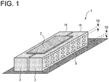
- FIG. 1 is a perspective view of a flexible mandrel 1 according to at least one embodiment of the present invention.
- FIG. 2 is a modification of FIG. 1 .
- a pair of flexible mandrels 1 hereinafter, also separately referred to as "first flexible mandrel 1A” and "second flexible mandrel 1B" having the same shape and a composite material part 2 to be molded are depicted.
- the flexible mandrel 1 is a mold for molding the composite material part 2 and has a shape in conformance with the composite material part 2 to be molded.
- an aircraft stringer having a I-type cross-section and extending in the longitudinal direction is shown as an example of the composite material part 2.
- the first flexible mandrel 1A and the second flexible mandrel 1B have the same shape.
- a composite material for forming the composite material part 2 is placed between these mandrels and molded.
- a body 3 of the flexible mandrel 1 has a substantially square cross-sectional shape.
- the body 3 includes a thermally conductive material for transferring heat from the outside to the composite material part 2 to perform thermal curing treatment.
- the material of the body 3 has flexibility allowing the body 3 to transform in accordance with the designed shape of the composite material part 2.
- Examples of the material used in the flexible mandrel 1 include metal, plastic, and composite materials (CFRP, particularly preferably PAN-based CFRP in terms of cost; and PITCH-based CFRP can also be used).
- the body 3 of the flexible mandrel 1 includes a contact surface 4 configured to come into contact with the composite material part 2 and a non-contact surface 6 configured not to come into contact with the composite material part 2.
- the contact surface 4 has a shape in conformance with the composite material part 2 to mold the composite material part 2, while the non-contact surface 6 may have any shape.
- the flexible mandrel 1 includes at least one hole 8.
- the hole 8 is formed from the non-contact surface 6 toward the inside of the body 3 (i.e., The hole 8 opens to the non-contact surface 6), so that the hole 8 does not affect the shape of the composite material part 2.
- the hole 8 in the body 3 it is possible to reduce the heat capacity of the flexible mandrel 1, and it is possible to reduce the temperature rise time in thermal curing treatment.
- the hole 8 is formed in the non-contact surface 6 which does not come into contact with the composite material part 2 during molding, contact between the contact surface 4 and the composite material part 2 is ensured, and heat can be well transferred to the composite material part 2.
- the hole 8 in the present embodiment is formed as a non-through hole having a bottom.
- the hole 8 may have any depth, for instance, a depth of 60% to 90% of a distance L between the contact surface 4 and the non-contact surface 6. By setting the depth of the hole 8 in this range, it is possible to obtain appropriate flexibility and stiffness while precisely reducing the heat capacity of the flexible mandrel 1.
- the hole 8 may be a through hole.
- two openings (inlet and outlet) of the hole 8 are both preferably located in the non-contact surface 6.
- the hole 8 in the present embodiment is substantially straight, the hole 8 may be curved along curve of the body 3, for instance.
- a plurality of holes 8 is provided. By providing a plurality of holes 8, it is possible to effectively reduce the heat capacity while precisely ensuring flexibility and stiffness of the flexible mandrel 1, compared to the case where only a single hole 8 is provided.
- the plurality of holes 8 may be distributed uniformly in at least one region on the non-contact surface 6. In the region where the holes 8 are uniformly distributed, since the heat capacity is reduced by a certain proportion over the entire region, it is possible to uniformly supply heat to the composite material during thermal curing treatment, and it is possible to mold the composite material with high quality.
- the holes 8 are formed in the non-contact surface 6 except for a non-formation region 10 including an edge of the body 3.
- the non-formation region 10 may be formed with a thickness of, for instance, 10% or more of the total thickness of the non-contact surface 6 in a thickness direction along the plane perpendicular to the longitudinal direction of the composite material part 2.
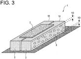
- FIG. 3 is a modification of FIG. 1 .
- the plurality of holes 8 is formed non-uniformly in at least one region on the non-contact surface 6.
- the distribution of such holes 8 may be random, or may be set in accordance with the shape of the composite material part 2 so that predetermined temperature distribution and stress distribution can be obtained when the flexible mandrel 1 is transformed in accordance with the shape of the composite material part 2.
- thermal curing treatment it is possible to control the amount of heat transferred to the composite material part 2, and it is possible to mold the composite material with high quality.
- FIG. 4 is a modification of FIG. 2 .
- This modification further includes a filler 12 filled in the hole 8.
- a filler 12 filled in the hole 8.
- the filler 12 filled in the hole 8 may include a material having a thermal conductivity higher than the body 3. In this case, it is possible to further improve the thermal conductivity of the body 3 by the filler 12, and it is possible to more rapidly raise the temperature.
- a metal foam is useful, for instance.
- a lightweight material excellent in thermal conductivity such as aluminum foam is preferably used.
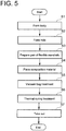
- FIG. 5 is a flowchart of steps of the method of manufacturing the composite material part 2 according to at least one embodiment of the present invention.
- the body 3 of the flexible mandrel 1 is formed from a predetermined material (step S1).
- the material of the body 3 has a thermal conductivity capable of transferring heat supplied from the outside to the composite material part 2 during thermal curing treatment and a flexibility allowing the body 3 to transform in accordance with the designed shape of the composite material part 2.
- metal and composite materials may be used (CFRP, PAN-based CFRP is particularly preferable in terms of cost, and PITCH-based CFRP can also be used).
- Such a body 3 is formed as a substantially rectangular solid bulk.
- step S2 at least one hole 8 is formed in the body 3 formed in step S1 (step S2).
- the hole 8 is formed by machining, for instance cutting, the bulk of the body 3.
- the hole 8 may be formed simultaneously when the body 3 is formed in step S1 (for instance, the body 3 and the hole 8 may be integrally formed).
- the at least one hole 8 is formed in the non-contact surface 6 of the body 3 which does not come into contact with the composite material part 2.
- the hole 8 may be formed in the non-contact surface 6 except for a non-formation region 10 including an edge of the body 3.
- the distribution may be uniform or non-uniform.
- the hole 8 thus formed is filled with a filler 12, as needed.
- the filler 12 may include a material having a thermal conductivity higher than the body 3. For instance, metal foam such as aluminum foam can be used.
- the composite material part 2 is molded with the flexible mandrel 1 thus completed.
- a pair of the flexible mandrels 1 is prepared (step S3), and a composite material for forming the composite material part 2 is placed between the pair of flexible mandrels 1 (step S4).
- the composite material to be used may be, for instance, semi-cured flexible CFRP sheets which are combined in accordance with the shape of the composite material part 2.
- FIG. 6 is a schematic diagram showing combination pattern of CFRP sheets for molding the composite material part 2 having a I-type cross-section.
- a first sheet 2A covering the contact surface 4 of the first flexible mandrel 1A
- a second sheet 2B covering the contact surface 4 of the second flexible mandrel 1B
- a third sheet 2C covering the first sheet 2A and the second sheet 2B from above
- a fourth sheet 2D covering the first sheet 2A and the second sheet 2B from above are combined.
- vacuum bag treatment is performed by covering the entire assembly with a bag material and eliminating air therein (step S5).
- the bag material is somewhat drawn into the hole 8 formed in the body 3 due to negative pressure.
- the hole 8 is filled with the filler 12 as in the second modification ( FIG. 4 ), it is possible to effectively prevent the bag material being drawn into the hole 8 and damaged.
- thermal curing treatment is performed on the pair of flexible mandrels 1 with the composite material placed therebetween (step S6).
- the thermal curing treatment is performed in an autoclave at high temperature and high pressure. When the atmosphere temperature in the autoclave rises, heat is transferred to the composite material via the flexible mandrels 1, so that the composite material is heated.
- FIG. 7 is measurement result showing the time course of the temperature inside the flexible mandrels 1 and the atmosphere temperature in the autoclave in thermal curing treatment.
- the dotted line represents the atmosphere temperature in the autoclave.
- the atmosphere temperature gradually increases to target temperature TO over time. With the change in the atmosphere temperature, the temperature inside the flexible mandrels 1 increases accordingly.
- Measurement result represented by the solid line is result of comparative example not having the hole 8 (same as the flexible mandrel 1 according to the present embodiment except for the absence of the hole 8), and measurement result represented by the alternate long and short dash line is result of the flexible mandrel 1 having the hole 8 according to the present embodiment.
- the time for reaching the target temperature T0 was about 53 minutes earlier than comparative example. This indicates that the flexible mandrel 1 having the hole 8 according to the present embodiment has reduced heat capacity and thus can be more rapidly heated.
- step S6 In thermal curing treatment of step S6, since the temperature is kept at the target temperature for a predetermined time, thermal curing of the composite material progresses, and the composite material part 2 is molded. After completion of thermal curing treatment, the bag material is removed, and the finished composite material part 2 is taken out from the inside (step S7).
- thermosetting resin As described above, according to at least one embodiment of the present invention, by forming the hole 8 in the body of the flexible mandrel 1, temperature rising for thermally curing the composite material containing a thermosetting resin is promoted. Thus, it is possible to achieve the improvement in part production rate and the reduction in cost.
- At least one embodiment of the present invention can be applied to a flexible mandrel used for molding a composite material part including a composite material such as CFRP and a method of manufacturing a composite material part with the flexible mandrel.
Landscapes
- Engineering & Computer Science (AREA)
- Mechanical Engineering (AREA)
- Chemical & Material Sciences (AREA)
- Composite Materials (AREA)
- Moulding By Coating Moulds (AREA)
- Moulds For Moulding Plastics Or The Like (AREA)
Abstract
Description
- The present disclosure relates to a flexible mandrel used for molding a composite material part including a composite material such as CFRP and a method of manufacturing a composite material part with the flexible mandrel.
- Composite materials typified by carbon fiber reinforced plastic (CFRP) are excellent in strength and stiffness compared to typical metal materials, and are widely used for structures such as aircrafts and space machines with a need for reduced weight. CFRP mainly uses a thermosetting resin such as epoxy resin, and is molded by thermally curing the composite material in a chamber called an autoclave at high temperature and high pressure.
- One example of the composite material part is a stringer for reinforcing a plate member used in an aircraft. The stringer has a complex shape including contours and twists in accordance with airframe designs, for example, I-type cross-sectional shape. Such a stringer is molded by stacking semi-cured flexible CFRP sheets (composite material) between a pair of mold mandrels, surrounding the assembly by a vacuum bag and eliminating air therein to bring the composite material into close contact with the mandrels, and subjecting the composite material to thermal curing treatment.
-
Patent Document 1 discloses a metal mandrel used for producing such a stringer, in which slots are formed in a depth direction to improve flexibility and generate complex shapes (contours and twists). - Patent Document 1:
JP4896035B - The mandrel used for molding a composite material containing a thermosetting resin as disclose in
Patent Document 1 has a higher heat capacity than the composite material to be molded. Accordingly, it takes a long time to sufficiently raise the temperature for thermally curing the composite material to be molded, which leads to a reduction in part production rate and an increase in power consumed for thermal curing treatment, resulting in increased cost. - At least one embodiment of the present invention was made in view of the above circumstances, and an object thereof is to provide a flexible mandrel and a method of manufacturing a composite material part that can improve the part production rate and reduce the cost by promoting temperature rising for thermally curing a composite material containing a thermosetting resin.
-
- (1) To solve the above problems, a flexible mandrel for molding a composite material containing a thermosetting resin according to at least one embodiment of the present invention comprises: a body including a contact surface configured to come into contact with the composite material during molding and a non-contact surface configured not to come into contact with the composite material during molding; and at least one hole formed from the non-contact surface toward an inside of the body.
With the above configuration (1), at least one hole is provided in the body of the flexible mandrel. By providing the hole, it is possible to reduce the heat capacity of the flexible mandrel. Further, since the hole is formed in the non-contact surface which does not come into contact with the composite material during molding, contact between the composite material and the contact surface is well ensured. Thus, it is possible to effectively reduce the time required for raising the temperature in thermal curing treatment, and it is possible to improve the part production rate and reduce the cost. - (2) In some embodiments, in the above configuration (1), the at least one hole is formed in a portion of the non-contact surface opposite to the contact surface.
With the above configuration (2), since the hole is formed in a portion of the non-contact surface opposite to the contact surface, contact between the composite material and the contact surface is well ensured. - (3) In some embodiments, in the above configuration (1) or (2), the at least one hole includes a plurality of holes uniformly formed in at least one region on the non-contact surface.
With the above configuration (3), in the region where the holes are uniformly distributed, since the heat capacity is reduced by a certain proportion over the entire region, it is possible to uniformly supply heat to the composite material during thermal curing treatment, and it is possible to mold the composite material with high quality. - (4) In some embodiments, in the above configuration (1) or (2), the at least one hole includes a plurality of holes non-uniformly formed in at least one region on the non-contact surface.
With the above configuration (4), the holes may be distributed non-uniformly in at least one region so that predetermined temperature distribution and stress are applied to the composite material when the flexible mandrel is transformed in accordance with the shape of the target. Thereby, it is possible to perform thermal curing treatment in accordance with the shape of the composite material at the time of thermal curing treatment, and it is possible to manufacture the composite material part with high quality. - (5) In some embodiments, in any one of the above configurations (1) to (4), the at least one hole is formed in the non-contact surface except for a non-formation region including an edge.
With the above configuration (5), by providing the non-formation region, where no hole is formed, in the vicinity of the edge, it is possible to obtain sufficient strength while ensuring flexibility of the mandrel. Thus, it is possible to favorably prevent damage in molding. - (6) In some embodiments, in the above configuration (5), the non-formation region has a thickness of 10% or more of a total thickness of the non-contact surface in a thickness direction along a plane perpendicular to a longitudinal direction of a composite material part made of the composite material.
With the above configuration (6), by setting the non-formation region having no hole in this range, it is possible to obtain sufficient strength while ensuring flexibility of the mandrel. - (7) In some embodiments, in any one of the above configurations (1) to (6), the at least one hole is a bottomed hole having a depth of 60% to 90% of a distance between the contact surface and the non-contact surface.
With the above configuration (7), by setting the depth of the hole in this range, it is possible to obtain appropriate flexibility and strength while precisely reducing the heat capacity of the flexible mandrel. - (8) In some embodiments, in any one of the above configurations (1) to (7), the flexible mandrel further comprises a filler filled in the at least one hole.
With the above configuration (8), by filling the hole with the filler, it is possible to flatten the non-contact surface having the hole. Thereby, for instance, when vacuum bag treatment is performed in thermal curing treatment, it is possible to prevent the bag material being drawn into the hole and damaged. - (9) In some embodiments, in the above configuration (8), the filler has a thermal conductivity higher than the body.
With the above configuration (9), by using a material having higher thermal conductivity than the body as the filler, it is possible to further improve the thermal conductivity of the flexible mandrel and more rapidly raise the temperature. - (10) In some embodiments, in the above configuration (8) or (9), the filler is a metal foam.
With the above configuration (10), as the filler, a lightweight metal foam excellent in heat conductivity such as aluminum foam is used. - (11) To solve the above problems, a method of manufacturing a composite material part by molding a composite material containing a thermosetting resin with a pair of flexible mandrels according to at least one embodiment of the present invention comprises: a step of forming a body of each flexible mandrel including a contact surface configured to come into contact with the composite material and a non-contact surface configured not to come into contact with the composite material; a step of forming at least one hole in the non-contact surface of the body toward an inside of the body; and a step of placing the composite material between the pair of flexible mandrels having the at least one hole and subjecting the composite material to thermal curing treatment.
With the above method (11), by using the flexible mandrel (including various embodiments described above), it is possible to promote temperature rising for thermally curing the composite material containing a thermosetting resin. - According to at least one embodiment of the present invention, there is provided a flexible mandrel and a method of manufacturing a composite material part that can improve the part production rate and reduce the cost by promoting temperature rising for thermally curing a composite material containing a thermosetting resin.
-
-
FIG. 1 is a perspective view of a flexible mandrel according to at least one embodiment of the present invention. -
FIG. 2 is a cross-sectional view ofFIG. 1 . -
FIG. 3 shows a modification ofFIG. 1 . -
FIG. 4 shows a modification ofFIG. 2 . -
FIG. 5 is a flowchart of steps of a method of manufacturing a composite material part according to at least one embodiment of the present invention. -
FIG. 6 is a schematic diagram showing combination pattern of CFRP sheets for molding a composite material part having a I-type cross-section. -
FIG. 7 is measurement result showing the time course of the temperature inside flexible mandrels and the atmosphere temperature in an autoclave in thermal curing treatment. - Embodiments of the present invention will now be described in detail with reference to the accompanying drawings. It is intended, however, that unless particularly identified, dimensions, materials, shapes, relative positions and the like of components described in the embodiments shall be interpreted as illustrative only and not intended to limit the scope of the present invention.
- For instance, an expression of relative or absolute arrangement such as "in a direction", "along a direction", "parallel", "orthogonal", "centered", "concentric" and "coaxial" shall not be construed as indicating only the arrangement in a strict literal sense, but also includes a state where the arrangement is relatively displaced by a tolerance, or by an angle or a distance whereby it is possible to achieve the same function.
- Further, for instance, an expression of a shape such as a rectangular shape or a cylindrical shape shall not be construed as only the geometrically strict shape, but also includes a shape with unevenness or chamfered corners within the range in which the same effect can be achieved.
- On the other hand, an expression such as "comprise", "include", "have", "contain" and "constitute" are not intended to be exclusive of other components.
- The following embodiments will be described in conjunction with a case where the composite material is a carbon fiber reinforced plastic (CFRP) composed of carbon fiber reinforced with resin, containing a thermosetting resin such as epoxy resin, unsaturated polyester, vinyl ester, phenol, cyanate ester, or polyimide, which can be molded by thermal curing treatment.
- As the reinforcing fiber of the composite material, besides carbon fiber, glass fiber, boron fiber, or aramid fiber can also be used.
- Further, in the following embodiments, a stringer for reinforcing a plate member used in an aircraft is mentioned as an example of the composite material part obtained by molding the composite material. However, the present disclosure can be applied to various parts within a range of technical ideas. In particular, it can be applied to structures such as aircrafts and space machines with a need for strength, stiffness, and reduced weight.
- First, a configuration of a flexible mandrel used for molding a composite material part will be described.
FIG. 1 is a perspective view of aflexible mandrel 1 according to at least one embodiment of the present invention.FIG. 2 is a modification ofFIG. 1 . InFIGs. 1 and2 , a pair of flexible mandrels 1 (hereinafter, also separately referred to as "firstflexible mandrel 1A" and "secondflexible mandrel 1B") having the same shape and acomposite material part 2 to be molded are depicted. - The
flexible mandrel 1 is a mold for molding thecomposite material part 2 and has a shape in conformance with thecomposite material part 2 to be molded. In the present embodiment, an aircraft stringer having a I-type cross-section and extending in the longitudinal direction is shown as an example of thecomposite material part 2. The firstflexible mandrel 1A and the secondflexible mandrel 1B have the same shape. InFIG. 1 , a composite material for forming thecomposite material part 2 is placed between these mandrels and molded. - A
body 3 of theflexible mandrel 1 has a substantially square cross-sectional shape. Thebody 3 includes a thermally conductive material for transferring heat from the outside to thecomposite material part 2 to perform thermal curing treatment. The material of thebody 3 has flexibility allowing thebody 3 to transform in accordance with the designed shape of thecomposite material part 2. Examples of the material used in theflexible mandrel 1 include metal, plastic, and composite materials (CFRP, particularly preferably PAN-based CFRP in terms of cost; and PITCH-based CFRP can also be used). - As shown in
FIG. 2 , for molding thecomposite material part 2, thebody 3 of theflexible mandrel 1 includes acontact surface 4 configured to come into contact with thecomposite material part 2 and anon-contact surface 6 configured not to come into contact with thecomposite material part 2. As described above, thecontact surface 4 has a shape in conformance with thecomposite material part 2 to mold thecomposite material part 2, while thenon-contact surface 6 may have any shape. - In this type of flexible mandrel, typically, a solid bulk material is used. In this case, however, since the heat capacity of the flexible mandrel is larger than that of the
composite material part 2 to be molded, the time for raising the temperature in thermal curing treatment increases, which hinders the part production rate and the reduction in cost. In particular, if the body is made of a metal material, the body is heavy and thus is difficult to handle. - To solve such problems, the
flexible mandrel 1 according to the present embodiment includes at least onehole 8. Thehole 8 is formed from thenon-contact surface 6 toward the inside of the body 3 (i.e., Thehole 8 opens to the non-contact surface 6), so that thehole 8 does not affect the shape of thecomposite material part 2. By providing thehole 8 in thebody 3, it is possible to reduce the heat capacity of theflexible mandrel 1, and it is possible to reduce the temperature rise time in thermal curing treatment. Further, since thehole 8 is formed in thenon-contact surface 6 which does not come into contact with thecomposite material part 2 during molding, contact between thecontact surface 4 and thecomposite material part 2 is ensured, and heat can be well transferred to thecomposite material part 2. - The
hole 8 in the present embodiment is formed as a non-through hole having a bottom. Thehole 8 may have any depth, for instance, a depth of 60% to 90% of a distance L between thecontact surface 4 and thenon-contact surface 6. By setting the depth of thehole 8 in this range, it is possible to obtain appropriate flexibility and stiffness while precisely reducing the heat capacity of theflexible mandrel 1. - However, the
hole 8 may be a through hole. In this case, two openings (inlet and outlet) of thehole 8 are both preferably located in thenon-contact surface 6. Further, although thehole 8 in the present embodiment is substantially straight, thehole 8 may be curved along curve of thebody 3, for instance. - In the present embodiment, a plurality of
holes 8 is provided. By providing a plurality ofholes 8, it is possible to effectively reduce the heat capacity while precisely ensuring flexibility and stiffness of theflexible mandrel 1, compared to the case where only asingle hole 8 is provided. - Further, as shown in
FIGs. 1 and2 , the plurality ofholes 8 may be distributed uniformly in at least one region on thenon-contact surface 6. In the region where theholes 8 are uniformly distributed, since the heat capacity is reduced by a certain proportion over the entire region, it is possible to uniformly supply heat to the composite material during thermal curing treatment, and it is possible to mold the composite material with high quality. - The
holes 8 are formed in thenon-contact surface 6 except for anon-formation region 10 including an edge of thebody 3. By providing thenon-formation region 10 in the vicinity of the edge on which stress is likely to concentrate during molding, it is possible to obtain sufficient strength while ensuring flexibility of the mandrel. Thus, it is possible to prevent damage in molding. - The
non-formation region 10 may be formed with a thickness of, for instance, 10% or more of the total thickness of thenon-contact surface 6 in a thickness direction along the plane perpendicular to the longitudinal direction of thecomposite material part 2. By setting thenon-formation region 10 in this range, it is possible to more effectively obtain sufficient strength while ensuring flexibility of the mandrel. -
FIG. 3 is a modification ofFIG. 1 . In this modification, the plurality ofholes 8 is formed non-uniformly in at least one region on thenon-contact surface 6. The distribution ofsuch holes 8 may be random, or may be set in accordance with the shape of thecomposite material part 2 so that predetermined temperature distribution and stress distribution can be obtained when theflexible mandrel 1 is transformed in accordance with the shape of thecomposite material part 2. Thus, in thermal curing treatment, it is possible to control the amount of heat transferred to thecomposite material part 2, and it is possible to mold the composite material with high quality. -
FIG. 4 is a modification ofFIG. 2 . This modification further includes afiller 12 filled in thehole 8. By filling thehole 8 with thefiller 12, it is possible to flatten thenon-contact surface 6 having thehole 8. Thereby, for instance, when vacuum bag treatment is performed in thermal curing treatment, it is possible to prevent the bag material being drawn into thehole 8 and damaged (see step S5 ofFIG. 5 ). - The
filler 12 filled in thehole 8 may include a material having a thermal conductivity higher than thebody 3. In this case, it is possible to further improve the thermal conductivity of thebody 3 by thefiller 12, and it is possible to more rapidly raise the temperature. As the material of thefiller 12, a metal foam is useful, for instance. Specifically, a lightweight material excellent in thermal conductivity such as aluminum foam is preferably used. - Next, a method of manufacturing the
composite material part 2 with theflexible mandrel 1 having the above configuration will be described.FIG. 5 is a flowchart of steps of the method of manufacturing thecomposite material part 2 according to at least one embodiment of the present invention. - First, the
body 3 of theflexible mandrel 1 is formed from a predetermined material (step S1). As described above, the material of thebody 3 has a thermal conductivity capable of transferring heat supplied from the outside to thecomposite material part 2 during thermal curing treatment and a flexibility allowing thebody 3 to transform in accordance with the designed shape of thecomposite material part 2. For instance, metal and composite materials may be used (CFRP, PAN-based CFRP is particularly preferable in terms of cost, and PITCH-based CFRP can also be used). - Such a
body 3 is formed as a substantially rectangular solid bulk. - Then, at least one
hole 8 is formed in thebody 3 formed in step S1 (step S2). Thehole 8 is formed by machining, for instance cutting, the bulk of thebody 3. Although in the present embodiment, thehole 8 is formed after forming thebulk body 3, thehole 8 may be formed simultaneously when thebody 3 is formed in step S1 (for instance, thebody 3 and thehole 8 may be integrally formed). - The at least one
hole 8 is formed in thenon-contact surface 6 of thebody 3 which does not come into contact with thecomposite material part 2. Thehole 8 may be formed in thenon-contact surface 6 except for anon-formation region 10 including an edge of thebody 3. When a plurality ofholes 8 is formed, the distribution may be uniform or non-uniform. - The
hole 8 thus formed is filled with afiller 12, as needed. Thefiller 12 may include a material having a thermal conductivity higher than thebody 3. For instance, metal foam such as aluminum foam can be used. - Then, the
composite material part 2 is molded with theflexible mandrel 1 thus completed. A pair of theflexible mandrels 1 is prepared (step S3), and a composite material for forming thecomposite material part 2 is placed between the pair of flexible mandrels 1 (step S4). The composite material to be used may be, for instance, semi-cured flexible CFRP sheets which are combined in accordance with the shape of thecomposite material part 2. -
FIG. 6 is a schematic diagram showing combination pattern of CFRP sheets for molding thecomposite material part 2 having a I-type cross-section. For molding thecomposite material part 2 having the I-type cross-section as shown inFIG. 1 , for instance, afirst sheet 2A covering thecontact surface 4 of the firstflexible mandrel 1A, asecond sheet 2B covering thecontact surface 4 of the secondflexible mandrel 1B, athird sheet 2C covering thefirst sheet 2A and thesecond sheet 2B from above, and afourth sheet 2D covering thefirst sheet 2A and thesecond sheet 2B from above are combined. - Then, while the composite material is placed between the pair of
flexible mandrels 1, vacuum bag treatment is performed by covering the entire assembly with a bag material and eliminating air therein (step S5). In vacuum bag treatment, the bag material is somewhat drawn into thehole 8 formed in thebody 3 due to negative pressure. However, when thehole 8 is filled with thefiller 12 as in the second modification (FIG. 4 ), it is possible to effectively prevent the bag material being drawn into thehole 8 and damaged. - Then, while assembly is vacuum bagged, thermal curing treatment is performed on the pair of
flexible mandrels 1 with the composite material placed therebetween (step S6). The thermal curing treatment is performed in an autoclave at high temperature and high pressure. When the atmosphere temperature in the autoclave rises, heat is transferred to the composite material via theflexible mandrels 1, so that the composite material is heated. -
FIG. 7 is measurement result showing the time course of the temperature inside theflexible mandrels 1 and the atmosphere temperature in the autoclave in thermal curing treatment. InFIG. 7 , the dotted line represents the atmosphere temperature in the autoclave. The atmosphere temperature gradually increases to target temperature TO over time. With the change in the atmosphere temperature, the temperature inside theflexible mandrels 1 increases accordingly. Measurement result represented by the solid line is result of comparative example not having the hole 8 (same as theflexible mandrel 1 according to the present embodiment except for the absence of the hole 8), and measurement result represented by the alternate long and short dash line is result of theflexible mandrel 1 having thehole 8 according to the present embodiment. As shown inFIG. 7 , in the present embodiment, the time for reaching the target temperature T0 was about 53 minutes earlier than comparative example. This indicates that theflexible mandrel 1 having thehole 8 according to the present embodiment has reduced heat capacity and thus can be more rapidly heated. - In thermal curing treatment of step S6, since the temperature is kept at the target temperature for a predetermined time, thermal curing of the composite material progresses, and the
composite material part 2 is molded. After completion of thermal curing treatment, the bag material is removed, and the finishedcomposite material part 2 is taken out from the inside (step S7). - As described above, according to at least one embodiment of the present invention, by forming the
hole 8 in the body of theflexible mandrel 1, temperature rising for thermally curing the composite material containing a thermosetting resin is promoted. Thus, it is possible to achieve the improvement in part production rate and the reduction in cost. - At least one embodiment of the present invention can be applied to a flexible mandrel used for molding a composite material part including a composite material such as CFRP and a method of manufacturing a composite material part with the flexible mandrel.
-
- 1
- Flexible mandrel
- 2
- Composite material part
- 3
- Body
- 4
- Contact surface
- 6
- Non-contact surface
- 8
- Hole
- 10
- Non-formation region
- 12
- Filler
Claims (11)
- A flexible mandrel for molding a composite material containing a thermosetting resin, comprising:a body including a contact surface configured to come into contact with the composite material during molding and a non-contact surface configured not to come into contact with the composite material during molding; andat least one hole formed from the non-contact surface toward an inside of the body.
- The flexible mandrel according to claim 1,
wherein the at least one hole is formed in a portion of the non-contact surface opposite to the contact surface. - The flexible mandrel according to claim 1 or 2,
wherein the at least one hole includes a plurality of holes uniformly formed in at least one region on the non-contact surface. - The flexible mandrel according to claim 1 or 2,
wherein the at least one hole includes a plurality of holes non-uniformly formed in at least one region on the non-contact surface. - The flexible mandrel according to any one of claims 1 to 4,
wherein the at least one hole is formed in the non-contact surface except for a non-formation region including an edge. - The flexible mandrel according to claim 5,
wherein the non-formation region has a thickness of 10% or more of a total thickness of the non-contact surface in a thickness direction along a plane perpendicular to a longitudinal direction of a composite material part made of the composite material. - The flexible mandrel according to any one of claims 1 to 6,
wherein the at least one hole is a bottomed hole having a depth of 60% to 90% of a distance between the contact surface and the non-contact surface. - The flexible mandrel according to any one of claims 1 to 7, further comprising a filler filled in the at least one hole.
- The flexible mandrel according to claim 8,
wherein the filler has a thermal conductivity higher than the body. - The flexible mandrel according to claim 8 or 9,
wherein the filler is a metal foam. - A method of manufacturing a composite material part by molding a composite material containing a thermosetting resin with a pair of flexible mandrels, the method comprising:a step of forming a body of each flexible mandrel including a contact surface configured to come into contact with the composite material and a non-contact surface configured not to come into contact with the composite material;a step of forming at least one hole in the non-contact surface of the body toward an inside of the body; anda step of placing the composite material between the pair of flexible mandrels having the at least one hole and subjecting the composite material to thermal curing treatment.
Applications Claiming Priority (2)
| Application Number | Priority Date | Filing Date | Title |
|---|---|---|---|
| JP2017150649A JP6971690B2 (en) | 2017-08-03 | 2017-08-03 | Manufacturing method for flexible mandrel and composite parts |
| PCT/JP2018/021826 WO2019026418A1 (en) | 2017-08-03 | 2018-06-07 | Flexible mandrel, and method for producing composite material component |
Publications (2)
| Publication Number | Publication Date |
|---|---|
| EP3636421A1 true EP3636421A1 (en) | 2020-04-15 |
| EP3636421A4 EP3636421A4 (en) | 2020-06-03 |
Family
ID=65233675
Family Applications (1)
| Application Number | Title | Priority Date | Filing Date |
|---|---|---|---|
| EP18841948.5A Withdrawn EP3636421A4 (en) | 2017-08-03 | 2018-06-07 | Flexible mandrel, and method for producing composite material component |
Country Status (4)
| Country | Link |
|---|---|
| US (1) | US11148326B2 (en) |
| EP (1) | EP3636421A4 (en) |
| JP (1) | JP6971690B2 (en) |
| WO (1) | WO2019026418A1 (en) |
Family Cites Families (7)
| Publication number | Priority date | Publication date | Assignee | Title |
|---|---|---|---|---|
| US5502886A (en) * | 1994-09-02 | 1996-04-02 | The Boeing Company | Composite stringer disassembly machine |
| JPH10244598A (en) * | 1997-03-03 | 1998-09-14 | Sekisui Chem Co Ltd | Method of manufacturing reinforced resin curved pipe |
| US7357166B2 (en) | 2004-11-24 | 2008-04-15 | The Boeing Company | Flexible mandrel for highly contoured composite stringer |
| JP5588645B2 (en) * | 2009-09-15 | 2014-09-10 | 川崎重工業株式会社 | Jig for manufacturing a composite material structure having a thick portion in a cross section |
| JP5416554B2 (en) * | 2009-11-06 | 2014-02-12 | 川崎重工業株式会社 | Jig for manufacturing composite material structures |
| US8534339B2 (en) * | 2011-10-12 | 2013-09-17 | The Boeing Company | Lightweight flexible mandrel and method for making the same |
| US9701070B2 (en) * | 2014-11-06 | 2017-07-11 | Lockheed Martin Corporation | Mandrel forming for discrete wing skin stiffeners |
-
2017
- 2017-08-03 JP JP2017150649A patent/JP6971690B2/en active Active
-
2018
- 2018-06-07 EP EP18841948.5A patent/EP3636421A4/en not_active Withdrawn
- 2018-06-07 WO PCT/JP2018/021826 patent/WO2019026418A1/en not_active Ceased
- 2018-06-07 US US16/623,218 patent/US11148326B2/en active Active
Also Published As
| Publication number | Publication date |
|---|---|
| US20200198188A1 (en) | 2020-06-25 |
| WO2019026418A1 (en) | 2019-02-07 |
| JP6971690B2 (en) | 2021-11-24 |
| JP2019025869A (en) | 2019-02-21 |
| US11148326B2 (en) | 2021-10-19 |
| EP3636421A4 (en) | 2020-06-03 |
Similar Documents
| Publication | Publication Date | Title |
|---|---|---|
| CN101489769B (en) | Composite Manufacturing Method | |
| EP2903801B1 (en) | Composite structure having a stabilizing element | |
| CN109562578B (en) | Composite structure and method of manufacturing composite structure | |
| JP6104730B2 (en) | Mold and molding method of composite material | |
| KR102022130B1 (en) | Lightweight flexible mandrel and method for making the same | |
| EP2939820B1 (en) | Method and device for manufacturing a composite part of an aircraft | |
| US10688736B2 (en) | Composite materials molding method, and composite materials | |
| KR20170024527A (en) | Textured caul plate and method of use | |
| JP2003071864A (en) | Manufacturing method of composite reinforcing plate | |
| JPWO2019188195A1 (en) | Manufacturing method of fiber reinforced plastic | |
| EP3620295A1 (en) | Flexible mandrel, and method for producing composite material component | |
| JP2019001024A (en) | Composite wing molding method | |
| US11148326B2 (en) | Flexible mandrel and method of manufacturing composite material part | |
| JP4941811B2 (en) | Manufacturing method of preform and FRP molded body | |
| US11633881B1 (en) | Heated composite tool and method for building and use | |
| EP3782803A1 (en) | Highly contoured composite structures and system and method for making the same | |
| US20250074017A1 (en) | Production system |
Legal Events
| Date | Code | Title | Description |
|---|---|---|---|
| STAA | Information on the status of an ep patent application or granted ep patent |
Free format text: STATUS: THE INTERNATIONAL PUBLICATION HAS BEEN MADE |
|
| PUAI | Public reference made under article 153(3) epc to a published international application that has entered the european phase |
Free format text: ORIGINAL CODE: 0009012 |
|
| STAA | Information on the status of an ep patent application or granted ep patent |
Free format text: STATUS: REQUEST FOR EXAMINATION WAS MADE |
|
| 17P | Request for examination filed |
Effective date: 20200110 |
|
| AK | Designated contracting states |
Kind code of ref document: A1 Designated state(s): AL AT BE BG CH CY CZ DE DK EE ES FI FR GB GR HR HU IE IS IT LI LT LU LV MC MK MT NL NO PL PT RO RS SE SI SK SM TR |
|
| AX | Request for extension of the european patent |
Extension state: BA ME |
|
| A4 | Supplementary search report drawn up and despatched |
Effective date: 20200504 |
|
| RIC1 | Information provided on ipc code assigned before grant |
Ipc: B29C 70/54 20060101AFI20200424BHEP Ipc: B29C 70/44 20060101ALI20200424BHEP Ipc: B29C 70/06 20060101ALI20200424BHEP Ipc: B29D 99/00 20100101ALI20200424BHEP Ipc: B29K 105/08 20060101ALI20200424BHEP |
|
| DAV | Request for validation of the european patent (deleted) | ||
| DAX | Request for extension of the european patent (deleted) | ||
| STAA | Information on the status of an ep patent application or granted ep patent |
Free format text: STATUS: EXAMINATION IS IN PROGRESS |
|
| 17Q | First examination report despatched |
Effective date: 20210401 |
|
| STAA | Information on the status of an ep patent application or granted ep patent |
Free format text: STATUS: THE APPLICATION HAS BEEN WITHDRAWN |
|
| 18W | Application withdrawn |
Effective date: 20210716 |