EP3636370A1 - Drill - Google Patents
Drill Download PDFInfo
- Publication number
- EP3636370A1 EP3636370A1 EP18880079.1A EP18880079A EP3636370A1 EP 3636370 A1 EP3636370 A1 EP 3636370A1 EP 18880079 A EP18880079 A EP 18880079A EP 3636370 A1 EP3636370 A1 EP 3636370A1
- Authority
- EP
- European Patent Office
- Prior art keywords
- cutting edge
- center axis
- distance
- equal
- drill
- Prior art date
- Legal status (The legal status is an assumption and is not a legal conclusion. Google has not performed a legal analysis and makes no representation as to the accuracy of the status listed.)
- Pending
Links
Images




Classifications
-
- B—PERFORMING OPERATIONS; TRANSPORTING
- B23—MACHINE TOOLS; METAL-WORKING NOT OTHERWISE PROVIDED FOR
- B23B—TURNING; BORING
- B23B51/00—Tools for drilling machines
- B23B51/10—Bits for countersinking
- B23B51/108—Bits for countersinking having a centering drill
-
- B—PERFORMING OPERATIONS; TRANSPORTING
- B23—MACHINE TOOLS; METAL-WORKING NOT OTHERWISE PROVIDED FOR
- B23B—TURNING; BORING
- B23B51/00—Tools for drilling machines
- B23B51/02—Twist drills
-
- B—PERFORMING OPERATIONS; TRANSPORTING
- B23—MACHINE TOOLS; METAL-WORKING NOT OTHERWISE PROVIDED FOR
- B23B—TURNING; BORING
- B23B2215/00—Details of workpieces
- B23B2215/04—Aircraft components
-
- B—PERFORMING OPERATIONS; TRANSPORTING
- B23—MACHINE TOOLS; METAL-WORKING NOT OTHERWISE PROVIDED FOR
- B23B—TURNING; BORING
- B23B2226/00—Materials of tools or workpieces not comprising a metal
- B23B2226/27—Composites
- B23B2226/275—Carbon fibre reinforced carbon composites
-
- B—PERFORMING OPERATIONS; TRANSPORTING
- B23—MACHINE TOOLS; METAL-WORKING NOT OTHERWISE PROVIDED FOR
- B23B—TURNING; BORING
- B23B2251/00—Details of tools for drilling machines
- B23B2251/04—Angles, e.g. cutting angles
-
- B—PERFORMING OPERATIONS; TRANSPORTING
- B23—MACHINE TOOLS; METAL-WORKING NOT OTHERWISE PROVIDED FOR
- B23B—TURNING; BORING
- B23B2251/00—Details of tools for drilling machines
- B23B2251/12—Cross sectional views of the cutting edges
- B23B2251/127—Sharp cutting edges
-
- B—PERFORMING OPERATIONS; TRANSPORTING
- B23—MACHINE TOOLS; METAL-WORKING NOT OTHERWISE PROVIDED FOR
- B23B—TURNING; BORING
- B23B2251/00—Details of tools for drilling machines
- B23B2251/18—Configuration of the drill point
Definitions
- the present disclosure relates to a drill.
- Patent Literature 1 As a structural material for the body and wings of an airplane, there has been used a layered body in which a fiber reinforced plastic (FRP) layer, such as a carbon fiber reinforced plastic (CFRP) layer, and a metal layer are layered.
- FRP fiber reinforced plastic
- CFRP carbon fiber reinforced plastic
- Patent Literature 1 a drill described in Patent Literature 1 has been utilized.
- the drill of Patent Literature 1 has a cutting edge at a front end of a main body portion. The cutting edge extends from the center of rotation to an outer periphery and is symmetrical with respect to the center of rotation.
- This cutting edge is at least constituted of the following three portions: a rotation center portion; an intermediate cutting edge portion continuous to an outer end of the rotation center portion; and an outermost peripheral cutting edge portion having a straight-line shape and continuous to the outer end of the intermediate cutting edge portion. Respective point angles of the cutting edge portions are decreased in stages from the cutting edge portion at the center of rotation side to the cutting edge portion at the outer peripheral side.
- a drill according to the present disclosure includes a body having a front end and a back end opposite to the front end.
- the body includes a first cutting edge, a second cutting edge apart from the first cutting edge to the back end side relative to the first cutting edge, an outer peripheral portion, and a flank face.
- the outer peripheral portion is provided with: a helical flute extending along a center axis of the body; and a recess that extends in a direction crossing the center axis and that traverses the outer peripheral portion.
- the center axis of the body extends from the front end to the back end.
- the recess includes: a first surface continuous to the outer peripheral portion and extending from the outer peripheral portion toward the center axis; and a second surface continuous to the first surface and extending from the first surface to the front end side of the body.
- the first cutting edge is constituted of a first ridgeline formed by the flank face and a surface of the helical flute.
- the second cutting edge is constituted of a second ridgeline formed by the first surface and the surface of the helical flute.
- a second outer end of the second cutting edge is located at the center axis side relative to the first outer end of the first cutting edge.
- ring-shaped swarf When perforating the layered body by moving the drill of Patent Literature 1 into the layered body from the FRP layer side toward the metal layer side, ring-shaped swarf may be generated in the metal layer.
- One embodiment of the present invention has been made to solve the foregoing problem, and has an object to provide a drill that can suppress ring-shaped swarf from being generated in a workpiece when perforating the workpiece.
- ring-shaped swarf can be suppressed from being generated in a workpiece when perforating the workpiece.
- Drill 1 is used to perforate a workpiece, for example.
- the workpiece is a layered body in which a fiber reinforced plastic (FRP) layer, such as a carbon fiber reinforced plastic (CFRP) layer or a glass fiber reinforced plastic (GFRP) layer, and a metal layer are layered, for example.
- FRP fiber reinforced plastic
- CFRP carbon fiber reinforced plastic
- GFRP glass fiber reinforced plastic
- drill 1 includes a body 2 and a shank 3.
- Body 2 includes a front end 2a and a back end 2b opposite to front end 2a.
- Body 2 is composed of cemented carbide, for example.
- a diamond coating may be provided on a surface of body 2.
- Shank 3 is provided on back end 2b of body 2.
- Shank 3 is a grip to be held by a machine tool during use.
- Body 2 has a center axis A.
- Center axis A is an axis serving as the center of rotation of drill 1.
- Center axis A of body 2 extends from front end 2a to back end 2b.
- Body 2 includes an outer peripheral portion 4.
- Outer peripheral portion 4 includes an outer peripheral surface 5, which is an outer peripheral side surface of body 2.
- Outer peripheral portion 4 may further include a margin 6.
- Margin 6 is provided at a leading edge (front edge portion of outer peripheral portion 4 in a rotation direction C of drill 1 (see Fig. 3 )) of outer peripheral portion 4, and protrudes from outer peripheral surface 5.
- Margin 6 forms a space between the workpiece and outer peripheral surface 5 of a first portion 2p during processing of the workpiece so as to prevent outer peripheral surface 5 from coming into contact with the workpiece.
- Outer peripheral portion 4 is provided with a helical flute 8 extending along center axis A of body 2.
- Helical flute 8 is formed to extend from front end 2a to a vicinity of back end 2b.
- Helical flute 8 is formed in the form of a helix around center axis A. Swarf cut out from the workpiece during processing of the workpiece is released via helical flute 8.
- a plurality of helical flutes 8 may be formed.
- a helix angle ⁇ of helical flute 8 may be more than or equal to 10°, or may be more than or equal to 20°, for example.
- Helix angle ⁇ of helical flute 8 may be less than or equal to 40°, or may be less than or equal to 30°, for example.
- helix angle ⁇ of helical flute 8 is an angle between center axis A and the extending direction of helical flute 8.
- Body 2 includes first portion 2p and a second portion 2q, and is provided with a recess 20 between first portion 2p and second portion 2q.
- First portion 2p includes front end 2a of body 2.
- Second portion 2q includes back end 2b of body 2.
- the diameter of second portion 2q becomes gradually larger from the recess 20 side of second portion 2q toward the back end 2b side of second portion 2q.
- Recess 20 is recessed from outer peripheral portion 4 toward center axis A. Recess 20 is formed by polishing outer peripheral portion 4 using a grindstone, for example.
- first portion 2p includes a first cutting edge 12, a flank face 11, a rake face 10, and outer peripheral portion 4.
- Helical flute 8 extends also to first portion 2p.
- First cutting edge 12 is constituted of first ridgelines formed by flank face 11 and the surface of helical flute 8. A portion of the surface of helical flute 8 constitutes rake face 10.
- First cutting edge 12 includes a first outer end 12a, which is a distal end of first cutting edge 12 relative to center axis A.
- First cutting edge 12 is a single-angle type.
- First cutting edge 12 may be a double-angle type including a first cutting edge portion and a second cutting edge portion, which have point angles different from each other.
- First cutting edge 12 may be a triple-angle type including a first cutting edge portion, a second cutting edge portion, and a third cutting edge portion, which have point angles different from one another.
- First portion 2p may further include a back surface 14, front end ridgelines 15, and a thinning portion 17.
- Back surface 14 is continuous to flank face 11, and is located in a direction opposite to rotation direction C of drill 1 relative to flank face 11.
- Front end ridgeline 15 is a ridgeline formed by flank face 11 and back surface 14.
- a first point angle of first portion 2p may be more than or equal to 90°, or may be more than or equal to 110°.
- the first point angle of first portion 2p may be less than or equal to 160°, or may be less than or equal to 140°.
- the first point angle of first portion 2p is defined as an angle between front end ridgelines 15 in a side view of drill 1 in a direction perpendicular to the extending direction of front end ridgeline 15 and the extending direction of center axis A.
- Thinning portion 17 serves to decrease cutting resistance of drill 1 during processing of the workpiece.
- recess 20 extends in a direction crossing center axis A.
- Recess 20 traverses outer peripheral portion 4.
- Body 2 is narrowed at recess 20, and recess 20 is a narrowed portion of body 2.
- An angle between center axis A and the extending direction of recess 20 is more than or equal to 80° and less than or equal to 100°, for example.
- Recess 20 is shallower than helical flute 8.
- Recess 20 includes: a first surface 20a continuous to outer peripheral portion 4 and extending from outer peripheral portion 4 toward center axis A; and a second surface 20b continuous to first surface 20a and extending from first surface 20a toward the front end 2a side of body 2.
- First surface 20a may be a flat surface.
- Second surface 20b may be a curved surface recessed from first surface 20a toward center axis A.
- body 2 includes a second cutting edge 24 apart from first cutting edge 12 to the back end 2b side relative to first cutting edge 12.
- Second cutting edge 24 is constituted of second ridgelines that are formed by the surface of helical flute 8 and first surface 20a of recess 20 and that are adjacent to the leading edge of outer peripheral portion 4.
- Second cutting edge 24 includes: a second outer end 24a, which is a distal end of second cutting edge 24 relative to center axis A; and an inner end 24b, which is a proximal edge of second cutting edge 24 relative to center axis A.
- Second surface 20b is continuous to inner end 24b of second cutting edge 24.
- Second surface 20b is recessed from inner end 24b of second cutting edge 24 toward center axis A.
- second outer end 24a of second cutting edge 24 is located at the center axis A side relative to first outer end 12a of first cutting edge 12.
- distance L 5 between second outer end 24a of second cutting edge 24 and center axis A is smaller than a distance L 4 between first outer end 12a of first cutting edge 12 and center axis A.
- a length L 2 of second cutting edge 24 may be less than or equal to 0.35 mm, or may be less than or equal to 0.25 mm.
- Length L 2 of second cutting edge 24 is defined as a length between second outer end 24a and inner end 24b of second cutting edge 24. Since length L 2 of second cutting edge 24 is less than or equal to 0.35 mm, ring-shaped swarf can be prevented from being generated due to adhesion, to second cutting edge 24, of not only ring-shaped swarf having been already generated by first cutting edge 12 but also swarf of the workpiece newly cut by second cutting edge 24.
- Length L 2 of second cutting edge 24 may be more than or equal to 0.15 mm. Since length L 2 of second cutting edge 24 is more than or equal to 0.15 mm, ring-shaped swarf generated when perforating the workpiece by first cutting edge 12 is more securely cut by second cutting edge 24, and is more securely removed from the workpiece.
- a second distance r 2 is longer than a first distance r 1 and a third distance r 3 .
- First distance r 1 is a distance between first outer end 12a of first cutting edge 12 and center axis A in the plan view of front end 2a in the second direction along center axis A.
- Second distance r 2 is a distance between second outer end 24a of second cutting edge 24 and center axis A in the plan view of front end 2a in the second direction along center axis A.
- Third distance r 3 is a distance between inner end 24b of second cutting edge 24 and center axis A in the plan view of front end 2a in the second direction along center axis A.
- a path taken by second cutting edge 24 overlaps with a path taken by first outer end 12a of first cutting edge 12 (a line 12p obtained by extending the path taken by first outer end 12a of first cutting edge 12 in parallel with center axis A) in the plan view of front end 2a in the second direction along center axis A.
- ring-shaped swarf generated when perforating the workpiece using first cutting edge 12 is securely cut by second cutting edge 24 and is securely removed from the workpiece.
- a second point angle ⁇ of second cutting edge 24 is more than or equal to 170° and less than or equal to 190°. Since second point angle ⁇ of second cutting edge 24 is more than or equal to 170°, it is possible to suppress generation of ring-shaped swarf resulting from plastic deformation of the workpiece (for example, ring-shaped swarf generated in the metal layer due to plastic deformation of the metal layer in the layered body in which the CFRP layer and the metal layer are layered). Since second point angle ⁇ of second cutting edge 24 is less than or equal to 190°, second cutting edge 24 is suppressed from being decreased in mechanical strength, whereby second cutting edge 24 can be prevented from being damaged during processing of the workpiece.
- a distance L 3 between inner end 24b of second cutting edge 24 and bottom portion 20c of second surface 20b is more than or equal to 1% and less than or equal to 10% of a drill diameter D.
- Bottom portion 20c of second surface 20b is a portion of the surface of second surface 20b with the minimum distance from center axis A.
- Distance L 3 between inner end 24b of second cutting edge 24 and bottom portion 20c of second surface 20b represents a depth of the recess of second surface 20b.
- distance L 3 between inner end 24b of second cutting edge 24 and bottom portion 20c of second surface 20b means a distance between inner end 24b of second cutting edge 24 and bottom portion 20c of second surface 20b in a plan view in a third direction.
- the third direction is a direction in which the distance between inner end 24b of second cutting edge 24 and bottom portion 20c of second surface 20b in the direction from inner end 24b of second cutting edge 24 toward center axis A is seen the longest in the side view of drill 1 (body 2) in the direction in which the distance between inner end 24b of second cutting edge 24 and bottom portion 20c of second surface 20b is seen the longest.
- drill diameter D is twice as large as second distance r 2 .
- drill diameter D is a distance between second outer end 24a of one second cutting edge 24 and second outer end 24a of the other second cutting edge 24.
- distance L 3 between inner end 24b of second cutting edge 24 and bottom portion 20c of second surface 20b is more than or equal to 1% of drill diameter D
- the ring-shaped swarf cut by second cutting edge 24 is released via recess 20.
- the ring-shaped swarf cut by second cutting edge 24 can be prevented from adhering to second cutting edge 24.
- distance L 3 between inner end 24b of second cutting edge 24 and bottom portion 20c of second surface 20b is less than or equal to 10% of drill diameter D, the mechanical strength of drill 1 is prevented from being excessively decreased, whereby drill 1 is less likely to be damaged readily.
- bottom portion 20c of second surface 20b is located at a central region or a region at the inner end 24b side of second cutting edge 24 among three regions obtained by equally dividing this ridgeline into three.
- a distance L 1 between first outer end 12a and second outer end 24a in the direction in which center axis A extends is more than or equal to 1.0 mm and less than or equal to 3.0 mm. Since this distance L 1 is less than or equal to 3.0 mm, ring-shaped swarf generated when perforating the workpiece using first cutting edge 12 can be prevented from adhering to second cutting edge 24. Since distance L 1 is more than or equal to 1.0 mm, second surface 20b recessed toward center axis A can be formed, thus facilitating removal of the ring-shaped swarf. Moreover, second cutting edge 24 can be readily formed near first cutting edge 12 without excessively decreasing the mechanical strength of first portion 2p of body 2.
- Drills of Examples 1 to 5 and a drill of a Comparative Example were prepared.
- length L 2 of second cutting edge 24, second point angle ⁇ of second cutting edge 24, distance L 1 between first outer end 12a and second outer end 24a, and helix angle ⁇ of helical flute 8 are as being shown in Table 1.
- second outer end 24a of second cutting edge 24 is located at the center axis A side relative to first outer end 12a of first cutting edge 12.
- second outer end 24a of second cutting edge 24 is opposite to center axis A relative to first outer end 12a of first cutting edge 12.
- body 2 is composed of cemented carbide and a diamond coating is provided on a surface of body 2.
- the first point angle is 130° and drill diameter D is 4.8 mm.
- Each of the drills of Examples 1 to 5 and the drill of the Comparative Example was used to perforate a workpiece.
- the workpiece is a layered body in which a CFRP plate having a thickness of 5.0 mm and an aluminum plate having a thickness of 5.0 mm are layered.
- Each of the drills of Examples 1 to 5 and the drill of the Comparative Example was moved into the layered body from the CFRP plate side toward the aluminum plate so as to perforate the layered body, and it was observed whether or not ring-shaped swarf was generated in the metal layer.
Landscapes
- Engineering & Computer Science (AREA)
- Mechanical Engineering (AREA)
- Drilling Tools (AREA)
Abstract
Description
- The present disclosure relates to a drill.
- As a structural material for the body and wings of an airplane, there has been used a layered body in which a fiber reinforced plastic (FRP) layer, such as a carbon fiber reinforced plastic (CFRP) layer, and a metal layer are layered. In order to perforate this layered body, a drill described in Patent Literature 1 has been utilized. The drill of Patent Literature 1 has a cutting edge at a front end of a main body portion. The cutting edge extends from the center of rotation to an outer periphery and is symmetrical with respect to the center of rotation. This cutting edge is at least constituted of the following three portions: a rotation center portion; an intermediate cutting edge portion continuous to an outer end of the rotation center portion; and an outermost peripheral cutting edge portion having a straight-line shape and continuous to the outer end of the intermediate cutting edge portion. Respective point angles of the cutting edge portions are decreased in stages from the cutting edge portion at the center of rotation side to the cutting edge portion at the outer peripheral side.
- PTL 1: Japanese Patent Laying-Open No.
2009-172708 - A drill according to the present disclosure includes a body having a front end and a back end opposite to the front end. The body includes a first cutting edge, a second cutting edge apart from the first cutting edge to the back end side relative to the first cutting edge, an outer peripheral portion, and a flank face. The outer peripheral portion is provided with: a helical flute extending along a center axis of the body; and a recess that extends in a direction crossing the center axis and that traverses the outer peripheral portion. The center axis of the body extends from the front end to the back end. The recess includes: a first surface continuous to the outer peripheral portion and extending from the outer peripheral portion toward the center axis; and a second surface continuous to the first surface and extending from the first surface to the front end side of the body. The first cutting edge is constituted of a first ridgeline formed by the flank face and a surface of the helical flute. The second cutting edge is constituted of a second ridgeline formed by the first surface and the surface of the helical flute. In a side view of the body in a first direction in which a distance between the center axis of the body and a first outer end of the first cutting edge is seen the longest, a second outer end of the second cutting edge is located at the center axis side relative to the first outer end of the first cutting edge.
-
-
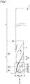
Fig. 1 is a first side view of a drill according to an embodiment when viewed in a first direction. -
Fig. 2 is a second side view of the drill according to the embodiment when viewed in a direction different from the first direction by 90°. -
Fig. 3 is a bottom view of the drill according to the embodiment. -
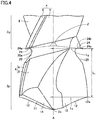
Fig. 4 is a partial enlarged side view of a region IV shown inFig. 1 in the drill according to the embodiment. -
Fig. 5 is a partial enlarged view of the drill according to the embodiment. -
Fig. 6 is a diagram showing a photomicrograph of an opening of a through hole when the through hole is formed in a layered body using a drill of an Example 1. -
Fig. 7 is a diagram showing a photomicrograph of an opening of a through hole when the through hole is formed in a layered body using a drill of a Comparative Example. - When perforating the layered body by moving the drill of Patent Literature 1 into the layered body from the FRP layer side toward the metal layer side, ring-shaped swarf may be generated in the metal layer. One embodiment of the present invention has been made to solve the foregoing problem, and has an object to provide a drill that can suppress ring-shaped swarf from being generated in a workpiece when perforating the workpiece.
- According to one embodiment of the present invention, ring-shaped swarf can be suppressed from being generated in a workpiece when perforating the workpiece.
- First, the following describes a summary of an embodiment of the present invention.
- (1) A drill 1 according to the present disclosure includes a
body 2 having afront end 2a and aback end 2b opposite tofront end 2a.Body 2 includes afirst cutting edge 12, a secondcutting edge 24 apart fromfirst cutting edge 12 to theback end 2b side relative tofirst cutting edge 12, an outerperipheral portion 4, and aflank face 11. Outerperipheral portion 4 is provided with: ahelical flute 8 extending along a center axis A ofbody 2; and arecess 20 that extends in a direction crossing center axis A and that traverses outerperipheral portion 4. Center axis A ofbody 2 extends fromfront end 2a to backend 2b.Recess 20 includes: afirst surface 20a continuous to outerperipheral portion 4 and extending from outerperipheral portion 4 toward center axis A; and asecond surface 20b continuous tofirst surface 20a and extending fromfirst surface 20a to thefront end 2a side ofbody 2. Firstcutting edge 12 is constituted of a first ridgeline formed byflank face 11 and a surface ofhelical flute 8. Secondcutting edge 24 is constituted of a second ridgeline formed byfirst surface 20a and the surface ofhelical flute 8. In a side view ofbody 2 in a first direction in which a distance L4 between center axis A ofbody 2 and a firstouter end 12a offirst cutting edge 12 is seen the longest, a secondouter end 24a ofsecond cutting edge 24 is located at the center axis A side relative to firstouter end 12a offirst cutting edge 12.
As such, in drill 1 of the present disclosure, the length ofsecond cutting edge 24 is short to such an extent that secondouter end 24a ofsecond cutting edge 24 is located at the center axis A side relative to firstouter end 12a of firstcutting edge 12 in the side view ofbody 2 in the first direction. Accordingly, ring-shaped swarf generated when perforating a workpiece byfirst cutting edge 12 is cut by secondcutting edge 24, and is removed from the workpiece. With drill 1 according to the present disclosure, ring-shaped swarf can be suppressed from being generated in the workpiece when perforating the workpiece. - (2) In drill 1 according to (1), in a plan view of
front end 2a in a second direction along center axis A, a second distance r2 is longer than a first distance r1 and a third distance r3. First distance r1 is a distance between firstouter end 12a of firstcutting edge 12 and center axis A in the plan view. Second distance r2 is a distance between secondouter end 24a of secondcutting edge 24 and center axis A in the plan view. Third distance r3 is a distance between aninner end 24b of secondcutting edge 24 and center axis A in the plan view.
When rotating drill 1 around center axis A to perforate the workpiece, the path taken by secondcutting edge 24 overlaps with the path taken by firstouter end 12a of firstcutting edge 12 in the plan view offront end 2a in the second direction along center axis A. Accordingly, ring-shaped swarf generated when perforating a workpiece byfirst cutting edge 12 is more securely cut by secondcutting edge 24, and is more securely removed from the workpiece. With drill 1 according to the present disclosure, ring-shaped swarf can be suppressed from being generated in the workpiece when perforating the workpiece. - (3) In drill 1 according to (2),
second surface 20b is recessed toward center axis A. A distance L3 betweeninner end 24b ofsecond cutting edge 24 and a bottom portion 20c ofsecond surface 20b is more than or equal to 1% and less than or equal to 10% of a drill diameter D. Bottom portion 20c ofsecond surface 20b is a portion ofsecond surface 20b with a minimum distance from center axis A. Drill diameter D is twice as large as second distance r2. Since distance L3 betweeninner end 24b of secondcutting edge 24 and bottom portion 20c ofsecond surface 20b is more than or equal to 1% of drill diameter D, ring-shaped swarf cut bysecond cutting edge 24 is released viarecess 20. The ring-shaped swarf cut by secondcutting edge 24 can be prevented from adhering to secondcutting edge 24. Ring-shaped swarf can be suppressed from being generated in the workpiece when perforating the workpiece. Since distance L3 betweeninner end 24b of secondcutting edge 24 and bottom portion 20c ofsecond surface 20b is less than or equal to 10% of drill diameter D, the mechanical strength of drill 1 is prevented from being excessively decreased, whereby drill 1 is less likely to be damaged during processing of the workpiece. - (4) In drill 1 according to any one of (1) to (3), a length L2 of
second cutting edge 24 is more than or equal to 0.15 mm and less than or equal to 0.35 mm. Since length L2 ofsecond cutting edge 24 is more than or equal to 0.15 mm, ring-shaped swarf generated when perforating a workpiece byfirst cutting edge 12 is more securely cut bysecond cutting edge 24, and is more securely removed from the workpiece. Since length L2 ofsecond cutting edge 24 is less than or equal to 0.35 mm, ring-shaped swarf can be prevented from being generated in the workpiece due to adhesion, tosecond cutting edge 24, of not only ring-shaped swarf having been already generated by firstcutting edge 12 but also swarf of the workpiece newly cut by secondcutting edge 24. - (5) In drill 1 according to any one of (1) to (4), a point angle (second point angle θ) of
second cutting edge 24 is more than or equal to 170° and less than or equal to 190°. Since the point angle (second point angle θ) of secondcutting edge 24 is more than or equal to 170°, ring-shaped swarf resulting from plastic deformation of the workpiece can be suppressed from being generated. Since the point angle (second point angle θ) ofsecond cutting edge 24 is less than or equal to 190°,second cutting edge 24 is suppressed from being decreased in mechanical strength, whereby secondcutting edge 24 can be prevented from being damaged during processing of the workpiece. - (6) In drill 1 according to any one of (1) to (5), a distance L1 between first
outer end 12a and secondouter end 24a in a direction in which center axis A extends is more than or equal to 1.0 mm and less than or equal to 3.0 mm. Since this distance L1 is less than or equal to 3.0 mm, ring-shaped swarf generated when perforating the workpiece usingfirst cutting edge 12 can be prevented from adhering tosecond cutting edge 24. Since distance L1 is more than or equal to 1.0 mm,second surface 20b recessed toward center axis A can be formed, thus facilitating removal of the ring-shaped swarf. Moreover,second cutting edge 24 can be readily formed nearfirst cutting edge 12 without excessively decreasing the mechanical strength offront end 2a ofbody 2. - (7) In drill 1 according to any one of (1) to (6), a helix angle α of
helical flute 8 is more than or equal to 20° and less than or equal to 40°. - (8) In drill 1 according to any one of (1) to (7),
first cutting edge 12 is a single-angle type. - The following describes an embodiment of the present disclosure with reference to figures. It should be noted that in the below-described figures, the same or corresponding portions in the figures are given the same reference characters and are not described repeatedly.
- With reference to
Fig. 1 to Fig. 5 , a configuration of a drill 1 according to the embodiment will be described. Drill 1 is used to perforate a workpiece, for example. The workpiece is a layered body in which a fiber reinforced plastic (FRP) layer, such as a carbon fiber reinforced plastic (CFRP) layer or a glass fiber reinforced plastic (GFRP) layer, and a metal layer are layered, for example. - As shown in
Fig. 1 andFig. 2 , drill 1 includes abody 2 and ashank 3.Body 2 includes afront end 2a and aback end 2b opposite tofront end 2a.Body 2 is composed of cemented carbide, for example. A diamond coating may be provided on a surface ofbody 2.Shank 3 is provided onback end 2b ofbody 2.Shank 3 is a grip to be held by a machine tool during use. -
Body 2 has a center axis A. Center axis A is an axis serving as the center of rotation of drill 1. Center axis A ofbody 2 extends fromfront end 2a toback end 2b.Body 2 includes an outerperipheral portion 4. Outerperipheral portion 4 includes an outerperipheral surface 5, which is an outer peripheral side surface ofbody 2. Outerperipheral portion 4 may further include amargin 6.Margin 6 is provided at a leading edge (front edge portion of outerperipheral portion 4 in a rotation direction C of drill 1 (seeFig. 3 )) of outerperipheral portion 4, and protrudes from outerperipheral surface 5.Margin 6 forms a space between the workpiece and outerperipheral surface 5 of afirst portion 2p during processing of the workpiece so as to prevent outerperipheral surface 5 from coming into contact with the workpiece. - Outer
peripheral portion 4 is provided with ahelical flute 8 extending along center axis A ofbody 2.Helical flute 8 is formed to extend fromfront end 2a to a vicinity ofback end 2b.Helical flute 8 is formed in the form of a helix around center axis A. Swarf cut out from the workpiece during processing of the workpiece is released viahelical flute 8. A plurality ofhelical flutes 8 may be formed. A helix angle α ofhelical flute 8 may be more than or equal to 10°, or may be more than or equal to 20°, for example. Helix angle α ofhelical flute 8 may be less than or equal to 40°, or may be less than or equal to 30°, for example. As shown inFig. 1 , helix angle α ofhelical flute 8 is an angle between center axis A and the extending direction ofhelical flute 8. -
Body 2 includesfirst portion 2p and asecond portion 2q, and is provided with arecess 20 betweenfirst portion 2p andsecond portion 2q.First portion 2p includesfront end 2a ofbody 2.Second portion 2q includesback end 2b ofbody 2. The diameter ofsecond portion 2q becomes gradually larger from therecess 20 side ofsecond portion 2q toward theback end 2b side ofsecond portion 2q.Recess 20 is recessed from outerperipheral portion 4 toward centeraxis A. Recess 20 is formed by polishing outerperipheral portion 4 using a grindstone, for example. - As shown in
Fig. 1 to Fig. 4 ,first portion 2p includes afirst cutting edge 12, aflank face 11, arake face 10, and outerperipheral portion 4.Helical flute 8 extends also tofirst portion 2p. First cuttingedge 12 is constituted of first ridgelines formed byflank face 11 and the surface ofhelical flute 8. A portion of the surface ofhelical flute 8 constitutesrake face 10. First cuttingedge 12 includes a firstouter end 12a, which is a distal end offirst cutting edge 12 relative to center axis A.First cutting edge 12 is a single-angle type. First cuttingedge 12 may be a double-angle type including a first cutting edge portion and a second cutting edge portion, which have point angles different from each other. First cuttingedge 12 may be a triple-angle type including a first cutting edge portion, a second cutting edge portion, and a third cutting edge portion, which have point angles different from one another. -
First portion 2p may further include aback surface 14,front end ridgelines 15, and a thinningportion 17. Back surface 14 is continuous toflank face 11, and is located in a direction opposite to rotation direction C of drill 1 relative toflank face 11.Front end ridgeline 15 is a ridgeline formed byflank face 11 and backsurface 14. A first point angle offirst portion 2p may be more than or equal to 90°, or may be more than or equal to 110°. The first point angle offirst portion 2p may be less than or equal to 160°, or may be less than or equal to 140°. In the present embodiment, the first point angle offirst portion 2p is defined as an angle between front end ridgelines 15 in a side view of drill 1 in a direction perpendicular to the extending direction offront end ridgeline 15 and the extending direction of center axisA. Thinning portion 17 serves to decrease cutting resistance of drill 1 during processing of the workpiece. - As shown in
Fig. 1 to Fig. 4 ,recess 20 extends in a direction crossing centeraxis A. Recess 20 traverses outerperipheral portion 4.Body 2 is narrowed atrecess 20, andrecess 20 is a narrowed portion ofbody 2. An angle between center axis A and the extending direction ofrecess 20 is more than or equal to 80° and less than or equal to 100°, for example.Recess 20 is shallower thanhelical flute 8.Recess 20 includes: afirst surface 20a continuous to outerperipheral portion 4 and extending from outerperipheral portion 4 toward center axis A; and asecond surface 20b continuous tofirst surface 20a and extending fromfirst surface 20a toward thefront end 2a side ofbody 2.First surface 20a may be a flat surface.Second surface 20b may be a curved surface recessed fromfirst surface 20a toward center axis A. - As shown in
Fig. 1 to Fig. 4 ,body 2 includes asecond cutting edge 24 apart fromfirst cutting edge 12 to theback end 2b side relative tofirst cutting edge 12.Second cutting edge 24 is constituted of second ridgelines that are formed by the surface ofhelical flute 8 andfirst surface 20a ofrecess 20 and that are adjacent to the leading edge of outerperipheral portion 4.Second cutting edge 24 includes: a secondouter end 24a, which is a distal end ofsecond cutting edge 24 relative to center axis A; and aninner end 24b, which is a proximal edge ofsecond cutting edge 24 relative to center axis A.Second surface 20b is continuous toinner end 24b ofsecond cutting edge 24.Second surface 20b is recessed frominner end 24b ofsecond cutting edge 24 toward center axis A. - As shown in
Fig. 1 andFig. 4 , in a side view ofbody 2 in a first direction in which a distance L4 between center axis A ofbody 2 and firstouter end 12a offirst cutting edge 12 is seen the longest, secondouter end 24a ofsecond cutting edge 24 is located at the center axis A side relative to firstouter end 12a offirst cutting edge 12. In other words, in the side view ofbody 2 in the first direction, distance L5 between secondouter end 24a ofsecond cutting edge 24 and center axis A is smaller than a distance L4 between firstouter end 12a offirst cutting edge 12 and center axis A. - A length L2 of
second cutting edge 24 may be less than or equal to 0.35 mm, or may be less than or equal to 0.25 mm. Length L2 ofsecond cutting edge 24 is defined as a length between secondouter end 24a andinner end 24b ofsecond cutting edge 24. Since length L2 ofsecond cutting edge 24 is less than or equal to 0.35 mm, ring-shaped swarf can be prevented from being generated due to adhesion, tosecond cutting edge 24, of not only ring-shaped swarf having been already generated byfirst cutting edge 12 but also swarf of the workpiece newly cut bysecond cutting edge 24. Length L2 ofsecond cutting edge 24 may be more than or equal to 0.15 mm. Since length L2 ofsecond cutting edge 24 is more than or equal to 0.15 mm, ring-shaped swarf generated when perforating the workpiece by first cuttingedge 12 is more securely cut bysecond cutting edge 24, and is more securely removed from the workpiece. - As shown in
Fig. 3 , in a plan view offront end 2a in a second direction along center axis A, a second distance r2 is longer than a first distance r1 and a third distance r3. First distance r1 is a distance between firstouter end 12a offirst cutting edge 12 and center axis A in the plan view offront end 2a in the second direction along center axis A. Second distance r2 is a distance between secondouter end 24a ofsecond cutting edge 24 and center axis A in the plan view offront end 2a in the second direction along center axis A. Third distance r3 is a distance betweeninner end 24b ofsecond cutting edge 24 and center axis A in the plan view offront end 2a in the second direction along center axis A. - As shown in
Fig. 3 andFig. 5 , when drill 1 is rotated around center axis A to perforate the workpiece, a path taken bysecond cutting edge 24 overlaps with a path taken by firstouter end 12a of first cutting edge 12 (aline 12p obtained by extending the path taken by firstouter end 12a offirst cutting edge 12 in parallel with center axis A) in the plan view offront end 2a in the second direction along center axis A. Hence, ring-shaped swarf generated when perforating the workpiece using first cutting edge 12 (for example, ring-shaped swarf generated in the metal layer of the layered body in which the CFRP layer and the metal layer are layered) is securely cut bysecond cutting edge 24 and is securely removed from the workpiece. - As shown in
Fig. 4 , a second point angle θ ofsecond cutting edge 24 is more than or equal to 170° and less than or equal to 190°. Since second point angle θ ofsecond cutting edge 24 is more than or equal to 170°, it is possible to suppress generation of ring-shaped swarf resulting from plastic deformation of the workpiece (for example, ring-shaped swarf generated in the metal layer due to plastic deformation of the metal layer in the layered body in which the CFRP layer and the metal layer are layered). Since second point angle θ ofsecond cutting edge 24 is less than or equal to 190°,second cutting edge 24 is suppressed from being decreased in mechanical strength, wherebysecond cutting edge 24 can be prevented from being damaged during processing of the workpiece. - As shown in
Fig. 5 , a distance L3 betweeninner end 24b ofsecond cutting edge 24 and bottom portion 20c ofsecond surface 20b is more than or equal to 1% and less than or equal to 10% of a drill diameter D. Bottom portion 20c ofsecond surface 20b is a portion of the surface ofsecond surface 20b with the minimum distance from center axis A. Distance L3 betweeninner end 24b ofsecond cutting edge 24 and bottom portion 20c ofsecond surface 20b represents a depth of the recess ofsecond surface 20b. - In the present specification, distance L3 between
inner end 24b ofsecond cutting edge 24 and bottom portion 20c ofsecond surface 20b means a distance betweeninner end 24b ofsecond cutting edge 24 and bottom portion 20c ofsecond surface 20b in a plan view in a third direction. The third direction is a direction in which the distance betweeninner end 24b ofsecond cutting edge 24 and bottom portion 20c ofsecond surface 20b in the direction frominner end 24b ofsecond cutting edge 24 toward center axis A is seen the longest in the side view of drill 1 (body 2) in the direction in which the distance betweeninner end 24b ofsecond cutting edge 24 and bottom portion 20c ofsecond surface 20b is seen the longest. As shown inFig. 3 , drill diameter D is twice as large as second distance r2. In the present specification, drill diameter D is a distance between secondouter end 24a of onesecond cutting edge 24 and secondouter end 24a of the othersecond cutting edge 24. - Since distance L3 between
inner end 24b ofsecond cutting edge 24 and bottom portion 20c ofsecond surface 20b is more than or equal to 1% of drill diameter D, the ring-shaped swarf cut bysecond cutting edge 24 is released viarecess 20. The ring-shaped swarf cut bysecond cutting edge 24 can be prevented from adhering tosecond cutting edge 24. Since distance L3 betweeninner end 24b ofsecond cutting edge 24 and bottom portion 20c ofsecond surface 20b is less than or equal to 10% of drill diameter D, the mechanical strength of drill 1 is prevented from being excessively decreased, whereby drill 1 is less likely to be damaged readily. - In a ridgeline formed by the surface of
helical flute 8 andsecond surface 20b in the plan view in the third direction, bottom portion 20c ofsecond surface 20b is located at a central region or a region at theinner end 24b side ofsecond cutting edge 24 among three regions obtained by equally dividing this ridgeline into three. - As shown in
Fig. 4 , a distance L1 between firstouter end 12a and secondouter end 24a in the direction in which center axis A extends is more than or equal to 1.0 mm and less than or equal to 3.0 mm. Since this distance L1 is less than or equal to 3.0 mm, ring-shaped swarf generated when perforating the workpiece usingfirst cutting edge 12 can be prevented from adhering tosecond cutting edge 24. Since distance L1 is more than or equal to 1.0 mm,second surface 20b recessed toward center axis A can be formed, thus facilitating removal of the ring-shaped swarf. Moreover,second cutting edge 24 can be readily formed nearfirst cutting edge 12 without excessively decreasing the mechanical strength offirst portion 2p ofbody 2. - Drills of Examples 1 to 5 and a drill of a Comparative Example were prepared. In each of the drills of Examples 1 to 5 and the drill of the Comparative Example, length L2 of
second cutting edge 24, second point angle θ ofsecond cutting edge 24, distance L1 between firstouter end 12a and secondouter end 24a, and helix angle α ofhelical flute 8 are as being shown in Table 1. In each of the drills of Examples 1 to 5, in the side view ofbody 2 in the first direction in which distance L4 between center axis A ofbody 2 and firstouter end 12a offirst cutting edge 12 is seen the longest, secondouter end 24a ofsecond cutting edge 24 is located at the center axis A side relative to firstouter end 12a offirst cutting edge 12. On the other hand, in the drill of the Comparative Example, in the side view ofbody 2 in the first direction, secondouter end 24a ofsecond cutting edge 24 is opposite to center axis A relative to firstouter end 12a offirst cutting edge 12. In each of the drills of Examples 1 to 5 and the drill of the Comparative Example,body 2 is composed of cemented carbide and a diamond coating is provided on a surface ofbody 2. It should be noted that in each of the drills of Examples 1 to 5 and the drill of the Comparative Example, the first point angle is 130° and drill diameter D is 4.8 mm.[Table 1] L2 (mm) θ (°) L1 (mm) α (°) Ring-Shaped Swarf Example 1 0.2 180 3.0 30 Not Generated Example 2 0.1 180 2.5 40 Not Generated Example 3 0.3 150 2.0 30 Not Generated Example 4 0.2 170 2.0 40 Not Generated Example 5 0.3 200 3.0 30 Not Generated Comparative Example 0.4 180 1.0 25 Generated - Each of the drills of Examples 1 to 5 and the drill of the Comparative Example was used to perforate a workpiece. The workpiece is a layered body in which a CFRP plate having a thickness of 5.0 mm and an aluminum plate having a thickness of 5.0 mm are layered. Each of the drills of Examples 1 to 5 and the drill of the Comparative Example was moved into the layered body from the CFRP plate side toward the aluminum plate so as to perforate the layered body, and it was observed whether or not ring-shaped swarf was generated in the metal layer.
- As shown in
Fig. 6 , when the layered body was perforated using the drill of Example 1, no ring-shaped swarf was generated in the metal layer. Likewise, when the layered body was perforated using each of the drills of Examples 2 to 5, no ring-shaped swarf was generated in the metal layer. On the other hand, as shown inFig. 7 , when the layered body was perforated using the drill of the Comparative Example, ring-shaped swarf was generated in the metal layer. - The embodiments disclosed herein are illustrative and non-restrictive in any respect. The scope of the present invention is defined by the terms of the claims, rather than the embodiments described above, and is intended to include any modifications within the scope and meaning equivalent to the terms of the claims.
- 1: drill; 2: body; 2a: front end; 2b: back end; 2p: first portion; 2q: second portion; 3: shank; 4: outer peripheral portion; 5: outer peripheral surface; 6: margin; 8: helical flute; 10: rake face; 11: flank face; 12: first cutting edge; 12a: first outer end; 12p: line obtained by extending a path taken by the first outer end in parallel with the center axis; 14: back surface; 15: front end ridgeline; 17: thinning portion; 20: recess; 20a: first surface; 20b: second surface; 20c: bottom portion; 24: second cutting edge; 24a: second outer end; 24b: inner end; A: center axis; C: rotation direction; D: drill diameter.
Claims (8)
- A drill comprising a body having a front end and a back end opposite to the front end, wherein
the body includes a first cutting edge, a second cutting edge apart from the first cutting edge to the back end side relative to the first cutting edge, an outer peripheral portion, and a flank face,
the outer peripheral portion being provided witha helical flute extending along a center axis of the body, anda recess extending in a direction crossing the center axis and traversing the outer peripheral portion, the center axis of the body extending from the front end to the back end,the recess includesa first surface continuous to the outer peripheral portion and extending from the outer peripheral portion toward the center axis, anda second surface continuous to the first surface and extending from the first surface to the front end side of the body,the first cutting edge is constituted of a first ridgeline formed by the flank face and a surface of the helical flute,
the second cutting edge is constituted of a second ridgeline formed by the first surface and the surface of the helical flute, and
in a side view of the body in a first direction in which a distance between the center axis of the body and a first outer end of the first cutting edge is seen the longest, a second outer end of the second cutting edge is located at the center axis side relative to the first outer end of the first cutting edge. - The drill according to claim 1, wherein
in a plan view of the front end in a second direction along the center axis, a second distance is longer than a first distance and a third distance,
the first distance is a distance between the first outer end of the first cutting edge and the center axis in the plan view,
the second distance is a distance between the second outer end of the second cutting edge and the center axis in the plan view, and
the third distance is a distance between an inner end of the second cutting edge and the center axis in the plan view. - The drill according to claim 2, wherein
the second surface is recessed toward the center axis,
a distance between the inner end of the second cutting edge and a bottom portion of the second surface is more than or equal to 1% and less than or equal to 10% of a drill diameter,
the bottom portion of the second surface is a portion of the second surface with a minimum distance from the center axis, and
the drill diameter is twice as large as the second distance. - The drill according to any one of claims 1 to 3, wherein a length of the second cutting edge is more than or equal to 0.15 mm and less than or equal to 0.35 mm.
- The drill according to any one of claims 1 to 4, wherein a point angle of the second cutting edge is more than or equal to 170° and less than or equal to 190°.
- The drill according to any one of claims 1 to 5, wherein a distance between the first outer end and the second outer end in a direction in which the center axis extends is more than or equal to 1.0 mm and less than or equal to 3.0 mm.
- The drill according to any one of claims 1 to 6, wherein a helix angle of the helical flute is more than or equal to 20° and less than or equal to 40°.
- The drill according to any one of claims 1 to 7, wherein the first cutting edge is a single-angle type.
Applications Claiming Priority (1)
| Application Number | Priority Date | Filing Date | Title |
|---|---|---|---|
| PCT/JP2018/029595 WO2020031259A1 (en) | 2018-08-07 | 2018-08-07 | Drill |
Publications (2)
| Publication Number | Publication Date |
|---|---|
| EP3636370A1 true EP3636370A1 (en) | 2020-04-15 |
| EP3636370A4 EP3636370A4 (en) | 2020-09-09 |
Family
ID=69415199
Family Applications (1)
| Application Number | Title | Priority Date | Filing Date |
|---|---|---|---|
| EP18880079.1A Pending EP3636370A4 (en) | 2018-08-07 | 2018-08-07 | Drill |
Country Status (6)
| Country | Link |
|---|---|
| US (1) | US11229959B2 (en) |
| EP (1) | EP3636370A4 (en) |
| JP (1) | JP6729853B2 (en) |
| KR (1) | KR102150220B1 (en) |
| CN (1) | CN111010869B (en) |
| WO (1) | WO2020031259A1 (en) |
Families Citing this family (4)
| Publication number | Priority date | Publication date | Assignee | Title |
|---|---|---|---|---|
| US11007583B2 (en) | 2016-02-14 | 2021-05-18 | Hongjia Wang | Twist drill |
| DE102019135404A1 (en) | 2019-12-20 | 2021-06-24 | Gühring KG | Twist drill with a stepped cutting tip |
| DE102020214134A1 (en) * | 2020-11-10 | 2022-05-12 | MAPAL Fabrik für Präzisionswerkzeuge Dr. Kress KG | Tool |
| USD1092579S1 (en) * | 2023-02-01 | 2025-09-09 | Sumitomo Electric Hardmetal Corp. | Cutting tool |
Family Cites Families (40)
| Publication number | Priority date | Publication date | Assignee | Title |
|---|---|---|---|---|
| US1384733A (en) * | 1921-07-12 | Twlst-dkill | ||
| US750537A (en) * | 1904-01-26 | Drilling-tool | ||
| US867639A (en) * | 1906-05-21 | 1907-10-08 | George J Bragg | Twist-drill. |
| US1000067A (en) | 1911-03-16 | 1911-08-08 | Paul C Seegmueller | Drill. |
| US2322894A (en) * | 1939-06-29 | 1943-06-29 | Rustless Iron & Steel Corp | Twist drill |
| US2332295A (en) * | 1941-11-07 | 1943-10-19 | Western Electric Co | Drill |
| US2646701A (en) * | 1949-12-27 | 1953-07-28 | Peter A Letien | Stepped edge cutting tool |
| US3667857A (en) * | 1970-10-30 | 1972-06-06 | Nat Twist Drill & Tool Co | Combined drill and reamer construction |
| US3786713A (en) * | 1971-10-15 | 1974-01-22 | Illinois Tool Works | Chip breaker drill screw |
| US3913196A (en) * | 1974-08-29 | 1975-10-21 | Lear Siegler Inc | Rotary cutting tool |
| JPS5511897U (en) * | 1978-07-11 | 1980-01-25 | ||
| JPS6045607U (en) * | 1983-09-03 | 1985-03-30 | 株式会社 協和工機 | stepped drill |
| DE3730378A1 (en) * | 1987-09-10 | 1989-03-23 | Micro Crystal Ag | CUTTING TOOL, ESPECIALLY DRILLING AND / OR MILLING |
| JPH0621604Y2 (en) * | 1987-09-18 | 1994-06-08 | 三菱マテリアル株式会社 | Step drill |
| JP2678016B2 (en) * | 1988-06-07 | 1997-11-17 | 菱高精機株式会社 | Reamer with tip blade |
| DE8912860U1 (en) * | 1989-10-31 | 1990-02-01 | Hertel AG Werkzeuge + Hartstoffe, 8510 Fürth | Twist drill |
| DE4231381A1 (en) * | 1992-09-19 | 1994-03-24 | Mitsubishi Materials Corp | drill |
| JP3662684B2 (en) * | 1996-09-05 | 2005-06-22 | カヤバ工業株式会社 | Cutting tools |
| US6126367A (en) * | 1998-03-31 | 2000-10-03 | Reed; Gary Jack | Precision drill bit |
| US7575401B1 (en) * | 2004-11-18 | 2009-08-18 | Precorp, Inc. | PCD drill for composite materials |
| DE102005014422B4 (en) * | 2005-03-24 | 2019-10-24 | EMUGE-Werk Richard Glimpel GmbH & Co. KG Fabrik für Präzisionswerkzeuge | Drill |
| JP2008000836A (en) | 2006-06-21 | 2008-01-10 | Sumitomo Electric Hardmetal Corp | Drill |
| US7665935B1 (en) * | 2006-07-27 | 2010-02-23 | Precorp, Inc. | Carbide drill bit for composite materials |
| US8714890B2 (en) * | 2007-02-09 | 2014-05-06 | The Boeing Company | Cutter for drilling and reaming |
| SE531188C2 (en) * | 2007-05-29 | 2009-01-13 | Sandvik Intellectual Property | Drill body for chip separating machining |
| JP5184902B2 (en) * | 2008-01-23 | 2013-04-17 | 住友電気工業株式会社 | Drilling tools and drilling methods for fiber reinforced composites |
| SE533679C2 (en) * | 2009-04-07 | 2010-11-30 | Sandvik Intellectual Property | Solid step drill |
| JP5675524B2 (en) * | 2011-07-26 | 2015-02-25 | 本田技研工業株式会社 | Cutting tool |
| KR20130032671A (en) * | 2011-09-23 | 2013-04-02 | 대구텍 유한회사 | Drilling tool for composite material |
| US9308589B2 (en) * | 2011-12-27 | 2016-04-12 | Sumitomo Electric Industries, Ltd. | Drill |
| DE102012012479A1 (en) * | 2012-03-26 | 2013-09-26 | MAPAL Fabrik für Präzisionswerkzeuge Dr. Kress KG | drill |
| JP2014037008A (en) * | 2012-08-10 | 2014-02-27 | Tochigi Prefecture | Boring drill |
| US9555484B2 (en) * | 2012-12-28 | 2017-01-31 | Kyocera Corporation | Drill and method of producing machined product using the same |
| JP6606840B2 (en) * | 2014-03-28 | 2019-11-20 | 三菱マテリアル株式会社 | Rotary cutting tool with polycrystalline diamond sintered body |
| JP6589506B2 (en) * | 2014-09-26 | 2019-10-16 | 三菱マテリアル株式会社 | Drill and drill head |
| JP6247807B2 (en) * | 2014-12-12 | 2017-12-13 | 株式会社 東陽 | Cutting tool and cutting apparatus equipped with this cutting tool |
| CN104772505A (en) * | 2015-03-27 | 2015-07-15 | 镇江锐诚精密工具有限公司 | Anti-blocking drill bit structure |
| WO2016158463A1 (en) * | 2015-03-30 | 2016-10-06 | 三菱日立ツール株式会社 | Drill |
| US10315257B2 (en) * | 2015-05-28 | 2019-06-11 | Kyocera Corporation | Drill and method of manufacturing machined product |
| WO2017208939A1 (en) | 2016-05-31 | 2017-12-07 | 三菱重工業株式会社 | Cutting tool |
-
2018
- 2018-08-07 EP EP18880079.1A patent/EP3636370A4/en active Pending
- 2018-08-07 KR KR1020197017757A patent/KR102150220B1/en active Active
- 2018-08-07 JP JP2019520465A patent/JP6729853B2/en active Active
- 2018-08-07 US US16/473,397 patent/US11229959B2/en active Active
- 2018-08-07 WO PCT/JP2018/029595 patent/WO2020031259A1/en not_active Ceased
- 2018-08-07 CN CN201880005542.4A patent/CN111010869B/en active Active
Also Published As
| Publication number | Publication date |
|---|---|
| US20200406375A1 (en) | 2020-12-31 |
| KR102150220B1 (en) | 2020-08-31 |
| CN111010869A (en) | 2020-04-14 |
| US11229959B2 (en) | 2022-01-25 |
| CN111010869B (en) | 2020-12-18 |
| JPWO2020031259A1 (en) | 2020-08-20 |
| WO2020031259A1 (en) | 2020-02-13 |
| JP6729853B2 (en) | 2020-07-29 |
| EP3636370A4 (en) | 2020-09-09 |
| KR20200017378A (en) | 2020-02-18 |
Similar Documents
| Publication | Publication Date | Title |
|---|---|---|
| JP5568006B2 (en) | End mill for orbital drilling of fiber reinforced plastic materials | |
| US10220451B2 (en) | End mill and method for manufacturing machined product | |
| US11229959B2 (en) | Drill | |
| JP5475808B2 (en) | Rotating tools and cutting inserts for cutting | |
| EP2554309A1 (en) | Endmill | |
| EP2233234B1 (en) | End mill | |
| US10259050B2 (en) | Drill and method of manufacturing machined product using the same | |
| EP3278913A1 (en) | Formed end mill | |
| JP2017056552A (en) | Cutting insert and blade-exchange type cutting tool | |
| EP3205431A1 (en) | Radius end mill | |
| US12186814B2 (en) | Milling tool for milling workpieces | |
| JP2009172708A (en) | Drilling tools and drilling methods for fiber reinforced composites | |
| US12220754B2 (en) | Rotary cutting tool with continuous major flutes and discontinuous minor flutes intersecting to form quadrilateral-shaped face portions | |
| JP2012223882A (en) | Drilling tool and drilling method of fiber-reinforced composite material | |
| CN107073597A (en) | The manufacture method of the machining thing of drill bit and the use drill bit | |
| US11351617B2 (en) | Rotating tool | |
| JP6255925B2 (en) | drill | |
| JP2014193513A (en) | Drill | |
| US20200070260A1 (en) | Cutting Tool and Cutting Method | |
| US10981235B2 (en) | Rotary cutting tool and method of manufacturing the same | |
| EP4066972B1 (en) | Rotary cutting tool | |
| CN107414159A (en) | A kind of slotting cutter of processing high-hardness material | |
| JP2019136847A (en) | drill | |
| JP2018043321A (en) | Cutting insert and cutting edge exchangeable cutting tool | |
| JP2018083245A (en) | 2-flute ball end mill |
Legal Events
| Date | Code | Title | Description |
|---|---|---|---|
| STAA | Information on the status of an ep patent application or granted ep patent |
Free format text: STATUS: UNKNOWN |
|
| STAA | Information on the status of an ep patent application or granted ep patent |
Free format text: STATUS: THE INTERNATIONAL PUBLICATION HAS BEEN MADE |
|
| PUAI | Public reference made under article 153(3) epc to a published international application that has entered the european phase |
Free format text: ORIGINAL CODE: 0009012 |
|
| STAA | Information on the status of an ep patent application or granted ep patent |
Free format text: STATUS: REQUEST FOR EXAMINATION WAS MADE |
|
| 17P | Request for examination filed |
Effective date: 20190530 |
|
| AK | Designated contracting states |
Kind code of ref document: A1 Designated state(s): AL AT BE BG CH CY CZ DE DK EE ES FI FR GB GR HR HU IE IS IT LI LT LU LV MC MK MT NL NO PL PT RO RS SE SI SK SM TR |
|
| AX | Request for extension of the european patent |
Extension state: BA ME |
|
| R17P | Request for examination filed (corrected) |
Effective date: 20190530 |
|
| REG | Reference to a national code |
Ref country code: DE Ref legal event code: R079 Free format text: PREVIOUS MAIN CLASS: B23B0051000000 Ipc: B23B0051100000 |
|
| A4 | Supplementary search report drawn up and despatched |
Effective date: 20200810 |
|
| RIC1 | Information provided on ipc code assigned before grant |
Ipc: B23B 51/10 20060101AFI20200804BHEP Ipc: B23B 51/02 20060101ALI20200804BHEP |
|
| DAV | Request for validation of the european patent (deleted) | ||
| DAX | Request for extension of the european patent (deleted) | ||
| STAA | Information on the status of an ep patent application or granted ep patent |
Free format text: STATUS: EXAMINATION IS IN PROGRESS |
|
| 17Q | First examination report despatched |
Effective date: 20231116 |