EP3636317A1 - Phototherapeutic apparatus - Google Patents
Phototherapeutic apparatus Download PDFInfo
- Publication number
- EP3636317A1 EP3636317A1 EP18810824.5A EP18810824A EP3636317A1 EP 3636317 A1 EP3636317 A1 EP 3636317A1 EP 18810824 A EP18810824 A EP 18810824A EP 3636317 A1 EP3636317 A1 EP 3636317A1
- Authority
- EP
- European Patent Office
- Prior art keywords
- probe
- irradiation
- fixing unit
- observation
- phototherapy device
- Prior art date
- Legal status (The legal status is an assumption and is not a legal conclusion. Google has not performed a legal analysis and makes no representation as to the accuracy of the status listed.)
- Granted
Links
Images






Classifications
-
- A—HUMAN NECESSITIES
- A61—MEDICAL OR VETERINARY SCIENCE; HYGIENE
- A61N—ELECTROTHERAPY; MAGNETOTHERAPY; RADIATION THERAPY; ULTRASOUND THERAPY
- A61N5/00—Radiation therapy
- A61N5/06—Radiation therapy using light
- A61N5/0613—Apparatus adapted for a specific treatment
- A61N5/0622—Optical stimulation for exciting neural tissue
-
- A—HUMAN NECESSITIES
- A61—MEDICAL OR VETERINARY SCIENCE; HYGIENE
- A61N—ELECTROTHERAPY; MAGNETOTHERAPY; RADIATION THERAPY; ULTRASOUND THERAPY
- A61N5/00—Radiation therapy
- A61N5/06—Radiation therapy using light
- A61N5/067—Radiation therapy using light using laser light
-
- A—HUMAN NECESSITIES
- A61—MEDICAL OR VETERINARY SCIENCE; HYGIENE
- A61H—PHYSICAL THERAPY APPARATUS, e.g. DEVICES FOR LOCATING OR STIMULATING REFLEX POINTS IN THE BODY; ARTIFICIAL RESPIRATION; MASSAGE; BATHING DEVICES FOR SPECIAL THERAPEUTIC OR HYGIENIC PURPOSES OR SPECIFIC PARTS OF THE BODY
- A61H39/00—Devices for locating or stimulating specific reflex points of the body for physical therapy, e.g. acupuncture
- A61H2039/005—Devices for locating or stimulating specific reflex points of the body for physical therapy, e.g. acupuncture by means of electromagnetic waves, e.g. I.R., U.V. rays
-
- A—HUMAN NECESSITIES
- A61—MEDICAL OR VETERINARY SCIENCE; HYGIENE
- A61N—ELECTROTHERAPY; MAGNETOTHERAPY; RADIATION THERAPY; ULTRASOUND THERAPY
- A61N5/00—Radiation therapy
- A61N5/06—Radiation therapy using light
- A61N2005/0626—Monitoring, verifying, controlling systems and methods
-
- A—HUMAN NECESSITIES
- A61—MEDICAL OR VETERINARY SCIENCE; HYGIENE
- A61N—ELECTROTHERAPY; MAGNETOTHERAPY; RADIATION THERAPY; ULTRASOUND THERAPY
- A61N5/00—Radiation therapy
- A61N5/06—Radiation therapy using light
- A61N2005/0632—Constructional aspects of the apparatus
-
- A—HUMAN NECESSITIES
- A61—MEDICAL OR VETERINARY SCIENCE; HYGIENE
- A61N—ELECTROTHERAPY; MAGNETOTHERAPY; RADIATION THERAPY; ULTRASOUND THERAPY
- A61N5/00—Radiation therapy
- A61N5/06—Radiation therapy using light
- A61N2005/0632—Constructional aspects of the apparatus
- A61N2005/0633—Arrangements for lifting or hinging the frame which supports the light sources
-
- A—HUMAN NECESSITIES
- A61—MEDICAL OR VETERINARY SCIENCE; HYGIENE
- A61N—ELECTROTHERAPY; MAGNETOTHERAPY; RADIATION THERAPY; ULTRASOUND THERAPY
- A61N5/00—Radiation therapy
- A61N5/06—Radiation therapy using light
- A61N2005/0635—Radiation therapy using light characterised by the body area to be irradiated
- A61N2005/0643—Applicators, probes irradiating specific body areas in close proximity
- A61N2005/0645—Applicators worn by the patient
-
- A—HUMAN NECESSITIES
- A61—MEDICAL OR VETERINARY SCIENCE; HYGIENE
- A61N—ELECTROTHERAPY; MAGNETOTHERAPY; RADIATION THERAPY; ULTRASOUND THERAPY
- A61N5/00—Radiation therapy
- A61N5/06—Radiation therapy using light
- A61N5/0613—Apparatus adapted for a specific treatment
- A61N5/0619—Acupuncture
Definitions
- the present invention relates to a phototherapy device.
- Phototherapy devices have been used for treatment such as relief of aching pain by irradiating an affected area or an acupressure point, for example, with infrared light (approximate wavelengths of 700 nm to 2500 nm) as treatment light percutaneously. It has recently been revealed that irradiation of light has an action on various nerves, such as selective suppression of nerve conduction in sensory fibers that transmit pain in peripheral nervous system, suppression of pain-producing substances, relief of sympathicotonia and the like. These actions have been applied to improve and treat lower urinary tract symptoms (LUTS) by photoirradiation (PLT 1). Among lights, laser light is widely used in these applications since it can be radiated at a specific wavelength with high power.
- LUTS lower urinary tract symptoms
- PLT 2 proposes a configuration including image-taking means of taking an image of a site to be irradiated with laser light in addition to a laser light source means of radiating laser light into a photoirradiation probe. With this configuration, the image-taking means takes pictures to provide rough understanding of the state and the position of the affected area.
- the sacral foramina where bladder sensory nerves exist is aimed at and irradiated with light percutaneously in order to suppress abnormal activities of sensory nerves in the bladder. It is necessary to accurately aim at the sacral foramina for appropriate treatment.
- Photoirradiation is preferably performed by the patient himself/herself at home since photoirradiation for a few minutes to tens of minutes per day need to be repeated at a frequency of twice a week to every day.
- the physician locates the sacral foramina at hospital and places a marking indicating the irradiation position and the irradiation area on the skin just over the sacral foramina.
- the patient then performs photoirradiation at home with the help of the mark.
- the sacral foramina is positioned under the skin slightly below the lumbar region and in the back where the marking placed on the skin is out of sight of the patient. For this reason, positioning using imaging means such as a camera is necessary.
- Adjusting the irradiation probe to aim the irradiation position on the back and keeping the irradiation probe at the adjusted position force the patient to take a strained posture.
- using the method of positioning the irradiation probe relative to the marking on the patient with the camera equipped in the irradiation probe as disclosed in PLT 2 leads to increasing a burden on the patient.
- a probe fixing unit which inserts and fixes the irradiation probe toward the patient may be used to position the probe fixing unit appropriately relative to the patient's marking in advance.
- the irradiation probe may interfere with the camera when being inserted into the probe fixing unit. This problem is conspicuous particularly when the camera is disposed such that the optical axis of the camera is present coaxially relative to the optical axis of the light source of the irradiation probe fixed in the probe fixing unit in order to improve the positioning accuracy.
- An object of the present invention is therefore to provide a phototherapy device that enables photoirradiation accurately aiming at the sacral foramina and consequently provides appropriate treatment even when the treatment site is in the back which is out of sight of the patient, and the patient himself/herself performs photoirradiation at home, for example, as is the case of photoirradiation for LUTS patients.
- a phototherapy device of the present invention includes an irradiation probe for radiating irradiation light toward a living body, a probe fixing unit into which the irradiation probe is inserted and at the same time fixed on a living body, an observation module placed on the probe fixing unit and provided with an observation means for observing an irradiation site irradiated with irradiation light which is radiated toward the living body, and a moving means capable of moving the observation module to a space where the irradiation probe is to be placed/inserted in the probe fixing unit during observation of the irradiation site.
- this configuration enables photoirradiation accurately aiming at the sacral foramina and consequently provides appropriate treatment.
- the phototherapy device of the present embodiment is a device for performing LUTS treatment by irradiating the position of sacral foramina of the patient with light.
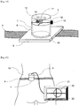
- Fig. 1 is a perspective view of the phototherapy device according to the present embodiment with an irradiation probe 2 inserted in a probe fixing unit 1.
- the phototherapy device includes the irradiation probe 2, the probe fixing unit 1, an observation module 3, and a fixing belt 4.
- the irradiation probe 2 is a member fixed to the probe fixing unit 1 for irradiating a predetermined irradiation site on the patient's skin with light.
- the irradiation probe 2 includes a probe cable 5 and a probe casing 6 and a treatment light source 7 is housed in the probe casing 6.
- the treatment light source 7 include a laser, an LED, a halogen lamp, or a xenon lamp.
- the treatment light source 7 is connected to a power supply for the treatment light source and a switch, which are not illustrated, through the probe cable 5, and the switch is operated to radiate light to the patient.
- the treatment light source 7 light may be externally guided into the probe casing 6 through a waveguide such as an optical fiber.
- the probe casing 6 is formed of, for example, plastic or metal in a hollow cylindrical shape.
- the shape of the probe casing 6 is not necessarily cylindrical.
- the probe fixing unit 1 includes a probe insertion part 8 and a patient contact part 9.
- the probe insertion part 8 is a member for fixing the irradiation probe 2 in the probe fixing unit 1 toward the patient by inserting the probe casing 6 therein.
- the patient contact part 9 is a member for fixing the probe fixing unit 1 to the patient's body surface to irradiate the irradiation site on the patient's body surface with light from the treatment light source 7 and is provided with a transmission window 10 at the center to allow irradiation light from the treatment light source 7 to pass through.
- the transmission window 10 is a hole provided in the patient contact part 9.
- the transmission window 10 is required only to allow irradiation light to pass through, and the patient contact part 9 may be partially formed of a material that transmits light, such as glass and plastic film.
- the observation module 3 includes a camera 11, an illumination light source 12, and a module casing 13.
- the camera 11 is a member for the patient to grasp the irradiation position and area of the photoirradiation site on the back.
- a CCD camera or a CMOS camera can be used.
- the image acquired by the camera 11 is displayed on an external monitor through wired or wireless communication.
- the illumination light source 12 is a member that illuminates the field of observation of the camera 11 to facilitate recognition of the irradiation position and the irradiation area by the camera 11.
- illumination light source 12 a laser, an LED, a halogen lamp, or a xenon lamp can be used.
- the module casing 13 is a member for holding the camera 11 and the illumination light source 12 and is equipped with an observation module power supply 14 inside for supplying electric power to the camera 11 and the illumination light source 12.
- observation module power supply 14 a primary battery or a secondary battery can be used. Alternatively, electric power may be externally supplied through a cable or the like.
- the observation module 3 and the probe fixing unit 1 are connected via a hinge 15.
- the hinge 15 is a member for moving the observation module 3 relative to the probe insertion part 8 and has one end fixed to the upper end (the end on the opposite side to the patient) of the probe insertion part 8 and the other end fixed to the outer periphery of the observation module 3.
- Fig. 2 is the arrangement of the observation module 3 and the probe fixing unit 1 when the irradiation probe 2 is not inserted.
- the observation module 3 has an outer diameter set to be equal to or greater than the outer diameter of the probe insertion part 8 and thus functions as the cap of the probe insertion part 8 in a state in which the irradiation probe 2 is not inserted and the hinge 15 is closed. In the state as in Fig.
- the observation module 3 is positioned on the top of the probe fixing unit 1, and the camera 11 in the observation module 3 is positioned such that the skin can be observed through the transmission window 10.
- This configuration enables the patient to visually recognize the marking at the back which is out of sight of the patient.
- the illumination light source 12 in the observation module 3 can illuminate the skin through the transmission window 10 to make the marking more visible. In this state, the observation module 3 and the camera 11 contained in the observation module 3 are at a position where they interfere with insertion of the irradiation probe 2.
- the observation module 3 can be moved to the position at which probe insertion is not hindered by opening the hinge 15 when the irradiation probe 2 is inserted into the probe insertion part 8.
- the observation module 3 and the probe fixing unit 1 are connected via the hinge 15.
- the connection part is not necessarily provided between the observation module 3 and the probe fixing unit 1 and they may be detachable from each other.
- the fixing belt 4 is a member for fixing the probe fixing unit 1 around the patient's body and attached to the probe fixing unit 1.
- Fig. 3 is a diagram illustrating the arrangement of an irradiation field 16 of the irradiation light when the irradiation probe 2 is inserted in the probe insertion part 8 and a field of observation 18 of the camera 11 when the irradiation probe 2 is not inserted and the patient skin 17 is observed using the observation module 3.
- the irradiation probe 2 and the observation module 3 are fixed such that the irradiation light and the field of observation 18 are arranged coaxially toward the patient skin 17.
- the treatment light source 7 and the camera 11 are thus arranged coaxially, so that the irradiation position and the irradiation area can be grasped accurately. Since the irradiation probe 2 is detachable from the probe fixing unit 1 and positioning can be performed by the lightweight probe fixing unit 1 alone, the patient can easily perform alignment and fixing by himself/herself even at the back.
- FIG. 4 A specific usage of the present phototherapy device is described with reference to Fig. 4 , Fig. 5, and Fig. 6 .
- Fig. 4 is a diagram illustrating a photoirradiation position of a patient.
- the patient's treatment site to be irradiated with light is specified under physician's diagnosis at a hospital or clinic.
- the position of sacral foramina to be irradiated with light in the patient's back 19 is located by palpation or X-ray fluoroscopy.
- a physician or any other healthcare worker then makes a marking 20 on the specified treatment site.
- ink or adhesive sheet can be used as the material of the marking 20.
- the marking 20 is preferably shaped so as to avoid the irradiation area.
- a hollow circular shape larger than the irradiation area may be employed, although embodiments are not limited thereto.
- the patient When the patient thereafter performs photoirradiation at home by himself/herself, the patient fixes the probe fixing unit 1 of the present photoirradiation device in alignment with the marking 20 made at a hospital or clinic.
- Fig. 5 is a diagram illustrating the method of placing the probe fixing unit 1 in alignment with the marking 20 on the patient.
- the patient first turns on the observation module power supply 14 of the observation module 3 and fixes the module at a predetermined position of the probe fixing unit 1 (in the present embodiment, the position with the hinge 15 closed).
- the probe fixing unit 1 is brought to the back, the state of the back is observed with the observation module 3 attached to the probe fixing unit 1, and then the marking 20 is recognized on a monitor 21.
- the probe fixing unit 1 is moved such that the marking 20 is at the center of a field of observation 18, and is positioned on the patient skin 17.
- a fixing belt 4 is wound around the body and the probe fixing unit 1 is fixed.
- the observation module 3 is removed from the probe fixing unit 1 and the irradiation probe 2 is inserted.
- the camera 11 when the camera 11 is placed in the probe fixing unit 1, the camera 11 is placed such that the marking 20 is captured by the camera 11 in the appropriately positioned state. If so, the irradiation probe 2 interferes with the camera 11 when being inserted into the probe fixing unit 1.
- the problem is conspicuous particularly when the camera 11 is arranged such that the optical axis of the camera 11 is present coaxially relative to the optical axis of the treatment light source 7 of the irradiation probe 2 fixed on the probe fixing unit 1 in order to improve the positioning accuracy.
- the observation module 3 can move between a first position at which it overlaps with the path of inserting the irradiation probe 2 and a second position at which it does not overlap with the path, so that the marking 20 can be observed from substantially the same position as the irradiation probe 2 is to be fixed, while the irradiation probe 2 does not interfere with the camera 11 when being inserted into the probe fixing unit 1. Accordingly, even when the treatment site is in the back which is out of sight of the patient, and the patient performs photoirradiation by himself/herself, for example, at home, the patient can easily perform alignment and fixing by himself/herself on the back. This configuration enables photoirradiation accurately aiming at the sacral foramina and consequently provides appropriate treatment. The configuration therefore can be widely utilized as a phototherapy device, for example, for LUTS patients.
- Fig. 7 and Fig. 8 are diagrams illustrating another embodiment of the present phototherapy device. Since there are many overlaps between the present embodiment and other embodiments, only the features characterizing the present embodiment will be described below and other descriptions of the configuration are omitted.
- the observation module 3 and the probe fixing unit 1 are connected via a rotation shaft 22 parallel to the direction of the center axis of the probe fixing unit 1.
- the rotation shaft 22 is a member for rotationally moving the observation module 3.
- the observation module 3 is positioned such that the patient skin 17 can be observed with the observation module 3 through the transmission window 10, and when the irradiation probe 2 is inserted in the probe insertion part 8, the observation module 3 can be easily moved with a smaller force to a position where it does not interfere with the probe insertion as illustrated in Fig. 7 .
- Fig. 9 and Fig. 10 are diagrams illustrating another embodiment of the present phototherapy device. Since there are many overlaps between the present embodiment and other embodiments, only the features characterizing the present embodiment will be described below and other descriptions of the configuration are omitted.
- the observation module 3 and the probe fixing unit 1 are connected via a rotation shaft 22 vertical to the direction of the center axis of the probe fixing unit 1.
- the observation module 3 includes a lever part 23 for rotating the observation module 3 in accordance with the movement of the irradiation probe 2 and an observation part 24 including a camera 11 and an illumination light source 12.
- the probe fixing unit 1 has a movement groove 25 for moving the observation part 24 to the outside of the probe insertion part 8 when the lever part 23 is pushed by the irradiation probe 2.
- this structure enables an arrangement such that the patient skin 17 can be observed with the observation part 24 through the transmission window 10.
- the irradiation probe 2 is inserted in the probe insertion part 8, as illustrated in Fig. 10 , the irradiation probe 2 pushes the lever part 23, so that the observation module 3 accordingly rotates around the rotation shaft 22 and moves out of the probe insertion part 8 through the movement groove 25.
- the observation module 3 can be easily moved to the position where the observation module 3 does not interfere with the insertion of the irradiation probe 2.
- Fig. 11 is a perspective view illustrating another embodiment of the present phototherapy device.
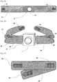
- Fig. 12 is a diagram illustrating a support casing 27 cut into halves in the present embodiment. Since there are many overlaps between the present embodiment and other embodiments, only the features characterizing the present embodiment will be described below and other descriptions of the configuration are omitted.
- the observation module 3 includes a camera 11, an illumination light source 12, and a rotational housing 26 and is placed inside the support casing 27 of the probe fixing unit 1.
- the rotational housing 26 further includes a rotation shaft 22 connecting the probe fixing unit 1 and the observation module 3, and a notch 28.
- the irradiation probe 2 is provided with a probe protrusion 29 to be fitted in the notch 28.
- Fig. 13 illustrates a state of the present embodiment when the irradiation probe 2 is not inserted.
- the camera 11 and the illumination light source 12 face the patient's skin 17 to enable the patient to grasp the irradiation position and the irradiation area and accurately fix the probe fixing unit 1 at an appropriate position.
- Fig. 14 illustrates a state of the present embodiment when the irradiation probe 2 is inserted.
- the probe protrusion 29 fits in the notch 28 and rotates the rotational housing 26 around the rotation shaft 22.
- Fig. 15 is a diagram illustrating the arrangement of irradiation light when the irradiation probe 2 is inserted in the probe insertion part 8 and the field of observation 18 of the camera 11 when the irradiation probe 2 is not inserted and the patient's skin 17 is observed with the observation module 3, in the present embodiment.
- the irradiation probe 2 and the observation module 3 are fixed such that the irradiation field 16 and the field of observation 18 are arranged coaxially toward the patient's skin 17. With such a configuration, the field of observation 18 can be moved only by inserting the irradiation probe 2.
- Fig. 16 is a perspective view illustrating another embodiment of the present phototherapy device. Since there are many overlaps between the present embodiment and other embodiments, only the features characterizing the present embodiment will be described below and other descriptions of the configuration are omitted.
- the observation module 3 is placed on a side surface of the probe fixing unit 1, and an observation mirror 30 is placed in the probe fixing unit 1.
- the observation mirror 30 is connected to the probe fixing unit 1 via a mirror-moving hinge 31.
- the irradiation probe 2 is shaped so as to avoid the observation mirror 30 when being inserted.
- Fig. 17 illustrates a state of the present embodiment when the irradiation probe 2 is not inserted.
- the observation mirror 30 extends into the probe fixing unit 1, and the observation mirror 30 is arranged such that the field of observation 18 of the camera 11 in the observation module 3 and light of the illumination light source 12 are directed toward the patient's skin 17 via the observation mirror.
- the observation module 3 and the observation mirror 30 are arranged such that the field of observation 18 reflected by the observation mirror 30 and the irradiation field 16 of irradiation light radiated from the treatment light source 7 in the irradiation probe 2 are arranged coaxially.
- the field of observation 18 can be observed with the observation mirror 30, and when the irradiation probe 2 is inserted, the observation mirror 30 is moved only by pushing the observation mirror 30, and the irradiation probe 2 can be fixed such that the field of observation 18 of the camera 11 inside the observation module 3 and the irradiation light from the treatment light source 7 are coaxial.
- Fig. 19 is a perspective view illustrating another embodiment of the present phototherapy device. Since there are many overlaps between the present embodiment and other embodiments, only the features characterizing the present embodiment will be described below and other descriptions of the configuration are omitted.
- the observation module 3 has a positioning guide 32.
- Fig. 19 illustrates an example in which the guide 32 is provided in the phototherapy device described in the first embodiment by way of an example, the guide 32 may be provided in the phototherapy device described in the other embodiments.
- the positioning guide 32 may be provided with a physical marker that can be caught by the camera 11 as illustrated in Fig. 19 or may have the function of being electronically displayed on the monitor 21 as illustrated in Fig. 20 . This function enables the patient to easily learn the relationship between the position of the marking 20 and the current position of the probe fixing unit 1 and make alignment more accurately.
- Fig. 21 is a perspective view illustrating another embodiment of the present phototherapy device. Since there are many overlaps between the present embodiment and other embodiments, only the features characterizing the present embodiment will be described below and other descriptions of the configuration are omitted.
- a fine adjustment mechanism 33 is provided between the probe insertion part 8 of the probe fixing unit 1 and the patient contact part 9, wherein the mechanism moves the probe insertion part 8 and the patient contact part 9 relative to each other and can fix them at the position where movement terminates.
- the fine adjustment mechanism 33 is a member for finely adjusting the positional relationship between the probe insertion part 8 and the patient contact part 9, and can adopt a screw feed mechanism or a spring type moving mechanism.
- the transmission window 10 provided in the patient contact part 9 is larger than the area of the inner periphery of the probe insertion part 8.
- Fig. 22 is a perspective view illustrating another embodiment of the present phototherapy device. Since there are many overlaps between the present embodiment and other embodiments, only the features characterizing the present embodiment will be described below and other descriptions of the configuration are omitted.
- a flexible medium 34 is provided beneath the patient contact part 9.
- a resin cushion material or an air cushion may be used as the flexible medium 34.
- the probe fixing unit 1 can be fitted on the body surface. Thus, even when body movement and the like occur, the probe fixing unit 1 can be securely fixed to the patient's back 19 to enable appropriate radiation.
- Fig. 22 illustrates an example in which the flexible medium 34 is provided in the phototherapy device described in the first embodiment by way of an example, the flexible medium 34 may be provided in the phototherapy device described in the other embodiments.
- Fig. 24 is a perspective view illustrating another embodiment of the present phototherapy device. Since there are many overlaps between the present embodiment and other embodiments, only the features characterizing the present embodiment will be described below and other descriptions of the configuration are omitted.
- the fixing belt 4 is detachable from the probe fixing unit 1. As illustrated in Fig. 25 , the fixing belt 4 includes a belt body 35, a belt fixing part 36, a belt attachment part 37, and a through hole 38.
- the belt fixing part 36 is a member for the patient to fix the belt to the body, and can adopt a hook and loop fastener, an adhesive tape, or a clip can be used.
- the belt attachment part 37 is a member for allowing the belt to be attached to/detached from the probe fixing unit 1 and can adopt, for example, a configuration of screwing or pinning to the probe fixing unit 1 through holes in the belt.
- the through hole 38 enables a configuration to appropriately apply the irradiation light radiated from the treatment light source 7 in the irradiation probe 2 to the patient's back 19 without being blocked by the belt body 35.
- Fig. 26 is a perspective view illustrating another embodiment of the present phototherapy device. Since there are many overlaps between the present embodiment and other embodiments, only the features characterizing the present embodiment will be described below and other descriptions of the configuration are omitted.
- two fixing belts 4 are removably attached to the belt attachment part 37 of the probe fixing unit 1.
- each of two fixing belts 4 includes a front belt fixing part 39 and a side belt fixing part 40.
- the belt fixing part 40 is a member for the patient to fix the belt to the body, and can adopt a hook and loop fastener, an adhesive tape, or a clip.
- the patient first moves the probe fixing unit 1 in alignment with the marking 20 and positions it on the patient skin 17 while keeping the side belt fixing part 40 fixed. After fixing the belt to the body with the front belt fixing parts 39, the patient can further tighten the belt by once releasing the side belt fixing part 40 and then pulling it to surely fix the probe fixing unit 1 to the body.
- the phototherapy device according to the present invention is used for LUTS treatment by irradiating the position of the sacral foramina of a patient with light.
- the phototherapy device according to the present invention is applicable to treatment of other diseases.
- the applications include dyschezia treatment, functional dyspepsia treatment, sexual dysfunction treatment, inflammatory bowel treatment, pain relief, nephropathy treatment, rheumatism treatment, sudden deafness treatment, atopic dermatitis treatment, and wound healing acceleration.
- irradiation light is radiated from the irradiation probe toward a living body.
- the similar effects can be achieved using radiation energy other than laser light.
- radiation energy include electricity, electromagnetic waves (including magnetism, electric waves, light, and low frequency), sound (including ultrasonic wave and soundwave), and heat.
Landscapes
- Health & Medical Sciences (AREA)
- Engineering & Computer Science (AREA)
- Biomedical Technology (AREA)
- Life Sciences & Earth Sciences (AREA)
- General Health & Medical Sciences (AREA)
- Veterinary Medicine (AREA)
- Nuclear Medicine, Radiotherapy & Molecular Imaging (AREA)
- Radiology & Medical Imaging (AREA)
- Public Health (AREA)
- Animal Behavior & Ethology (AREA)
- Pathology (AREA)
- Neurosurgery (AREA)
- Biophysics (AREA)
- Optics & Photonics (AREA)
- Physics & Mathematics (AREA)
- Pain & Pain Management (AREA)
- Radiation-Therapy Devices (AREA)
- Harvester Elements (AREA)
- Non-Silver Salt Photosensitive Materials And Non-Silver Salt Photography (AREA)
Abstract
Description
- The present invention relates to a phototherapy device.
- Phototherapy devices have been used for treatment such as relief of aching pain by irradiating an affected area or an acupressure point, for example, with infrared light (approximate wavelengths of 700 nm to 2500 nm) as treatment light percutaneously. It has recently been revealed that irradiation of light has an action on various nerves, such as selective suppression of nerve conduction in sensory fibers that transmit pain in peripheral nervous system, suppression of pain-producing substances, relief of sympathicotonia and the like. These actions have been applied to improve and treat lower urinary tract symptoms (LUTS) by photoirradiation (PLT 1). Among lights, laser light is widely used in these applications since it can be radiated at a specific wavelength with high power. In such treatment, the same site such as an affected area and an acupoint is repeatedly irradiated, and it is necessary to promptly specify a treatment site. For this reason, for example, PLT 2 proposes a configuration including image-taking means of taking an image of a site to be irradiated with laser light in addition to a laser light source means of radiating laser light into a photoirradiation probe. With this configuration, the image-taking means takes pictures to provide rough understanding of the state and the position of the affected area.
-
- [PTL 1] Japanese Unexamined Patent Application Publication No.
2009-172068 - [PTL 2] Japanese Patent No.
5739888 - For example, in LUTS treatment by photoirradiation, the sacral foramina where bladder sensory nerves exist is aimed at and irradiated with light percutaneously in order to suppress abnormal activities of sensory nerves in the bladder. It is necessary to accurately aim at the sacral foramina for appropriate treatment. Photoirradiation is preferably performed by the patient himself/herself at home since photoirradiation for a few minutes to tens of minutes per day need to be repeated at a frequency of twice a week to every day. For this, the physician locates the sacral foramina at hospital and places a marking indicating the irradiation position and the irradiation area on the skin just over the sacral foramina. The patient then performs photoirradiation at home with the help of the mark. The sacral foramina is positioned under the skin slightly below the lumbar region and in the back where the marking placed on the skin is out of sight of the patient. For this reason, positioning using imaging means such as a camera is necessary.
- Adjusting the irradiation probe to aim the irradiation position on the back and keeping the irradiation probe at the adjusted position force the patient to take a strained posture. In this case, therefore, using the method of positioning the irradiation probe relative to the marking on the patient with the camera equipped in the irradiation probe as disclosed in
PLT 2 leads to increasing a burden on the patient. - In this respect, when this treatment is carried out at home, a probe fixing unit which inserts and fixes the irradiation probe toward the patient may be used to position the probe fixing unit appropriately relative to the patient's marking in advance. However, when a camera is equipped in the probe fixing unit and the camera is placed such that the marking is captured by the camera in the appropriately positioned state, the irradiation probe may interfere with the camera when being inserted into the probe fixing unit. This problem is conspicuous particularly when the camera is disposed such that the optical axis of the camera is present coaxially relative to the optical axis of the light source of the irradiation probe fixed in the probe fixing unit in order to improve the positioning accuracy.
- An object of the present invention is therefore to provide a phototherapy device that enables photoirradiation accurately aiming at the sacral foramina and consequently provides appropriate treatment even when the treatment site is in the back which is out of sight of the patient, and the patient himself/herself performs photoirradiation at home, for example, as is the case of photoirradiation for LUTS patients.
- In order to achieve the object, a phototherapy device of the present invention includes an irradiation probe for radiating irradiation light toward a living body, a probe fixing unit into which the irradiation probe is inserted and at the same time fixed on a living body, an observation module placed on the probe fixing unit and provided with an observation means for observing an irradiation site irradiated with irradiation light which is radiated toward the living body, and a moving means capable of moving the observation module to a space where the irradiation probe is to be placed/inserted in the probe fixing unit during observation of the irradiation site.
- According to this configuration, even when the treatment site is in the back which is out of sight of the patient, and the patient performs photoirradiation by himself/herself, for example, at home, the patient himself/herself can perform positioning easily and fixing the irradiation probe on the back. Accordingly, this configuration enables photoirradiation accurately aiming at the sacral foramina and consequently provides appropriate treatment.
-
-
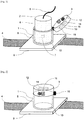
Fig. 1 is a perspective view of an embodiment of the present phototherapy device. -
Fig. 2 is a perspective view of an embodiment of the present phototherapy device. -
Fig. 3 is a perspective view illustrating the positional relationship between irradiation light and the field of observation in the present phototherapy device. -
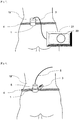
Fig. 4 illustrates a state of use of the present phototherapy device. -
Fig. 5 illustrates a state of use of the present phototherapy device. -
Fig. 6 illustrates a state of use of the present phototherapy device. -
Fig. 7 illustrates another embodiment of the present phototherapy device. -
Fig. 8 illustrates another embodiment of the present phototherapy device. -
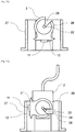
Fig. 9 illustrates another embodiment of the present phototherapy device. -
Fig. 10 illustrates another embodiment of the present phototherapy device. -
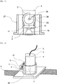
Fig. 11 illustrates another embodiment of the present phototherapy device. -
Fig. 12 illustrates another embodiment of the present phototherapy device. -
Fig. 13 illustrates another embodiment of the present phototherapy device. -
Fig. 14 illustrates another embodiment of the present phototherapy device. -
Fig. 15 is a perspective view illustrating the positional relationship between the irradiation field and the field of observation in another embodiment of the present phototherapy device. -
Fig. 16 illustrates another embodiment of the present phototherapy device. -
Fig. 17 illustrates another embodiment of the present phototherapy device. -
Fig. 18 is a perspective view illustrating the positional relationship between the irradiation field and the field of observation in another embodiment of the present phototherapy device. -
Fig. 19 illustrates another embodiment of the present phototherapy device. -
Fig. 20 illustrates another embodiment of the present phototherapy device. -
Fig. 21 illustrates another embodiment of the present phototherapy device. -
Fig. 22 illustrates another embodiment of the present phototherapy device. -
Fig. 23 illustrates a state of use in another embodiment of the present phototherapy device. -
Fig. 24 illustrates another embodiment of the present phototherapy device. -
Fig. 25 illustrates another embodiment of the present phototherapy device. -
Fig. 26 illustrates another embodiment of the present phototherapy device. -
Fig. 27 illustrates another embodiment of the present phototherapy device. - A phototherapy device according to an embodiment of the present invention will be described below with reference to the accompanying drawings. The phototherapy device of the present embodiment is a device for performing LUTS treatment by irradiating the position of sacral foramina of the patient with light.
-
Fig. 1 is a perspective view of the phototherapy device according to the present embodiment with anirradiation probe 2 inserted in aprobe fixing unit 1. The phototherapy device includes theirradiation probe 2, theprobe fixing unit 1, anobservation module 3, and afixing belt 4. - The
irradiation probe 2 is a member fixed to theprobe fixing unit 1 for irradiating a predetermined irradiation site on the patient's skin with light. Theirradiation probe 2 includes aprobe cable 5 and aprobe casing 6 and atreatment light source 7 is housed in theprobe casing 6. Examples of thetreatment light source 7 include a laser, an LED, a halogen lamp, or a xenon lamp. Thetreatment light source 7 is connected to a power supply for the treatment light source and a switch, which are not illustrated, through theprobe cable 5, and the switch is operated to radiate light to the patient. As for thetreatment light source 7, light may be externally guided into theprobe casing 6 through a waveguide such as an optical fiber. - The
probe casing 6 is formed of, for example, plastic or metal in a hollow cylindrical shape. The shape of theprobe casing 6 is not necessarily cylindrical. - The
probe fixing unit 1 includes aprobe insertion part 8 and apatient contact part 9. Theprobe insertion part 8 is a member for fixing theirradiation probe 2 in theprobe fixing unit 1 toward the patient by inserting theprobe casing 6 therein. - The
patient contact part 9 is a member for fixing theprobe fixing unit 1 to the patient's body surface to irradiate the irradiation site on the patient's body surface with light from thetreatment light source 7 and is provided with atransmission window 10 at the center to allow irradiation light from thetreatment light source 7 to pass through. In the present embodiment, thetransmission window 10 is a hole provided in thepatient contact part 9. Thetransmission window 10 is required only to allow irradiation light to pass through, and thepatient contact part 9 may be partially formed of a material that transmits light, such as glass and plastic film. - The
observation module 3 includes acamera 11, anillumination light source 12, and amodule casing 13. Thecamera 11 is a member for the patient to grasp the irradiation position and area of the photoirradiation site on the back. As forcamera 11, a CCD camera or a CMOS camera can be used. As described later, the image acquired by thecamera 11 is displayed on an external monitor through wired or wireless communication. Theillumination light source 12 is a member that illuminates the field of observation of thecamera 11 to facilitate recognition of the irradiation position and the irradiation area by thecamera 11. As forillumination light source 12, a laser, an LED, a halogen lamp, or a xenon lamp can be used. Themodule casing 13 is a member for holding thecamera 11 and theillumination light source 12 and is equipped with an observationmodule power supply 14 inside for supplying electric power to thecamera 11 and theillumination light source 12. As for observationmodule power supply 14, a primary battery or a secondary battery can be used. Alternatively, electric power may be externally supplied through a cable or the like. - The
observation module 3 and theprobe fixing unit 1 are connected via ahinge 15. Thehinge 15 is a member for moving theobservation module 3 relative to theprobe insertion part 8 and has one end fixed to the upper end (the end on the opposite side to the patient) of theprobe insertion part 8 and the other end fixed to the outer periphery of theobservation module 3.Fig. 2 is the arrangement of theobservation module 3 and theprobe fixing unit 1 when theirradiation probe 2 is not inserted. Theobservation module 3 has an outer diameter set to be equal to or greater than the outer diameter of theprobe insertion part 8 and thus functions as the cap of theprobe insertion part 8 in a state in which theirradiation probe 2 is not inserted and thehinge 15 is closed. In the state as inFig. 2 , theobservation module 3 is positioned on the top of theprobe fixing unit 1, and thecamera 11 in theobservation module 3 is positioned such that the skin can be observed through thetransmission window 10. This configuration enables the patient to visually recognize the marking at the back which is out of sight of the patient. Theillumination light source 12 in theobservation module 3 can illuminate the skin through thetransmission window 10 to make the marking more visible. In this state, theobservation module 3 and thecamera 11 contained in theobservation module 3 are at a position where they interfere with insertion of theirradiation probe 2. - By contrast, the
observation module 3 can be moved to the position at which probe insertion is not hindered by opening thehinge 15 when theirradiation probe 2 is inserted into theprobe insertion part 8. In the present embodiment, theobservation module 3 and theprobe fixing unit 1 are connected via thehinge 15. However, the connection part is not necessarily provided between theobservation module 3 and theprobe fixing unit 1 and they may be detachable from each other. - The fixing
belt 4 is a member for fixing theprobe fixing unit 1 around the patient's body and attached to theprobe fixing unit 1.Fig. 3 is a diagram illustrating the arrangement of anirradiation field 16 of the irradiation light when theirradiation probe 2 is inserted in theprobe insertion part 8 and a field ofobservation 18 of thecamera 11 when theirradiation probe 2 is not inserted and thepatient skin 17 is observed using theobservation module 3. Theirradiation probe 2 and theobservation module 3 are fixed such that the irradiation light and the field ofobservation 18 are arranged coaxially toward thepatient skin 17. Thetreatment light source 7 and thecamera 11 are thus arranged coaxially, so that the irradiation position and the irradiation area can be grasped accurately. Since theirradiation probe 2 is detachable from theprobe fixing unit 1 and positioning can be performed by the lightweightprobe fixing unit 1 alone, the patient can easily perform alignment and fixing by himself/herself even at the back. - A specific usage of the present phototherapy device is described with reference to
Fig. 4 ,Fig. 5, and Fig. 6 . -
Fig. 4 is a diagram illustrating a photoirradiation position of a patient. First of all, the patient's treatment site to be irradiated with light is specified under physician's diagnosis at a hospital or clinic. For example, in LUTS treatment by photoirradiation, the position of sacral foramina to be irradiated with light in the patient'sback 19 is located by palpation or X-ray fluoroscopy. - A physician or any other healthcare worker then makes a marking 20 on the specified treatment site. For example, ink or adhesive sheet can be used as the material of the marking 20. The marking 20 is preferably shaped so as to avoid the irradiation area. For example, a hollow circular shape larger than the irradiation area may be employed, although embodiments are not limited thereto.
- When the patient thereafter performs photoirradiation at home by himself/herself, the patient fixes the
probe fixing unit 1 of the present photoirradiation device in alignment with the marking 20 made at a hospital or clinic. -
Fig. 5 is a diagram illustrating the method of placing theprobe fixing unit 1 in alignment with the marking 20 on the patient. The patient first turns on the observationmodule power supply 14 of theobservation module 3 and fixes the module at a predetermined position of the probe fixing unit 1 (in the present embodiment, the position with thehinge 15 closed). Next, theprobe fixing unit 1 is brought to the back, the state of the back is observed with theobservation module 3 attached to theprobe fixing unit 1, and then the marking 20 is recognized on amonitor 21. Theprobe fixing unit 1 is moved such that the marking 20 is at the center of a field ofobservation 18, and is positioned on thepatient skin 17. In this state, a fixingbelt 4 is wound around the body and theprobe fixing unit 1 is fixed. Subsequently, as illustrated inFig. 6 , theobservation module 3 is removed from theprobe fixing unit 1 and theirradiation probe 2 is inserted. - Conventionally, when the
camera 11 is placed in theprobe fixing unit 1, thecamera 11 is placed such that the marking 20 is captured by thecamera 11 in the appropriately positioned state. If so, theirradiation probe 2 interferes with thecamera 11 when being inserted into theprobe fixing unit 1. The problem is conspicuous particularly when thecamera 11 is arranged such that the optical axis of thecamera 11 is present coaxially relative to the optical axis of thetreatment light source 7 of theirradiation probe 2 fixed on theprobe fixing unit 1 in order to improve the positioning accuracy. In the present phototherapy device, theobservation module 3 can move between a first position at which it overlaps with the path of inserting theirradiation probe 2 and a second position at which it does not overlap with the path, so that the marking 20 can be observed from substantially the same position as theirradiation probe 2 is to be fixed, while theirradiation probe 2 does not interfere with thecamera 11 when being inserted into theprobe fixing unit 1. Accordingly, even when the treatment site is in the back which is out of sight of the patient, and the patient performs photoirradiation by himself/herself, for example, at home, the patient can easily perform alignment and fixing by himself/herself on the back. This configuration enables photoirradiation accurately aiming at the sacral foramina and consequently provides appropriate treatment. The configuration therefore can be widely utilized as a phototherapy device, for example, for LUTS patients. -
Fig. 7 and Fig. 8 are diagrams illustrating another embodiment of the present phototherapy device. Since there are many overlaps between the present embodiment and other embodiments, only the features characterizing the present embodiment will be described below and other descriptions of the configuration are omitted. In the present embodiment, theobservation module 3 and theprobe fixing unit 1 are connected via arotation shaft 22 parallel to the direction of the center axis of theprobe fixing unit 1. Therotation shaft 22 is a member for rotationally moving theobservation module 3. When theirradiation probe 2 is not inserted in theprobe insertion part 8, as illustrated inFig. 8 , theobservation module 3 is positioned such that thepatient skin 17 can be observed with theobservation module 3 through thetransmission window 10, and when theirradiation probe 2 is inserted in theprobe insertion part 8, theobservation module 3 can be easily moved with a smaller force to a position where it does not interfere with the probe insertion as illustrated inFig. 7 . -
Fig. 9 and Fig. 10 are diagrams illustrating another embodiment of the present phototherapy device. Since there are many overlaps between the present embodiment and other embodiments, only the features characterizing the present embodiment will be described below and other descriptions of the configuration are omitted. In the present embodiment, as illustrated inFig. 9 , theobservation module 3 and theprobe fixing unit 1 are connected via arotation shaft 22 vertical to the direction of the center axis of theprobe fixing unit 1. Theobservation module 3 includes alever part 23 for rotating theobservation module 3 in accordance with the movement of theirradiation probe 2 and anobservation part 24 including acamera 11 and anillumination light source 12. Theprobe fixing unit 1 has amovement groove 25 for moving theobservation part 24 to the outside of theprobe insertion part 8 when thelever part 23 is pushed by theirradiation probe 2. When theirradiation probe 2 is not inserted in theprobe insertion part 8, this structure enables an arrangement such that thepatient skin 17 can be observed with theobservation part 24 through thetransmission window 10. When theirradiation probe 2 is inserted in theprobe insertion part 8, as illustrated inFig. 10 , theirradiation probe 2 pushes thelever part 23, so that theobservation module 3 accordingly rotates around therotation shaft 22 and moves out of theprobe insertion part 8 through themovement groove 25. Thus, only by inserting theirradiation probe 2 into theprobe insertion part 8, theobservation module 3 can be easily moved to the position where theobservation module 3 does not interfere with the insertion of theirradiation probe 2. -
Fig. 11 is a perspective view illustrating another embodiment of the present phototherapy device.Fig. 12 is a diagram illustrating asupport casing 27 cut into halves in the present embodiment. Since there are many overlaps between the present embodiment and other embodiments, only the features characterizing the present embodiment will be described below and other descriptions of the configuration are omitted. In the present embodiment, as illustrated inFig. 11 and Fig. 12 , theobservation module 3 includes acamera 11, anillumination light source 12, and arotational housing 26 and is placed inside thesupport casing 27 of theprobe fixing unit 1. Therotational housing 26 further includes arotation shaft 22 connecting theprobe fixing unit 1 and theobservation module 3, and anotch 28. Theirradiation probe 2 is provided with aprobe protrusion 29 to be fitted in thenotch 28.Fig. 13 illustrates a state of the present embodiment when theirradiation probe 2 is not inserted. In this case, thecamera 11 and theillumination light source 12 face the patient'sskin 17 to enable the patient to grasp the irradiation position and the irradiation area and accurately fix theprobe fixing unit 1 at an appropriate position.Fig. 14 illustrates a state of the present embodiment when theirradiation probe 2 is inserted. When theirradiation probe 2 is inserted, theprobe protrusion 29 fits in thenotch 28 and rotates therotational housing 26 around therotation shaft 22. Then, thecamera 11 and theillumination light source 12 move from the patient'sskin 17 side, and instead thetreatment light source 7 equipped in theirradiation probe 2 is positioned in the direction in which the patient'sskin 17 can be irradiated with irradiation light.Fig. 15 is a diagram illustrating the arrangement of irradiation light when theirradiation probe 2 is inserted in theprobe insertion part 8 and the field ofobservation 18 of thecamera 11 when theirradiation probe 2 is not inserted and the patient'sskin 17 is observed with theobservation module 3, in the present embodiment. Theirradiation probe 2 and theobservation module 3 are fixed such that theirradiation field 16 and the field ofobservation 18 are arranged coaxially toward the patient'sskin 17. With such a configuration, the field ofobservation 18 can be moved only by inserting theirradiation probe 2. -
Fig. 16 is a perspective view illustrating another embodiment of the present phototherapy device. Since there are many overlaps between the present embodiment and other embodiments, only the features characterizing the present embodiment will be described below and other descriptions of the configuration are omitted. In the present embodiment, theobservation module 3 is placed on a side surface of theprobe fixing unit 1, and anobservation mirror 30 is placed in theprobe fixing unit 1. Theobservation mirror 30 is connected to theprobe fixing unit 1 via a mirror-movinghinge 31. Theirradiation probe 2 is shaped so as to avoid theobservation mirror 30 when being inserted.Fig. 17 illustrates a state of the present embodiment when theirradiation probe 2 is not inserted. In this case, theobservation mirror 30 extends into theprobe fixing unit 1, and theobservation mirror 30 is arranged such that the field ofobservation 18 of thecamera 11 in theobservation module 3 and light of theillumination light source 12 are directed toward the patient'sskin 17 via the observation mirror. In this case, as illustrated inFig. 18 , theobservation module 3 and theobservation mirror 30 are arranged such that the field ofobservation 18 reflected by theobservation mirror 30 and theirradiation field 16 of irradiation light radiated from thetreatment light source 7 in theirradiation probe 2 are arranged coaxially. With such a configuration, when theirradiation probe 2 is not inserted, the field ofobservation 18 can be observed with theobservation mirror 30, and when theirradiation probe 2 is inserted, theobservation mirror 30 is moved only by pushing theobservation mirror 30, and theirradiation probe 2 can be fixed such that the field ofobservation 18 of thecamera 11 inside theobservation module 3 and the irradiation light from thetreatment light source 7 are coaxial. -
Fig. 19 is a perspective view illustrating another embodiment of the present phototherapy device. Since there are many overlaps between the present embodiment and other embodiments, only the features characterizing the present embodiment will be described below and other descriptions of the configuration are omitted. In the present embodiment, theobservation module 3 has apositioning guide 32. AlthoughFig. 19 illustrates an example in which theguide 32 is provided in the phototherapy device described in the first embodiment by way of an example, theguide 32 may be provided in the phototherapy device described in the other embodiments. Thepositioning guide 32 may be provided with a physical marker that can be caught by thecamera 11 as illustrated inFig. 19 or may have the function of being electronically displayed on themonitor 21 as illustrated inFig. 20 . This function enables the patient to easily learn the relationship between the position of the marking 20 and the current position of theprobe fixing unit 1 and make alignment more accurately. -
Fig. 21 is a perspective view illustrating another embodiment of the present phototherapy device. Since there are many overlaps between the present embodiment and other embodiments, only the features characterizing the present embodiment will be described below and other descriptions of the configuration are omitted. In the present embodiment, afine adjustment mechanism 33 is provided between theprobe insertion part 8 of theprobe fixing unit 1 and thepatient contact part 9, wherein the mechanism moves theprobe insertion part 8 and thepatient contact part 9 relative to each other and can fix them at the position where movement terminates. Thefine adjustment mechanism 33 is a member for finely adjusting the positional relationship between theprobe insertion part 8 and thepatient contact part 9, and can adopt a screw feed mechanism or a spring type moving mechanism. In the present embodiment, it is preferable if thetransmission window 10 provided in thepatient contact part 9 is larger than the area of the inner periphery of theprobe insertion part 8. With thefine adjustment mechanism 33, even when theprobe fixing unit 1 is out of alignment with the marking 20 because of body movement and the like after the patient once moves theprobe fixing unit 1 and positions it in alignment with the marking 20 on the patient'sskin 17 and fixes it using the fixingbelt 4, the patient can promptly make fine adjustment by moving the position of theprobe insertion part 8 relative to thepatient contact part 9 without taking off the fixingbelt 4. AlthoughFig. 21 illustrates an example in which thefine adjustment mechanism 33 is provided in the phototherapy device described in the first embodiment by way of an example, thefine adjustment mechanism 33 may be provided in the phototherapy device described in the other embodiments. -
Fig. 22 is a perspective view illustrating another embodiment of the present phototherapy device. Since there are many overlaps between the present embodiment and other embodiments, only the features characterizing the present embodiment will be described below and other descriptions of the configuration are omitted. In the present embodiment, aflexible medium 34 is provided beneath thepatient contact part 9. For example, a resin cushion material or an air cushion may be used as theflexible medium 34. With this configuration, even when the irradiation site is an uneven surface of the patient body as illustrated inFig. 23 , theprobe fixing unit 1 can be fitted on the body surface. Thus, even when body movement and the like occur, theprobe fixing unit 1 can be securely fixed to the patient'sback 19 to enable appropriate radiation. AlthoughFig. 22 illustrates an example in which theflexible medium 34 is provided in the phototherapy device described in the first embodiment by way of an example, theflexible medium 34 may be provided in the phototherapy device described in the other embodiments. -
Fig. 24 is a perspective view illustrating another embodiment of the present phototherapy device. Since there are many overlaps between the present embodiment and other embodiments, only the features characterizing the present embodiment will be described below and other descriptions of the configuration are omitted. In the present embodiment, the fixingbelt 4 is detachable from theprobe fixing unit 1. As illustrated inFig. 25 , the fixingbelt 4 includes abelt body 35, abelt fixing part 36, abelt attachment part 37, and a throughhole 38. Thebelt fixing part 36 is a member for the patient to fix the belt to the body, and can adopt a hook and loop fastener, an adhesive tape, or a clip can be used. Thebelt attachment part 37 is a member for allowing the belt to be attached to/detached from theprobe fixing unit 1 and can adopt, for example, a configuration of screwing or pinning to theprobe fixing unit 1 through holes in the belt. The throughhole 38 enables a configuration to appropriately apply the irradiation light radiated from thetreatment light source 7 in theirradiation probe 2 to the patient'sback 19 without being blocked by thebelt body 35. With this configuration, when the belt becomes dirty because of the frequent use of the present phototherapy device, the belt alone can be removed and washed or replaced, and thus the belt can be kept clean. -
Fig. 26 is a perspective view illustrating another embodiment of the present phototherapy device. Since there are many overlaps between the present embodiment and other embodiments, only the features characterizing the present embodiment will be described below and other descriptions of the configuration are omitted. In the present embodiment, two fixingbelts 4 are removably attached to thebelt attachment part 37 of theprobe fixing unit 1. As illustrated inFig. 27 , each of two fixingbelts 4 includes a frontbelt fixing part 39 and a sidebelt fixing part 40. Thebelt fixing part 40 is a member for the patient to fix the belt to the body, and can adopt a hook and loop fastener, an adhesive tape, or a clip. In this configuration, the patient first moves theprobe fixing unit 1 in alignment with the marking 20 and positions it on thepatient skin 17 while keeping the sidebelt fixing part 40 fixed. After fixing the belt to the body with the frontbelt fixing parts 39, the patient can further tighten the belt by once releasing the sidebelt fixing part 40 and then pulling it to surely fix theprobe fixing unit 1 to the body. - In the above embodiments, the phototherapy device according to the present invention is used for LUTS treatment by irradiating the position of the sacral foramina of a patient with light. However, the phototherapy device according to the present invention is applicable to treatment of other diseases. For example, the applications include dyschezia treatment, functional dyspepsia treatment, sexual dysfunction treatment, inflammatory bowel treatment, pain relief, nephropathy treatment, rheumatism treatment, sudden deafness treatment, atopic dermatitis treatment, and wound healing acceleration.
- In the above embodiments, it is explained that irradiation light is radiated from the irradiation probe toward a living body. However, under the condition in which the treatment site is located at the position which is out of sight of the patient, such as the back, and the device is for the patient to perform energy irradiation by himself/herself at home, the similar effects can be achieved using radiation energy other than laser light. Examples of other applicable radiation energy include electricity, electromagnetic waves (including magnetism, electric waves, light, and low frequency), sound (including ultrasonic wave and soundwave), and heat.
-
- 1
- Probe fixing unit
- 2
- Irradiation probe
- 3
- Observation module
- 4
- Fixing belt
- 5
- Probe cable
- 6
- Probe casing
- 7
- Treatment light source
- 8
- Probe insertion part
- 9
- Patient contact part
- 10
- Transmission window
- 11
- Camera
- 12
- Irradiation light source
- 13
- Module casing
- 14
- Observation module power supply
- 15
- Hinge
- 16
- Irradiation field
- 17
- Patient's skin
- 18
- Field of observation
- 19
- Patient's back
- 20
- Marking
- 21
- Monitor
- 22
- Rotation shaft
- 23
- Lever part
- 24
- Observation part
- 25
- Movement groove
- 26
- Rotational housing
- 27
- Support casing
- 28
- Notch
- 29
- Probe protrusion
- 30
- Observation mirror
- 31
- Mirror-moving hinge
- 32
- Positioning guide
- 33
- Fine adjustment mechanism
- 34
- Flexible medium
- 35
- Belt body
- 36
- Belt fixing part
- 37
- Belt attachment/detachment part
- 38
- Through hole
- 39
- Front belt fixing part
- 40
- Side belt fixing part
Claims (11)
- A phototherapy device comprising:an irradiation probe for radiating irradiation light toward a living body;a probe fixing unit into which the irradiation probe is inserted and at the same time fixed on a living body;an observation module placed on the probe fixing unit and provided with an observation means for observing an irradiation site irradiated with irradiation light which is radiated to the living body; anda moving means capable of moving the observation module to a space where the irradiation probe is to be placed in the probe fixing unit during observation of the irradiation site.
- The phototherapy device according to claim 1, wherein an irradiation field of irradiation light from the irradiation probe and a field of observation of the observation module are coaxial toward an irradiation site on a living body.
- The phototherapy device according to claim 1, wherein the moving means is a hinge formed between the probe fixing unit and the observation module.
- The phototherapy device according to claim 1, wherein the moving means is a rotation shaft formed between the probe fixing unit and the observation module.
- The phototherapy device according to claim 1, wherein the moving means is rotated by insertion of the irradiation probe into the probe fixing unit and moves the observation module.
- The phototherapy device according to claim 1, wherein the observation module is further provided with an observation mirror, and the moving means is capable of moving the observation mirror into a space where the irradiation probe is to be placed in the probe fixing unit.
- The phototherapy device according to any one of claims 1 to 6, wherein the observation module is provided with a positioning guide.
- The phototherapy device according to any one of claims 1 to 6, wherein the probe fixing unit is provided with a fine adjustment mechanism.
- The phototherapy device according to any one of claims 1 to 6, wherein a flexible medium is formed at a part of the probe fixing unit.
- The phototherapy device according to any one of claims 1 to 9, wherein the probe fixing unit is provided with a removable fixing belt.
- The phototherapy device according to claim 10, wherein the fixing belt is provided with two belts each equipped with a front belt fixing part and a side belt fixing part.
Applications Claiming Priority (2)
| Application Number | Priority Date | Filing Date | Title |
|---|---|---|---|
| JP2017107907 | 2017-05-31 | ||
| PCT/JP2018/019441 WO2018221284A1 (en) | 2017-05-31 | 2018-05-21 | Phototherapeutic apparatus |
Publications (3)
| Publication Number | Publication Date |
|---|---|
| EP3636317A1 true EP3636317A1 (en) | 2020-04-15 |
| EP3636317A4 EP3636317A4 (en) | 2020-04-15 |
| EP3636317B1 EP3636317B1 (en) | 2023-07-05 |
Family
ID=64456228
Family Applications (1)
| Application Number | Title | Priority Date | Filing Date |
|---|---|---|---|
| EP18810824.5A Active EP3636317B1 (en) | 2017-05-31 | 2018-05-21 | Phototherapeutic apparatus |
Country Status (8)
| Country | Link |
|---|---|
| US (1) | US11235170B2 (en) |
| EP (1) | EP3636317B1 (en) |
| JP (1) | JP6782839B2 (en) |
| KR (2) | KR102689161B1 (en) |
| CN (1) | CN110662580B (en) |
| CA (1) | CA3064365A1 (en) |
| ES (1) | ES2951820T3 (en) |
| WO (1) | WO2018221284A1 (en) |
Cited By (1)
| Publication number | Priority date | Publication date | Assignee | Title |
|---|---|---|---|---|
| IL259606B1 (en) * | 2017-11-17 | 2023-12-01 | Ideal Eng Cc | Securing Device and Method for Securing Handheld/Portable phototherapy apparatus |
Families Citing this family (6)
| Publication number | Priority date | Publication date | Assignee | Title |
|---|---|---|---|---|
| US12502550B2 (en) * | 2020-07-21 | 2025-12-23 | Teijin Pharma Limited | Light beam irradiation apparatus |
| KR102572369B1 (en) | 2020-11-11 | 2023-08-30 | 단국대학교 천안캠퍼스 산학협력단 | Photobiomodulation test chamber device for cell and animals |
| US20240009477A1 (en) * | 2020-11-30 | 2024-01-11 | Teijin Pharma Limited | Phototherapeutic apparatus |
| CN114028729B (en) * | 2021-12-02 | 2023-10-20 | 固安翌光科技有限公司 | Phototherapy device |
| WO2025160383A1 (en) * | 2024-01-25 | 2025-07-31 | Case Western Reserve University | Treating pain with photobiomodulation applied transcutaneously |
| WO2025160368A1 (en) * | 2024-01-25 | 2025-07-31 | Case Western Reserve University | Using a surgical tool to silence small fibers within a nerve through a surgical opening |
Family Cites Families (29)
| Publication number | Priority date | Publication date | Assignee | Title |
|---|---|---|---|---|
| JPS5442096A (en) | 1977-09-09 | 1979-04-03 | Mitsutoyo Seisakusho | Method machining gear |
| JPS6027740Y2 (en) | 1980-08-18 | 1985-08-21 | スズキ株式会社 | motorcycle rear mudguard |
| US6245059B1 (en) * | 1999-04-07 | 2001-06-12 | Visx, Incorporated | Offset ablation profiles for treatment of irregular astigmation |
| US7525696B2 (en) * | 2004-06-07 | 2009-04-28 | Carnevali Jeffrey D | Locking holster for UPC scanner |
| US20070156208A1 (en) * | 2005-11-08 | 2007-07-05 | David Havell | Method and Apparatus for Bi-Axial Light Treatment |
| CN101677835A (en) | 2007-04-10 | 2010-03-24 | 强度创新公司 | Self-contained handpiece and method for optical tissue surface treatment |
| JP5284650B2 (en) | 2008-01-22 | 2013-09-11 | 国立大学法人 千葉大学 | Applications of lasers used to improve and / or treat dysuria |
| CA2718434A1 (en) * | 2008-03-18 | 2009-09-24 | Photothera, Inc. | Method and apparatus for irradiating a surface with continuous-wave or pulsed light |
| EP2334271B1 (en) | 2008-08-25 | 2015-04-08 | WaveLight GmbH | Coupling of an eye to a laser device |
| JP5739888B2 (en) | 2010-07-28 | 2015-06-24 | ヤーマン株式会社 | Pain relief device |
| JPWO2012060075A1 (en) * | 2010-11-05 | 2014-05-12 | パナソニック株式会社 | Phototherapy device |
| US8536547B2 (en) * | 2011-01-20 | 2013-09-17 | Accuray Incorporated | Ring gantry radiation treatment delivery system with dynamically controllable inward extension of treatment head |
| US10369051B2 (en) * | 2012-05-30 | 2019-08-06 | Ellex R&D Pty Ltd | Reflex coaxial illuminator |
| EP2979651B1 (en) | 2013-03-29 | 2019-12-25 | FUJIFILM Corporation | Endoscopic surgery device |
| CA2911035C (en) * | 2013-05-02 | 2022-05-10 | Atonarp Inc. | Monitor and system for monitoring an organism |
| CN105658277B (en) * | 2013-11-01 | 2018-12-28 | 皇家飞利浦有限公司 | Light therapy apparatus |
| US10064940B2 (en) * | 2013-12-11 | 2018-09-04 | Siva Therapeutics Inc. | Multifunctional radiation delivery apparatus and method |
| JP6362895B2 (en) * | 2014-03-24 | 2018-07-25 | テルモ株式会社 | Therapy device |
| JP2015198743A (en) * | 2014-04-07 | 2015-11-12 | 並木精密宝石株式会社 | Laser radiation treatment equipment |
| CA2958210C (en) | 2014-08-15 | 2023-09-26 | Axonics Modulation Technologies, Inc. | Integrated electromyographic clinician programmer for use with an implantable neurostimulator |
| KR102268706B1 (en) * | 2014-09-22 | 2021-06-24 | 재단법인대구경북과학기술원 | Portable spectral imaging device, user mobile terminal, method and software program for diagnosis and management of skin |
| KR101589737B1 (en) * | 2014-10-16 | 2016-01-28 | 이창용 | Device for Guiding Light for Dental Treatment |
| WO2016064675A1 (en) * | 2014-10-20 | 2016-04-28 | Lexington International, Llc | Light emitting hands free device |
| CN204562371U (en) * | 2015-03-18 | 2015-08-19 | 深圳市中科微光医疗器械技术有限公司 | Cardiac ablation system and dual pathways probe thereof |
| CN104941073A (en) * | 2015-06-24 | 2015-09-30 | 刘立倩 | Total skin irradiation treatment device |
| CN205494696U (en) * | 2016-03-31 | 2016-08-24 | 浙江光博士医疗科技有限公司 | Shine angle and position adjustable phototherapy device |
| CN205729993U (en) * | 2016-05-12 | 2016-11-30 | 京东方科技集团股份有限公司 | Illumination armarium |
| KR101922137B1 (en) * | 2016-07-22 | 2018-11-27 | 재단법인대구경북과학기술원 | Portable spectral imaging device, user mobile terminal, method and software program for diagnosis and management of skin |
| CN106237534B (en) * | 2016-08-29 | 2018-06-29 | 武汉亚格光电技术股份有限公司 | Intelligent nevus flammeus photodynamic therapeutic instrument system |
-
2018
- 2018-05-21 CN CN201880036040.8A patent/CN110662580B/en active Active
- 2018-05-21 ES ES18810824T patent/ES2951820T3/en active Active
- 2018-05-21 US US16/617,194 patent/US11235170B2/en active Active
- 2018-05-21 JP JP2019522123A patent/JP6782839B2/en active Active
- 2018-05-21 KR KR1020197037483A patent/KR102689161B1/en active Active
- 2018-05-21 EP EP18810824.5A patent/EP3636317B1/en active Active
- 2018-05-21 CA CA3064365A patent/CA3064365A1/en active Pending
- 2018-05-21 WO PCT/JP2018/019441 patent/WO2018221284A1/en not_active Ceased
- 2018-05-21 KR KR1020237041456A patent/KR20230167159A/en not_active Ceased
Cited By (2)
| Publication number | Priority date | Publication date | Assignee | Title |
|---|---|---|---|---|
| IL259606B1 (en) * | 2017-11-17 | 2023-12-01 | Ideal Eng Cc | Securing Device and Method for Securing Handheld/Portable phototherapy apparatus |
| IL259606B2 (en) * | 2017-11-17 | 2024-04-01 | Ideal Eng Cc | Safety device and method for securing a portable / hand-held phototherapy device |
Also Published As
| Publication number | Publication date |
|---|---|
| JPWO2018221284A1 (en) | 2019-11-07 |
| CN110662580B (en) | 2021-11-09 |
| CN110662580A (en) | 2020-01-07 |
| JP6782839B2 (en) | 2020-11-11 |
| WO2018221284A1 (en) | 2018-12-06 |
| EP3636317B1 (en) | 2023-07-05 |
| EP3636317A4 (en) | 2020-04-15 |
| KR20230167159A (en) | 2023-12-07 |
| ES2951820T3 (en) | 2023-10-25 |
| KR20200014798A (en) | 2020-02-11 |
| KR102689161B1 (en) | 2024-07-26 |
| US11235170B2 (en) | 2022-02-01 |
| US20210121712A1 (en) | 2021-04-29 |
| CA3064365A1 (en) | 2018-12-06 |
Similar Documents
| Publication | Publication Date | Title |
|---|---|---|
| US11235170B2 (en) | Phototherapeutic apparatus | |
| US12144999B2 (en) | Device for delivering precision phototherapy | |
| US9682249B2 (en) | Transcranial magnetic stimulation system | |
| US9114184B2 (en) | Device for the hygienisation of medical instruments | |
| JP2022511811A (en) | Systems and methods for treating eye conditions | |
| WO2011094758A3 (en) | Methods and devices for crosslinking of corneal collagen and for treatment of disorders of the eye | |
| EP2489404A3 (en) | Wearable device for providing phototherapy to the brain | |
| KR20160057933A (en) | Catheter Device with Endoscope | |
| CN112312965B (en) | Chair-type light therapeutic device | |
| US10821296B2 (en) | Systems and methods for the automated delivery of photobiomodulation therapy to a patient | |
| CN207412529U (en) | A kind of low-energy laser therapeutic instrument for rehabilitation based on red laser | |
| KR20160053552A (en) | Device for generating high intensity focused ultrasound | |
| CN118320319B (en) | Semiconductor laser treatment device and system | |
| GB2573033A (en) | Improvements to orthopaedic pins | |
| CN108014430A (en) | Ultrasonic therapeutic apparatus for big brain rehabilitation | |
| RU45088U1 (en) | LIGHT THERAPEUTIC DEVICE | |
| CN115518300A (en) | Therapeutic equipment | |
| JP2018157894A (en) | Optical treatment apparatus |
Legal Events
| Date | Code | Title | Description |
|---|---|---|---|
| STAA | Information on the status of an ep patent application or granted ep patent |
Free format text: STATUS: THE INTERNATIONAL PUBLICATION HAS BEEN MADE |
|
| PUAI | Public reference made under article 153(3) epc to a published international application that has entered the european phase |
Free format text: ORIGINAL CODE: 0009012 |
|
| STAA | Information on the status of an ep patent application or granted ep patent |
Free format text: STATUS: REQUEST FOR EXAMINATION WAS MADE |
|
| 17P | Request for examination filed |
Effective date: 20191205 |
|
| A4 | Supplementary search report drawn up and despatched |
Effective date: 20200217 |
|
| AK | Designated contracting states |
Kind code of ref document: A1 Designated state(s): AL AT BE BG CH CY CZ DE DK EE ES FI FR GB GR HR HU IE IS IT LI LT LU LV MC MK MT NL NO PL PT RO RS SE SI SK SM TR |
|
| AX | Request for extension of the european patent |
Extension state: BA ME |
|
| DAV | Request for validation of the european patent (deleted) | ||
| DAX | Request for extension of the european patent (deleted) | ||
| GRAP | Despatch of communication of intention to grant a patent |
Free format text: ORIGINAL CODE: EPIDOSNIGR1 |
|
| STAA | Information on the status of an ep patent application or granted ep patent |
Free format text: STATUS: GRANT OF PATENT IS INTENDED |
|
| INTG | Intention to grant announced |
Effective date: 20201223 |
|
| GRAJ | Information related to disapproval of communication of intention to grant by the applicant or resumption of examination proceedings by the epo deleted |
Free format text: ORIGINAL CODE: EPIDOSDIGR1 |
|
| STAA | Information on the status of an ep patent application or granted ep patent |
Free format text: STATUS: REQUEST FOR EXAMINATION WAS MADE |
|
| STAA | Information on the status of an ep patent application or granted ep patent |
Free format text: STATUS: EXAMINATION IS IN PROGRESS |
|
| INTC | Intention to grant announced (deleted) | ||
| 17Q | First examination report despatched |
Effective date: 20210317 |
|
| GRAP | Despatch of communication of intention to grant a patent |
Free format text: ORIGINAL CODE: EPIDOSNIGR1 |
|
| STAA | Information on the status of an ep patent application or granted ep patent |
Free format text: STATUS: GRANT OF PATENT IS INTENDED |
|
| INTG | Intention to grant announced |
Effective date: 20221027 |
|
| GRAJ | Information related to disapproval of communication of intention to grant by the applicant or resumption of examination proceedings by the epo deleted |
Free format text: ORIGINAL CODE: EPIDOSDIGR1 |
|
| STAA | Information on the status of an ep patent application or granted ep patent |
Free format text: STATUS: EXAMINATION IS IN PROGRESS |
|
| GRAP | Despatch of communication of intention to grant a patent |
Free format text: ORIGINAL CODE: EPIDOSNIGR1 |
|
| STAA | Information on the status of an ep patent application or granted ep patent |
Free format text: STATUS: GRANT OF PATENT IS INTENDED |
|
| INTC | Intention to grant announced (deleted) | ||
| INTG | Intention to grant announced |
Effective date: 20230208 |
|
| GRAS | Grant fee paid |
Free format text: ORIGINAL CODE: EPIDOSNIGR3 |
|
| GRAA | (expected) grant |
Free format text: ORIGINAL CODE: 0009210 |
|
| STAA | Information on the status of an ep patent application or granted ep patent |
Free format text: STATUS: THE PATENT HAS BEEN GRANTED |
|
| AK | Designated contracting states |
Kind code of ref document: B1 Designated state(s): AL AT BE BG CH CY CZ DE DK EE ES FI FR GB GR HR HU IE IS IT LI LT LU LV MC MK MT NL NO PL PT RO RS SE SI SK SM TR |
|
| REG | Reference to a national code |
Ref country code: CH Ref legal event code: EP |
|
| REG | Reference to a national code |
Ref country code: AT Ref legal event code: REF Ref document number: 1584271 Country of ref document: AT Kind code of ref document: T Effective date: 20230715 |
|
| REG | Reference to a national code |
Ref country code: DE Ref legal event code: R096 Ref document number: 602018052932 Country of ref document: DE |
|
| REG | Reference to a national code |
Ref country code: IE Ref legal event code: FG4D |
|
| REG | Reference to a national code |
Ref country code: ES Ref legal event code: FG2A Ref document number: 2951820 Country of ref document: ES Kind code of ref document: T3 Effective date: 20231025 Ref country code: LT Ref legal event code: MG9D |
|
| REG | Reference to a national code |
Ref country code: NL Ref legal event code: MP Effective date: 20230705 |
|
| REG | Reference to a national code |
Ref country code: AT Ref legal event code: MK05 Ref document number: 1584271 Country of ref document: AT Kind code of ref document: T Effective date: 20230705 |
|
| PG25 | Lapsed in a contracting state [announced via postgrant information from national office to epo] |
Ref country code: NL Free format text: LAPSE BECAUSE OF FAILURE TO SUBMIT A TRANSLATION OF THE DESCRIPTION OR TO PAY THE FEE WITHIN THE PRESCRIBED TIME-LIMIT Effective date: 20230705 |
|
| PG25 | Lapsed in a contracting state [announced via postgrant information from national office to epo] |
Ref country code: GR Free format text: LAPSE BECAUSE OF FAILURE TO SUBMIT A TRANSLATION OF THE DESCRIPTION OR TO PAY THE FEE WITHIN THE PRESCRIBED TIME-LIMIT Effective date: 20231006 |
|
| PG25 | Lapsed in a contracting state [announced via postgrant information from national office to epo] |
Ref country code: IS Free format text: LAPSE BECAUSE OF FAILURE TO SUBMIT A TRANSLATION OF THE DESCRIPTION OR TO PAY THE FEE WITHIN THE PRESCRIBED TIME-LIMIT Effective date: 20231105 |
|
| PG25 | Lapsed in a contracting state [announced via postgrant information from national office to epo] |
Ref country code: SE Free format text: LAPSE BECAUSE OF FAILURE TO SUBMIT A TRANSLATION OF THE DESCRIPTION OR TO PAY THE FEE WITHIN THE PRESCRIBED TIME-LIMIT Effective date: 20230705 Ref country code: RS Free format text: LAPSE BECAUSE OF FAILURE TO SUBMIT A TRANSLATION OF THE DESCRIPTION OR TO PAY THE FEE WITHIN THE PRESCRIBED TIME-LIMIT Effective date: 20230705 Ref country code: PT Free format text: LAPSE BECAUSE OF FAILURE TO SUBMIT A TRANSLATION OF THE DESCRIPTION OR TO PAY THE FEE WITHIN THE PRESCRIBED TIME-LIMIT Effective date: 20231106 Ref country code: NO Free format text: LAPSE BECAUSE OF FAILURE TO SUBMIT A TRANSLATION OF THE DESCRIPTION OR TO PAY THE FEE WITHIN THE PRESCRIBED TIME-LIMIT Effective date: 20231005 Ref country code: LV Free format text: LAPSE BECAUSE OF FAILURE TO SUBMIT A TRANSLATION OF THE DESCRIPTION OR TO PAY THE FEE WITHIN THE PRESCRIBED TIME-LIMIT Effective date: 20230705 Ref country code: LT Free format text: LAPSE BECAUSE OF FAILURE TO SUBMIT A TRANSLATION OF THE DESCRIPTION OR TO PAY THE FEE WITHIN THE PRESCRIBED TIME-LIMIT Effective date: 20230705 Ref country code: IS Free format text: LAPSE BECAUSE OF FAILURE TO SUBMIT A TRANSLATION OF THE DESCRIPTION OR TO PAY THE FEE WITHIN THE PRESCRIBED TIME-LIMIT Effective date: 20231105 Ref country code: HR Free format text: LAPSE BECAUSE OF FAILURE TO SUBMIT A TRANSLATION OF THE DESCRIPTION OR TO PAY THE FEE WITHIN THE PRESCRIBED TIME-LIMIT Effective date: 20230705 Ref country code: GR Free format text: LAPSE BECAUSE OF FAILURE TO SUBMIT A TRANSLATION OF THE DESCRIPTION OR TO PAY THE FEE WITHIN THE PRESCRIBED TIME-LIMIT Effective date: 20231006 Ref country code: FI Free format text: LAPSE BECAUSE OF FAILURE TO SUBMIT A TRANSLATION OF THE DESCRIPTION OR TO PAY THE FEE WITHIN THE PRESCRIBED TIME-LIMIT Effective date: 20230705 Ref country code: AT Free format text: LAPSE BECAUSE OF FAILURE TO SUBMIT A TRANSLATION OF THE DESCRIPTION OR TO PAY THE FEE WITHIN THE PRESCRIBED TIME-LIMIT Effective date: 20230705 |
|
| PG25 | Lapsed in a contracting state [announced via postgrant information from national office to epo] |
Ref country code: PL Free format text: LAPSE BECAUSE OF FAILURE TO SUBMIT A TRANSLATION OF THE DESCRIPTION OR TO PAY THE FEE WITHIN THE PRESCRIBED TIME-LIMIT Effective date: 20230705 |
|
| REG | Reference to a national code |
Ref country code: DE Ref legal event code: R097 Ref document number: 602018052932 Country of ref document: DE |
|
| PG25 | Lapsed in a contracting state [announced via postgrant information from national office to epo] |
Ref country code: SM Free format text: LAPSE BECAUSE OF FAILURE TO SUBMIT A TRANSLATION OF THE DESCRIPTION OR TO PAY THE FEE WITHIN THE PRESCRIBED TIME-LIMIT Effective date: 20230705 Ref country code: RO Free format text: LAPSE BECAUSE OF FAILURE TO SUBMIT A TRANSLATION OF THE DESCRIPTION OR TO PAY THE FEE WITHIN THE PRESCRIBED TIME-LIMIT Effective date: 20230705 Ref country code: EE Free format text: LAPSE BECAUSE OF FAILURE TO SUBMIT A TRANSLATION OF THE DESCRIPTION OR TO PAY THE FEE WITHIN THE PRESCRIBED TIME-LIMIT Effective date: 20230705 Ref country code: DK Free format text: LAPSE BECAUSE OF FAILURE TO SUBMIT A TRANSLATION OF THE DESCRIPTION OR TO PAY THE FEE WITHIN THE PRESCRIBED TIME-LIMIT Effective date: 20230705 Ref country code: CZ Free format text: LAPSE BECAUSE OF FAILURE TO SUBMIT A TRANSLATION OF THE DESCRIPTION OR TO PAY THE FEE WITHIN THE PRESCRIBED TIME-LIMIT Effective date: 20230705 Ref country code: SK Free format text: LAPSE BECAUSE OF FAILURE TO SUBMIT A TRANSLATION OF THE DESCRIPTION OR TO PAY THE FEE WITHIN THE PRESCRIBED TIME-LIMIT Effective date: 20230705 |
|
| PLBE | No opposition filed within time limit |
Free format text: ORIGINAL CODE: 0009261 |
|
| STAA | Information on the status of an ep patent application or granted ep patent |
Free format text: STATUS: NO OPPOSITION FILED WITHIN TIME LIMIT |
|
| 26N | No opposition filed |
Effective date: 20240408 |
|
| PG25 | Lapsed in a contracting state [announced via postgrant information from national office to epo] |
Ref country code: SI Free format text: LAPSE BECAUSE OF FAILURE TO SUBMIT A TRANSLATION OF THE DESCRIPTION OR TO PAY THE FEE WITHIN THE PRESCRIBED TIME-LIMIT Effective date: 20230705 |
|
| PG25 | Lapsed in a contracting state [announced via postgrant information from national office to epo] |
Ref country code: BG Free format text: LAPSE BECAUSE OF FAILURE TO SUBMIT A TRANSLATION OF THE DESCRIPTION OR TO PAY THE FEE WITHIN THE PRESCRIBED TIME-LIMIT Effective date: 20230705 |
|
| PG25 | Lapsed in a contracting state [announced via postgrant information from national office to epo] |
Ref country code: BG Free format text: LAPSE BECAUSE OF FAILURE TO SUBMIT A TRANSLATION OF THE DESCRIPTION OR TO PAY THE FEE WITHIN THE PRESCRIBED TIME-LIMIT Effective date: 20230705 |
|
| REG | Reference to a national code |
Ref country code: CH Ref legal event code: PL |
|
| PG25 | Lapsed in a contracting state [announced via postgrant information from national office to epo] |
Ref country code: MC Free format text: LAPSE BECAUSE OF FAILURE TO SUBMIT A TRANSLATION OF THE DESCRIPTION OR TO PAY THE FEE WITHIN THE PRESCRIBED TIME-LIMIT Effective date: 20230705 |
|
| PG25 | Lapsed in a contracting state [announced via postgrant information from national office to epo] |
Ref country code: LU Free format text: LAPSE BECAUSE OF NON-PAYMENT OF DUE FEES Effective date: 20240521 |
|
| PG25 | Lapsed in a contracting state [announced via postgrant information from national office to epo] |
Ref country code: MC Free format text: LAPSE BECAUSE OF FAILURE TO SUBMIT A TRANSLATION OF THE DESCRIPTION OR TO PAY THE FEE WITHIN THE PRESCRIBED TIME-LIMIT Effective date: 20230705 Ref country code: LU Free format text: LAPSE BECAUSE OF NON-PAYMENT OF DUE FEES Effective date: 20240521 Ref country code: CH Free format text: LAPSE BECAUSE OF NON-PAYMENT OF DUE FEES Effective date: 20240531 |
|
| REG | Reference to a national code |
Ref country code: BE Ref legal event code: MM Effective date: 20240531 |
|
| PG25 | Lapsed in a contracting state [announced via postgrant information from national office to epo] |
Ref country code: IE Free format text: LAPSE BECAUSE OF NON-PAYMENT OF DUE FEES Effective date: 20240521 |
|
| PG25 | Lapsed in a contracting state [announced via postgrant information from national office to epo] |
Ref country code: BE Free format text: LAPSE BECAUSE OF NON-PAYMENT OF DUE FEES Effective date: 20240531 |
|
| PGFP | Annual fee paid to national office [announced via postgrant information from national office to epo] |
Ref country code: DE Payment date: 20250521 Year of fee payment: 8 |
|
| PGFP | Annual fee paid to national office [announced via postgrant information from national office to epo] |
Ref country code: GB Payment date: 20250527 Year of fee payment: 8 |
|
| PGFP | Annual fee paid to national office [announced via postgrant information from national office to epo] |
Ref country code: IT Payment date: 20250527 Year of fee payment: 8 |
|
| PGFP | Annual fee paid to national office [announced via postgrant information from national office to epo] |
Ref country code: FR Payment date: 20250528 Year of fee payment: 8 |
|
| PG25 | Lapsed in a contracting state [announced via postgrant information from national office to epo] |
Ref country code: CY Free format text: LAPSE BECAUSE OF FAILURE TO SUBMIT A TRANSLATION OF THE DESCRIPTION OR TO PAY THE FEE WITHIN THE PRESCRIBED TIME-LIMIT; INVALID AB INITIO Effective date: 20180521 |
|
| PG25 | Lapsed in a contracting state [announced via postgrant information from national office to epo] |
Ref country code: HU Free format text: LAPSE BECAUSE OF FAILURE TO SUBMIT A TRANSLATION OF THE DESCRIPTION OR TO PAY THE FEE WITHIN THE PRESCRIBED TIME-LIMIT; INVALID AB INITIO Effective date: 20180521 |
|
| PGFP | Annual fee paid to national office [announced via postgrant information from national office to epo] |
Ref country code: ES Payment date: 20250630 Year of fee payment: 8 |
|
| REG | Reference to a national code |
Ref country code: DE Ref legal event code: R081 Ref document number: 602018052932 Country of ref document: DE Owner name: TEIJIN LIMITED, OSAKA-SHI, JP Free format text: FORMER OWNER: TEIJIN PHARMA LIMITED, TOKYO, JP |
|
| REG | Reference to a national code |
Ref country code: GB Ref legal event code: 732E Free format text: REGISTERED BETWEEN 20251120 AND 20251126 |