EP3636186A1 - Spinal fusion implant - Google Patents
Spinal fusion implant Download PDFInfo
- Publication number
- EP3636186A1 EP3636186A1 EP18814248.3A EP18814248A EP3636186A1 EP 3636186 A1 EP3636186 A1 EP 3636186A1 EP 18814248 A EP18814248 A EP 18814248A EP 3636186 A1 EP3636186 A1 EP 3636186A1
- Authority
- EP
- European Patent Office
- Prior art keywords
- spinal fusion
- fusion implant
- center
- connection plates
- vertebral bodies
- Prior art date
- Legal status (The legal status is an assumption and is not a legal conclusion. Google has not performed a legal analysis and makes no representation as to the accuracy of the status listed.)
- Granted
Links
Images





Classifications
-
- A—HUMAN NECESSITIES
- A61—MEDICAL OR VETERINARY SCIENCE; HYGIENE
- A61B—DIAGNOSIS; SURGERY; IDENTIFICATION
- A61B17/00—Surgical instruments, devices or methods
- A61B17/56—Surgical instruments or methods for treatment of bones or joints; Devices specially adapted therefor
- A61B17/58—Surgical instruments or methods for treatment of bones or joints; Devices specially adapted therefor for osteosynthesis, e.g. bone plates, screws or setting implements
- A61B17/68—Internal fixation devices, including fasteners and spinal fixators, even if a part thereof projects from the skin
- A61B17/70—Spinal positioners or stabilisers, e.g. stabilisers comprising fluid filler in an implant
- A61B17/7001—Screws or hooks combined with longitudinal elements which do not contact vertebrae
- A61B17/7002—Longitudinal elements, e.g. rods
- A61B17/7011—Longitudinal element being non-straight, e.g. curved, angled or branched
-
- A—HUMAN NECESSITIES
- A61—MEDICAL OR VETERINARY SCIENCE; HYGIENE
- A61B—DIAGNOSIS; SURGERY; IDENTIFICATION
- A61B17/00—Surgical instruments, devices or methods
- A61B17/56—Surgical instruments or methods for treatment of bones or joints; Devices specially adapted therefor
- A61B17/58—Surgical instruments or methods for treatment of bones or joints; Devices specially adapted therefor for osteosynthesis, e.g. bone plates, screws or setting implements
- A61B17/68—Internal fixation devices, including fasteners and spinal fixators, even if a part thereof projects from the skin
- A61B17/70—Spinal positioners or stabilisers, e.g. stabilisers comprising fluid filler in an implant
- A61B17/7071—Implants for expanding or repairing the vertebral arch or wedged between laminae or pedicles; Tools therefor
-
- A—HUMAN NECESSITIES
- A61—MEDICAL OR VETERINARY SCIENCE; HYGIENE
- A61B—DIAGNOSIS; SURGERY; IDENTIFICATION
- A61B17/00—Surgical instruments, devices or methods
- A61B17/56—Surgical instruments or methods for treatment of bones or joints; Devices specially adapted therefor
- A61B17/58—Surgical instruments or methods for treatment of bones or joints; Devices specially adapted therefor for osteosynthesis, e.g. bone plates, screws or setting implements
- A61B17/68—Internal fixation devices, including fasteners and spinal fixators, even if a part thereof projects from the skin
- A61B17/70—Spinal positioners or stabilisers, e.g. stabilisers comprising fluid filler in an implant
- A61B17/7001—Screws or hooks combined with longitudinal elements which do not contact vertebrae
- A61B17/7044—Screws or hooks combined with longitudinal elements which do not contact vertebrae also having plates, staples or washers bearing on the vertebrae
-
- A—HUMAN NECESSITIES
- A61—MEDICAL OR VETERINARY SCIENCE; HYGIENE
- A61B—DIAGNOSIS; SURGERY; IDENTIFICATION
- A61B17/00—Surgical instruments, devices or methods
- A61B17/56—Surgical instruments or methods for treatment of bones or joints; Devices specially adapted therefor
- A61B17/58—Surgical instruments or methods for treatment of bones or joints; Devices specially adapted therefor for osteosynthesis, e.g. bone plates, screws or setting implements
- A61B17/68—Internal fixation devices, including fasteners and spinal fixators, even if a part thereof projects from the skin
- A61B17/70—Spinal positioners or stabilisers, e.g. stabilisers comprising fluid filler in an implant
- A61B17/7049—Connectors, not bearing on the vertebrae, for linking longitudinal elements together
-
- A—HUMAN NECESSITIES
- A61—MEDICAL OR VETERINARY SCIENCE; HYGIENE
- A61B—DIAGNOSIS; SURGERY; IDENTIFICATION
- A61B17/00—Surgical instruments, devices or methods
- A61B17/56—Surgical instruments or methods for treatment of bones or joints; Devices specially adapted therefor
- A61B2017/568—Surgical instruments or methods for treatment of bones or joints; Devices specially adapted therefor produced with shape and dimensions specific for an individual patient
Definitions
- the present invention relates to a spinal fusion implant which keeps the relative positions of neighboring vertebral bodies to fall within a predetermined range.
- a spinal fusion system recited in Patent Literature 1 includes screws fixed to vertebral bodies, which are regarded as fixing members, and rods connecting the screws with each other. As shown in, for example, FIG. 5 of Patent Literature 1, two screws are screwed (punctured) into and fixed to a vertebral body in each vertebra. The relative positions of neighboring vertebral bodies are fixed by two groups of screws and rods, which are arranged to be in parallel. The document further recites that, in order to further firmly fix the vertebral bodies with each other, the neighboring rods may be connected to each other by a lateral connector.
- the screws, the rods, and the lateral connector are made of a metal material such as titanium.
- Patent Literature 1 Published Japanese Translation of a PCT application No. 2006-523502 (Tokuhyo 2006-523502 )
- the known spinal fusion implant recited in Patent Literature 1 completely fixes the neighboring vertebral bodies to each other. Because the relative positions of the completely fixed vertebral bodies do not change at all, the rotation range of the waist of the patient is narrowed after the surgery, and it becomes difficult to rotate the waist. The daily life of the patient may therefore be affected after the surgery. Furthermore, a bone fracture may occur between the completely fixed vertebral body and a neighboring vertebral body which is not fixed.
- the rotational angle of five lumbar vertebrae (vertebrae) is typically about 10 degrees, and hence the rotational angle per each vertebral body is about 2 degrees.
- Patent Literature 1 involves the following problem.
- erroneous screwing occurs at a non-negligible rate (about 5 to 10%).
- a spinal cord extends in a spinal canal which is between a vertebral body and a vertebral arch constituting a vertebra.
- the heart, various organs, the aorta, the vena cava, etc. are on the belly side of the vertebral bodies.
- neuralgia or paralytic symptoms may occur.
- massive hemorrhage may occur when a large vessel such as the aorta is damaged.
- the present invention has been done under the circumference described above, and an object of the present invention is to provide a spinal fusion implant by which the rotatability of vertebral bodies is less hindered and erroneous screwing (erroneous puncture) of a screw is prevented.
- a spinal fusion implant provided by the present invention which keeps relative positions of neighboring vertebral bodies to fall within a predetermined range, includes: screws connected to vertebral bodies; at least two connection plates in each of which guide holes into which the screws are inserted from a back side surface toward a belly side surface are formed at both end portions; and a center rod which connects neighboring ones of the connection plates which are fixed to the vertebral bodies by the screws.
- connection plates has, on the belly side surface, protrusions which are fitted into concave portions of intervertebral joints, and a center hole into which the center rod is slidably inserted is formed in side surfaces of each of the connection plates so that the center of the center hole is on the back side of an imaginary line which connects middle points of arc-shaped contour lines of the concave portions of the neighboring intervertebral joints when viewed from the head side of a human body.
- the assumed rotation center of a vertebral body is positioned at the center of an imaginary circle assumed from arc-shaped contour lines of the concave portions of the intervertebral joints when viewed from the head side of the human body.
- the center of the center hole into which the center rod is slidably inserted may not be identical with the assumed rotation center of the vertebral body, but the assumed rotation center of the vertebral body is on the back side of the vertebral body.
- the vertebral body is therefore rotatable about the center rod together with the connection plate, and hence the rotation of the vertebral body is less hindered.
- connection plate has, on the belly side surface, the protrusions which are fitted into the concave portions of the intervertebral joints.
- This arrangement allows the connection plate to be closely in contact with the back side of the vertebra. This minimizes the rattling and deviation of the screw in screwing (puncture).
- the protrusions of the connection plate are fitted into the concave portions of the intervertebral joints, the screwing positions and angles of the screws are correctly determined. As a result, the occurrence of erroneous screwing (erroneous puncture) is prevented as compared to conventional ones.
- the belly side surface of the connection plate contributes to the integration of the vertebra and the connection plate, bone fracture of the vertebra is prevented while the rotatability of the vertebra is less hindered.
- the center hole is positioned at the center of an imaginary circle which is assumed from the contour lines.
- This arrangement further facilitates the rotatability of the vertebral bodies.
- the center rod is curved based on data of a row of vertebrae in an upright position.
- This arrangement further facilitates the rotatability of the vertebral bodies when the patient is in an upright position, in particular when the patient is in action after the surgery.
- the center rod is curved along an imaginary curve which is formed by connecting centers of imaginary circles assumed from the contour lines, in a direction in which the vertebrae are lined up.
- This arrangement further facilitates the rotatability of the vertebral bodies.
- positions and angles of the guide holes in each of the connection plates are determined for each of the vertebral bodies so that the screws are accommodated inside the vertebral bodies.
- This arrangement prevents the spinal cord, the heart, the organs, or large vessels such as the aorta from being damaged by the screws, and the screws are screwed (punctured) more safely.
- the center rod is made of a resin material or a carbon fiber material.
- the resin material and the carbon fiber material have a certain degree of flexibility. For this reason, in addition to a lesser degree of hindrance to the rotatability of the vertebral bodies, the flexibility (front/back flexibility) of the vertebral bodies is less hindered.
- the screws, the connection plates, and the center rod are made of a resin material or a carbon fiber material.
- the spinal fusion implant further includes a lateral rod which is provided on either side of the center rod to connect neighboring ones of the connection plates, the lateral rod being made of a resin material or a carbon fiber material.
- the vertebral bodies are firmly fixed to one another.
- the number of the connection plates is three or more and the connection plates are lined up in series, and at least two of the connection plates are further connected with one another by lateral rods which are provided on the respective sides of the center rod.
- the present invention is able to provide a spinal fusion implant by which the rotatability of vertebral bodies is less hindered and erroneous screwing (erroneous puncture) of a screw is prevented.
- the spinal fusion implant 101 is an implant which keeps the relative positions of neighboring vertebral bodies 51 to fall within a predetermined range, and main components of this spinal fusion implant 101 are plural screws 1 fixed to the vertebral bodies 51, at least two connection plates 3, and a center rod 4 connecting the neighboring connection plates 3 with each other.
- the phrase "keeping the relative positions of neighboring vertebral bodies 51 to fall within a predetermined range" indicates that the implant of the present invention does not completely fix vertebral bodies as in the case of the known spinal fusion implant, and is a spinal fusion implant with which the movability of the vertebral bodies is less hindered.
- the screw 1 is a member by which the connection plate 3 is fixed to a vertebral body 51, and includes a tapered screw part 1a, a cylindrical part 1b, a parallel screw part 1c, and a hexagonal prism part 1d, which are provided in this order from the leading end side.
- the screw 1 is made of resin (plastic), carbon fibers, metal, or a composite of these materials. (The same applies to the connection plates 3, the center rod 4, and later-described lateral rods 5.)
- the resin material include PEEK resin (polyether ether ketone resin) and PLA resin (polylactic resin).
- the metal material include titanium, titanium alloy, cobalt - chromium alloy, and stainless steel.
- connection plates 3 are members fixed to the vertebral bodies 51 by the screws 1 and connect the vertebral bodies 51 which are adjacent to each other by means of the center rod 4.
- guide holes 3c are formed to allow the screws 1 to be inserted from a back side surface 3a to a belly side surface 3b opposite to the back side surface 3a.
- connection plate 3 has, on the belly side surface 3b, protrusions 8 which are fitted into concave portions of intervertebral joints 53.
- a vertebra 50 is formed of components such as a vertebral body 51, a vertebral arch 52, intervertebral joints 53, transverse processes 54, pedicles 55, and a spinous process.
- the spinous process has been removed from the vertebra 50 shown in FIG. 2 .
- the spinous process and the vertebral arch 52 have been removed from the vertebra 50 shown in FIG. 4 .
- the operator Before screwing the screw 1 into the vertebral body 51, the operator causes the protrusions 8 of the connection plate 3 to fit into the concave portions of the intervertebral joints 53.
- connection plate 3 is closely in contact with the back side of the vertebra 50. This minimizes the rattling and deviation of the screw 1 in the subsequent screwing (puncture) .
- the positions and sizes of the protrusions 8 on the belly side surface 3b are preferably determined for each vertebra 50. For example, before the surgery, the shape and size of each vertebra 50 is measured in three dimensions by CT or MRI, and the positions and sizes of the protrusions 8 on the belly side surface 3b are determined in accordance with the concave portions of the intervertebral joints 53, in accordance with the measurement result. Then the connection plate 3 is manufactured for each vertebra 50.
- the positions and angles of the guide holes 3c in the connection plate 3 are preferably determined for each vertebral body 51 so that each tapered screw part 1a (screw 1) is accommodated inside the vertebral body 51 (see FIG. 2 ) .
- the shape and size of each vertebra 50 is measured in three dimensions by CT or MRI, and the positions and angles of the guide holes 3c in the connection plate 3 are determined to be optimal for each vertebral body so that each tapered screw part 1a (screw 1) is accommodated inside the vertebral body 51, in accordance with the measurement result. This prevents the spinal cord, the heart, the organs, or large vessels such as the aorta from being damaged by the screws 1, and the screws 1 are screwed (punctured) more safely.
- a center hole 3d is formed in the side surfaces of the connection plate 3.
- the center rod 4 is slidably inserted into this center hole 3d.
- the connection plates 3 and the center rod 4 are not completely fixed, and the connection plates 3 are rotatable about the center rod 4.
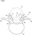
- the assumed rotation center of the vertebral body 51 to which the connection plate 3 is fixed is the center O of an imaginary circle D shown in FIG. 4 .
- This imaginary circle D is a circle assumed such that arc-shaped contour lines C of the concave portions of the intervertebral joints 53 substantially form parts of the circumference, when viewed from the head side of the human body.
- the contour line C of each intervertebral joint 53 is scarcely a mathematically complete arc.
- the arc-shaped contour line C substantially forms a part of the circumference and may not be completely matched with the circumference of the imaginary circle D.
- the center of the center hole 3d into which the center rod 4 is inserted is formed in the side surfaces of the connection plate 3 so that, in a state in which the connection plate 3 is fixed to the vertebral body 51, the center of the center hole 3d is on the back side of an imaginary line L1 which connects the middle points of the contour lines C of the neighboring intervertebral joints 53 when viewed from the head side of the human body.
- the middle point of the arc-shaped contour line C is a point P3 which is on the arc-shaped contour line C and is equally distanced from the both ends P1 and P2 of the contour line C.
- the above-described center of the hole may not be identical with the assumed rotation center (i.e., the center O of the imaginary circle D) of the vertebral body 51, but is on the back side of the vertebral body for which the center O of the imaginary circle D is assumed.
- the vertebral body 51 is therefore rotatable about the center rod 4 together with the connection plate 3, and hence the rotatability of the vertebral body 51 is less hindered.
- the rotational angle of each vertebra constituting the lumbar vertebrae is small, i.e., about 2 degrees. For this reason, even if the center of the center hole 3d is not completely identical with the center O of the imaginary circle D, the vertebral body 51 is rotatable and hence the rotatability of the vertebral body 51 is less hindered.
- the rotatability of the vertebral body 51 is further facilitated when, in a state that the connection plate 3 is fixed to the vertebral body 51, the center hole 3d into which the center rod 4 is inserted is formed in the side surfaces of the connection plate 3 so that the center hole 3d is positioned at the center O of the imaginary circle D, which is the assumed rotation center of the vertebral body 51 (i.e., the center of the center hole 3d is identical with the center O of the imaginary circle D).
- the shapes and sizes of the intervertebral joints 53 of each vertebra 50 are measured in three dimensions by CT or MRI, and the assumed rotation center of each vertebral body 51 is determined based on the measurement result.
- the center hole 3d is formed in the side surfaces of the connection plate 3 so that the center hole 3d is positioned at the determined rotation center.
- the center rod 4 is a member for connecting neighboring connection plates 3 which are fixed to the vertebral bodies 51 by the screws 1.
- the center rod 4 is preferably curved based on the data of the row of vertebrae 50 in an upright position.
- the data of the row of vertebrae 50 in the upright position is acquired by, for example, radiography.
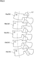
- FIG. 5 is a side view of the five vertebrae 50 (lumbar vertebrae 50a to 50e) constituting the spinal column in the upright position.
- An imaginary curve L2 shown in FIG. 5 connects the centers O of the imaginary circles D shown in FIG. 4 , in the direction in which the vertebrae 50 are lined up.
- the imaginary curve L2 connects the assumed rotation centers of the vertebral bodies 51, in the direction in which the vertebrae 50 are lined up.
- the center rod 4 is preferably curved along this imaginary curve L2.
- the depicted imaginary curve L2 penetrates the spinous processes. The spinous processes are removed in the surgery in order to allow the connection plates 3 to be fitted with the intervertebral joints 53.
- the shapes and sizes of the intervertebral joints 53 of each vertebra 50 are measured in three dimensions by CT or MRI, and the assumed rotation center of each vertebral body 51 is determined based on the measurement result.
- the imaginary curve L2 connects the assumed rotation centers of the vertebral bodies 51, in the direction in which the vertebrae 50 are lined up.
- the center rod 4 is preferably made of a material with a certain degree of flexibility, e.g., resin (plastic) such as PEEK resin and carbon fibers.
- resin plastic
- the flexibility (front/back flexibility) of the vertebral bodies 51 is less hindered.
- the spinal fusion implant 101 is used. To begin with, an operator cuts the back of the human body for a predetermined length so that the vertebrae 50 are exposed. Then the spinous processes are removed from implant-mounted part of the vertebrae 50. The vertebral arch 52 is typically not removed, but may be removed from the vertebra 50 according to need.
- connection plate 3 is closely attached to the back side of the vertebra 50 as the protrusions 8 of the connection plate 3 are fitted into the concave portions of the intervertebral joints 53.
- screws 1 are inserted into the guide holes 3c of the connection plate 3, and the screws 1 are screwed (punctured) into the vertebral body 51.
- the operator puts a lug wrench on the hexagonal prism part 1d at the rear end portion of the screw 1, and screws (punctures) the screw 1 into the vertebral body 51 along the guide hole 3c, by slowly rotating the lug wrench.
- connection plate 3 is fixed to the vertebra 50.
- the center rod 4 is inserted into the center holes 3d of the neighboring connection plates 3, so that the connection plates 3 are connected to one another.
- the center rod 4 is not fixed to the connection plates 3.
- a spinal fusion implant 102 of Second Embodiment of the present invention will be described with reference to FIG. 6 and FIG. 7 .
- members identical with those of the spinal fusion implant 101 of First Embodiment are denoted by the same reference symbols. (The same applies to later-described Third Embodiment.)
- the spinal fusion implant 102 of Second Embodiment is different from the spinal fusion implant 101 of First Embodiment in that, in the spinal fusion implant 102 of Second Embodiment, some of the connection plates are connected with one another by lateral rods 5, in addition to the center rod 4.
- the spinal fusion implant 102 includes three connection plates 3 provided in series, and two of these connection plates 3 are further connected with each other by lateral rods 5 which are provided on the respective sides of the center rod 4.
- connection plates where the lateral rods 5 are provided preference is given to the fixation of the vertebral bodies 51. Meanwhile, at the connection plate where the lateral rods 5 are not provided, preference is given to the rotatability of the vertebral bodies 51.
- the force of fixing the vertebral bodies 51 is partially enhanced by connecting some connection plates with one another by the lateral rods 5, in addition to the center rod 4. As such, the force of fixing each vertebral body 51 is changed depending on whether to use the lateral rods 5.
- a part where the rotatability of the vertebral bodies 51 is preferred and a part where the fixation of the vertebral bodies 51 is preferred can therefore coexist.
- the lateral rods 5 are provided at the respective end portions of the connection plates 3, and the lateral rods 5 are attached to the connection plates 3 by using pin members 7.
- Each pin member 7 is composed of a ring-shaped rod holding portion 7a into which the lateral rod 5 is inserted and a leg portion 7b into which the screw 1 is inserted.
- a nut 6 is tightened from the back side.
- the leg portion 7b is elastically deformed and the lateral rod 5 is gripped by the rod holding portion 7a.
- connection plate 3 may be connected to the lateral rods 5 in such a way that holes are bored in the side surfaces of the both end portions of the connection plate 3 and the lateral rods 5 are inserted into these holes.
- the connection plates 3 may or may not be fixed to the lateral rods 5. (The same applies to later-described Third Embodiment.)
- the spinal fusion implant 103 of Third Embodiment is different from the spinal fusion implant 102 of Second Embodiment in that, in the spinal fusion implant 103 of Third Embodiment, all of the connection plates are connected with one another by lateral rods 5 which are provided on the respective sides of the center rod 4.
- connection plates 3, the center rod 4, and the lateral rods 5 are made of a material with a certain degree of flexibility, e.g., resin (plastic) such as PEEK resin and carbon fibers.
- the spinal fusion implant 103 of the present embodiment is slightly inferior to the spinal fusion implant 101 shown in FIG. 1 , etc. having no lateral rods 5, in terms of the rotatability of the vertebral bodies 51.
- the main components are made of a resin material or a carbon fiber material, the rotatability of the vertebral bodies 51 is less hindered in the spinal fusion implant 103 of the present embodiment, too.
- the spinal fusion implant 103 of the present embodiment because two screws 1, a connection plate 3, and three rods (a center rod 4 and lateral rods 5) form a sort of frame structure, the vertebral bodies 51 are firmly fixed while the rotatability of the vertebral bodies 51 is less hindered. Furthermore, on account of the frame structure, a load on each component of the implant is distributed.
- the inventors of the subject application performed an experiment of attaching a prototype spinal fusion implant 103 shown in FIG. 9 to the vertebrae of a pig.
- the inventors screwed (punctured) screws 1 into the vertebral bodies 51 along the guide holes 3c of the connection plates 3 while closely attaching the protrusions 8 (see FIG. 2 ) of each connection plate 3 to the concave portions of the intervertebral joints of the pig.
- the screws 1 were fixed to the vertebral bodies 51 without the occurrence of erroneous screwing (erroneous puncture).
- FIG. 10 is a photograph showing a state in which a spinal fusion implant 104 made of PEEK resin has just been attached to the vertebrae of a pig with its back cut open.
- FIG. 11 and FIG. 12 are a CT image and an MRI image of the back portion of the pig in which the spinal fusion implant 104 is attached to the vertebrae (i.e., embedded in the body).
- connection plates 3 are connected to one another by lateral rods 5 in addition to the center rod 4 and one connection plate 3 is connected only by the center rod 4.
- This spinal fusion implant 104 is different from the spinal fusion implant 102 shown in FIG. 7 in the number of connection plates 3 connected by the lateral rods 5.
- FIG. 11 and FIG. 12 show that no artifact was observed in both the CT photography and the MRI photography because the spinal fusion implant 104 was made of a PEEK resin material. Furthermore, FIG. 11 and FIG. 12 show that the screws 1 are correctly punctured into the pedicles.
- connection plates 3 While in the embodiment above three or four connection plates 3 are used, the number of the connection plates 3 is not limited to three or four. The number of the connection plates 3 may be two, or may be five or more.
- lateral rods 5 are provided on the respective sides of the center rod 4, a lateral rod 5 may be provided on only one side of the center rod 4.
Landscapes
- Health & Medical Sciences (AREA)
- Orthopedic Medicine & Surgery (AREA)
- Life Sciences & Earth Sciences (AREA)
- Neurology (AREA)
- Surgery (AREA)
- Heart & Thoracic Surgery (AREA)
- Engineering & Computer Science (AREA)
- Biomedical Technology (AREA)
- Nuclear Medicine, Radiotherapy & Molecular Imaging (AREA)
- Medical Informatics (AREA)
- Molecular Biology (AREA)
- Animal Behavior & Ethology (AREA)
- General Health & Medical Sciences (AREA)
- Public Health (AREA)
- Veterinary Medicine (AREA)
- Surgical Instruments (AREA)
- Prostheses (AREA)
Abstract
Description
- The present invention relates to a spinal fusion implant which keeps the relative positions of neighboring vertebral bodies to fall within a predetermined range.
- An example of this technology is recited in
Patent Literature 1. A spinal fusion system recited inPatent Literature 1 includes screws fixed to vertebral bodies, which are regarded as fixing members, and rods connecting the screws with each other. As shown in, for example,FIG. 5 ofPatent Literature 1, two screws are screwed (punctured) into and fixed to a vertebral body in each vertebra. The relative positions of neighboring vertebral bodies are fixed by two groups of screws and rods, which are arranged to be in parallel. The document further recites that, in order to further firmly fix the vertebral bodies with each other, the neighboring rods may be connected to each other by a lateral connector. - Although not clearly recited in
Patent Literature 1, the screws, the rods, and the lateral connector are made of a metal material such as titanium. - [Patent Literature 1] Published Japanese Translation of a
PCT application No. 2006-523502 2006-523502 - The known spinal fusion implant recited in
Patent Literature 1 completely fixes the neighboring vertebral bodies to each other. Because the relative positions of the completely fixed vertebral bodies do not change at all, the rotation range of the waist of the patient is narrowed after the surgery, and it becomes difficult to rotate the waist. The daily life of the patient may therefore be affected after the surgery. Furthermore, a bone fracture may occur between the completely fixed vertebral body and a neighboring vertebral body which is not fixed. The rotational angle of five lumbar vertebrae (vertebrae) is typically about 10 degrees, and hence the rotational angle per each vertebral body is about 2 degrees. - In addition to the above, the known spinal fusion implant recited in
Patent Literature 1 involves the following problem. When an operator screws a screw into a vertebral body, erroneous screwing (erroneous puncture) occurs at a non-negligible rate (about 5 to 10%). In this regard, a spinal cord extends in a spinal canal which is between a vertebral body and a vertebral arch constituting a vertebra. The heart, various organs, the aorta, the vena cava, etc. are on the belly side of the vertebral bodies. When, for example, the spinal cord is damaged by erroneous screwing (erroneous puncture) of a screw, neuralgia or paralytic symptoms may occur. Furthermore, massive hemorrhage may occur when a large vessel such as the aorta is damaged. - In order to prevent the occurrence of erroneous screwing (erroneous puncture) of a screw into a vertebral body, some hospitals have three-dimensional monitoring systems (navigation systems) which are very expensive. However, not all hospitals are able to have such systems for various reasons.
- The present invention has been done under the circumference described above, and an object of the present invention is to provide a spinal fusion implant by which the rotatability of vertebral bodies is less hindered and erroneous screwing (erroneous puncture) of a screw is prevented.
- A spinal fusion implant provided by the present invention, which keeps relative positions of neighboring vertebral bodies to fall within a predetermined range, includes: screws connected to vertebral bodies; at least two connection plates in each of which guide holes into which the screws are inserted from a back side surface toward a belly side surface are formed at both end portions; and a center rod which connects neighboring ones of the connection plates which are fixed to the vertebral bodies by the screws. Each of the connection plates has, on the belly side surface, protrusions which are fitted into concave portions of intervertebral joints, and a center hole into which the center rod is slidably inserted is formed in side surfaces of each of the connection plates so that the center of the center hole is on the back side of an imaginary line which connects middle points of arc-shaped contour lines of the concave portions of the neighboring intervertebral joints when viewed from the head side of a human body.
- As described in The Physiology of the Joints written by I. A. Kapandji, which is renowned in the field of orthopedics, the assumed rotation center of a vertebral body is positioned at the center of an imaginary circle assumed from arc-shaped contour lines of the concave portions of the intervertebral joints when viewed from the head side of the human body. The center of the center hole into which the center rod is slidably inserted may not be identical with the assumed rotation center of the vertebral body, but the assumed rotation center of the vertebral body is on the back side of the vertebral body. The vertebral body is therefore rotatable about the center rod together with the connection plate, and hence the rotation of the vertebral body is less hindered.
In addition to the above, the connection plate has, on the belly side surface, the protrusions which are fitted into the concave portions of the intervertebral joints. This arrangement allows the connection plate to be closely in contact with the back side of the vertebra. This minimizes the rattling and deviation of the screw in screwing (puncture). Furthermore, as the protrusions of the connection plate are fitted into the concave portions of the intervertebral joints, the screwing positions and angles of the screws are correctly determined. As a result, the occurrence of erroneous screwing (erroneous puncture) is prevented as compared to conventional ones. Furthermore, because the belly side surface of the connection plate contributes to the integration of the vertebra and the connection plate, bone fracture of the vertebra is prevented while the rotatability of the vertebra is less hindered. - According to a preferred embodiment of the present invention, the center hole is positioned at the center of an imaginary circle which is assumed from the contour lines.
- This arrangement further facilitates the rotatability of the vertebral bodies.
- According to a preferred embodiment of the present invention, the center rod is curved based on data of a row of vertebrae in an upright position.
- This arrangement further facilitates the rotatability of the vertebral bodies when the patient is in an upright position, in particular when the patient is in action after the surgery.
- According to a preferred embodiment of the present invention, the center rod is curved along an imaginary curve which is formed by connecting centers of imaginary circles assumed from the contour lines, in a direction in which the vertebrae are lined up.
- This arrangement further facilitates the rotatability of the vertebral bodies.
- According to a preferred embodiment of the present invention, positions and angles of the guide holes in each of the connection plates are determined for each of the vertebral bodies so that the screws are accommodated inside the vertebral bodies.
- This arrangement prevents the spinal cord, the heart, the organs, or large vessels such as the aorta from being damaged by the screws, and the screws are screwed (punctured) more safely.
- According to a preferred embodiment of the present invention, the center rod is made of a resin material or a carbon fiber material.
- The resin material and the carbon fiber material have a certain degree of flexibility. For this reason, in addition to a lesser degree of hindrance to the rotatability of the vertebral bodies, the flexibility (front/back flexibility) of the vertebral bodies is less hindered.
- According to a preferred embodiment of the present invention, the screws, the connection plates, and the center rod are made of a resin material or a carbon fiber material.
- With this arrangement, in addition to a lesser degree of hindrance to the rotatability and flexibility of the vertebral bodies, the occurrence of an artifact which is a problem for metal implants is prevented.
- According to a preferred embodiment of the present invention, the spinal fusion implant further includes a lateral rod which is provided on either side of the center rod to connect neighboring ones of the connection plates, the lateral rod being made of a resin material or a carbon fiber material.
- With this arrangement, in addition to a lesser degree of hindrance to the rotatability of the vertebral bodies, the vertebral bodies are firmly fixed to one another.
- According to a preferred embodiment of the present invention, the number of the connection plates is three or more and the connection plates are lined up in series, and at least two of the connection plates are further connected with one another by lateral rods which are provided on the respective sides of the center rod.
- With this arrangement, a part where the rotatability of the vertebral bodies is preferred and a part where the fixation of the vertebral bodies is preferred can coexist.
- The present invention is able to provide a spinal fusion implant by which the rotatability of vertebral bodies is less hindered and erroneous screwing (erroneous puncture) of a screw is prevented.
-
-
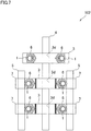
FIG. 1 is a perspective view of a spinal fusion implant of First Embodiment of the present invention. -
FIG. 2 is a front view of the spinal fusion implant shown inFIG. 1 , and shows a vertebra together with the spinal fusion implant. -
FIG. 3 is a front view of the spinal fusion implant shown inFIG. 1 (the vertebrae are not shown). -
FIG. 4 is provided for explaining the assumed rotation center of a vertebral body, and shows a state in which a vertebra (lumbar vertebra) from which the spinous process and the vertebral arch are removed is viewed from the head side of the human body. -
FIG. 5 is a side view of the five lumbar vertebrae constituting the spinal column in an upright position. -
FIG. 6 is a front view of a spinal fusion implant of Second Embodiment of the present invention, and shows a vertebra together with the spinal fusion implant. -
FIG. 7 is a front view of the spinal fusion implant shown inFIG. 6 (the vertebrae are not shown). -
FIG. 8 is a plan view of a spinal fusion implant of Third Embodiment of the present invention (no vertebrae are shown) . -
FIG. 9 is a photograph of a prototype of the spinal fusion implant shown inFIG. 8 . -
FIG. 10 is a photograph showing a state in which a spinal fusion implant made of PEEK resin has just been attached to the vertebrae of a pig with its back cut open. -
FIG. 11 is a CT image of the back portion of the pig in which the spinal fusion implant ofFIG. 10 is embedded. -
FIG. 12 is an MRI image of the back portion of the pig in which the spinal fusion implant ofFIG. 10 is embedded. - The following will describe an embodiment of the present invention with reference to figures.
- The structure of a
spinal fusion implant 101 of First Embodiment of the present invention will be described with reference toFIG. 1 to FIG. 5 . Thespinal fusion implant 101 is an implant which keeps the relative positions of neighboringvertebral bodies 51 to fall within a predetermined range, and main components of thisspinal fusion implant 101 areplural screws 1 fixed to thevertebral bodies 51, at least twoconnection plates 3, and acenter rod 4 connecting the neighboringconnection plates 3 with each other. - The phrase "keeping the relative positions of neighboring
vertebral bodies 51 to fall within a predetermined range" indicates that the implant of the present invention does not completely fix vertebral bodies as in the case of the known spinal fusion implant, and is a spinal fusion implant with which the movability of the vertebral bodies is less hindered. - The
screw 1 is a member by which theconnection plate 3 is fixed to avertebral body 51, and includes a taperedscrew part 1a, acylindrical part 1b, aparallel screw part 1c, and ahexagonal prism part 1d, which are provided in this order from the leading end side. Thescrew 1 is made of resin (plastic), carbon fibers, metal, or a composite of these materials. (The same applies to theconnection plates 3, thecenter rod 4, and later-describedlateral rods 5.) Examples of the resin material include PEEK resin (polyether ether ketone resin) and PLA resin (polylactic resin). Examples of the metal material include titanium, titanium alloy, cobalt - chromium alloy, and stainless steel. - The
connection plates 3 are members fixed to thevertebral bodies 51 by thescrews 1 and connect thevertebral bodies 51 which are adjacent to each other by means of thecenter rod 4. At the both end portions of theconnection plate 3, guideholes 3c are formed to allow thescrews 1 to be inserted from aback side surface 3a to abelly side surface 3b opposite to theback side surface 3a. - Furthermore, the
connection plate 3 has, on thebelly side surface 3b,protrusions 8 which are fitted into concave portions ofintervertebral joints 53. Avertebra 50 is formed of components such as avertebral body 51, avertebral arch 52,intervertebral joints 53,transverse processes 54,pedicles 55, and a spinous process. The spinous process has been removed from thevertebra 50 shown inFIG. 2 . The spinous process and thevertebral arch 52 have been removed from thevertebra 50 shown inFIG. 4 . Before screwing thescrew 1 into thevertebral body 51, the operator causes theprotrusions 8 of theconnection plate 3 to fit into the concave portions of the intervertebral joints 53. As a result of this, theconnection plate 3 is closely in contact with the back side of thevertebra 50. This minimizes the rattling and deviation of thescrew 1 in the subsequent screwing (puncture) . The positions and sizes of theprotrusions 8 on thebelly side surface 3b are preferably determined for eachvertebra 50. For example, before the surgery, the shape and size of eachvertebra 50 is measured in three dimensions by CT or MRI, and the positions and sizes of theprotrusions 8 on thebelly side surface 3b are determined in accordance with the concave portions of theintervertebral joints 53, in accordance with the measurement result. Then theconnection plate 3 is manufactured for eachvertebra 50. - The positions and angles of the guide holes 3c in the
connection plate 3 are preferably determined for eachvertebral body 51 so that eachtapered screw part 1a (screw 1) is accommodated inside the vertebral body 51 (seeFIG. 2 ) . As described above, for example, before the surgery, the shape and size of eachvertebra 50 is measured in three dimensions by CT or MRI, and the positions and angles of the guide holes 3c in theconnection plate 3 are determined to be optimal for each vertebral body so that eachtapered screw part 1a (screw 1) is accommodated inside thevertebral body 51, in accordance with the measurement result. This prevents the spinal cord, the heart, the organs, or large vessels such as the aorta from being damaged by thescrews 1, and thescrews 1 are screwed (punctured) more safely. - A
center hole 3d is formed in the side surfaces of theconnection plate 3. Thecenter rod 4 is slidably inserted into thiscenter hole 3d. Theconnection plates 3 and thecenter rod 4 are not completely fixed, and theconnection plates 3 are rotatable about thecenter rod 4. - Now, the following will describe the assumed rotation center of the
vertebral body 51 to which theconnection plate 3 is fixed, with reference toFIG. 4 . As described in The Physiology of the Joints above, it has been known that the assumed rotation center of avertebral body 51 is the center O of an imaginary circle D shown inFIG. 4 . - This imaginary circle D is a circle assumed such that arc-shaped contour lines C of the concave portions of the
intervertebral joints 53 substantially form parts of the circumference, when viewed from the head side of the human body. The contour line C of each intervertebral joint 53 is scarcely a mathematically complete arc. On this account, the arc-shaped contour line C substantially forms a part of the circumference and may not be completely matched with the circumference of the imaginary circle D. - In order to arrange the rotatability of the
vertebral body 51 to be less hindered, the center of thecenter hole 3d into which thecenter rod 4 is inserted is formed in the side surfaces of theconnection plate 3 so that, in a state in which theconnection plate 3 is fixed to thevertebral body 51, the center of thecenter hole 3d is on the back side of an imaginary line L1 which connects the middle points of the contour lines C of the neighboringintervertebral joints 53 when viewed from the head side of the human body. The middle point of the arc-shaped contour line C is a point P3 which is on the arc-shaped contour line C and is equally distanced from the both ends P1 and P2 of the contour line C. - The above-described center of the hole may not be identical with the assumed rotation center (i.e., the center O of the imaginary circle D) of the
vertebral body 51, but is on the back side of the vertebral body for which the center O of the imaginary circle D is assumed. Thevertebral body 51 is therefore rotatable about thecenter rod 4 together with theconnection plate 3, and hence the rotatability of thevertebral body 51 is less hindered. As described above, the rotational angle of each vertebra constituting the lumbar vertebrae is small, i.e., about 2 degrees. For this reason, even if the center of thecenter hole 3d is not completely identical with the center O of the imaginary circle D, thevertebral body 51 is rotatable and hence the rotatability of thevertebral body 51 is less hindered. - The rotatability of the
vertebral body 51 is further facilitated when, in a state that theconnection plate 3 is fixed to thevertebral body 51, thecenter hole 3d into which thecenter rod 4 is inserted is formed in the side surfaces of theconnection plate 3 so that thecenter hole 3d is positioned at the center O of the imaginary circle D, which is the assumed rotation center of the vertebral body 51 (i.e., the center of thecenter hole 3d is identical with the center O of the imaginary circle D). - Before the surgery, the shapes and sizes of the
intervertebral joints 53 of eachvertebra 50 are measured in three dimensions by CT or MRI, and the assumed rotation center of eachvertebral body 51 is determined based on the measurement result. In the state that theconnection plate 3 is fixed to thevertebral body 51, thecenter hole 3d is formed in the side surfaces of theconnection plate 3 so that thecenter hole 3d is positioned at the determined rotation center. - The
center rod 4 is a member for connecting neighboringconnection plates 3 which are fixed to thevertebral bodies 51 by thescrews 1. - In order to further facilitate the rotatability of the
vertebral bodies 51, thecenter rod 4 is preferably curved based on the data of the row ofvertebrae 50 in an upright position. The data of the row ofvertebrae 50 in the upright position is acquired by, for example, radiography. -
FIG. 5 is a side view of the five vertebrae 50 (lumbar vertebrae 50a to 50e) constituting the spinal column in the upright position. An imaginary curve L2 shown inFIG. 5 connects the centers O of the imaginary circles D shown inFIG. 4 , in the direction in which thevertebrae 50 are lined up. In other words, the imaginary curve L2 connects the assumed rotation centers of thevertebral bodies 51, in the direction in which thevertebrae 50 are lined up. Thecenter rod 4 is preferably curved along this imaginary curve L2. The depicted imaginary curve L2 penetrates the spinous processes. The spinous processes are removed in the surgery in order to allow theconnection plates 3 to be fitted with the intervertebral joints 53. - As described above, before the surgery, the shapes and sizes of the
intervertebral joints 53 of eachvertebra 50 are measured in three dimensions by CT or MRI, and the assumed rotation center of eachvertebral body 51 is determined based on the measurement result. The imaginary curve L2 connects the assumed rotation centers of thevertebral bodies 51, in the direction in which thevertebrae 50 are lined up. - In regard to the material, the
center rod 4 is preferably made of a material with a certain degree of flexibility, e.g., resin (plastic) such as PEEK resin and carbon fibers. With this arrangement, in addition to a lesser degree of hindrance to the rotatability of thevertebral bodies 51, the flexibility (front/back flexibility) of thevertebral bodies 51 is less hindered. - The following will describe how the
spinal fusion implant 101 is used. To begin with, an operator cuts the back of the human body for a predetermined length so that thevertebrae 50 are exposed. Then the spinous processes are removed from implant-mounted part of thevertebrae 50. Thevertebral arch 52 is typically not removed, but may be removed from thevertebra 50 according to need. - Subsequently, the
connection plate 3 is closely attached to the back side of thevertebra 50 as theprotrusions 8 of theconnection plate 3 are fitted into the concave portions of the intervertebral joints 53. Then thescrews 1 are inserted into the guide holes 3c of theconnection plate 3, and thescrews 1 are screwed (punctured) into thevertebral body 51. The operator puts a lug wrench on thehexagonal prism part 1d at the rear end portion of thescrew 1, and screws (punctures) thescrew 1 into thevertebral body 51 along theguide hole 3c, by slowly rotating the lug wrench. - After the screwing of the
screw 1 is completed, anut 6 is threaded onto theparallel screw part 1c of thescrew 1 from the back side, so that theconnection plate 3 is fixed to thevertebra 50. Subsequently, thecenter rod 4 is inserted into the center holes 3d of the neighboringconnection plates 3, so that theconnection plates 3 are connected to one another. - The
center rod 4 is not fixed to theconnection plates 3. Thecenter rod 4, however, hardly drops off from theconnection plates 3 on account of the spinous processes, etc. which are on the front and back of thecenter rod 4 in the axial direction. - The structure of a
spinal fusion implant 102 of Second Embodiment of the present invention will be described with reference toFIG. 6 andFIG. 7 . In thespinal fusion implant 102 of Second Embodiment, members identical with those of thespinal fusion implant 101 of First Embodiment are denoted by the same reference symbols. (The same applies to later-described Third Embodiment.) - The
spinal fusion implant 102 of Second Embodiment is different from thespinal fusion implant 101 of First Embodiment in that, in thespinal fusion implant 102 of Second Embodiment, some of the connection plates are connected with one another bylateral rods 5, in addition to thecenter rod 4. - The
spinal fusion implant 102 includes threeconnection plates 3 provided in series, and two of theseconnection plates 3 are further connected with each other bylateral rods 5 which are provided on the respective sides of thecenter rod 4. - At the connection plates where the
lateral rods 5 are provided, preference is given to the fixation of thevertebral bodies 51. Meanwhile, at the connection plate where thelateral rods 5 are not provided, preference is given to the rotatability of thevertebral bodies 51. In this way, the force of fixing thevertebral bodies 51 is partially enhanced by connecting some connection plates with one another by thelateral rods 5, in addition to thecenter rod 4. As such, the force of fixing eachvertebral body 51 is changed depending on whether to use thelateral rods 5. A part where the rotatability of thevertebral bodies 51 is preferred and a part where the fixation of thevertebral bodies 51 is preferred can therefore coexist. - In the present embodiment, the
lateral rods 5 are provided at the respective end portions of theconnection plates 3, and thelateral rods 5 are attached to theconnection plates 3 by usingpin members 7. Eachpin member 7 is composed of a ring-shapedrod holding portion 7a into which thelateral rod 5 is inserted and aleg portion 7b into which thescrew 1 is inserted. In a state in which thelateral rod 5 is inserted into therod holding portion 7a and thescrew 1 is inserted into theleg portion 7b, anut 6 is tightened from the back side. As a result, theleg portion 7b is elastically deformed and thelateral rod 5 is gripped by therod holding portion 7a. - Alternatively, being similar to the attachment of the
center rod 4 to theconnection plate 3, theconnection plate 3 may be connected to thelateral rods 5 in such a way that holes are bored in the side surfaces of the both end portions of theconnection plate 3 and thelateral rods 5 are inserted into these holes. Theconnection plates 3 may or may not be fixed to thelateral rods 5. (The same applies to later-described Third Embodiment.) - The structure of a
spinal fusion implant 103 of Third Embodiment of the present invention will be described with reference toFIG. 8 andFIG. 9 . - The
spinal fusion implant 103 of Third Embodiment is different from thespinal fusion implant 102 of Second Embodiment in that, in thespinal fusion implant 103 of Third Embodiment, all of the connection plates are connected with one another bylateral rods 5 which are provided on the respective sides of thecenter rod 4. - In this arrangement, in order to maintain the rotatability of the
vertebral bodies 51, at least theconnection plates 3, thecenter rod 4, and thelateral rods 5 are made of a material with a certain degree of flexibility, e.g., resin (plastic) such as PEEK resin and carbon fibers. Thespinal fusion implant 103 of the present embodiment is slightly inferior to thespinal fusion implant 101 shown inFIG. 1 , etc. having nolateral rods 5, in terms of the rotatability of thevertebral bodies 51. However, because the main components are made of a resin material or a carbon fiber material, the rotatability of thevertebral bodies 51 is less hindered in thespinal fusion implant 103 of the present embodiment, too. - In the
spinal fusion implant 103 of the present embodiment, because twoscrews 1, aconnection plate 3, and three rods (acenter rod 4 and lateral rods 5) form a sort of frame structure, thevertebral bodies 51 are firmly fixed while the rotatability of thevertebral bodies 51 is less hindered. Furthermore, on account of the frame structure, a load on each component of the implant is distributed. - In the
spinal fusion implant 103 which is a prototype and shown inFIG. 9 , all of thescrews 1, theconnection plates 3, thecenter rod 4, thelateral rods 5, thenuts 6, and thepin members 7 are made of PEEK resin. In this connection, because an artifact appears around the spine fixed by a metal implant during MRI or CT photography, it is difficult to grasp the state of spinal neoplasm or a state of fusion of a grafted bone. When the components are made of a resin material or a carbon fiber material as in thespinal fusion implant 103 of the present embodiment, it is possible to prevent the occurrence of an artifact. - The inventors of the subject application performed an experiment of attaching a prototype
spinal fusion implant 103 shown inFIG. 9 to the vertebrae of a pig. The inventors screwed (punctured) screws 1 into thevertebral bodies 51 along the guide holes 3c of theconnection plates 3 while closely attaching the protrusions 8 (seeFIG. 2 ) of eachconnection plate 3 to the concave portions of the intervertebral joints of the pig. As a result, thescrews 1 were fixed to thevertebral bodies 51 without the occurrence of erroneous screwing (erroneous puncture). After the connection of theconnection plates 3 by thecenter rod 4 and thelateral rods 5, the rotatability of the vertebral bodies were confirmed by a hand. -
FIG. 10 is a photograph showing a state in which aspinal fusion implant 104 made of PEEK resin has just been attached to the vertebrae of a pig with its back cut open.FIG. 11 andFIG. 12 are a CT image and an MRI image of the back portion of the pig in which thespinal fusion implant 104 is attached to the vertebrae (i.e., embedded in the body). - In the
spinal fusion implant 104, threeconnection plates 3 are connected to one another bylateral rods 5 in addition to thecenter rod 4 and oneconnection plate 3 is connected only by thecenter rod 4. Thisspinal fusion implant 104 is different from thespinal fusion implant 102 shown inFIG. 7 in the number ofconnection plates 3 connected by thelateral rods 5. - As shown in
FIG. 11 andFIG. 12 , no artifact was observed in both the CT photography and the MRI photography because thespinal fusion implant 104 was made of a PEEK resin material. Furthermore,FIG. 11 andFIG. 12 show that thescrews 1 are correctly punctured into the pedicles. - While in the embodiment above three or four
connection plates 3 are used, the number of theconnection plates 3 is not limited to three or four. The number of theconnection plates 3 may be two, or may be five or more. - While in the
spinal fusion implants FIG. 6 to FIG. 12 thelateral rods 5 are provided on the respective sides of thecenter rod 4, alateral rod 5 may be provided on only one side of thecenter rod 4. - The embodiments of the present invention and their modifications have been described. It is a matter of course that other changes or alterations can be made on the present invention within the scope of envisagement of one skilled in the art.
-
- 1: screw
- 3: connection plate
- 3a: back side surface
- 3b: belly side surface
- 3c: guide hole
- 3d: center hole
- 4: center rod
- 5: lateral rod
- 8: protrusion
- 50: vertebra
- 51: vertebral body
- 53: intervertebral joint
- C: arc-shaped contour line of concave portion of intervertebral joint
- D: imaginary circle
- O: center of imaginary circle (rotation center)
- L1: imaginary line
- L2: imaginary curve
- 101, 102, 103, 104: spinal fusion implant
Claims (9)
- A spinal fusion implant which keeps relative positions of neighboring vertebral bodies to fall within a predetermined range, comprising:screws connected to vertebral bodies;at least two connection plates in each of which guide holes into which the screws are inserted from a back side surface toward a belly side surface are formed at both end portions; anda center rod which connects neighboring ones of the connection plates which are fixed to the vertebral bodies by the screws, each of the connection plates having, on the belly side surface, protrusions which are fitted into concave portions of intervertebral joints, anda center hole into which the center rod is slidably inserted being formed in side surfaces of each of the connection plates so that the center of the center hole is on the back side of an imaginary line which connects middle points of arc-shaped contour lines of the concave portions of the neighboring intervertebral joints when viewed from the head side of a human body.
- The spinal fusion implant according to claim 1, wherein,
the center hole is positioned at the center of an imaginary circle which is assumed from the contour lines. - The spinal fusion implant according to claim 1 or 2, wherein,
the center rod is curved based on data of a row of vertebrae in an upright position. - The spinal fusion implant according to claim 3, wherein,
the center rod is curved along an imaginary curve which is formed by connecting centers of imaginary circles assumed from the contour lines, in a direction in which the vertebrae are lined up. - The spinal fusion implant according to any one of claims 1 to 4, wherein,
positions and angles of the guide holes in each of the connection plates are determined for each of the vertebral bodies so that the screws are accommodated inside the vertebral bodies. - The spinal fusion implant according to any one of claims 1 to 5, wherein,
the center rod is made of a resin material or a carbon fiber material. - The spinal fusion implant according to any one of claims 1 to 6, wherein,
the screws, the connection plates, and the center rod are made of a resin material or a carbon fiber material. - The spinal fusion implant according to claim 7, further comprising
a lateral rod which is provided on either side of the center rod to connect neighboring ones of the connection plates,
the lateral rod being made of a resin material or a carbon fiber material. - The spinal fusion implant according to any one of claims 1 to 7, wherein,
the number of the connection plates is three or more and the connection plates are lined up in series, and
at least two of the connection plates are further connected with one another by lateral rods which are provided on the respective sides of the center rod.
Applications Claiming Priority (2)
| Application Number | Priority Date | Filing Date | Title |
|---|---|---|---|
| JP2017113495 | 2017-06-08 | ||
| PCT/JP2018/020636 WO2018225588A1 (en) | 2017-06-08 | 2018-05-30 | Spinal fusion implant |
Publications (3)
| Publication Number | Publication Date |
|---|---|
| EP3636186A1 true EP3636186A1 (en) | 2020-04-15 |
| EP3636186A4 EP3636186A4 (en) | 2021-03-24 |
| EP3636186B1 EP3636186B1 (en) | 2024-09-04 |
Family
ID=64566119
Family Applications (1)
| Application Number | Title | Priority Date | Filing Date |
|---|---|---|---|
| EP18814248.3A Active EP3636186B1 (en) | 2017-06-08 | 2018-05-30 | Spinal fusion implant |
Country Status (4)
| Country | Link |
|---|---|
| US (1) | US11478279B2 (en) |
| EP (1) | EP3636186B1 (en) |
| JP (1) | JP7226802B2 (en) |
| WO (1) | WO2018225588A1 (en) |
Cited By (1)
| Publication number | Priority date | Publication date | Assignee | Title |
|---|---|---|---|---|
| CN113229915A (en) * | 2021-04-21 | 2021-08-10 | 天津市金兴达实业有限公司 | Intramedullary pin |
Families Citing this family (1)
| Publication number | Priority date | Publication date | Assignee | Title |
|---|---|---|---|---|
| CN112137671A (en) * | 2019-06-27 | 2020-12-29 | 青岛大学附属医院 | Percutaneous pedicle screw-assisted expandable hemostasis conical device |
Family Cites Families (22)
| Publication number | Priority date | Publication date | Assignee | Title |
|---|---|---|---|---|
| US5306275A (en) * | 1992-12-31 | 1994-04-26 | Bryan Donald W | Lumbar spine fixation apparatus and method |
| US6293949B1 (en) * | 2000-03-01 | 2001-09-25 | Sdgi Holdings, Inc. | Superelastic spinal stabilization system and method |
| JP2002000611A (en) * | 2000-05-12 | 2002-01-08 | Sulzer Orthopedics Ltd | Bone screw to be joined with the bone plate |
| US6458131B1 (en) * | 2000-08-07 | 2002-10-01 | Salut, Ltd. | Apparatus and method for reducing spinal deformity |
| US7220262B1 (en) * | 2001-03-16 | 2007-05-22 | Sdgi Holdings, Inc. | Spinal fixation system and related methods |
| US20040210216A1 (en) | 2003-04-17 | 2004-10-21 | Farris Robert A | Spinal fixation system and method |
| US7377942B2 (en) * | 2003-08-06 | 2008-05-27 | Warsaw Orthopedic, Inc. | Posterior elements motion restoring device |
| US8333789B2 (en) * | 2007-01-10 | 2012-12-18 | Gmedelaware 2 Llc | Facet joint replacement |
| EP1758511A4 (en) * | 2004-06-14 | 2008-12-03 | M S Abdou | Occipital fixation system and method of use |
| US20070185489A1 (en) * | 2006-01-26 | 2007-08-09 | Abdou M S | Devices and Methods for Inter-Vertebral Orthopedic Device Placement |
| US20080021454A1 (en) * | 2006-07-21 | 2008-01-24 | Depuy Spine, Inc. | Sacral or iliac connector |
| US8361117B2 (en) * | 2006-11-08 | 2013-01-29 | Depuy Spine, Inc. | Spinal cross connectors |
| WO2009155360A2 (en) | 2008-06-20 | 2009-12-23 | Neil Duggal | Systems and methods for posterior dynamic stabilization |
| US8740951B2 (en) * | 2008-09-04 | 2014-06-03 | Bullard Spine, Llc | Anterior cervical instrumentation systems, methods and devices |
| US8623062B2 (en) | 2008-09-29 | 2014-01-07 | Dimitriy G. Kondrashov | System and method to stablize a spinal column including a spinolaminar locking plate |
| GB0822507D0 (en) * | 2008-12-10 | 2009-01-14 | Karnezis Ioannis | Surgical device for correction of spinal deformities |
| TWI388308B (en) * | 2009-12-31 | 2013-03-11 | Ind Tech Res Inst | Flexible spinal fixation |
| US9283001B2 (en) * | 2012-01-18 | 2016-03-15 | Globus Medical, Inc. | Systems for spinal stabilization |
| KR101584359B1 (en) * | 2013-12-09 | 2016-01-25 | (주)메디쎄이 | Implant for laminoplasty and apparatus at the rear of Spinal |
| US9763705B2 (en) * | 2014-10-03 | 2017-09-19 | Globus Medical, Inc. | Orthopedic stabilization devices and methods for installation thereof |
| US9615931B2 (en) * | 2015-03-20 | 2017-04-11 | Globus Medical, Inc. | Surgical plate systems |
| US9717541B2 (en) * | 2015-04-13 | 2017-08-01 | DePuy Synthes Products, Inc. | Lamina implants and methods for spinal decompression |
-
2018
- 2018-05-30 WO PCT/JP2018/020636 patent/WO2018225588A1/en not_active Ceased
- 2018-05-30 US US16/620,138 patent/US11478279B2/en active Active
- 2018-05-30 JP JP2019523475A patent/JP7226802B2/en active Active
- 2018-05-30 EP EP18814248.3A patent/EP3636186B1/en active Active
Cited By (2)
| Publication number | Priority date | Publication date | Assignee | Title |
|---|---|---|---|---|
| CN113229915A (en) * | 2021-04-21 | 2021-08-10 | 天津市金兴达实业有限公司 | Intramedullary pin |
| CN113229915B (en) * | 2021-04-21 | 2022-12-13 | 天津市金兴达实业有限公司 | Intramedullary pin |
Also Published As
| Publication number | Publication date |
|---|---|
| US11478279B2 (en) | 2022-10-25 |
| EP3636186A4 (en) | 2021-03-24 |
| WO2018225588A1 (en) | 2018-12-13 |
| US20200197047A1 (en) | 2020-06-25 |
| EP3636186B1 (en) | 2024-09-04 |
| JP7226802B2 (en) | 2023-02-21 |
| JPWO2018225588A1 (en) | 2020-04-09 |
Similar Documents
| Publication | Publication Date | Title |
|---|---|---|
| US20200352606A1 (en) | Rod and anchor system and method for using | |
| US8663295B2 (en) | Posterior spinal prosthesis | |
| US8317843B2 (en) | Multi-axis connection and methods for internal spinal stabilizers | |
| US9144506B2 (en) | Interbody axis cage | |
| EP1729664B1 (en) | Head-to-head connector spinal fixation system | |
| US9517089B1 (en) | Bone anchor with offset rod connector | |
| EP1638472A1 (en) | Vertebral osteosynthesis equipment | |
| US8591551B2 (en) | Linked spinal stabilization elements for spinal fixation | |
| US20070123860A1 (en) | Dorsal adjusting multi-rod connector | |
| EP0874594A1 (en) | Device for linking adjacent rods in spinal instrumentation | |
| JP2011041823A (en) | Upper part fixing system used for implantation rod, and implantation rod system using the system | |
| EP2088966A1 (en) | Pedicle dynamic facet arthroplasty system and method | |
| US12042183B2 (en) | Integral double rod spinal construct | |
| US20130190772A1 (en) | Elastic Guide Wire for Spinal Surgery | |
| US11478279B2 (en) | Spinal fusion implant | |
| US9962191B2 (en) | Spinal implant and methods of use thereof | |
| US11147595B2 (en) | Occipital plate with angled screw opening | |
| Vihar et al. | Comparative study of long segment versus short segment posterior fixation of thoracolumbar fractures with pedicle screws | |
| EP3419536B1 (en) | Integral double rod spinal construct | |
| Chin et al. | Biomechanical Comparison of Same Size Transfacet Screws Versus Pedicle Screws Across the L5-S1 Native Disc | |
| WO2018181895A1 (en) | Interspinous process implant | |
| KR101684345B1 (en) | Replacement device for replacing a centrum and fixing a sacrum implant | |
| US11707303B2 (en) | Multi-level vertebral implant system | |
| EP2363086A9 (en) | Transpedicular reduction screw | |
| Akhaddar | Polyaxial pedicle screw dislocation during screw tightening for posterior spinal lumbar stabilization |
Legal Events
| Date | Code | Title | Description |
|---|---|---|---|
| STAA | Information on the status of an ep patent application or granted ep patent |
Free format text: STATUS: THE INTERNATIONAL PUBLICATION HAS BEEN MADE |
|
| PUAI | Public reference made under article 153(3) epc to a published international application that has entered the european phase |
Free format text: ORIGINAL CODE: 0009012 |
|
| STAA | Information on the status of an ep patent application or granted ep patent |
Free format text: STATUS: REQUEST FOR EXAMINATION WAS MADE |
|
| 17P | Request for examination filed |
Effective date: 20200103 |
|
| AK | Designated contracting states |
Kind code of ref document: A1 Designated state(s): AL AT BE BG CH CY CZ DE DK EE ES FI FR GB GR HR HU IE IS IT LI LT LU LV MC MK MT NL NO PL PT RO RS SE SI SK SM TR |
|
| AX | Request for extension of the european patent |
Extension state: BA ME |
|
| DAV | Request for validation of the european patent (deleted) | ||
| DAX | Request for extension of the european patent (deleted) | ||
| A4 | Supplementary search report drawn up and despatched |
Effective date: 20210224 |
|
| RIC1 | Information provided on ipc code assigned before grant |
Ipc: A61B 17/56 20060101ALI20210218BHEP Ipc: A61B 17/70 20060101AFI20210218BHEP |
|
| STAA | Information on the status of an ep patent application or granted ep patent |
Free format text: STATUS: EXAMINATION IS IN PROGRESS |
|
| 17Q | First examination report despatched |
Effective date: 20230406 |
|
| P01 | Opt-out of the competence of the unified patent court (upc) registered |
Effective date: 20230414 |
|
| GRAP | Despatch of communication of intention to grant a patent |
Free format text: ORIGINAL CODE: EPIDOSNIGR1 |
|
| STAA | Information on the status of an ep patent application or granted ep patent |
Free format text: STATUS: GRANT OF PATENT IS INTENDED |
|
| INTG | Intention to grant announced |
Effective date: 20240426 |
|
| GRAS | Grant fee paid |
Free format text: ORIGINAL CODE: EPIDOSNIGR3 |
|
| GRAA | (expected) grant |
Free format text: ORIGINAL CODE: 0009210 |
|
| STAA | Information on the status of an ep patent application or granted ep patent |
Free format text: STATUS: THE PATENT HAS BEEN GRANTED |
|
| AK | Designated contracting states |
Kind code of ref document: B1 Designated state(s): AL AT BE BG CH CY CZ DE DK EE ES FI FR GB GR HR HU IE IS IT LI LT LU LV MC MK MT NL NO PL PT RO RS SE SI SK SM TR |
|
| REG | Reference to a national code |
Ref country code: GB Ref legal event code: FG4D |
|
| REG | Reference to a national code |
Ref country code: CH Ref legal event code: EP |
|
| REG | Reference to a national code |
Ref country code: IE Ref legal event code: FG4D |
|
| REG | Reference to a national code |
Ref country code: DE Ref legal event code: R096 Ref document number: 602018074034 Country of ref document: DE |
|
| REG | Reference to a national code |
Ref country code: LT Ref legal event code: MG9D |
|
| REG | Reference to a national code |
Ref country code: NL Ref legal event code: MP Effective date: 20240904 |
|
| PG25 | Lapsed in a contracting state [announced via postgrant information from national office to epo] |
Ref country code: NO Free format text: LAPSE BECAUSE OF FAILURE TO SUBMIT A TRANSLATION OF THE DESCRIPTION OR TO PAY THE FEE WITHIN THE PRESCRIBED TIME-LIMIT Effective date: 20241204 |
|
| PG25 | Lapsed in a contracting state [announced via postgrant information from national office to epo] |
Ref country code: PL Free format text: LAPSE BECAUSE OF FAILURE TO SUBMIT A TRANSLATION OF THE DESCRIPTION OR TO PAY THE FEE WITHIN THE PRESCRIBED TIME-LIMIT Effective date: 20240904 Ref country code: GR Free format text: LAPSE BECAUSE OF FAILURE TO SUBMIT A TRANSLATION OF THE DESCRIPTION OR TO PAY THE FEE WITHIN THE PRESCRIBED TIME-LIMIT Effective date: 20241205 Ref country code: FI Free format text: LAPSE BECAUSE OF FAILURE TO SUBMIT A TRANSLATION OF THE DESCRIPTION OR TO PAY THE FEE WITHIN THE PRESCRIBED TIME-LIMIT Effective date: 20240904 |
|
| PG25 | Lapsed in a contracting state [announced via postgrant information from national office to epo] |
Ref country code: BG Free format text: LAPSE BECAUSE OF FAILURE TO SUBMIT A TRANSLATION OF THE DESCRIPTION OR TO PAY THE FEE WITHIN THE PRESCRIBED TIME-LIMIT Effective date: 20240904 |
|
| PG25 | Lapsed in a contracting state [announced via postgrant information from national office to epo] |
Ref country code: LV Free format text: LAPSE BECAUSE OF FAILURE TO SUBMIT A TRANSLATION OF THE DESCRIPTION OR TO PAY THE FEE WITHIN THE PRESCRIBED TIME-LIMIT Effective date: 20240904 |
|
| PG25 | Lapsed in a contracting state [announced via postgrant information from national office to epo] |
Ref country code: HR Free format text: LAPSE BECAUSE OF FAILURE TO SUBMIT A TRANSLATION OF THE DESCRIPTION OR TO PAY THE FEE WITHIN THE PRESCRIBED TIME-LIMIT Effective date: 20240904 |
|
| PG25 | Lapsed in a contracting state [announced via postgrant information from national office to epo] |
Ref country code: ES Free format text: LAPSE BECAUSE OF FAILURE TO SUBMIT A TRANSLATION OF THE DESCRIPTION OR TO PAY THE FEE WITHIN THE PRESCRIBED TIME-LIMIT Effective date: 20240904 Ref country code: RS Free format text: LAPSE BECAUSE OF FAILURE TO SUBMIT A TRANSLATION OF THE DESCRIPTION OR TO PAY THE FEE WITHIN THE PRESCRIBED TIME-LIMIT Effective date: 20241204 |
|
| PG25 | Lapsed in a contracting state [announced via postgrant information from national office to epo] |
Ref country code: RS Free format text: LAPSE BECAUSE OF FAILURE TO SUBMIT A TRANSLATION OF THE DESCRIPTION OR TO PAY THE FEE WITHIN THE PRESCRIBED TIME-LIMIT Effective date: 20241204 Ref country code: PL Free format text: LAPSE BECAUSE OF FAILURE TO SUBMIT A TRANSLATION OF THE DESCRIPTION OR TO PAY THE FEE WITHIN THE PRESCRIBED TIME-LIMIT Effective date: 20240904 Ref country code: NO Free format text: LAPSE BECAUSE OF FAILURE TO SUBMIT A TRANSLATION OF THE DESCRIPTION OR TO PAY THE FEE WITHIN THE PRESCRIBED TIME-LIMIT Effective date: 20241204 Ref country code: LV Free format text: LAPSE BECAUSE OF FAILURE TO SUBMIT A TRANSLATION OF THE DESCRIPTION OR TO PAY THE FEE WITHIN THE PRESCRIBED TIME-LIMIT Effective date: 20240904 Ref country code: HR Free format text: LAPSE BECAUSE OF FAILURE TO SUBMIT A TRANSLATION OF THE DESCRIPTION OR TO PAY THE FEE WITHIN THE PRESCRIBED TIME-LIMIT Effective date: 20240904 Ref country code: GR Free format text: LAPSE BECAUSE OF FAILURE TO SUBMIT A TRANSLATION OF THE DESCRIPTION OR TO PAY THE FEE WITHIN THE PRESCRIBED TIME-LIMIT Effective date: 20241205 Ref country code: FI Free format text: LAPSE BECAUSE OF FAILURE TO SUBMIT A TRANSLATION OF THE DESCRIPTION OR TO PAY THE FEE WITHIN THE PRESCRIBED TIME-LIMIT Effective date: 20240904 Ref country code: ES Free format text: LAPSE BECAUSE OF FAILURE TO SUBMIT A TRANSLATION OF THE DESCRIPTION OR TO PAY THE FEE WITHIN THE PRESCRIBED TIME-LIMIT Effective date: 20240904 Ref country code: BG Free format text: LAPSE BECAUSE OF FAILURE TO SUBMIT A TRANSLATION OF THE DESCRIPTION OR TO PAY THE FEE WITHIN THE PRESCRIBED TIME-LIMIT Effective date: 20240904 |
|
| REG | Reference to a national code |
Ref country code: AT Ref legal event code: MK05 Ref document number: 1719558 Country of ref document: AT Kind code of ref document: T Effective date: 20240904 |
|
| PG25 | Lapsed in a contracting state [announced via postgrant information from national office to epo] |
Ref country code: NL Free format text: LAPSE BECAUSE OF FAILURE TO SUBMIT A TRANSLATION OF THE DESCRIPTION OR TO PAY THE FEE WITHIN THE PRESCRIBED TIME-LIMIT Effective date: 20240904 |
|
| PG25 | Lapsed in a contracting state [announced via postgrant information from national office to epo] |
Ref country code: PT Free format text: LAPSE BECAUSE OF FAILURE TO SUBMIT A TRANSLATION OF THE DESCRIPTION OR TO PAY THE FEE WITHIN THE PRESCRIBED TIME-LIMIT Effective date: 20250106 Ref country code: IS Free format text: LAPSE BECAUSE OF FAILURE TO SUBMIT A TRANSLATION OF THE DESCRIPTION OR TO PAY THE FEE WITHIN THE PRESCRIBED TIME-LIMIT Effective date: 20250104 |
|
| PG25 | Lapsed in a contracting state [announced via postgrant information from national office to epo] |
Ref country code: SM Free format text: LAPSE BECAUSE OF FAILURE TO SUBMIT A TRANSLATION OF THE DESCRIPTION OR TO PAY THE FEE WITHIN THE PRESCRIBED TIME-LIMIT Effective date: 20240904 Ref country code: RO Free format text: LAPSE BECAUSE OF FAILURE TO SUBMIT A TRANSLATION OF THE DESCRIPTION OR TO PAY THE FEE WITHIN THE PRESCRIBED TIME-LIMIT Effective date: 20240904 |
|
| PG25 | Lapsed in a contracting state [announced via postgrant information from national office to epo] |
Ref country code: EE Free format text: LAPSE BECAUSE OF FAILURE TO SUBMIT A TRANSLATION OF THE DESCRIPTION OR TO PAY THE FEE WITHIN THE PRESCRIBED TIME-LIMIT Effective date: 20240904 Ref country code: AT Free format text: LAPSE BECAUSE OF FAILURE TO SUBMIT A TRANSLATION OF THE DESCRIPTION OR TO PAY THE FEE WITHIN THE PRESCRIBED TIME-LIMIT Effective date: 20240904 |
|
| PG25 | Lapsed in a contracting state [announced via postgrant information from national office to epo] |
Ref country code: CZ Free format text: LAPSE BECAUSE OF FAILURE TO SUBMIT A TRANSLATION OF THE DESCRIPTION OR TO PAY THE FEE WITHIN THE PRESCRIBED TIME-LIMIT Effective date: 20240904 |
|
| PG25 | Lapsed in a contracting state [announced via postgrant information from national office to epo] |
Ref country code: IT Free format text: LAPSE BECAUSE OF FAILURE TO SUBMIT A TRANSLATION OF THE DESCRIPTION OR TO PAY THE FEE WITHIN THE PRESCRIBED TIME-LIMIT Effective date: 20240904 Ref country code: SK Free format text: LAPSE BECAUSE OF FAILURE TO SUBMIT A TRANSLATION OF THE DESCRIPTION OR TO PAY THE FEE WITHIN THE PRESCRIBED TIME-LIMIT Effective date: 20240904 |
|
| REG | Reference to a national code |
Ref country code: DE Ref legal event code: R097 Ref document number: 602018074034 Country of ref document: DE |
|
| PGFP | Annual fee paid to national office [announced via postgrant information from national office to epo] |
Ref country code: DE Payment date: 20250520 Year of fee payment: 8 |
|
| PG25 | Lapsed in a contracting state [announced via postgrant information from national office to epo] |
Ref country code: DK Free format text: LAPSE BECAUSE OF FAILURE TO SUBMIT A TRANSLATION OF THE DESCRIPTION OR TO PAY THE FEE WITHIN THE PRESCRIBED TIME-LIMIT Effective date: 20240904 |
|
| PLBE | No opposition filed within time limit |
Free format text: ORIGINAL CODE: 0009261 |
|
| STAA | Information on the status of an ep patent application or granted ep patent |
Free format text: STATUS: NO OPPOSITION FILED WITHIN TIME LIMIT |
|
| PGFP | Annual fee paid to national office [announced via postgrant information from national office to epo] |
Ref country code: FR Payment date: 20250522 Year of fee payment: 8 |
|
| 26N | No opposition filed |
Effective date: 20250605 |
|
| PG25 | Lapsed in a contracting state [announced via postgrant information from national office to epo] |
Ref country code: SE Free format text: LAPSE BECAUSE OF FAILURE TO SUBMIT A TRANSLATION OF THE DESCRIPTION OR TO PAY THE FEE WITHIN THE PRESCRIBED TIME-LIMIT Effective date: 20240904 |
|
| REG | Reference to a national code |
Ref country code: CH Ref legal event code: H13 Free format text: ST27 STATUS EVENT CODE: U-0-0-H10-H13 (AS PROVIDED BY THE NATIONAL OFFICE) Effective date: 20251223 |
|
| PG25 | Lapsed in a contracting state [announced via postgrant information from national office to epo] |
Ref country code: LU Free format text: LAPSE BECAUSE OF NON-PAYMENT OF DUE FEES Effective date: 20250530 |
|
| PG25 | Lapsed in a contracting state [announced via postgrant information from national office to epo] |
Ref country code: CH Free format text: LAPSE BECAUSE OF NON-PAYMENT OF DUE FEES Effective date: 20250531 |
|
| REG | Reference to a national code |
Ref country code: BE Ref legal event code: MM Effective date: 20250531 |
|
| PG25 | Lapsed in a contracting state [announced via postgrant information from national office to epo] |
Ref country code: MC Free format text: LAPSE BECAUSE OF FAILURE TO SUBMIT A TRANSLATION OF THE DESCRIPTION OR TO PAY THE FEE WITHIN THE PRESCRIBED TIME-LIMIT Effective date: 20240904 |
|
| PGFP | Annual fee paid to national office [announced via postgrant information from national office to epo] |
Ref country code: GB Payment date: 20260330 Year of fee payment: 9 |
|
| PG25 | Lapsed in a contracting state [announced via postgrant information from national office to epo] |
Ref country code: IE Free format text: LAPSE BECAUSE OF NON-PAYMENT OF DUE FEES Effective date: 20250530 |
|
| PG25 | Lapsed in a contracting state [announced via postgrant information from national office to epo] |
Ref country code: BE Free format text: LAPSE BECAUSE OF NON-PAYMENT OF DUE FEES Effective date: 20250531 |
|
| REG | Reference to a national code |
Ref country code: DE Ref legal event code: R081 Ref document number: 602018074034 Country of ref document: DE Owner name: IWATE MEDICAL UNIVERSITY, JP Free format text: FORMER OWNER: NATIONAL UNIVERSITY CORPORATION KOBE UNIVERSITY, KOBE-SHI, HYOGO, JP |