EP3636167A1 - Apparatus for endoscopic procedures - Google Patents
Apparatus for endoscopic procedures Download PDFInfo
- Publication number
- EP3636167A1 EP3636167A1 EP19202762.1A EP19202762A EP3636167A1 EP 3636167 A1 EP3636167 A1 EP 3636167A1 EP 19202762 A EP19202762 A EP 19202762A EP 3636167 A1 EP3636167 A1 EP 3636167A1
- Authority
- EP
- European Patent Office
- Prior art keywords
- assembly
- knife
- end effector
- drive
- distal
- Prior art date
- Legal status (The legal status is an assumption and is not a legal conclusion. Google has not performed a legal analysis and makes no representation as to the accuracy of the status listed.)
- Granted
Links
Images






















Classifications
-
- A—HUMAN NECESSITIES
- A61—MEDICAL OR VETERINARY SCIENCE; HYGIENE
- A61B—DIAGNOSIS; SURGERY; IDENTIFICATION
- A61B17/00—Surgical instruments, devices or methods
- A61B17/068—Surgical staplers, e.g. containing multiple staples or clamps
- A61B17/072—Surgical staplers, e.g. containing multiple staples or clamps for applying a row of staples in a single action, e.g. the staples being applied simultaneously
- A61B17/07207—Surgical staplers, e.g. containing multiple staples or clamps for applying a row of staples in a single action, e.g. the staples being applied simultaneously the staples being applied sequentially
-
- A—HUMAN NECESSITIES
- A61—MEDICAL OR VETERINARY SCIENCE; HYGIENE
- A61B—DIAGNOSIS; SURGERY; IDENTIFICATION
- A61B17/00—Surgical instruments, devices or methods
- A61B2017/00017—Electrical control of surgical instruments
-
- A—HUMAN NECESSITIES
- A61—MEDICAL OR VETERINARY SCIENCE; HYGIENE
- A61B—DIAGNOSIS; SURGERY; IDENTIFICATION
- A61B17/00—Surgical instruments, devices or methods
- A61B2017/00367—Details of actuation of instruments, e.g. relations between pushing buttons, or the like, and activation of the tool, working tip, or the like
- A61B2017/00398—Details of actuation of instruments, e.g. relations between pushing buttons, or the like, and activation of the tool, working tip, or the like using powered actuators, e.g. stepper motors, solenoids
-
- A—HUMAN NECESSITIES
- A61—MEDICAL OR VETERINARY SCIENCE; HYGIENE
- A61B—DIAGNOSIS; SURGERY; IDENTIFICATION
- A61B17/00—Surgical instruments, devices or methods
- A61B2017/0046—Surgical instruments, devices or methods with a releasable handle; with handle and operating part separable
-
- A—HUMAN NECESSITIES
- A61—MEDICAL OR VETERINARY SCIENCE; HYGIENE
- A61B—DIAGNOSIS; SURGERY; IDENTIFICATION
- A61B17/00—Surgical instruments, devices or methods
- A61B2017/0046—Surgical instruments, devices or methods with a releasable handle; with handle and operating part separable
- A61B2017/00473—Distal part, e.g. tip or head
-
- A—HUMAN NECESSITIES
- A61—MEDICAL OR VETERINARY SCIENCE; HYGIENE
- A61B—DIAGNOSIS; SURGERY; IDENTIFICATION
- A61B17/00—Surgical instruments, devices or methods
- A61B17/068—Surgical staplers, e.g. containing multiple staples or clamps
- A61B17/072—Surgical staplers, e.g. containing multiple staples or clamps for applying a row of staples in a single action, e.g. the staples being applied simultaneously
- A61B2017/07214—Stapler heads
- A61B2017/07257—Stapler heads characterised by its anvil
-
- A—HUMAN NECESSITIES
- A61—MEDICAL OR VETERINARY SCIENCE; HYGIENE
- A61B—DIAGNOSIS; SURGERY; IDENTIFICATION
- A61B17/00—Surgical instruments, devices or methods
- A61B17/068—Surgical staplers, e.g. containing multiple staples or clamps
- A61B17/072—Surgical staplers, e.g. containing multiple staples or clamps for applying a row of staples in a single action, e.g. the staples being applied simultaneously
- A61B2017/07214—Stapler heads
- A61B2017/07271—Stapler heads characterised by its cartridge
-
- A—HUMAN NECESSITIES
- A61—MEDICAL OR VETERINARY SCIENCE; HYGIENE
- A61B—DIAGNOSIS; SURGERY; IDENTIFICATION
- A61B17/00—Surgical instruments, devices or methods
- A61B17/068—Surgical staplers, e.g. containing multiple staples or clamps
- A61B17/072—Surgical staplers, e.g. containing multiple staples or clamps for applying a row of staples in a single action, e.g. the staples being applied simultaneously
- A61B2017/07214—Stapler heads
- A61B2017/07278—Stapler heads characterised by its sled or its staple holder
-
- A—HUMAN NECESSITIES
- A61—MEDICAL OR VETERINARY SCIENCE; HYGIENE
- A61B—DIAGNOSIS; SURGERY; IDENTIFICATION
- A61B17/00—Surgical instruments, devices or methods
- A61B17/068—Surgical staplers, e.g. containing multiple staples or clamps
- A61B17/072—Surgical staplers, e.g. containing multiple staples or clamps for applying a row of staples in a single action, e.g. the staples being applied simultaneously
- A61B2017/07214—Stapler heads
- A61B2017/07285—Stapler heads characterised by its cutter
-
- A—HUMAN NECESSITIES
- A61—MEDICAL OR VETERINARY SCIENCE; HYGIENE
- A61B—DIAGNOSIS; SURGERY; IDENTIFICATION
- A61B17/00—Surgical instruments, devices or methods
- A61B17/28—Surgical forceps
- A61B17/29—Forceps for use in minimally invasive surgery
- A61B2017/2926—Details of heads or jaws
- A61B2017/2927—Details of heads or jaws the angular position of the head being adjustable with respect to the shaft
-
- A—HUMAN NECESSITIES
- A61—MEDICAL OR VETERINARY SCIENCE; HYGIENE
- A61B—DIAGNOSIS; SURGERY; IDENTIFICATION
- A61B17/00—Surgical instruments, devices or methods
- A61B17/28—Surgical forceps
- A61B17/29—Forceps for use in minimally invasive surgery
- A61B2017/2926—Details of heads or jaws
- A61B2017/2932—Transmission of forces to jaw members
- A61B2017/2943—Toothed members, e.g. rack and pinion
-
- A—HUMAN NECESSITIES
- A61—MEDICAL OR VETERINARY SCIENCE; HYGIENE
- A61B—DIAGNOSIS; SURGERY; IDENTIFICATION
- A61B90/00—Instruments, implements or accessories specially adapted for surgery or diagnosis and not covered by any of the groups A61B1/00 - A61B50/00, e.g. for luxation treatment or for protecting wound edges
- A61B90/08—Accessories or related features not otherwise provided for
- A61B2090/0801—Prevention of accidental cutting or pricking
- A61B2090/08021—Prevention of accidental cutting or pricking of the patient or his organs
-
- A—HUMAN NECESSITIES
- A61—MEDICAL OR VETERINARY SCIENCE; HYGIENE
- A61B—DIAGNOSIS; SURGERY; IDENTIFICATION
- A61B90/00—Instruments, implements or accessories specially adapted for surgery or diagnosis and not covered by any of the groups A61B1/00 - A61B50/00, e.g. for luxation treatment or for protecting wound edges
- A61B90/08—Accessories or related features not otherwise provided for
- A61B2090/0813—Accessories designed for easy sterilising, i.e. re-usable
Definitions
- the present disclosure relates to surgical apparatus, devices and/or systems for performing endoscopic surgical procedures and methods of use thereof. More specifically, the present disclosure relates to manual, electromechanical, robotic and/or hand-held surgical apparatus, devices and/or systems configured for use with removable disposable loading units and/or single use loading units for clamping, cutting and/or stapling tissue.
- the electromechanical surgical devices include a handle assembly, which is reusable, and disposable loading units and/or single use loading units or the like that are selectively connected to the handle assembly prior to use and then disconnected from the handle assembly following use in order to be disposed of or in some instances sterilized for re-use.
- Various electromechanical linkages are utilized to transmit power from the reusable handle assemblies, which include one or more motors, to the disposable loading unit to effect rotation, pivoting, clamping, fastener ejection, etc. Due to the complex structure and operation of the power transmission mechanisms inadvertent actuation of these mechanisms may result in unintended operation of the disposable loading unit, which may result in damage to the surgical device and/or injury to the patient.
- Robotic systems for performing minimally invasive surgery are also known.
- International Application Publication WO 2000/051486 discloses a system having remotely-controlled surgical instruments.
- electromechanical surgical devices are relatively expensive to manufacture, purchase and/or operate.
- electromechanical surgical devices that are relatively inexpensive to manufacture, purchase and/or operate that still provide a large degree of operability with prerequisite safety features. Accordingly, a need exists for electromechanical surgical apparatus, devices and/or systems that include effective electromechanical transmission system for actuating the disposable units as well as safety lockout assemblies.
- a surgical stapling instrument comprises a reload including a staple cartridge assembly and an anvil assembly moveable with respect to one another.
- An adapter assembly has an elongate shaft and an articulating distal end, a mounting member being disposed at the distal end and being pivotally attached to the elongate shaft, the mounting member having a connection feature for attaching the reload to the adapter assembly.
- a drive mechanism is in the adapter, the drive mechanism including a bar extending through the mounting member and having a beam at a distal end of the bar, the bar being flexible and supported by a pair of bar guides, one of the bar guides alongside a first side of the bar, and the other of the bar guides being alongside a second side of the bar, the bar being further supported by a pair of blowout plates, one of the blowout plates being alongside the first side of the bar, and the other of the blowout plates being alongside the second side of the bar, the pair of blowout plates being distal to the pair of bar guides, the bar being further supported by a support block having an opening, the bar and the pair of blowout plates being disposed in the opening of the support block, the bar, the pair of bar guides, the pair of blowout plates, and the support block being pivotable from a central position in the adapter assembly to an off-center position in the adapter assembly.
- the support block can be curved.
- the mounting member can have a curved slot.
- the support block can be disposed in the curved slot so that the support block is movable in the curved slot.
- An articulation link extends inside the elongate shaft, and a second link pivotally connected to the articulation link and to the mounting member.
- the second link can be curved.
- the bar can have a plurality of layers stacked together.
- the beam can have an upper flange and a lower flange.
- the bar can be attached to a threaded drive member.
- the threaded drive member may be disposed inside an inner tube having an interior thread.
- the connection feature can define a keyway.
- the reload may define a tab that is received in the keyway.
- a surgical stapling system comprises: a hand-held instrument handle having a battery, a motor and computer and memory components; a removable and replaceable adapter assembly; a first linear surgical stapling reload having a first end effector, the first linear surgical stapling reload being removably and replaceably attachable to the adapter assembly; and a second linear surgical stapling reload having a second end effector and being removably and replaceably attachable to the adapter assembly, the second linear surgical stapling reload having a feature and the first linear stapling reload not having the feature, each of the first linear surgical stapling reload and the second linear surgical stapling reload having a staple cartridge assembly and an anvil assembly.
- the adapter assembly corresponds to the first linear surgical stapling reload and the second linear surgical stapling reload.
- the feature can be a dissecting tip on a distal end of the anvil assembly of the second linear surgical stapling reload.
- the feature can be a stapling buttress on each of the anvil assembly and the staple cartridge assembly of the second linear surgical stapling reload.
- the handle can be sterilizable and re-used for a prescribed number of procedures.
- a surgical stapling system including a cartridge assembly.
- the cartridge assembly includes a cartridge and a sled assembly configured to drive fasteners through the cartridge.
- the cartridge has a tissue-contacting surface.
- the sled assembly includes a knife pivotally coupled to the sled assembly.
- the knife has a blade and is positioned to pivot distally from a first position where the blade is disposed below the tissue-contacting surface to a second position where the blade is disposed above the tissue-contacting surface.
- the sled assembly may include knife mount that has a blocking surface.
- the blocking surface may extend over the knife and may be positioned to support the knife in the second position.
- the knife may include a knife arm that is coupled to the knife mount by a pivot pin to enable the knife to pivot relative to the knife mount.
- the knife may be coupled to a spring that is engaged with the knife mount and positioned to urge a distal foot of the knife arm distally so that the blade, which is supported on a proximal portion of the knife arm, is urged toward the first position.
- the knife mount may include a stabilizing finger that extends from the knife mount to support the knife when the knife is in the second position.
- distal refers to that portion of the electromechanical surgical system, apparatus and/or device, or component thereof, that are farther from the user
- proximal refers to that portion of the electromechanical surgical system, apparatus and/or device, or component thereof, that are closer to the user.
- left and right refer to that portion of the electromechanical surgical system, apparatus and/or device, or component thereof, that are on the left and right sides, respectively, from the perspective of the user facing the distal end of the electromechanical surgical system, apparatus and/or device from the proximal end while the surgical system, apparatus and/or device is oriented in non-rotational configuration.
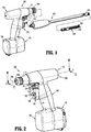
- Electromechanical surgical system 10 includes a surgical apparatus or device in the form of an electromechanical, hand-held, powered surgical instrument 100 that is configured for selective attachment thereto of a plurality of different end effectors 300, via an adapter assembly (e.g., elongated body) 200.
- the end effector 300 and the adapter assembly 200 are configured for actuation and manipulation by the electromechanical, hand-held, powered surgical instrument 100.
- the surgical instrument 100, the adapter assembly 200, and the end effector 300 are separable from each other such that the surgical instrument 100 is configured for selective connection with adapter assembly 200, and, in turn, adapter assembly 200 is configured for selective connection with any one of a plurality of different end effectors 300.
- the end effector and/or adapter can be configured as an integral unit in any of the embodiments disclosed herein.
- the end effector and/or adapter can be configured for use with a powered handle, console, and/or surgical robot, in any of the embodiments disclosed herein.
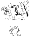
- the hand-held surgical instrument 100 includes a handle housing 102 having a lower housing portion 104, an intermediate housing portion 106 extending from and/or supported on lower housing portion 104, and an upper housing portion 108 extending from and/or supported on intermediate housing portion 106.
- Intermediate housing portion 106 and upper housing portion 108 are separated into a distal half-section 110a that is integrally formed with and extending from the lower portion 104, and a proximal half-section 110b connectable to distal half-section 110a by a plurality of fasteners.
- distal and proximal half-sections 110a, 110b define a handle housing 102 having a cavity 102a therein in which a circuit board 150 and a drive mechanism 160 are situated.
- distal and proximal half-sections 110a, 110b are divided along a vertical plane that traverses a longitudinal axis "A-A" of upper housing portion 108 ( Fig. 2 ).
- Handle housing 102 includes a gasket 112 extending completely around a rim of distal half-section and/or proximal half-section 110a, 110b and being interposed between distal half-section 110a and proximal half-section 110b.
- Gasket 112 seals the perimeter of distal half-section 110a and proximal half-section 110b.
- Gasket 112 functions to establish an air-tight seal between distal half-section 110a and proximal half-section 110b such that circuit board 150 and drive mechanism 160 are protected from sterilization and/or cleaning procedures.
- the cavity 102a of handle housing 102 is sealed along the perimeter of distal half-section 110a and proximal half-section 110b yet is configured to enable easier, more efficient assembly of circuit board 150 and a drive mechanism 160 in handle housing 102.
- Circuit board 150 is configured to control the various operations of surgical instrument 100, as will be set forth in additional detail below.
- Lower housing portion 104 of surgical instrument 100 defines an aperture (not shown) formed in an upper surface thereof and which is located beneath or within intermediate housing portion 106. As shown in Figs. 3 and 4 , the aperture of lower housing portion 104 provides a passage through which wires 152 pass to electrically interconnect electrical components situated in lower housing portion 104, e.g., a battery 156 and a circuit board 154, with electrical components situated in intermediate housing portion 106 and/or upper housing portion 108, e.g., circuit board 150, drive mechanism 160, etc.
- Handle housing 102 includes a gasket 107 disposed within the aperture of lower housing portion 104 thereby plugging or sealing the aperture of lower housing portion 104 while allowing wires 152 to pass therethrough (see FIG. 3 ).
- Gasket 107 functions to establish an air-tight seal between lower housing portion 106 and intermediate housing portion 108 such that circuit board 150 and drive mechanism 160 are protected from sterilization and/or cleaning procedures.
- lower housing portion 104 of handle housing 102 provides a housing in which the battery 156 is removably disposed therein.
- the battery 156 may be a rechargeable battery (e.g., lead-based, nickel-based, lithium-ion based, etc.). It is also envisioned that the battery 156 may be a single-use, non-rechargeable battery. Battery 156 is configured to supply power to any of the electrical components of surgical instrument 100.
- Lower housing portion 104 defines a cavity (not shown) into which battery 156 is inserted.
- Lower housing portion 104 includes a door 105 pivotally connected thereto for closing cavity of lower housing portion 104 and retaining battery 156 therein.
- distal half-section 110a of upper housing portion 108 defines a nose or connecting portion 108a.
- a nose cone 114 is supported on nose portion 108a of upper housing portion 108.
- Nose cone 114 is fabricated from a transparent, light-transmissive material.
- An illumination member 116 is disposed within nose cone 114 such that illumination member 116 is visible therethrough.
- the nose cone 114 may be tinted, such that the illumination member 116 is visible when it is activated.
- the illumination member 116 may include a plurality of any suitable light emitting devices, such as light emitting diodes (LEDs), disposed on printed circuit board (LED PCB) 116a which is disposed in a vertical plane transverse to the longitudinal axis "A-A."
- the illumination member 116 is configured to illuminate in multiple colors with a specific color pattern being associated with a unique discrete event.
- the LEDs may be single-color or multi-color LEDs.
- Upper housing portion 108 of handle housing 102 provides a housing in which drive mechanism 160 is situated.
- drive mechanism 160 is configured to drive shafts and/or gear components in order to perform the various operations of surgical instrument 100.
- drive mechanism 160 is configured to drive shafts and/or gear components in order to selectively move tool assembly 304 of end effector 300 relative to the adapter assembly, to rotate end effector 300 about the longitudinal axis "A-A" ( Fig. 2 ) relative to handle housing 102, to move anvil assembly 306 relative to cartridge assembly 308 of end effector 300, and/or to fire a stapling and cutting cartridge within cartridge assembly 308 of end effector 300.
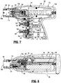
- the drive mechanism 160 includes a selector gearbox assembly 162 that is located immediately proximal relative to adapter assembly 200. Proximal to the selector gearbox assembly 162 is a function selection module 163 having a first (e.g., selector) motor 164 that functions to selectively move gear elements within the selector gearbox assembly 162 into engagement with an input drive component 165 having a second (e.g., drive) motor 166.
- a first (e.g., selector) motor 164 that functions to selectively move gear elements within the selector gearbox assembly 162 into engagement with an input drive component 165 having a second (e.g., drive) motor 166.
- distal half-section 110a of upper housing portion 108 defines a connecting portion 108a configured to accept a corresponding shaft coupling assembly 214 of adapter assembly 200.
- connecting portion 108a of surgical instrument 100 has a cylindrical recess 108b that receives the adapter assembly 200 when adapter assembly 200 is mated to surgical instrument 100.
- Connecting portion 108a houses three rotatable drive connectors 118, 120, 122.
- each of rotatable drive connectors 118, 120, 122 of surgical instrument 100 couples with a corresponding rotatable connector sleeve 218, 220, 222 of adapter assembly 200.
- the interface between corresponding first drive connector 118 and first connector sleeve 218, the interface between corresponding second drive connector 120 and second connector sleeve 220, and the interface between corresponding third drive connector 122 and third connector sleeve 222 are keyed such that rotation of each of drive connectors 118, 120, 122 of surgical instrument 100 causes a corresponding rotation of the corresponding connector sleeve 218, 220, 222 of adapter assembly 200.
- the hand-held surgical instrument 100 may include a first (e.g., selector) motor 164 that functions to selectively move the selector gearbox assembly 162 gears into engagement with an input drive component having a second (e.g., drive) motor.
- a first (e.g., selector) motor 164 that functions to selectively move the selector gearbox assembly 162 gears into engagement with an input drive component having a second (e.g., drive) motor.
- other motor arrangements may be used, such as a different motor may be used for driving each of the connector sleeves.
- other driving mechanisms for actuating the connector sleeves may be used, including, but not limited to, pneumatic and/or hydraulic drivers, solenoids, biasing members, and combinations thereof.
- drive connectors 118, 120, 122 of surgical instrument 100 with connector sleeves 218, 220, 222 of adapter assembly 200 allows rotational forces to be independently transmitted via each of the three respective connector interfaces.
- the drive connectors 118, 120, 122 of surgical instrument 100 are configured to be independently rotated by drive mechanism 160.
- the function selection module 163 of drive mechanism 160 selects which drive connector or connectors 118, 120, 122 of surgical instrument 100 is to be driven by the input drive component 165 of drive mechanism 160.
- the selector gearbox assembly 162 and the function selection module 163 are disclosed in more detail in a commonly-owned U.S. Patent Application Serial No. 13/280,898 , the entire contents of which is hereby incorporated by reference herein.
- each of drive connectors 118, 120, 122 of surgical instrument 100 has a keyed and/or substantially non-rotatable interface with respective connector sleeves 218, 220, 222 of adapter assembly 200, when adapter assembly 200 is coupled to surgical instrument 100, rotational force(s) are selectively transferred from drive mechanism 160 of surgical instrument 100 to adapter assembly 200.
- the selective rotation of drive connector(s) 118, 120 and/or 122 of surgical instrument 100 allows surgical instrument 100 to selectively actuate different functions of end effector 300.
- selective and independent rotation of first drive connector 118 of surgical instrument 100 corresponds to the selective and independent opening and closing of tool assembly 304 of end effector 300, and driving of a stapling/cutting component of tool assembly 304 of end effector 300.
- the selective and independent rotation of second drive connector 120 of surgical instrument 100 corresponds to the selective and independent articulation of tool assembly 304 of end effector 300 about an articulation axis "B-B" defined by a pin 505 ( Fig. 12 ) that is transverse to longitudinal axis "A-A" ( Fig. 2 ).
- the end effector 300 defines a second longitudinal axis "C-C” and is movable from a first position in which the second longitudinal axis "C-C” ( Fig. 12 ) is substantially aligned with the first longitudinal axis "A-A” to at least a second position in which the second longitudinal axis "C-C” is disposed at a non-zero angle with respect to the first longitudinal axis "A-A.”
- the selective and independent rotation of third drive connector 122 of surgical instrument 100 corresponds to the selective and independent rotation of end effector 300 about longitudinal axis "A-A" relative to handle housing 102 of surgical instrument 100.
- drive mechanism 160 includes a selector gearbox assembly 162; a function selection module 163, located proximal to the selector gearbox assembly 162, that functions to selectively move gear elements within the selector gearbox assembly 162 into engagement with second motor 166.
- drive mechanism 160 selectively drives one of drive connectors 118, 120, 122 of surgical instrument 100 at a given time.
- handle housing 102 supports a control assembly 103 on a distal surface or side of intermediate housing portion 108.
- Control assembly 103 in cooperation with intermediate housing portion 108, supports a pair of finger-actuated control buttons 124, 126 and rocker devices 128, 130.
- control assembly 103 defines an upper aperture 124a for slidably receiving a first control button 124, and a lower aperture 126b for slidably receiving a second control button 126.
- Each one of the control buttons 124, 126 and rocker devices 128, 130 includes a respective magnet (not shown) that is moved by the actuation of an operator.
- circuit board 150 includes, for each one of the control buttons 124, 126 and rocker devices 128, 130, respective Hall-effect switches 150a-150d that are actuated by the movement of the magnets in the control buttons 124, 126 and rocker devices 128, 130.
- a first Hall-effect switch 150a located immediately proximal to the control button 124 is a first Hall-effect switch 150a ( Figs. 3 and 7 ) that is actuated upon the movement of a magnet within the control button 124 upon the operator actuating control button 124.
- first Hall-effect switch 150a causes circuit board 150 to provide appropriate signals to function selection module 163 and input drive component 165 of the drive mechanism 160 to close a tool assembly 304 of end effector 300 and/or to fire a stapling/cutting cartridge within tool assembly 304 of end effector 300.
- second Hall-effect switch 150b located immediately proximal to rocker device 128 is a second Hall-effect switch 150b ( Figs. 3 and 7 ) that is actuated upon the movement of a magnet (not shown) within rocker device 128 upon the operator actuating rocker device 128.
- the actuation of second Hall-effect switch 150b, corresponding to rocker device 128, causes circuit board 150 to provide appropriate signals to function selection module 163 and input drive component 165 of drive mechanism 160 to articulate tool assembly 304 relative to the adapter assembly 200.
- movement of rocker device 128 in a first direction causes tool assembly 304 to articulate relative to the adapter assembly 200 in a first direction
- movement of rocker device 128 in an opposite, e.g., second, direction causes tool assembly 304 to articulate relative to the adapter assembly 200 in an opposite, e.g., second, direction.
- third Hall-effect switch 150c located immediately proximal to control button 126 is a third Hall-effect switch 150c ( Figs. 3 and 7 ) that is actuated upon the movement of a magnet (not shown) within control button 126 upon the operator actuating control button 126.
- the actuation of third Hall-effect switch 150c, corresponding to control button 126, causes circuit board 150 to provide appropriate signals to function selection module 163 and input drive component 165 of drive mechanism 160 to open tool assembly 304 of end effector 300.
- fourth Hall-effect switch 150d located immediately proximal to rocker device 130 is a fourth Hall-effect switch 150d ( Figs. 3 and 7 ) that is actuated upon the movement of a magnet (not shown) within rocker device 130 upon the operator actuating rocker device 130.
- the actuation of fourth Hall-effect switch 150d, corresponding to rocker device 130, causes circuit board 150 to provide appropriate signals to function selection module 163 and input drive component 165 of drive mechanism 160 to rotate end effector 300 relative to handle housing 102 surgical instrument 100.
- rocker device 130 in a first direction causes end effector 300 to rotate relative to handle housing 102 in a first direction
- movement of rocker device 130 in an opposite, e.g., second, direction causes end effector 300 to rotate relative to handle housing 102 in an opposite, e.g., second, direction.
- Adapter assembly 200 is configured to communicate the rotational forces of first, second and third rotatable drive connectors 118, 120, and 122 of surgical instrument 100 to end effector 300. As mentioned above, adapter assembly 200 is configured for selective connection to surgical instrument 100.
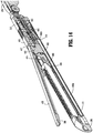
- adapter assembly 200 includes an elongate, substantially rigid, elongate body portion 210 having a proximal end 210a and a distal end 210b; a transmission housing 212 connected to proximal end 210a of elongate body portion 210 and being configured for selective connection to surgical instrument 100.
- the adapter assembly 200 also includes an articulating assembly 230 disposed at the distal end 210b for coupling to the end effector 300.
- the transmission housing 212 may include one or more gear train systems therein for varying a speed/force of rotation (e.g., increase or decrease) of first, second and/or third rotatable drive connectors 118, 120, and/or 122 of surgical instrument 100 before transmission of such rotational speed/force to end effector 300.
- a speed/force of rotation e.g., increase or decrease
- Transmission housing 212 of adapter assembly 200 is configured and adapted to connect to connecting portion 108a of upper housing portion 108 of surgical instrument 100. As seen in Figs. 1 and 6 , transmission housing 212 of adapter assembly 200 includes a shaft coupling assembly 214 supported at the proximal end 210a
- Adapter assembly 200 may include a first gear train system and a second gear train system, each disposed within transmission housing 212 and elongate body portion 210.
- Each gear train system is configured and adapted to vary a speed/force of rotation (e.g., increase or decrease) of first and second rotatable drive connectors 118 and 120 of surgical instrument 100 before transmission of such rotational speed/force to end effector 300.
- An adapter assembly having multiple gear trains is disclosed in more detail in a commonly-owned U.S. Patent No. 8,899,462 , the entire contents of which is hereby incorporated by reference herein.
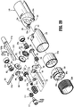
- adapter assembly 200 may rotatably support first, second, and third drive shafts 218a, 220a, 222a, which include a proximal end connected to transmission housing 212, namely, corresponding rotatable connector sleeve 218, 220, 222.
- Each of the drive shafts 218a, 220a, 222a also include a distal end extending to and operatively connected to the articulating assembly 230, as will be discussed in greater detail below.
- the elongate body portion 210 of adapter assembly 200 includes at least three longitudinally extending channels through body portion 210.
- the channels are configured and dimensioned to rotatably receive and support the drive shafts 218a, 220a, 222a, which may be connected to respective gear systems (not shown).
- Each of the drive shafts 218a, 220a, 222a are elongate and sufficiently rigid to transmit rotational forces from transmission housing 212 to articulating assembly 230, which are used to drive the end effector 300 as described in further detail below.
- End effector 300 includes a pair of jaw members, which include a cartridge assembly 308 and an anvil 306.
- Cartridge assembly 308 houses one or more fasteners 433 ( Fig. 13 ) that are disposed therewithin and is configured to deploy the fasteners 433 upon firing of instrument 100.
- the anvil 306 is movably (e.g., pivotally) mounted to the end effector 300 and is movable between an open position, spaced apart from cartridge assembly 308, and a closed position wherein anvil 306 is in close cooperative alignment with cartridge assembly 308, to thereby clamp tissue.
- the end effector 300 also includes a carrier 431 having an elongate channel 411, a base 412 and two parallel upstanding walls 414 and 416 which include several mounting structures, such as notches 439, for supporting the cartridge assembly 308 and the anvil 306.
- a longitudinal slot 413 extends through the elongate channel 411.
- the carrier 431 also includes a plate cover 415 disposed on a bottom surface thereof.
- the plate cover 415 is configured to frictionally engage with channel 411 of the carrier 431 and functions to protect tissue from moving parts along the exterior of carrier 431.
- the carrier 431 also includes a pair of tabs 407 and 409 disposed at a proximal end of respective walls 414, 416, and being configured for coupling to a housing portion 410 of end effector 300.
- the carrier 431 also includes a holder plate 402 disposed on a top surface thereof.
- the holder plate 402 is configured to frictionally engage the carrier 431 and the cartridge assembly 308 to secure the fasteners 433 and pushers 437 therein.
- the holder plate 402 includes a pair of distal wings 402a and a pair of proximal wings 402b configured to engage distal tabs 436a and proximal tabs 436b of the cartridge assembly 308, respectively.
- the distal wings 402a of the holder plate 402 are also configured and dimensioned to engage slots 439a disposed at a distal end of the carrier 431 thereby securing the cartridge assembly 308 to the carrier 431.
- the distal portion of channel 411 supports the cartridge assembly 308 which contains the plurality of surgical fasteners 433 and a plurality of corresponding ejectors or pushers 437.
- End effector 300 includes an actuation sled 440 having upstanding cam wedges 444 configured to exert a fastener driving force on the pushers 437, which drive the fasteners 433 from cartridge assembly 308, as described in more detail below.
- Cartridge assembly 308 is maintained within channel 411 by lateral struts 436 which frictionally engage corresponding notches 439 formed in the upper surfaces of channel walls 414 and 416. These structures serve to restrict lateral, longitudinal, and elevational movement of the cartridge assembly 308 within channel 411.
- the cartridge assembly 308 can be removable and replaceable so that the end effector 300 can be reused within a particular surgery allowing for multiple firings of a single end effector 300.
- a plurality of spaced apart longitudinal slots extend through cartridge assembly 308 and accommodate the upstanding cam wedges 444 of actuation sled 440.
- the slots communicate with a plurality of pockets 442 within which the plurality of fasteners 433 and pushers 437 are respectively supported.
- the pushers 437 are secured by a pusher retainer (not shown) disposed below the cartridge assembly 308, which supports and aligns the pushers 437 prior to engagement thereof by the actuation sled 440.
- the cartridge assembly 308 also includes a longitudinal slot 485 to allow for a knife blade 474 to travel therethrough, as described in more detail below.
- the end effector 300 includes an anvil cover 435 disposed over the anvil 306.
- the anvil cover 435 protects tissue from moving parts along the exterior of anvil 306.
- the anvil cover 435 includes opposed mounting wings 450 and 452 which are dimensioned and configured to engage detents 454 and 456 of the anvil 306, respectively.
- the mounting wings 450 and 452 function to align the anvil 306 with the cartridge assembly 308 during closure.
- the anvil 306 and the cover 435 are configured to remain in an open configuration until closed, as described in more detail below.
- the anvil 306 is pivotally coupled to the carrier 431.
- the carrier 431 includes a pair of openings 421 and 422 formed in respective tabs 407, 409.
- the anvil cover 435 also includes a pair of opposed openings 457 and 459 found therein.
- a pivot pin 417, or a pair of pins, passes through the openings 421, 422, 457, and 459 allowing for pivotal coupling of the anvil 306 to the carrier 431 and the cartridge assembly 308.
- end effector 300 further includes an axial drive screw 460 for transmitting the rotational drive forces exerted by the second drive shaft 220a, as described in further detail below, to actuation sled 440 during a stapling procedure.
- Drive screw 460 is rotatably supported in carrier 431 and includes a threaded portion 460a and a proximal engagement portion 460b.
- the drive screw 460 is rotatably secured by a thrust plate 410b within the distal housing member 410 such that the drive screw 460 may be rotated relative to the carrier 431.
- Distal housing member 410 of the end effector 300 is coupled to the proximal end of the carrier 431 via pivot pin 417.
- the housing member 410 includes a bore 414 ( Fig. 14 ) defined therethrough that houses the engagement portion 460b therein.
- the distal tip of the drive screw 460 rests in a recess defined in the channel 411 of the carrier 431.
- the drive screw 460 is coupled to a drive linkage 600, which mechanically engages the second drive shaft 220a, as described in further detail below, and the drive screw 460 of end effector 300.
- the drive linkage 600 disposed within the housing portion 410, is off-axis with respect to the drive screw 460.
- the longitudinal axis defined by the drive linkage 600 is at a non-parallel (e.g., non-zero angle) angle with respect to a longitudinal axis defined by the drive screw 460.
- the drive linkage 600 may be disposed along the same longitudinal axis as the drive screw 460.
- the drive linkage 600 includes a proximal engagement portion 601 and a distal engagement portion 603.
- the proximal engagement portion 601 is configured to be engaged by a coupling member 515
- the distal engagement portion 603 is dimensioned and configured to engage the proximal engagement portion 460b of drive screw 460.
- the engagement portion 601 includes a faceted surface, which is configured and dimensioned to interface with a socket 516 of the coupling member 515, which has a corresponding faceted surface.
- the engagement portion 603 also includes a faceted surface, which is configured and dimensioned to interface with a socket 460c of the engagement portion 460b, which has a corresponding faceted surface.
- the mechanical coupling of the engagement portions 601 and 603 with the sockets 516 and 460c, respectively, occurs via abutment of the male faceted surfaces of the engagement portions 601 and 603 with corresponding female faceted socket 516 and 460c, which allows for transfer of rotational motion of the coupling member 515 to the drive linkage 600 and, in turn, to the drive screw 460.
- the drive linkage 600 may mechanically interface with the drive screw 460 and the coupling member 515 using any other suitable mechanical coupling, e.g., pinned.
- end effector 300 further includes a drive beam 462 disposed within carrier 431.
- the drive beam 462 includes a vertical support strut 472 and an abutment surface 476, which engages the knife blade 474, which in turn, engages the actuation sled 440.
- the drive beam 462 also includes a cam member 480 disposed on top of the vertical support strut 472.
- Cam member 480 is dimensioned and configured to engage and translate with respect to an exterior camming surface 482 of anvil 306 to progressively clamp the anvil 306 against body tissue during firing.
- a longitudinal slot 484 extends through the anvil 306 to accommodate the translation of the vertical strut 472. This allows the cam member 480 to travel in between the cover 435 and anvil 306 during firing.
- the anvil cover 435 may also include a corresponding longitudinal slot (not shown) formed on an underside thereof and is secured to an upper surface of anvil 306 to form a channel therebetween.
- the drive beam 462 includes a retention portion 488 having a threaded bore 489 defined therethrough.
- the drive screw 460 is threadably coupled to the retention portion 480 through the bore 489, such that as the drive screw 460 is rotated, the drive beam 462 travels in a longitudinal direction along the longitudinal axis defined by the drive screw 460.
- the drive beam 462 In use, as the drive screw 460 is rotated in a clock-wise direction, the drive beam 462 travels in a distal direction closing the anvil 306 as the cam member 480 pushes down on the camming surface 482 thereof. The drive beam 462 also pushes the sled 440 in the distal direction, which then engages the pushers 437 via the cam wedges 444 to eject the fasteners 433.
- the drive beam 462 may be made of any suitable first material including, but not limited to, plastics, metals, and combinations thereof. The first and second materials may be either same or different.
- the knife blade 474 travels slightly behind actuation sled 440 during a stapling procedure to form an incision between the rows of fastener body tissue.
- the abutment surface 476 of the vertical strut 472 pushes the knife blade 474, which then pushes sled 440 in the distal direction to eject the fasteners 433 and simultaneously dissect tissue with the knife blade 474.
- the knife blade 474 and the drive beam 462 travel through the longitudinal slots 484 and 485.
- the drive beam 462 closes the anvil as it is driven in the distal direction and also pushes the sled 440, which, in turn, ejects the fasteners 433 ahead of the knife blade 474.
- the fasteners 433 are ejected they are deformed again the tissue-contacting (e.g., underside) surface of the anvil 306 having a plurality of anvil pockets (not shown).
- the assembly 230 includes a distal joint member 232 for coupling to a proximal end of the end effector 300 and a proximal joint member 234 coupled to the distal end 210b of the body portion 210.
- the housing portion 410 of the end effector 300 includes one or more posts 410a for insertion into one or more corresponding bores 580a within a socket 580.
- the socket 580 is rotationally disposed within the joint member 232.
- the socket 580 is disposed within a spacer 232a and includes a textured ring 232b disposed on an outer surface thereof. This allows the socket 580 to be rotated about the longitudinal axis "C-C" ( Fig. 12 ) by a shaft 513 that is longitudinally arranged within the joint member 232, as described in further detail below.
- the shaft 513 includes one or more facets 513a such that the shaft 513 is keyed to a central bore 580b of the socket 580. This allows for rotation of the socket 580 along with the shaft 513. As shown in Fig. 16 , during insertion the proximal engagement portion 601 of the drive linkage 600 also engages the socket 516 of the coupling member 515, which actuates the drive screw 460 as described in further detail below.
- the proximal joint member 234 and the distal joint member 232 are configured and dimensioned as a clevis to interface with a pin 505.
- the pin 505 includes one or more longitudinal facets 505a along at least a portion of the pin 505.
- the proximal joint member 234 of the neck assembly 230 includes a pair of opposing arms 235, 237 including a pair of opposing circular bores 235a, 237a, respectively, allowing the pin 505 to be rotationally coupled within the bores 235a, 237a of opposing arms 235, 237.
- the joint member 232 of the assembly 230 also includes a pair of opposing arms 239, 241 including a pair of opposing bores 239a, 241a.
- each of the bores 239a, 241a includes a facet 239b, 241b, such that when the pin 505 is inserted into the bores 235a, 237a, 239b, 241b, the pin 505 can rotate freely within the bores 235a, 237a. This secures the joint member 232 to the pin 505 about the bores 239a, 241a via mating of the facet 505a of the pin 505 with the facets 239b, and 241b.
- the joint member 232 along with the end effector 300 may be freely rotated with respect to the proximal joint member 234 about a articulation axis "B-B" ( Fig. 12 ) defined by the pin 505 as shown in Fig. 22 and described in further detail below.
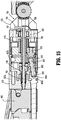
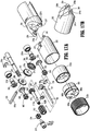
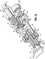
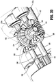
- the assembly 230 also includes the second (e.g., actuating/firing) drive shaft 220a, which may be axially rotatable within the body portion 210.
- the drive shaft 220a includes a second gear element 502 coupled thereto and configured to rotate therewith about a longitudinal axis defined by the drive shaft 220a.
- the gear element 502 is meshingly engaged with a first transfer gear element 504.
- the gear element 504 is held in position by the pin 505 and is configured to rotate about the pin 505.
- the gear element 504 is also meshingly engaged with a gear element 506 within the joint member 232.
- the gear elements 502, 504, 506 are bevel gears allowing for meshing engagement thereof even as the joint member 232 and the end effector 300 are pivoted with respect to the body portion 210.
- the gear element 502 rotates about a longitudinal axis parallel with the axis "A-A.”
- the gear element 504 rotates about the axis "B-B" ( Fig. 12 ) and the gear element 506 rotates about a longitudinal axis parallel with the axis "C-C" ( Figs. 2 and 10 ).
- the gear element 506 is connected to a gear element 510 by a shaft 508.
- the gear element 506, the gear element 510, and the shaft 508 rotate within the joint member 232 about a longitudinal axis defined by the central axis of the shaft 508.
- the gear element 510 is, in turn, meshingly engaged with a gear element 512 that rotates about the shaft 513 that is longitudinally arranged within the joint member 232.
- the gear element 512 is meshingly engaged with a gear element 514 of the coupling member 515.
- the coupling member 515 includes a shaft portion that extends distally to the socket 516, which is coupled to drive linkage 600 as described above.
- Rotation of the drive shaft 220a results in rotation of the gear elements 502, 504, 506, 510, 512, 514 and the socket 516, which in turn, rotates the drive screw 460 via the drive linkage 600 thereby actuating the firing process as described above.
- the assembly 230 also includes the third (e.g., rotating) drive shaft 222a, which may be axially rotatable within the body portion 210.
- the drive shaft 222a includes a third gear element 552 coupled thereto and configured to rotate therewith about a longitudinal axis defined by the drive shaft 222a.
- the gear element 552 is meshingly engaged with a second transfer gear element 554.
- the gear element 554 is held in position by the pin 505 and is configured to rotate about the pin 505.
- the gear element 554 is also meshingly engaged with a gear element 556 within the joint member 232.
- the gear elements 552, 554, 556 are bevel gears allowing for meshing engagement thereof even as the joint member 232 and the end effector 300 are pivoted with respect to the body portion 210.
- the gear element 552 rotates about a longitudinal axis parallel with the axis "A-A.”
- the gear element 554 rotates about the axis "B-B” and the gear element 556 rotates about a longitudinal axis parallel with the axis "C-C.”
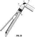
- Use of the bevel gears, namely, the gear elements 502, 504, 506, 552, 554, 556, allows for tightest possible 90° bend angle of the joint member 232 during articulation with respect to the body portion 210 of the adapter assembly 200 as shown in Fig. 23 , which shows the joint member 232 pivoted with respect to the joint member 234.
- the gear element 556 is connected to a gear element 560 by a shaft 558.
- the gear element 556, the gear element 560, and the shaft 558 rotate within the joint member 232 about a longitudinal axis defined by the central axis of the shaft 558.
- the gear element 560 is, in turn, meshingly engaged with a gear element 562, which is fixedly coupled to the shaft 513, such that rotation of the gear element 562 results in rotation of the shaft 513.
- the socket 580 is securedly coupled to the shaft 513, such that as the shaft 513 is rotated in either clockwise or counterclockwise direction about the longitudinal axis "C-C" the socket 580 is also rotated in the same direction. Since the end effector 300 is engaged with the socket 580 as described above, the end effector 300 is similarly rotated by the shaft 513.
- the end effector 300 is configured to rotate about its own longitudinal axis in this manner.
- the present disclosure also provides for a rotation lockout assembly 700 for preventing rotation of the end effector 300 during firing. This allows for prevention of tissue damage due to the torque generated during the firing process which would otherwise backfeed the gears within the neck assembly 230 and inadvertently rotate the end effector.
- the housing 410 may include a distal portion 427a and a proximal portion 427b interconnected by a bolt 429 with the bore 423a ( Fig. 13 ) defined therethrough.
- the shaft 513 disposed within the joint member 232 includes a bore 423b ( Fig. 17A ) defined therethrough.
- the bores 423a and 423b are in longitudinal alignment.
- the lockout assembly 700 includes a push rod 702 disposed within the bore 423a and a locking member 704 disposed within the joint member 232.
- the locking member 704 includes a rod 706 disposed within the bore 423b. The distal end of the rod 706 is in contact with a proximal end of the push rod 702, such that longitudinal movement of either the push rod 702 or the locking member 704 is translated therebetween.
- the locking member 704 also includes one or more lock lugs 707 configured and dimensioned to meshingly engage the gear element 562.
- the locking mechanism 700 also includes a spring 708, which is coupled to the joint member 232 and pushes the locking member 704 in a distal direction.
- the locking member 704 prior to insertion of the end effector 300 into the joint member 232, the locking member 704 is engaged with the lock lug 707 thereof preventing actuation of the coupling member 515.
- the drive beam 462 is in its proximal most position since it has not been fired and therefore abuts the distal end of the push rod 702. This moves the push rod 702 proximally, which also moves the locking member 704 in a proximal direction to disengage the lock lug 707 from the teeth of the gear element 562.
- the disengagement of the locking member 704 allows for rotation of the shaft 513, the socket 580, and in turn, the end effector 300 in either clockwise or counterclockwise direction about the longitudinal axis "C-C.”
- firing may be commenced as described above. Firing moves the drive beam 462 distally, which allows the push rod 702 along with the locking member 704 to travel distally due to the biasing forces of the spring 708 as shown in Fig. 24 . This moves the lock lug 707 of the locking member 704 into engagement with the gear element 562 preventing rotation of the end effector 300 during the firing process.
- the assembly also includes the first (e.g., pivoting) drive shaft 218a, which may be axially rotatable within the body portion 210.
- the drive shaft 218a includes a first gear element 570 at its distal end, which is configured as a worm gear.
- the gear element 570 is meshingly engaged with a pivoting gear element 572, which is configured as a worm wheel drive.
- the gear element 572 includes a bore 574a therethrough having a facet 574b.
- the gear element 572 is disposed between the gear elements 504, 554 and is secured to the pin 505 about the bore 574a via mating of the facet 505a of the pin 505 with the facet 574b of bore 574a of gear element 572 in a keyed relationship.
- the gear element 572 is secured to the pin 505 along with the joint member 232, which allows for rotation of the joint member 232 along with the end effector 300 with respect to the body portion 210 about the articulation axis "B-B" defined by the pin 505 as described in further detail below.
- articulation of the joint member 232 about the articulation axis "B-B" is imparted by rotation of the drive shaft 218a about its longitudinal axis and simultaneous longitudinal movement of the drive shaft 218a along its longitudinal axis, which in turn, rotates the gear element 572 via the gear element 570.
- Simultaneous rotational and longitudinal movement of the drive shaft 218a may be accomplished via a complementary worm gear mechanism at its proximal end. Since the gear element 572 is securedly coupled to the pin 505, rotation of the gear element 572 rotates the pin 505 and the joint member 232, which is also securedly coupled thereto as described above.
- the drive shaft 218a includes a thrust plate 218b that acts as a stop member preventing longitudinal movement of the drive shaft 218a beyond a certain point, which in turn, prevents rotation of the joint member 232 and the end effector 300 beyond a desired stopping point.
- the joint member 232 may be rotated about the articulation axis "B-B" up to about 300°, with about 150° in either direction from the first aligned position in which the second longitudinal axis "C-C" is substantially aligned with the first longitudinal axis "A-A.”
- the joint member 232 may be rotated about the articulation axis "B-B" up to about 180°, with about 90° in either direction from the first aligned position.
- the gearing relationship between the gear elements 570 and 572 allows for precise pivoting of the end effector 300 with respect to the adapter assembly 200.
- the gear elements 570 and 572 provide for a gearing reduction due to a worm gear/worm wheel drive relationship, thereby obviating the need for additional gear reduction mechanisms at the proximal end of the adapter assembly 200.
- FIG. 28-30 another embodiment of an articulating assembly 1230 provided in accordance with the present disclosure including a longitudinally translating drive shaft 1218a.
- Articulating assembly 1230 is substantially similar to articulating assembly 230 and includes most of the components of articulating assembly 230, which are not described below to avoid repetition.
- Drive shaft 1218a is operatively disposed within body portion 210.
- Drive shaft 1218a includes a first gear element 1570 that engages pivoting gear element 572.
- gear element 1570 may be configured as a toothed rack that engages pivoting gear element 572 in a rack and pinion relationship, as best illustrated in Fig. 30 .
- articulation of joint member 232 about articulation axis "B-B" is imparted by longitudinal translation of drive shaft 1218a along its longitudinal axis, which is parallel to the longitudinal axis "A-A" ( Fig. 10 ).
- Longitudinal movement of drive shaft 1218a rotates pivoting gear element 572 via first gear element 1570.
- the longitudinal translation of drive shaft 1218a may be accomplished via a drive mechanism described above with respect to drive shaft 218a.
- First gear element 1570 may extend along drive shaft 1218a such that a portion of first gear element 1570 is adjacent a proximal end of drive shaft 1218a. Since pivoting gear element 572 is securely coupled to pin 505, rotation of pivoting gear element 572 rotates pin 505 and joint member 232, which is also securely coupled thereto as described above.
- Drive shaft 1218a also includes a thrust plate 1218b that acts as a stop member preventing longitudinal translation of drive shaft 1218a beyond certain limits (e.g., a proximal limit 1219a or a distal limit 1219b), which in turn, prevents rotation of joint member 232 and end effector 300 beyond a desired point.
- joint member 232 may be pivoted about the articulation axis "B-B" to a first and second pivoted positions in either direction from a first aligned position in which the second longitudinal axis "C-C" ( Fig. 28 ) is substantially aligned with the first longitudinal axis "A-A" ( Fig. 10 ).
- the first and second pivoted positions may be up to about 300°, with about 150° of pivot in either direction from the first aligned position.
- joint member 232 may be pivoted about the articulation axis "B-B" up to about 180°, with about 90° of pivot in either direction from the first aligned position.
- gear elements 1570 and 572 allow for precise pivoting of end effector 300 with respect to adapter assembly 200.
- the interaction of gear elements 1570 and 572 may provide for a back drive mechanism that permits external forces exerted on an end effector attached to articulating neck assembly 1230 about the pivot axis to back drive the motor until a solid stop is reached (i.e., thrust plate 1218b reaching proximal or distal limit 1219a, 1219b).
- the solid stop may correspond to the first or second rotated positions of end effector 300.
- the back drive mechanism may also include a force multiplier configured to reduce the force exerted on the motor by the back drive mechanism.
- the force multiplier may be from about 1 to about 40, in embodiments, from about 5 to about 20.
- the hand-held instrument handle housed a removable and replaceable and/or rechargeable battery, as well as a motor and computer and memory components.
- a removable and replaceable adapter assembly corresponds to one or more end effector configurations, the end effectors being removable and replaceable.
- an adapter is configured for use with circular stapling reload end effectors in various sizes, and with or without various other features such as suction and irrigation, visualization, etc.
- Other adapters are available for use with linear surgical stapling reloads come in various sizes, configurations, possibly having other features such as dissection tips and/or pre-loaded surgical buttress material.
- the handle may be disposable, for single-procedure use, or sterilizable and re-used for a prescribed number of procedures.
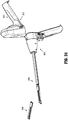
- a surgical stapling handle 2010 contains a removable and re-usable motor and battery (not shown), and the handle housing 2012 itself opens and closes to receive those components. This may extend the useful life of the motor, which can be housed in the handle housing in a sealed fashion, avoiding the need to sterilize the motor, the battery, etc.
- the handle housing 2012 is openable like a shell, as shown and is re-sterilizable.
- the handle housing carries a series of buttons 2014 and controls for actuating articulation, clamping of tissue, stapling of tissue and cutting of the tissue. These buttons, as well as various indicators (such as lights, screens and the like) can be as discussed above or similar thereto.
- the controller desirably contains a microprocessor and memory components that record information concerning the use of the instrument and can interact with sensor provided in the other components such as the end effector reload, adapter, staple cartridge assembly, etc.
- the adapter assembly 2016 can be removable, as mentioned above, or it can be permanently attached to the handle.
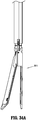
- the adapter assembly includes a drive mechanism which has mechanical components for manipulating the end effector ( Fig. 34A ), such as articulation, opening and closing of jaws, etc.
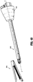
- the adapter assembly 2016 has a proximal end 2018 with a knob 2020, and a distal end 2022 that can be attached to a surgical stapling end effector reload 3010.
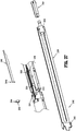
- the proximal end 2018 has a lead screw 2026 with a proximal end 2028 that is accessible at the proximal end 2018 of the adapter assembly 2016.
- An inner tube 2030 is threadably engaged with (i.e., it has helical grooves) the lead screw, which also has helical threads so that rotation of the lead screw 2026 will translate the inner tube 2030 in a proximal or distal direction.
- a thrust bearing 2032 ( Fig. 36 ) at the proximal end of the lead screw so that it is mounted in the knob 2020.
- a pusher 2034 is attached to the distal end 2026a of the lead screw and is connected to a bar 2036 through a pin, screw, or the like.
- the inner tube 2030, thrust bearing 2032, and pusher 2034 can also be seen in Figs. 39A and 39B
- the adapter assembly has a drive mechanism inside an elongate shaft that articulates.
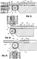
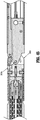
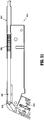
- the distal end 2022 of the adapter assembly 2016 has a pair of bar guides 2038, one each on either side of a bar 2036, and adjacent to the bar guides is a pair of blowout plates 2046 that are next to the bar guides, but distal to them.
- the bar itself is made of a plurality of layers, or stainless steel or equivalent material, that are stacked against one another.
- a beam is attached to the bar.
- the beam shown is an I-beam 2042 having an upper flange 2042a and a lower flange 2042b is attached.
- the bar is further supported by a support block 2044 that has an opening 2046 so that it surrounds the bar, and the blowout plates 2046.
- the support block is curved in shape, with the convex side of the support block facing proximally, and is made of a strong material like stainless steel.
- the blowout plates each have a distal end 2046a that form a flange 2048 for being received in a slot in a mounting member 2050.
- the mounting member 2050 forms the distal end of the adapter assembly 2016 and can be attached to the end effector reload.
- the mounting member 2050 also has an arcuate slot for receiving and supporting the support block 2044, and also allowing the support block 2044 to move so that the assembly (the bar, blowout plates, support block) move off-center with respect to the adapter assembly when the end effector reload is articulated and pivoted with respect to the adapter (see Fig. 38 ).
- the bar guides 2038 are moved as well (see Fig. 39 ).
- the bar, the pair of bar guides, the pair of blowout plates, and the support block are pivotable from a central position in the adapter assembly to an off-center position in the adapter assembly.
- the distal ends of the bar guides pivot off-center, supporting the blowout plates and the plurality of layers forming the bar.
- the guides pivot off-center, it creates a large radius for the bar to be driven through, reducing stress on the bar, and the layers making up the bar.
- the bar guides are separate members, but they pivot together. The assembly works in the same way when articulated in the opposite direction.
- the end effector reload 3010 has an anvil assembly 3012, a cartridge assembly 3014, and a channel 3016 for receiving the cartridge assembly.
- the entire end effector reload 3010 can be attached to the adapter assembly 2016, and removed and replaced after use.
- the anvil assembly 3012 can be one or more parts machined and/or welded together, and having an anvil plate 3012a with recesses shaped for forming the staples into a closed shape when they are driven against the anvil plate 3012a.
- the staple cartridge assembly 3014 is attached to the channel 3016 and has an upper surface with slots (also seen in Fig. 50 ) that house the unformed staples and allow their ejection from the cartridge assembly 3014 and into tissue.
- the anvil assembly 3012, staple cartridge assembly 3014, and channel 3016 have slots that allow the passage of the I-beam 2042 and bar 2036.
- the layers of the bar 2036 are dimensioned so that they extend into both the slot in the anvil assembly 3012 and the slot in the channel 3016.
- the staple cartridge assembly 3014 has a sled 3018 that carries a knife 3020 rotatably supported on the sled.
- the knife can be biased in an upward position for cutting tissue, or it can be biased in a downward position where it does not access tissue, and/or the knife 3020 can be moved by a feature on the I-beam 2042. As shown in Fig.
- the feature of the I-beam can be a slot 3022 for camming a protrusion 3024 on the knife 3020.
- the engagement of the flanges 2042a and 2042b of the I-beam with the anvil assembly and channel move the anvil assembly, staple cartridge assembly, and channel into approximation to engage tissue.
- the I-beam 2042 pushes the sled 3018 and knife 3020 distally.
- the sled interacts with pushers in the staple cartridge assembly to drive the staples out of the slots.
- the knife can be formed directly on the I-beam 2042.
- the proximal end 3030a of the articulation mechanism 3030 of the adapter assembly 2016 is shown in Fig. 41 .
- a cylindrical articulation nut 3032 having threads on its proximal end 3034.
- An input shaft 3036 with corresponding threads is enmeshed with the threads of the nut 3032.
- the rotating shaft 3036 will rotate the nut 3032 through the operation of the threads.
- the interior of the nut 3032 is hollow and also has a helical groove 3038.
- the groove 3038 is engaged with a groove 3040 on the outside of a screw 3042 ( Fig. 42 ) disposed inside the nut 3032.
- the screw moves distally or proximally, to move an articulation link 3044. In this way, distal movement of the link will articulate or pivot the end effector in one direction, and proximal movement of the link 3044 will articulate or pivot the end effector in the other direction.
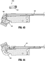
- the distal end 3030b of the articulation mechanism 3030 of the adapter assembly 2016 is shown in Fig. 43 .
- the articulation link 3044 ends in a connection to a second link which is a short link 3048, via a pin.
- the short link is curved and also pinned to the mounting member 2050 at an off-center location.
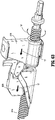
- the mounting member 2050 is connected to the adapter assembly 2016 at a pin 3050a and the mounting member 2050 pivots about the pin 3050 when the links 3044, 3048 are moved. (See Fig. 44 and 45 ).
- the adapter assembly 2016 proximal end 2018 knob 2020 houses a mechanism for rotating the entire adapter assembly about its own longitudinal axis "A".
- a rotation input shaft 3052 rotates a gear 3054 that is enmeshed with a ring gear 3055. When the input shaft rotates, it rotates the knob 2020, outer tube 2021, and everything attached to it. ( Fig. 45A ).
- Fig. 46 shows the attachment of the end effector reload 3010 to the adapter assembly.
- the anvil assembly 3012 has a semi-cylindrical proximal end 3012a that forms tissue stops 3060.
- the tissue stops 3060 form walls, one on each side of the reload 3010.
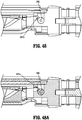
- the locking tabs each have an extension 3062a that is received in a connection feature of the mounting member.
- the connection feature of the mounting member is a pair of keyways 2051 defined in the mounting member 2050.
- the keyways each form a slot that receives the extension 3062a to lock the reload onto the adapter assembly.
- the keyways slots are upwardly open, so that the end effector reload is locked onto the adapter assembly through movement of the reload downwardly.
- Spring fingers 2051a engage the locking tab extensions.
- Fig. 48A Spring fingers 2051a engage the locking tab extensions.
- the example described above has a staple cartridge assembly that is not intended to be removed and replaced in the end effector reload 3010.
- the adapter assembly 2016 and end effector reload 3010 are as described above, except that the end effector reload has a removable and replaceable staple cartridge assembly.
- the staple cartridge assembly 3014" has a snap-fit arrangement at its proximal end, formed by a rearward-facing opening 3014a" in the staple cartridge body 4015 and a corresponding opening 3018a" in the support tray. These openings engage a boss 3016a"in the channel 3016" in a snap-fit relationship.
- the end effector reload, adapter assembly, and stapler handle can be reused to fire another set of staples, without replacing the end effector reload.
- the length of the staple lines depends on the selection of the end effector reload, that component must be replaced to change the length of the staple lines formed in tissue.
- the size of the staples, and the arrangement of staples (more than one staple size, or all the same size staples), whether there is a pre-loaded buttress or curved tip or other feature can be changed by changing the selection of the staple cartridge assembly 3014".
- a manually actuated stapler handle, in an instrument having a removable and replaceable staple cartridge assembly is disclosed in U.S. Patent. No. 9,016,539 , the entire disclosure of which is hereby incorporated by reference herein.
- Fig. 51 shows an articulation mechanism having a threaded engagement in the distal portion of the adapter assembly 4016.
- the articulation mechanism is as described above, and has an articulation link 4044, and a short link 4048, connected to one another by a pin 4046.
- the drive shaft 4049 extends to the distal end of the adapter assembly 4016 and forms a series of threads 4050 on its distal end.
- the threads 4050 are engaged with threads on the articulation link and are used to translate the articulation link 4044 when the drive shaft 4049 rotates.
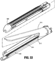
- End effector 5000 includes a tool assembly 5100 (e.g., a multi-use loading unit or MULU) and a cartridge assembly 5200 that mounts to tool assembly 5100. Similar to tool assembly 304 above, tool assembly 5100 generally includes a first jaw member 5110 and a second jaw member 5112 that are pivotally coupled together. Second jaw member 5112 supports cartridge assembly 5200, which may be selectively replaceable, a lead screw 5114, and an I-beam 5116 (see Fig.
- a tool assembly 5100 e.g., a multi-use loading unit or MULU
- cartridge assembly 5200 that mounts to tool assembly 5100. Similar to tool assembly 304 above, tool assembly 5100 generally includes a first jaw member 5110 and a second jaw member 5112 that are pivotally coupled together. Second jaw member 5112 supports cartridge assembly 5200, which may be selectively replaceable, a lead screw 5114, and an I-beam 5116 (see Fig.
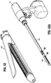
- End effector 5000 is configured to couple to an adapter assembly 200x that selectively couples to surgical instrument 100 (see Fig. 52A ).
- cartridge assembly 5200 of end effector 5000 includes a cartridge holder 5210 and a cartridge 5220 having a tissue-contacting surface 5222.
- Cartridge holder 5210 and cartridge 5220 of cartridge assembly 5200 support pushers 5230, fasteners 5240 supported on pushers 5230, and a sled assembly 5250 that is slidably advanceable along cartridge assembly 5200 to fire fasteners 5240 from cartridge 5220 as pushers 5230 cam along sled assembly 5250.
- sled assembly 5250 includes an actuation sled 5252 and a knife assembly 5254 pivotally supported on actuation sled 5252 between a first position and a second position.
- Actuation sled 5252 includes a plurality of upstanding cam wedges 5252a separated by a knife mount 5252b and configured to exert a fastener driving force on pushers 5230 ( Fig. 54 ).
- Knife mount 5252b defines a spring bore 5252c and a vertical channel 5252d therein.
- Knife mount 5252b further includes a pivot pin 5252e that extends transversely from a sidewall 5252f of knife mount 5252b to pivotally support knife assembly 5254 thereon, a stabilizing finger 5252g that extends proximally from knife mount 5252b and is positioned to provide lateral stability to knife assembly 5254 when the knife assembly 5254 is disposed in the second position, and a blocking arm 5252h that extends over knife assembly 5254 and is positioned to support knife assembly 5254 in the second position to facilitate tissue cutting.
- Knife assembly 5254 includes a spring 5254a (e.g., compression spring) that is received within spring bore 5252c of knife mount 5252b, and a knife 5254b engaged with spring 5254a.
- spring 5254a e.g., compression spring
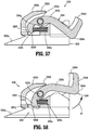
- knife 5254b of knife assembly 5254 is pivotally supported on pivot pin 5252e to enable knife 5254b to pivot (e.g., rotate) about pivot pin 5252e between a first position ( Fig. 55 ), in which knife 5254b is disposed below tissue-contacting surface 5222 of cartridge 5220 to prevent tissue cutting, and a second position ( Fig. 56 ), in which knife 5254b is raised above tissue-contacting surface 5222 of cartridge 5220 to enable tissue cutting for tissue supported on tissue-contacting surface 5222.
- Knife 5254b of knife assembly 5254 includes a knife arm 5254c that supports a blade 5254d on a knife head 5254x disposed a proximal end portion of knife 5254b. Knife 5254b further defines a pivot hole 5254e on a distal end portion thereof that receives the pivot pin 5252e of knife mount 5252b. Knife arm 5254c includes an arched configuration and is positioned to engage a bottom surface of blocking arm 5252h of knife mount 5252b to prevent knife 5254b from pivoting beyond the second position of knife 5254b.
- Knife arm 5254c further includes a distal foot 5254f that engages spring 5254a to enable spring 5254a to urge knife 5254b toward the first position in which blade 5254d of knife 5254b is positioned below blocking arm 5252h of knife mount 5252b (see Fig. 57 ).
- Distal foot 5254f includes an arch 5254g along which a distal portion of spring 5254a cams as knife 5254b pivots about pivot pin 5252e.
- Spring 5254a of knife assembly 5254 is positioned to urge distal foot 5254f distally to maintain knife 5254b in the first position (e.g., so that blade 5254d remains below tissue-contacting surface 5222 of cartridge 5220).
- Distal foot 5254f further includes a proximal toe 5254h that is receivable in vertical channel 5252d of knife mount 5252b as knife 5254b pivots relative to knife mount 5252b from the first position to the second position.
- I-beam 5116 is advanced between first and second jaw members 5110, 5112 to approximate or clamp first and second jaw members 5110, 5112 together (see Fig. 60 ).
- a distal surface 5116a of I-beam 5116 is spaced from a proximal surface 5252x of actuation sled 5252 of sled assembly 5250, and knife head 5254x of knife 5254b of sled assembly 5250 is in contact with a camming surface 5116b of I-beam 5116.
- knife head 5254x of knife 5254b of sled assembly 5250 cams upwardly along camming surface 5116b of I-beam 5116 and against spring biasing forces imparted by spring 5254a of knife assembly 5254.
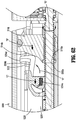
- knife 5254b pivots (e.g., rotates) upwardly and distally, as indicated by arrow "A,” from the first position toward the second position (see Fig. 62 ).
- distal surface 5116a of I-beam 5116 approximates proximal surface 5252x of actuation sled 5252.
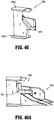
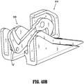
- knife head 5254x of knife assembly 5254 may include a guide pin that extends transversely therefrom and that is configured to translate through a slot defined in, for example, an I-beam (see e.g., slot 3022 in Fig. 40 ) to facilitate pivoting movement of knife 5254b (see e.g., Figs. 40A and 40B which illustrate a similar embodiment with such a guide pin "GP").
- a guide pin that extends transversely therefrom and that is configured to translate through a slot defined in, for example, an I-beam (see e.g., slot 3022 in Fig. 40 ) to facilitate pivoting movement of knife 5254b (see e.g., Figs. 40A and 40B which illustrate a similar embodiment with such a guide pin "GP").
- surgical instrument 100 and/or end effector 300 need not apply staples but rather may apply two part fasteners as is known in the art. Further, the length of the linear row of staples or fasteners may be modified to meet the requirements of a particular surgical procedure.
- the length of the linear row of staples and/or fasteners within a staple cartridge assembly may be varied accordingly.
- the elements and features shown or described in connection with certain embodiments may be combined with the elements and features of certain other embodiments without departing from the scope of the present disclosure, and that such modifications and variations are also included within the scope of the present disclosure. Accordingly, the subject matter of the present disclosure is not limited by what has been particularly shown and described.
Landscapes
- Health & Medical Sciences (AREA)
- Life Sciences & Earth Sciences (AREA)
- Surgery (AREA)
- Heart & Thoracic Surgery (AREA)
- Engineering & Computer Science (AREA)
- Biomedical Technology (AREA)
- Nuclear Medicine, Radiotherapy & Molecular Imaging (AREA)
- Medical Informatics (AREA)
- Molecular Biology (AREA)
- Animal Behavior & Ethology (AREA)
- General Health & Medical Sciences (AREA)
- Public Health (AREA)
- Veterinary Medicine (AREA)
- Surgical Instruments (AREA)
Abstract
Description
- The present application is a Continuation-in-Part of
U.S. Patent Application Serial No. 16/158,427, filed October 12, 2018 U.S. Provisional Patent Application Serial No. 62/578,673, filed October 30, 2017 - The present disclosure relates to surgical apparatus, devices and/or systems for performing endoscopic surgical procedures and methods of use thereof. More specifically, the present disclosure relates to manual, electromechanical, robotic and/or hand-held surgical apparatus, devices and/or systems configured for use with removable disposable loading units and/or single use loading units for clamping, cutting and/or stapling tissue.
- A number of surgical device manufacturers have developed product lines with proprietary drive systems for operating and/or manipulating electromechanical surgical devices. In many instances the electromechanical surgical devices include a handle assembly, which is reusable, and disposable loading units and/or single use loading units or the like that are selectively connected to the handle assembly prior to use and then disconnected from the handle assembly following use in order to be disposed of or in some instances sterilized for re-use.
- Various electromechanical linkages are utilized to transmit power from the reusable handle assemblies, which include one or more motors, to the disposable loading unit to effect rotation, pivoting, clamping, fastener ejection, etc. Due to the complex structure and operation of the power transmission mechanisms inadvertent actuation of these mechanisms may result in unintended operation of the disposable loading unit, which may result in damage to the surgical device and/or injury to the patient. Robotic systems for performing minimally invasive surgery are also known. For example, International Application Publication
WO 2000/051486 discloses a system having remotely-controlled surgical instruments. - Many of these electromechanical surgical devices are relatively expensive to manufacture, purchase and/or operate. There is a constant desire by manufacturers and end users to develop electromechanical surgical devices that are relatively inexpensive to manufacture, purchase and/or operate that still provide a large degree of operability with prerequisite safety features. Accordingly, a need exists for electromechanical surgical apparatus, devices and/or systems that include effective electromechanical transmission system for actuating the disposable units as well as safety lockout assemblies.
- In a first aspect of the present disclosure, a surgical stapling instrument comprises a reload including a staple cartridge assembly and an anvil assembly moveable with respect to one another. An adapter assembly has an elongate shaft and an articulating distal end, a mounting member being disposed at the distal end and being pivotally attached to the elongate shaft, the mounting member having a connection feature for attaching the reload to the adapter assembly. A drive mechanism is in the adapter, the drive mechanism including a bar extending through the mounting member and having a beam at a distal end of the bar, the bar being flexible and supported by a pair of bar guides, one of the bar guides alongside a first side of the bar, and the other of the bar guides being alongside a second side of the bar, the bar being further supported by a pair of blowout plates, one of the blowout plates being alongside the first side of the bar, and the other of the blowout plates being alongside the second side of the bar, the pair of blowout plates being distal to the pair of bar guides, the bar being further supported by a support block having an opening, the bar and the pair of blowout plates being disposed in the opening of the support block, the bar, the pair of bar guides, the pair of blowout plates, and the support block being pivotable from a central position in the adapter assembly to an off-center position in the adapter assembly.
- The support block can be curved. The mounting member can have a curved slot. The support block can be disposed in the curved slot so that the support block is movable in the curved slot.
- An articulation link extends inside the elongate shaft, and a second link pivotally connected to the articulation link and to the mounting member. The second link can be curved.
- The bar can have a plurality of layers stacked together. The beam can have an upper flange and a lower flange. The bar can be attached to a threaded drive member. The threaded drive member may be disposed inside an inner tube having an interior thread. The connection feature can define a keyway. The reload may define a tab that is received in the keyway.
- In another aspect, a surgical stapling system comprises: a hand-held instrument handle having a battery, a motor and computer and memory components; a removable and replaceable adapter assembly; a first linear surgical stapling reload having a first end effector, the first linear surgical stapling reload being removably and replaceably attachable to the adapter assembly; and a second linear surgical stapling reload having a second end effector and being removably and replaceably attachable to the adapter assembly, the second linear surgical stapling reload having a feature and the first linear stapling reload not having the feature, each of the first linear surgical stapling reload and the second linear surgical stapling reload having a staple cartridge assembly and an anvil assembly.
- The adapter assembly corresponds to the first linear surgical stapling reload and the second linear surgical stapling reload. The feature can be a dissecting tip on a distal end of the anvil assembly of the second linear surgical stapling reload.
- The feature can be a stapling buttress on each of the anvil assembly and the staple cartridge assembly of the second linear surgical stapling reload.
- The handle can be sterilizable and re-used for a prescribed number of procedures.
- In accordance with yet another aspect of the present disclosure, a surgical stapling system including a cartridge assembly is provided. The cartridge assembly includes a cartridge and a sled assembly configured to drive fasteners through the cartridge. The cartridge has a tissue-contacting surface. The sled assembly includes a knife pivotally coupled to the sled assembly. The knife has a blade and is positioned to pivot distally from a first position where the blade is disposed below the tissue-contacting surface to a second position where the blade is disposed above the tissue-contacting surface.
- In some embodiments, the sled assembly may include knife mount that has a blocking surface. The blocking surface may extend over the knife and may be positioned to support the knife in the second position. The knife may include a knife arm that is coupled to the knife mount by a pivot pin to enable the knife to pivot relative to the knife mount. The knife may be coupled to a spring that is engaged with the knife mount and positioned to urge a distal foot of the knife arm distally so that the blade, which is supported on a proximal portion of the knife arm, is urged toward the first position. The knife mount may include a stabilizing finger that extends from the knife mount to support the knife when the knife is in the second position.
- Further details and aspects of exemplary embodiments of the present disclosure are described in more detail below with reference to the appended figures.
- Embodiments of the present disclosure are described herein with reference to the accompanying drawings, wherein:
-
Fig. 1 is a perspective, disassembled view of an electromechanical surgical system including a surgical instrument, an adapter assembly, and an end effector, according to the present disclosure; -
Fig. 2 is a perspective view of the surgical instrument ofFig. 1 , according to the present disclosure; -
Fig. 3 is perspective, disassembled view of the surgical instrument ofFig. 1 , according to the present disclosure; -
Fig. 4 is a perspective view of a battery of the surgical instrument ofFig. 1 , according to the present disclosure; -
Fig. 5 is a top, partially-disassembled view of the surgical instrument ofFig. 1 , according to the present disclosure; -
Fig. 6 is a front, perspective view of the surgical instrument ofFig. 1 with the elongated member separated therefrom, according to the present disclosure; -
Fig. 7 is a cross-sectional side view of the surgical instrument ofFig. 1 , as taken through 7-7 ofFig. 1 , according to the present disclosure; -
Fig. 8 is a top, cross-sectional view of the surgical instrument ofFig. 1 , as taken through 8-8 ofFig. 1 , according to the present disclosure; -
Fig. 9 is a perspective, disassembled view of a control assembly of the surgical instrument ofFig. 1 , according to the present disclosure; -
Fig. 10 is a perspective view of the adapter assembly ofFig. 1 having an articulating neck assembly, according to the present disclosure; -
Fig. 11 is a perspective, partial cross-sectional view of the adapter assembly ofFig. 1 , according to the present disclosure; -
Fig. 12 is a perspective view of an end effector connected to a distal end of the adapter assembly ofFig. 1 , oriented in a linear, non-articulated orientation, according to the present disclosure; -
Fig. 13 is a disassembled view of the end effector ofFig. 12 , according to the present disclosure; -
Fig. 14 is a perspective, cross-sectional view of the end effector ofFig. 12 , according to the present disclosure; -
Fig. 15 is an enlarged, cross-sectional side view of the end effector ofFig. 12 , according to the present disclosure; -
Fig. 16 is an enlarged, cross-sectional side view of the end effector ofFig. 12 disconnected from the articulating neck assembly, according to the present disclosure; -
Fig. 17A is a disassembled view of the articulating neck assembly according to the present disclosure; -
FIG. 17B is a perspective view of part of the articulating neck assembly according to the present disclosure; -
Fig. 18 is a top perspective, partially-disassembled view of the articulating neck assembly according to the present disclosure; -
Fig. 19 is a bottom perspective, partially-disassembled view of the articulating neck assembly according to the present disclosure; -
Fig. 20 is a side perspective, partially-disassembled view of the articulating neck assembly according to the present disclosure; -
Fig. 21 is a top perspective, partially-disassembled view of the articulating neck assembly according to the present disclosure; -
Fig. 22 is a top perspective view of the articulating neck assembly according to the present disclosure; -
Fig. 23 is a side view of the articulating neck assembly in an articulated orientation, according to the present disclosure; -
Fig. 24 is an enlarged, cross-sectional side view of the end effector ofFig. 12 connected to the articulating neck assembly, according to the present disclosure; -
Fig. 25 is a cross-sectional side view of the end effector ofFig. 12 connected to the articulating neck assembly oriented in a linear, non-articulated orientation, according to the present disclosure; -
Fig. 26 is a cross-sectional side view of the end effector ofFig. 12 connected to the articulating neck assembly oriented in a first articulated orientation, according to the present disclosure; -
Fig. 27 is a cross-sectional side view of the end effector ofFig. 12 connected to the articulating neck assembly oriented in a second articulated orientation, according to the present disclosure; -
Fig. 28 is a perspective view of another embodiment of an articulating neck assembly with an end effector connected to a distal end of the adapter assembly ofFig. 1 , oriented in a linear, non-articulated orientation, according to the present disclosure; -
Fig. 29 is a perspective, disassembled view of the articulating neck assembly ofFig. 28 according to the present disclosure; -
Fig. 30 is a top perspective, partially-disassembled view of the articulating neck assembly ofFig. 28 according to the present disclosure; -
Fig. 31 is a cross-sectional, side view of the end effector connected to the articulating neck assembly ofFig. 28 oriented in a linear, non-articulated orientation, according to the present disclosure; -
Fig. 32 is a cross-sectional, side view of the end effector connected to the articulating neck assembly ofFig. 28 oriented in a first articulated orientation, according to the present disclosure; -
Fig. 33 is a cross-sectional, side view of the end effector connected to the articulating neck assembly ofFig. 28 oriented in a second articulated orientation, according to the present disclosure; -
Fig. 34 is a perspective view of a surgical stapling instrument according to another aspect of the present disclosure: -
Fig. 34A is an elevation view of the end effector reload and the distal end of the adapter assembly; -
Fig. 35 is a perspective view of an adapter assembly and an end effector reload for the surgical stapling instrument; -
Fig. 36 is a cross-sectional view of the adapter assembly for the surgical stapling instrument ofFigs. 34-35 ; -
Fig. 37 is a perspective view of the articulating portion of the adapter assembly; -
Fig. 38 is a cross-sectional view of the articulating portion of the adapter assembly; -
Fig. 39 is a perspective view of the articulating portion of the adapter assembly; -
Fig. 39A is a cross-sectional view of the proximal end of the adapter assembly; -
Fig. 39B is a perspective view of the lead screw of the adapter assembly; -
Fig. 40 is a perspective view of an I-beam for the surgical stapling instrument; -
Fig. 40A is a perspective view of the I-beam and sled for the surgical stapling instrument; -
Fig. 40B is a perspective view of the I-beam and sled for the surgical stapling instrument; -
Fig. 41 is a perspective view of the articulation mechanism in the proximal end of the adapter assembly; -
Fig. 42 is a cross-sectional view of the articulation mechanism in the proximal end of the adapter assembly; -
Fig. 43 is a plan view of the articulation mechanism in the distal end of the adapter assembly; -
Fig. 44 is a plan view of the articulation mechanism in the distal end of the adapter assembly; -
Fig. 45 is a perspective view of the articulation mechanism in the distal end of the adapter assembly; -
Fig. 45A is a perspective view of a gear assembly in the adapter assembly; -
Fig. 46 is a perspective view of the end effector reload and distal end of the adapter assembly; -
Fig. 47 is a perspective view of the proximal end of the end effector reload; -
Fig. 48 is a plan view of the end effector reload and distal end of the adapter assembly; -
Fig. 48A is a cross-sectional view of the end effector reload and distal end of the adapter assembly; -
Fig. 49 is a perspective view of the adapter assembly and end effector reload showing the reload unattached to the adapter assembly; -
Fig. 50 is an exploded view of the staple cartridge assembly and anvil assembly; -
Fig. 51 is a plan view of a different example of an articulation mechanism in the distal end of an adapter assembly; -
Fig. 52 is a perspective view of another embodiment of an end effector of the electromechanical surgical system ofFig. 1 , the end effector illustrated in an unclamped position; -
Fig. 52A is a perspective view illustrating the end effector ofFig. 52 secured to the electromechanical surgical system ofFig. 1 ; -
Fig. 53 is a perspective view of the end effector ofFig. 52 with a cartridge assembly of the end effector shown separated from a tool assembly of the end effector; -
Fig. 54 is a perspective view, with parts separated, of the cartridge assembly ofFig. 53 ; -
Fig. 55 is an enlarged perspective view of a sled assembly of the cartridge assembly ofFig. 54 , the sled assembly including a blade shown in a first position; -
Fig. 56 is a perspective view of the sled assembly ofFig. 55 with the blade thereof shown in a second position; -
Fig. 57 is a side, cross-sectional view of the sled assembly ofFigs. 55 and56 as taken along section line 57-57 seen inFig. 55 ; -
Fig. 58 is a side, cross-sectional view of the sled assembly ofFigs. 55 and56 as taken along section line 58-58 seen inFig. 56 ; -
Fig. 59 is a perspective view, with parts separated, of the sled assembly ofFigs. 55 and56 ; -
Fig. 60 is a side, cross-sectional view of the end effector ofFig. 52 as taken along section line 60-60 shown inFig. 52A , the end effector shown in a clamped position; -
Figs. 61-62 are enlarged progressive views of the indicated area of detail shown inFig. 60 ; and -
Fig. 63 is a perspective view illustrating the blade of the sled assembly ofFIGS. 55 and56 in the second position and engaged with an I-beam of the end effector ofFig. 52 . - Embodiments of the presently disclosed electromechanical surgical system, apparatus and/or device are described in detail with reference to the drawings, in which like reference numerals designate identical or corresponding elements in each of the several views. As used herein the term "distal" refers to that portion of the electromechanical surgical system, apparatus and/or device, or component thereof, that are farther from the user, while the term "proximal" refers to that portion of the electromechanical surgical system, apparatus and/or device, or component thereof, that are closer to the user. The terms "left" and "right" refer to that portion of the electromechanical surgical system, apparatus and/or device, or component thereof, that are on the left and right sides, respectively, from the perspective of the user facing the distal end of the electromechanical surgical system, apparatus and/or device from the proximal end while the surgical system, apparatus and/or device is oriented in non-rotational configuration.
- Reference may be made to International Application Publication No.
WO 2009/039506 ,U.S. Patent No. 9,775,610 US 2011/0121049 , the entire contents of each of which are incorporated by reference herein, for a detailed description of the construction and operation of exemplary electromechanical, hand-held, poweredsurgical instrument 100. - Referring initially to
Figs. 1-8 , an electromechanical, hand-held, powered surgical system, in accordance with an embodiment of the present disclosure is shown and generally designated 10. Electromechanical surgical system 10 includes a surgical apparatus or device in the form of an electromechanical, hand-held, poweredsurgical instrument 100 that is configured for selective attachment thereto of a plurality ofdifferent end effectors 300, via an adapter assembly (e.g., elongated body) 200. Theend effector 300 and theadapter assembly 200 are configured for actuation and manipulation by the electromechanical, hand-held, poweredsurgical instrument 100. In particular, thesurgical instrument 100, theadapter assembly 200, and theend effector 300 are separable from each other such that thesurgical instrument 100 is configured for selective connection withadapter assembly 200, and, in turn,adapter assembly 200 is configured for selective connection with any one of a plurality ofdifferent end effectors 300. - The end effector and/or adapter can be configured as an integral unit in any of the embodiments disclosed herein. The end effector and/or adapter can be configured for use with a powered handle, console, and/or surgical robot, in any of the embodiments disclosed herein.
- As illustrated in
Figs. 1-3 , the hand-heldsurgical instrument 100 includes ahandle housing 102 having alower housing portion 104, anintermediate housing portion 106 extending from and/or supported onlower housing portion 104, and anupper housing portion 108 extending from and/or supported onintermediate housing portion 106.Intermediate housing portion 106 andupper housing portion 108 are separated into a distal half-section 110a that is integrally formed with and extending from thelower portion 104, and a proximal half-section 110b connectable to distal half-section 110a by a plurality of fasteners. When joined, distal and proximal half-sections handle housing 102 having acavity 102a therein in which acircuit board 150 and adrive mechanism 160 are situated. - With reference to
Figs. 2 and3 , distal and proximal half-sections Fig. 2 ). Handlehousing 102 includes agasket 112 extending completely around a rim of distal half-section and/or proximal half-section section 110a and proximal half-section 110b.Gasket 112 seals the perimeter of distal half-section 110a and proximal half-section 110b.Gasket 112 functions to establish an air-tight seal between distal half-section 110a and proximal half-section 110b such thatcircuit board 150 anddrive mechanism 160 are protected from sterilization and/or cleaning procedures. - In this manner, the
cavity 102a ofhandle housing 102 is sealed along the perimeter of distal half-section 110a and proximal half-section 110b yet is configured to enable easier, more efficient assembly ofcircuit board 150 and adrive mechanism 160 inhandle housing 102. -
Intermediate housing portion 106 ofhandle housing 102 provides a housing in whichcircuit board 150 is situated.Circuit board 150 is configured to control the various operations ofsurgical instrument 100, as will be set forth in additional detail below. -
Lower housing portion 104 ofsurgical instrument 100 defines an aperture (not shown) formed in an upper surface thereof and which is located beneath or withinintermediate housing portion 106. As shown inFigs. 3 and 4 , the aperture oflower housing portion 104 provides a passage through whichwires 152 pass to electrically interconnect electrical components situated inlower housing portion 104, e.g., abattery 156 and acircuit board 154, with electrical components situated inintermediate housing portion 106 and/orupper housing portion 108, e.g.,circuit board 150,drive mechanism 160, etc. - Handle
housing 102 includes agasket 107 disposed within the aperture oflower housing portion 104 thereby plugging or sealing the aperture oflower housing portion 104 while allowingwires 152 to pass therethrough (seeFIG. 3 ).Gasket 107 functions to establish an air-tight seal betweenlower housing portion 106 andintermediate housing portion 108 such thatcircuit board 150 anddrive mechanism 160 are protected from sterilization and/or cleaning procedures. - With continued reference to
Figs. 3 and 4 ,lower housing portion 104 ofhandle housing 102 provides a housing in which thebattery 156 is removably disposed therein. Thebattery 156 may be a rechargeable battery (e.g., lead-based, nickel-based, lithium-ion based, etc.). It is also envisioned that thebattery 156 may be a single-use, non-rechargeable battery.Battery 156 is configured to supply power to any of the electrical components ofsurgical instrument 100.Lower housing portion 104 defines a cavity (not shown) into whichbattery 156 is inserted.Lower housing portion 104 includes adoor 105 pivotally connected thereto for closing cavity oflower housing portion 104 and retainingbattery 156 therein. - With continued reference to
Figs. 3 and5 , distal half-section 110a ofupper housing portion 108 defines a nose or connectingportion 108a. Anose cone 114 is supported onnose portion 108a ofupper housing portion 108.Nose cone 114 is fabricated from a transparent, light-transmissive material. Anillumination member 116 is disposed withinnose cone 114 such thatillumination member 116 is visible therethrough. Thenose cone 114 may be tinted, such that theillumination member 116 is visible when it is activated. - With reference to
Fig. 5 , theillumination member 116 may include a plurality of any suitable light emitting devices, such as light emitting diodes (LEDs), disposed on printed circuit board (LED PCB) 116a which is disposed in a vertical plane transverse to the longitudinal axis "A-A." Theillumination member 116 is configured to illuminate in multiple colors with a specific color pattern being associated with a unique discrete event. In embodiments, the LEDs may be single-color or multi-color LEDs. -
Upper housing portion 108 ofhandle housing 102 provides a housing in which drivemechanism 160 is situated. As illustrated inFig. 5 ,drive mechanism 160 is configured to drive shafts and/or gear components in order to perform the various operations ofsurgical instrument 100. In particular,drive mechanism 160 is configured to drive shafts and/or gear components in order to selectively movetool assembly 304 ofend effector 300 relative to the adapter assembly, to rotateend effector 300 about the longitudinal axis "A-A" (Fig. 2 ) relative to handlehousing 102, to moveanvil assembly 306 relative tocartridge assembly 308 ofend effector 300, and/or to fire a stapling and cutting cartridge withincartridge assembly 308 ofend effector 300. - The
drive mechanism 160 includes aselector gearbox assembly 162 that is located immediately proximal relative toadapter assembly 200. Proximal to theselector gearbox assembly 162 is afunction selection module 163 having a first (e.g., selector)motor 164 that functions to selectively move gear elements within theselector gearbox assembly 162 into engagement with aninput drive component 165 having a second (e.g., drive)motor 166. - As illustrated in
Figs. 1-4 , distal half-section 110a ofupper housing portion 108 defines a connectingportion 108a configured to accept a correspondingshaft coupling assembly 214 ofadapter assembly 200. - As illustrated in
Figs. 6-8 , connectingportion 108a ofsurgical instrument 100 has acylindrical recess 108b that receives theadapter assembly 200 whenadapter assembly 200 is mated tosurgical instrument 100. Connectingportion 108a houses three rotatable driveconnectors - With reference to
Fig. 6 , whenadapter assembly 200 is mated tosurgical instrument 100, each ofrotatable drive connectors surgical instrument 100 couples with a correspondingrotatable connector sleeve adapter assembly 200. In this regard, the interface between correspondingfirst drive connector 118 andfirst connector sleeve 218, the interface between correspondingsecond drive connector 120 andsecond connector sleeve 220, and the interface between correspondingthird drive connector 122 andthird connector sleeve 222 are keyed such that rotation of each ofdrive connectors surgical instrument 100 causes a corresponding rotation of the correspondingconnector sleeve adapter assembly 200. - In the above-described embodiments, the hand-held
surgical instrument 100 may include a first (e.g., selector)motor 164 that functions to selectively move theselector gearbox assembly 162 gears into engagement with an input drive component having a second (e.g., drive) motor. In embodiments, other motor arrangements may be used, such as a different motor may be used for driving each of the connector sleeves. In further embodiments, other driving mechanisms for actuating the connector sleeves may be used, including, but not limited to, pneumatic and/or hydraulic drivers, solenoids, biasing members, and combinations thereof. - The mating of
drive connectors surgical instrument 100 withconnector sleeves adapter assembly 200 allows rotational forces to be independently transmitted via each of the three respective connector interfaces. Thedrive connectors surgical instrument 100 are configured to be independently rotated bydrive mechanism 160. In this regard, thefunction selection module 163 ofdrive mechanism 160 selects which drive connector orconnectors surgical instrument 100 is to be driven by theinput drive component 165 ofdrive mechanism 160. Theselector gearbox assembly 162 and thefunction selection module 163 are disclosed in more detail in a commonly-ownedU.S. Patent Application Serial No. 13/280,898 , the entire contents of which is hereby incorporated by reference herein. - Since each of
drive connectors surgical instrument 100 has a keyed and/or substantially non-rotatable interface withrespective connector sleeves adapter assembly 200, whenadapter assembly 200 is coupled tosurgical instrument 100, rotational force(s) are selectively transferred fromdrive mechanism 160 ofsurgical instrument 100 toadapter assembly 200. - The selective rotation of drive connector(s) 118, 120 and/or 122 of
surgical instrument 100 allowssurgical instrument 100 to selectively actuate different functions ofend effector 300. As discussed in greater detail below, selective and independent rotation offirst drive connector 118 ofsurgical instrument 100 corresponds to the selective and independent opening and closing oftool assembly 304 ofend effector 300, and driving of a stapling/cutting component oftool assembly 304 ofend effector 300. Also, the selective and independent rotation ofsecond drive connector 120 ofsurgical instrument 100 corresponds to the selective and independent articulation oftool assembly 304 ofend effector 300 about an articulation axis "B-B" defined by a pin 505 (Fig. 12 ) that is transverse to longitudinal axis "A-A" (Fig. 2 ). In particular, theend effector 300 defines a second longitudinal axis "C-C" and is movable from a first position in which the second longitudinal axis "C-C" (Fig. 12 ) is substantially aligned with the first longitudinal axis "A-A" to at least a second position in which the second longitudinal axis "C-C" is disposed at a non-zero angle with respect to the first longitudinal axis "A-A." Additionally, the selective and independent rotation ofthird drive connector 122 ofsurgical instrument 100 corresponds to the selective and independent rotation ofend effector 300 about longitudinal axis "A-A" relative to handlehousing 102 ofsurgical instrument 100. - As illustrated in
Figs. 5 and8 ,drive mechanism 160 includes aselector gearbox assembly 162; afunction selection module 163, located proximal to theselector gearbox assembly 162, that functions to selectively move gear elements within theselector gearbox assembly 162 into engagement withsecond motor 166. Thus,drive mechanism 160 selectively drives one ofdrive connectors surgical instrument 100 at a given time. - As illustrated in
Figs. 1-3 andFig. 9 , handlehousing 102 supports acontrol assembly 103 on a distal surface or side ofintermediate housing portion 108.Control assembly 103, in cooperation withintermediate housing portion 108, supports a pair of finger-actuatedcontrol buttons rocker devices control assembly 103 defines an upper aperture 124a for slidably receiving afirst control button 124, and a lower aperture 126b for slidably receiving asecond control button 126. - Each one of the
control buttons rocker devices circuit board 150 includes, for each one of thecontrol buttons rocker devices effect switches 150a-150d that are actuated by the movement of the magnets in thecontrol buttons rocker devices control button 124 is a first Hall-effect switch 150a (Figs. 3 and7 ) that is actuated upon the movement of a magnet within thecontrol button 124 upon the operatoractuating control button 124. The actuation of first Hall-effect switch 150a, corresponding to controlbutton 124, causescircuit board 150 to provide appropriate signals to functionselection module 163 andinput drive component 165 of thedrive mechanism 160 to close atool assembly 304 ofend effector 300 and/or to fire a stapling/cutting cartridge withintool assembly 304 ofend effector 300. - Also, located immediately proximal to
rocker device 128 is a second Hall-effect switch 150b (Figs. 3 and7 ) that is actuated upon the movement of a magnet (not shown) withinrocker device 128 upon the operatoractuating rocker device 128. The actuation of second Hall-effect switch 150b, corresponding torocker device 128, causescircuit board 150 to provide appropriate signals to functionselection module 163 andinput drive component 165 ofdrive mechanism 160 to articulatetool assembly 304 relative to theadapter assembly 200. Advantageously, movement ofrocker device 128 in a first direction causestool assembly 304 to articulate relative to theadapter assembly 200 in a first direction, while movement ofrocker device 128 in an opposite, e.g., second, direction causestool assembly 304 to articulate relative to theadapter assembly 200 in an opposite, e.g., second, direction. - Furthermore, located immediately proximal to
control button 126 is a third Hall-effect switch 150c (Figs. 3 and7 ) that is actuated upon the movement of a magnet (not shown) withincontrol button 126 upon the operatoractuating control button 126. The actuation of third Hall-effect switch 150c, corresponding to controlbutton 126, causescircuit board 150 to provide appropriate signals to functionselection module 163 andinput drive component 165 ofdrive mechanism 160 to opentool assembly 304 ofend effector 300. - In addition, located immediately proximal to
rocker device 130 is a fourth Hall-effect switch 150d (Figs. 3 and7 ) that is actuated upon the movement of a magnet (not shown) withinrocker device 130 upon the operatoractuating rocker device 130. The actuation of fourth Hall-effect switch 150d, corresponding torocker device 130, causescircuit board 150 to provide appropriate signals to functionselection module 163 andinput drive component 165 ofdrive mechanism 160 to rotateend effector 300 relative to handlehousing 102surgical instrument 100. Specifically, movement ofrocker device 130 in a first direction causesend effector 300 to rotate relative to handlehousing 102 in a first direction, while movement ofrocker device 130 in an opposite, e.g., second, direction causesend effector 300 to rotate relative to handlehousing 102 in an opposite, e.g., second, direction. - Turning now to
Figs. 1 and10 ,adapter assembly 200 will be shown in detail and described.Adapter assembly 200 is configured to communicate the rotational forces of first, second and thirdrotatable drive connectors surgical instrument 100 to endeffector 300. As mentioned above,adapter assembly 200 is configured for selective connection tosurgical instrument 100. - As seen in
Figs. 1 ,6 ,10 , and11 adapter assembly 200 includes an elongate, substantially rigid,elongate body portion 210 having aproximal end 210a and adistal end 210b; atransmission housing 212 connected toproximal end 210a ofelongate body portion 210 and being configured for selective connection tosurgical instrument 100. Theadapter assembly 200 also includes an articulatingassembly 230 disposed at thedistal end 210b for coupling to theend effector 300. - In embodiments, the
transmission housing 212 may include one or more gear train systems therein for varying a speed/force of rotation (e.g., increase or decrease) of first, second and/or thirdrotatable drive connectors surgical instrument 100 before transmission of such rotational speed/force to endeffector 300. -
Transmission housing 212 ofadapter assembly 200 is configured and adapted to connect to connectingportion 108a ofupper housing portion 108 ofsurgical instrument 100. As seen inFigs. 1 and6 ,transmission housing 212 ofadapter assembly 200 includes ashaft coupling assembly 214 supported at theproximal end 210a -
Adapter assembly 200 may include a first gear train system and a second gear train system, each disposed withintransmission housing 212 andelongate body portion 210. Each gear train system is configured and adapted to vary a speed/force of rotation (e.g., increase or decrease) of first and secondrotatable drive connectors surgical instrument 100 before transmission of such rotational speed/force to endeffector 300. An adapter assembly having multiple gear trains is disclosed in more detail in a commonly-ownedU.S. Patent No. 8,899,462 , the entire contents of which is hereby incorporated by reference herein. - As seen in
Fig. 11 ,adapter assembly 200 may rotatably support first, second, andthird drive shafts transmission housing 212, namely, correspondingrotatable connector sleeve drive shafts assembly 230, as will be discussed in greater detail below. Theelongate body portion 210 ofadapter assembly 200 includes at least three longitudinally extending channels throughbody portion 210. The channels are configured and dimensioned to rotatably receive and support thedrive shafts drive shafts transmission housing 212 to articulatingassembly 230, which are used to drive theend effector 300 as described in further detail below. -
Figs. 12-16 illustrate components and operation of theend effector 300.End effector 300 includes a pair of jaw members, which include acartridge assembly 308 and ananvil 306.Cartridge assembly 308 houses one or more fasteners 433 (Fig. 13 ) that are disposed therewithin and is configured to deploy thefasteners 433 upon firing ofinstrument 100. Theanvil 306 is movably (e.g., pivotally) mounted to theend effector 300 and is movable between an open position, spaced apart fromcartridge assembly 308, and a closed position whereinanvil 306 is in close cooperative alignment withcartridge assembly 308, to thereby clamp tissue. - Referring to
Fig. 13 , a disassembled view of theend effector 300 is shown. Theend effector 300 also includes acarrier 431 having anelongate channel 411, abase 412 and two parallelupstanding walls notches 439, for supporting thecartridge assembly 308 and theanvil 306. A longitudinal slot 413 extends through theelongate channel 411. - The
carrier 431 also includes aplate cover 415 disposed on a bottom surface thereof. Theplate cover 415 is configured to frictionally engage withchannel 411 of thecarrier 431 and functions to protect tissue from moving parts along the exterior ofcarrier 431. Thecarrier 431 also includes a pair oftabs respective walls housing portion 410 ofend effector 300. - The
carrier 431 also includes aholder plate 402 disposed on a top surface thereof. Theholder plate 402 is configured to frictionally engage thecarrier 431 and thecartridge assembly 308 to secure thefasteners 433 andpushers 437 therein. Theholder plate 402 includes a pair ofdistal wings 402a and a pair ofproximal wings 402b configured to engagedistal tabs 436a andproximal tabs 436b of thecartridge assembly 308, respectively. Thedistal wings 402a of theholder plate 402 are also configured and dimensioned to engageslots 439a disposed at a distal end of thecarrier 431 thereby securing thecartridge assembly 308 to thecarrier 431. - With continuing reference to
Fig. 13 , the distal portion ofchannel 411 supports thecartridge assembly 308 which contains the plurality ofsurgical fasteners 433 and a plurality of corresponding ejectors orpushers 437.End effector 300 includes anactuation sled 440 havingupstanding cam wedges 444 configured to exert a fastener driving force on thepushers 437, which drive thefasteners 433 fromcartridge assembly 308, as described in more detail below.Cartridge assembly 308 is maintained withinchannel 411 bylateral struts 436 which frictionally engage correspondingnotches 439 formed in the upper surfaces ofchannel walls cartridge assembly 308 withinchannel 411. In any of the embodiments disclosed herein, thecartridge assembly 308 can be removable and replaceable so that theend effector 300 can be reused within a particular surgery allowing for multiple firings of asingle end effector 300. - A plurality of spaced apart longitudinal slots (not shown) extend through
cartridge assembly 308 and accommodate theupstanding cam wedges 444 ofactuation sled 440. The slots communicate with a plurality ofpockets 442 within which the plurality offasteners 433 andpushers 437 are respectively supported. Thepushers 437 are secured by a pusher retainer (not shown) disposed below thecartridge assembly 308, which supports and aligns thepushers 437 prior to engagement thereof by theactuation sled 440. During operation, asactuation sled 440 translates throughcartridge assembly 308, the angled leading edges ofcam wedges 444 sequentiallycontact pushers 437 causing the pushers to translate vertically within slots 446, urging thefasteners 306 therefrom. Thecartridge assembly 308 also includes alongitudinal slot 485 to allow for aknife blade 474 to travel therethrough, as described in more detail below. - With continuing reference to
Figs. 13 and14 , theend effector 300 includes ananvil cover 435 disposed over theanvil 306. Theanvil cover 435 protects tissue from moving parts along the exterior ofanvil 306. Theanvil cover 435 includes opposed mountingwings detents anvil 306, respectively. The mountingwings anvil 306 with thecartridge assembly 308 during closure. Theanvil 306 and thecover 435 are configured to remain in an open configuration until closed, as described in more detail below. - The
anvil 306 is pivotally coupled to thecarrier 431. Thecarrier 431 includes a pair ofopenings respective tabs anvil cover 435 also includes a pair ofopposed openings pivot pin 417, or a pair of pins, passes through theopenings anvil 306 to thecarrier 431 and thecartridge assembly 308. - As seen in
Figs. 13 and14 ,end effector 300 further includes anaxial drive screw 460 for transmitting the rotational drive forces exerted by thesecond drive shaft 220a, as described in further detail below, toactuation sled 440 during a stapling procedure.Drive screw 460 is rotatably supported incarrier 431 and includes a threadedportion 460a and aproximal engagement portion 460b. Thedrive screw 460 is rotatably secured by athrust plate 410b within thedistal housing member 410 such that thedrive screw 460 may be rotated relative to thecarrier 431.Distal housing member 410 of theend effector 300 is coupled to the proximal end of thecarrier 431 viapivot pin 417. Thehousing member 410 includes a bore 414 (Fig. 14 ) defined therethrough that houses theengagement portion 460b therein. The distal tip of thedrive screw 460 rests in a recess defined in thechannel 411 of thecarrier 431. - As shown in
Figs. 13-15 , thedrive screw 460 is coupled to adrive linkage 600, which mechanically engages thesecond drive shaft 220a, as described in further detail below, and thedrive screw 460 ofend effector 300. Thedrive linkage 600, disposed within thehousing portion 410, is off-axis with respect to thedrive screw 460. In particular, the longitudinal axis defined by thedrive linkage 600 is at a non-parallel (e.g., non-zero angle) angle with respect to a longitudinal axis defined by thedrive screw 460. In embodiments, thedrive linkage 600 may be disposed along the same longitudinal axis as thedrive screw 460. - With reference to
Fig. 15 , thedrive linkage 600 includes aproximal engagement portion 601 and adistal engagement portion 603. Theproximal engagement portion 601 is configured to be engaged by acoupling member 515, and thedistal engagement portion 603 is dimensioned and configured to engage theproximal engagement portion 460b ofdrive screw 460. In particular, theengagement portion 601 includes a faceted surface, which is configured and dimensioned to interface with asocket 516 of thecoupling member 515, which has a corresponding faceted surface. Theengagement portion 603 also includes a faceted surface, which is configured and dimensioned to interface with a socket 460c of theengagement portion 460b, which has a corresponding faceted surface. The mechanical coupling of theengagement portions sockets 516 and 460c, respectively, occurs via abutment of the male faceted surfaces of theengagement portions faceted socket 516 and 460c, which allows for transfer of rotational motion of thecoupling member 515 to thedrive linkage 600 and, in turn, to thedrive screw 460. In embodiments, thedrive linkage 600 may mechanically interface with thedrive screw 460 and thecoupling member 515 using any other suitable mechanical coupling, e.g., pinned. - With reference to
Figs. 13 and14 ,end effector 300 further includes adrive beam 462 disposed withincarrier 431. Thedrive beam 462 includes avertical support strut 472 and anabutment surface 476, which engages theknife blade 474, which in turn, engages theactuation sled 440. Thedrive beam 462 also includes a cam member 480 disposed on top of thevertical support strut 472. Cam member 480 is dimensioned and configured to engage and translate with respect to anexterior camming surface 482 ofanvil 306 to progressively clamp theanvil 306 against body tissue during firing. - A
longitudinal slot 484 extends through theanvil 306 to accommodate the translation of thevertical strut 472. This allows the cam member 480 to travel in between thecover 435 andanvil 306 during firing. In embodiments, theanvil cover 435 may also include a corresponding longitudinal slot (not shown) formed on an underside thereof and is secured to an upper surface ofanvil 306 to form a channel therebetween. - The
drive beam 462 includes aretention portion 488 having a threadedbore 489 defined therethrough. Thedrive screw 460 is threadably coupled to the retention portion 480 through thebore 489, such that as thedrive screw 460 is rotated, thedrive beam 462 travels in a longitudinal direction along the longitudinal axis defined by thedrive screw 460. - In use, as the
drive screw 460 is rotated in a clock-wise direction, thedrive beam 462 travels in a distal direction closing theanvil 306 as the cam member 480 pushes down on thecamming surface 482 thereof. Thedrive beam 462 also pushes thesled 440 in the distal direction, which then engages thepushers 437 via thecam wedges 444 to eject thefasteners 433. Thedrive beam 462 may be made of any suitable first material including, but not limited to, plastics, metals, and combinations thereof. The first and second materials may be either same or different. - The
knife blade 474 travels slightly behindactuation sled 440 during a stapling procedure to form an incision between the rows of fastener body tissue. As thedrive beam 462 is driven in the distal direction, theabutment surface 476 of thevertical strut 472 pushes theknife blade 474, which then pushessled 440 in the distal direction to eject thefasteners 433 and simultaneously dissect tissue with theknife blade 474. Theknife blade 474 and thedrive beam 462 travel through thelongitudinal slots drive beam 462 closes the anvil as it is driven in the distal direction and also pushes thesled 440, which, in turn, ejects thefasteners 433 ahead of theknife blade 474. As thefasteners 433 are ejected they are deformed again the tissue-contacting (e.g., underside) surface of theanvil 306 having a plurality of anvil pockets (not shown). - With reference to
Figs. 11 ,12 , and14-17A , the articulatingassembly 230 is shown. Theassembly 230 includes a distaljoint member 232 for coupling to a proximal end of theend effector 300 and a proximaljoint member 234 coupled to thedistal end 210b of thebody portion 210. - With reference to
Figs. 13 and16-21 thehousing portion 410 of theend effector 300 includes one ormore posts 410a for insertion into one or morecorresponding bores 580a within asocket 580. Thesocket 580 is rotationally disposed within thejoint member 232. In particular, thesocket 580 is disposed within aspacer 232a and includes atextured ring 232b disposed on an outer surface thereof. This allows thesocket 580 to be rotated about the longitudinal axis "C-C" (Fig. 12 ) by ashaft 513 that is longitudinally arranged within thejoint member 232, as described in further detail below. - The
shaft 513 includes one ormore facets 513a such that theshaft 513 is keyed to acentral bore 580b of thesocket 580. This allows for rotation of thesocket 580 along with theshaft 513. As shown inFig. 16 , during insertion theproximal engagement portion 601 of thedrive linkage 600 also engages thesocket 516 of thecoupling member 515, which actuates thedrive screw 460 as described in further detail below. - With reference to
Figs. 17A-19 , the proximaljoint member 234 and the distaljoint member 232 are configured and dimensioned as a clevis to interface with apin 505. Thepin 505 includes one or morelongitudinal facets 505a along at least a portion of thepin 505. The proximaljoint member 234 of theneck assembly 230 includes a pair of opposingarms circular bores pin 505 to be rotationally coupled within thebores arms Figs. 17A-B , thejoint member 232 of theassembly 230 also includes a pair of opposingarms bores Fig. 17B , each of thebores facet pin 505 is inserted into thebores pin 505 can rotate freely within thebores joint member 232 to thepin 505 about thebores facet 505a of thepin 505 with thefacets pin 505 is keyed to thebores joint member 232 and is free-floating within thebores joint member 234, thejoint member 232 along with theend effector 300 may be freely rotated with respect to the proximaljoint member 234 about a articulation axis "B-B" (Fig. 12 ) defined by thepin 505 as shown inFig. 22 and described in further detail below. - With reference to
Figs. 17A and18 , theassembly 230 also includes the second (e.g., actuating/firing)drive shaft 220a, which may be axially rotatable within thebody portion 210. Thedrive shaft 220a includes asecond gear element 502 coupled thereto and configured to rotate therewith about a longitudinal axis defined by thedrive shaft 220a. Thegear element 502 is meshingly engaged with a firsttransfer gear element 504. Thegear element 504 is held in position by thepin 505 and is configured to rotate about thepin 505. - The
gear element 504 is also meshingly engaged with agear element 506 within thejoint member 232. Thegear elements joint member 232 and theend effector 300 are pivoted with respect to thebody portion 210. Thegear element 502 rotates about a longitudinal axis parallel with the axis "A-A." Thegear element 504 rotates about the axis "B-B" (Fig. 12 ) and thegear element 506 rotates about a longitudinal axis parallel with the axis "C-C" (Figs. 2 and10 ). Thegear element 506 is connected to agear element 510 by ashaft 508. Thegear element 506, thegear element 510, and theshaft 508 rotate within thejoint member 232 about a longitudinal axis defined by the central axis of theshaft 508. Thegear element 510 is, in turn, meshingly engaged with agear element 512 that rotates about theshaft 513 that is longitudinally arranged within thejoint member 232. Thegear element 512 is meshingly engaged with agear element 514 of thecoupling member 515. Thecoupling member 515 includes a shaft portion that extends distally to thesocket 516, which is coupled to drivelinkage 600 as described above. Rotation of thedrive shaft 220a results in rotation of thegear elements socket 516, which in turn, rotates thedrive screw 460 via thedrive linkage 600 thereby actuating the firing process as described above. - With continued reference to
Figs. 16-21 , theassembly 230 also includes the third (e.g., rotating)drive shaft 222a, which may be axially rotatable within thebody portion 210. Thedrive shaft 222a includes athird gear element 552 coupled thereto and configured to rotate therewith about a longitudinal axis defined by thedrive shaft 222a. Thegear element 552 is meshingly engaged with a secondtransfer gear element 554. Thegear element 554 is held in position by thepin 505 and is configured to rotate about thepin 505. - The
gear element 554 is also meshingly engaged with agear element 556 within thejoint member 232. Thegear elements joint member 232 and theend effector 300 are pivoted with respect to thebody portion 210. Thegear element 552 rotates about a longitudinal axis parallel with the axis "A-A." Thegear element 554 rotates about the axis "B-B" and thegear element 556 rotates about a longitudinal axis parallel with the axis "C-C." Use of the bevel gears, namely, thegear elements joint member 232 during articulation with respect to thebody portion 210 of theadapter assembly 200 as shown inFig. 23 , which shows thejoint member 232 pivoted with respect to thejoint member 234. - With continued reference to
Figs. 16-21 , thegear element 556 is connected to agear element 560 by ashaft 558. Thegear element 556, thegear element 560, and theshaft 558 rotate within thejoint member 232 about a longitudinal axis defined by the central axis of theshaft 558. Thegear element 560 is, in turn, meshingly engaged with agear element 562, which is fixedly coupled to theshaft 513, such that rotation of thegear element 562 results in rotation of theshaft 513. As described above, thesocket 580 is securedly coupled to theshaft 513, such that as theshaft 513 is rotated in either clockwise or counterclockwise direction about the longitudinal axis "C-C" thesocket 580 is also rotated in the same direction. Since theend effector 300 is engaged with thesocket 580 as described above, theend effector 300 is similarly rotated by theshaft 513. Theend effector 300 is configured to rotate about its own longitudinal axis in this manner. - The present disclosure also provides for a
rotation lockout assembly 700 for preventing rotation of theend effector 300 during firing. This allows for prevention of tissue damage due to the torque generated during the firing process which would otherwise backfeed the gears within theneck assembly 230 and inadvertently rotate the end effector. - With reference to
Figs. 13 ,15 , and17A , thehousing 410 may include adistal portion 427a and aproximal portion 427b interconnected by abolt 429 with thebore 423a (Fig. 13 ) defined therethrough. Theshaft 513 disposed within thejoint member 232 includes abore 423b (Fig. 17A ) defined therethrough. Thebores - With reference to
Figs. 15-17A , thelockout assembly 700 includes apush rod 702 disposed within thebore 423a and a lockingmember 704 disposed within thejoint member 232. The lockingmember 704 includes arod 706 disposed within thebore 423b. The distal end of therod 706 is in contact with a proximal end of thepush rod 702, such that longitudinal movement of either thepush rod 702 or the lockingmember 704 is translated therebetween. The lockingmember 704 also includes one or more lock lugs 707 configured and dimensioned to meshingly engage thegear element 562. Thelocking mechanism 700 also includes aspring 708, which is coupled to thejoint member 232 and pushes the lockingmember 704 in a distal direction. - With reference to
Fig. 16 , prior to insertion of theend effector 300 into thejoint member 232, the lockingmember 704 is engaged with thelock lug 707 thereof preventing actuation of thecoupling member 515. As shown inFigs. 15 and18 , after insertion of theend effector 300, thedrive beam 462 is in its proximal most position since it has not been fired and therefore abuts the distal end of thepush rod 702. This moves thepush rod 702 proximally, which also moves the lockingmember 704 in a proximal direction to disengage thelock lug 707 from the teeth of thegear element 562. The disengagement of the lockingmember 704 allows for rotation of theshaft 513, thesocket 580, and in turn, theend effector 300 in either clockwise or counterclockwise direction about the longitudinal axis "C-C." - Once the desired rotational position is achieved firing may be commenced as described above. Firing moves the
drive beam 462 distally, which allows thepush rod 702 along with the lockingmember 704 to travel distally due to the biasing forces of thespring 708 as shown inFig. 24 . This moves thelock lug 707 of the lockingmember 704 into engagement with thegear element 562 preventing rotation of theend effector 300 during the firing process. - With reference to
Figs. 17A ,18 and25-27 , the assembly also includes the first (e.g., pivoting)drive shaft 218a, which may be axially rotatable within thebody portion 210. Thedrive shaft 218a includes afirst gear element 570 at its distal end, which is configured as a worm gear. Thegear element 570 is meshingly engaged with apivoting gear element 572, which is configured as a worm wheel drive. Thegear element 572 includes abore 574a therethrough having afacet 574b. Thegear element 572 is disposed between thegear elements pin 505 about thebore 574a via mating of thefacet 505a of thepin 505 with thefacet 574b ofbore 574a ofgear element 572 in a keyed relationship. Thus, thegear element 572 is secured to thepin 505 along with thejoint member 232, which allows for rotation of thejoint member 232 along with theend effector 300 with respect to thebody portion 210 about the articulation axis "B-B" defined by thepin 505 as described in further detail below. - As shown in
Figs. 25-27 , articulation of thejoint member 232 about the articulation axis "B-B" is imparted by rotation of thedrive shaft 218a about its longitudinal axis and simultaneous longitudinal movement of thedrive shaft 218a along its longitudinal axis, which in turn, rotates thegear element 572 via thegear element 570. Simultaneous rotational and longitudinal movement of thedrive shaft 218a may be accomplished via a complementary worm gear mechanism at its proximal end. Since thegear element 572 is securedly coupled to thepin 505, rotation of thegear element 572 rotates thepin 505 and thejoint member 232, which is also securedly coupled thereto as described above. Thedrive shaft 218a includes athrust plate 218b that acts as a stop member preventing longitudinal movement of thedrive shaft 218a beyond a certain point, which in turn, prevents rotation of thejoint member 232 and theend effector 300 beyond a desired stopping point. In embodiments, thejoint member 232 may be rotated about the articulation axis "B-B" up to about 300°, with about 150° in either direction from the first aligned position in which the second longitudinal axis "C-C" is substantially aligned with the first longitudinal axis "A-A." In further embodiments, thejoint member 232 may be rotated about the articulation axis "B-B" up to about 180°, with about 90° in either direction from the first aligned position. - The gearing relationship between the
gear elements end effector 300 with respect to theadapter assembly 200. In addition, thegear elements adapter assembly 200. - Referring to
Figs. 28-30 , another embodiment of an articulating assembly 1230 provided in accordance with the present disclosure including a longitudinally translatingdrive shaft 1218a. Articulating assembly 1230 is substantially similar to articulatingassembly 230 and includes most of the components of articulatingassembly 230, which are not described below to avoid repetition. Driveshaft 1218a is operatively disposed withinbody portion 210. Driveshaft 1218a includes afirst gear element 1570 that engages pivotinggear element 572. In embodiments,gear element 1570 may be configured as a toothed rack that engages pivotinggear element 572 in a rack and pinion relationship, as best illustrated inFig. 30 . - With reference to
Figs. 31-33 , articulation ofjoint member 232 about articulation axis "B-B" (Fig. 28 ) is imparted by longitudinal translation ofdrive shaft 1218a along its longitudinal axis, which is parallel to the longitudinal axis "A-A" (Fig. 10 ). Longitudinal movement ofdrive shaft 1218a, in turn, rotates pivotinggear element 572 viafirst gear element 1570. The longitudinal translation ofdrive shaft 1218a may be accomplished via a drive mechanism described above with respect to driveshaft 218a.First gear element 1570 may extend alongdrive shaft 1218a such that a portion offirst gear element 1570 is adjacent a proximal end ofdrive shaft 1218a. Since pivotinggear element 572 is securely coupled to pin 505, rotation of pivotinggear element 572 rotatespin 505 andjoint member 232, which is also securely coupled thereto as described above. - Drive
shaft 1218a also includes athrust plate 1218b that acts as a stop member preventing longitudinal translation ofdrive shaft 1218a beyond certain limits (e.g., aproximal limit 1219a or adistal limit 1219b), which in turn, prevents rotation ofjoint member 232 andend effector 300 beyond a desired point. In embodiments,joint member 232 may be pivoted about the articulation axis "B-B" to a first and second pivoted positions in either direction from a first aligned position in which the second longitudinal axis "C-C" (Fig. 28 ) is substantially aligned with the first longitudinal axis "A-A" (Fig. 10 ). The first and second pivoted positions may be up to about 300°, with about 150° of pivot in either direction from the first aligned position. In further embodiments,joint member 232 may be pivoted about the articulation axis "B-B" up to about 180°, with about 90° of pivot in either direction from the first aligned position. - The gearing relationship between
gear elements end effector 300 with respect toadapter assembly 200. In addition, the interaction ofgear elements plate 1218b reaching proximal ordistal limit end effector 300. The back drive mechanism may also include a force multiplier configured to reduce the force exerted on the motor by the back drive mechanism. The force multiplier may be from about 1 to about 40, in embodiments, from about 5 to about 20. - In the examples discussed above, the hand-held instrument handle housed a removable and replaceable and/or rechargeable battery, as well as a motor and computer and memory components. A removable and replaceable adapter assembly corresponds to one or more end effector configurations, the end effectors being removable and replaceable. For example, an adapter is configured for use with circular stapling reload end effectors in various sizes, and with or without various other features such as suction and irrigation, visualization, etc. Other adapters are available for use with linear surgical stapling reloads come in various sizes, configurations, possibly having other features such as dissection tips and/or pre-loaded surgical buttress material. In the examples above, the handle may be disposable, for single-procedure use, or sterilizable and re-used for a prescribed number of procedures.
- In another example shown in
Fig. 34 , a surgical stapling handle 2010 contains a removable and re-usable motor and battery (not shown), and thehandle housing 2012 itself opens and closes to receive those components. This may extend the useful life of the motor, which can be housed in the handle housing in a sealed fashion, avoiding the need to sterilize the motor, the battery, etc. Thehandle housing 2012 is openable like a shell, as shown and is re-sterilizable. The handle housing carries a series ofbuttons 2014 and controls for actuating articulation, clamping of tissue, stapling of tissue and cutting of the tissue. These buttons, as well as various indicators (such as lights, screens and the like) can be as discussed above or similar thereto. The controller desirably contains a microprocessor and memory components that record information concerning the use of the instrument and can interact with sensor provided in the other components such as the end effector reload, adapter, staple cartridge assembly, etc. - It is contemplated that the
adapter assembly 2016 can be removable, as mentioned above, or it can be permanently attached to the handle. The adapter assembly includes a drive mechanism which has mechanical components for manipulating the end effector (Fig. 34A ), such as articulation, opening and closing of jaws, etc. As shown inFig. 35 , theadapter assembly 2016 has aproximal end 2018 with aknob 2020, and adistal end 2022 that can be attached to a surgical stapling end effector reload 3010. Theproximal end 2018 has alead screw 2026 with aproximal end 2028 that is accessible at theproximal end 2018 of theadapter assembly 2016. Aninner tube 2030 is threadably engaged with (i.e., it has helical grooves) the lead screw, which also has helical threads so that rotation of thelead screw 2026 will translate theinner tube 2030 in a proximal or distal direction. There is a thrust bearing 2032 (Fig. 36 ) at the proximal end of the lead screw so that it is mounted in theknob 2020. Apusher 2034 is attached to thedistal end 2026a of the lead screw and is connected to abar 2036 through a pin, screw, or the like. Theinner tube 2030, thrustbearing 2032, andpusher 2034 can also be seen inFigs. 39A and 39B - The adapter assembly has a drive mechanism inside an elongate shaft that articulates. As shown in
Fig. 37 , thedistal end 2022 of theadapter assembly 2016 has a pair of bar guides 2038, one each on either side of abar 2036, and adjacent to the bar guides is a pair ofblowout plates 2046 that are next to the bar guides, but distal to them. The bar itself is made of a plurality of layers, or stainless steel or equivalent material, that are stacked against one another. At adistal end 2040 of the bar, a beam is attached to the bar. The beam shown is an I-beam 2042 having anupper flange 2042a and alower flange 2042b is attached. The bar is further supported by asupport block 2044 that has anopening 2046 so that it surrounds the bar, and theblowout plates 2046. The support block is curved in shape, with the convex side of the support block facing proximally, and is made of a strong material like stainless steel. As seen inFig. 37 , the blowout plates each have adistal end 2046a that form a flange 2048 for being received in a slot in a mountingmember 2050. The mountingmember 2050 forms the distal end of theadapter assembly 2016 and can be attached to the end effector reload. The mountingmember 2050 also has an arcuate slot for receiving and supporting thesupport block 2044, and also allowing thesupport block 2044 to move so that the assembly (the bar, blowout plates, support block) move off-center with respect to the adapter assembly when the end effector reload is articulated and pivoted with respect to the adapter (seeFig. 38 ). In such movement, the bar guides 2038 are moved as well (seeFig. 39 ). The bar, the pair of bar guides, the pair of blowout plates, and the support block are pivotable from a central position in the adapter assembly to an off-center position in the adapter assembly. - When the device is articulated, the distal ends of the bar guides pivot off-center, supporting the blowout plates and the plurality of layers forming the bar. When the guides pivot off-center, it creates a large radius for the bar to be driven through, reducing stress on the bar, and the layers making up the bar. The bar guides are separate members, but they pivot together. The assembly works in the same way when articulated in the opposite direction.
- I-
beam 2042 andbar 2036 are moved by theinner tube 2030 in a distal direction to effect the closing of the end effector jaw members onto tissue, and to fire staples and cut tissue. (Figs. 39A and 39B ). The end effector reload 3010 has ananvil assembly 3012, acartridge assembly 3014, and achannel 3016 for receiving the cartridge assembly. The entire end effector reload 3010 can be attached to theadapter assembly 2016, and removed and replaced after use. (Fig. 46 ). Theanvil assembly 3012 can be one or more parts machined and/or welded together, and having ananvil plate 3012a with recesses shaped for forming the staples into a closed shape when they are driven against theanvil plate 3012a. Thestaple cartridge assembly 3014 is attached to thechannel 3016 and has an upper surface with slots (also seen inFig. 50 ) that house the unformed staples and allow their ejection from thecartridge assembly 3014 and into tissue. - The
anvil assembly 3012,staple cartridge assembly 3014, andchannel 3016 have slots that allow the passage of the I-beam 2042 andbar 2036. The layers of thebar 2036 are dimensioned so that they extend into both the slot in theanvil assembly 3012 and the slot in thechannel 3016. Thestaple cartridge assembly 3014 has asled 3018 that carries aknife 3020 rotatably supported on the sled. The knife can be biased in an upward position for cutting tissue, or it can be biased in a downward position where it does not access tissue, and/or theknife 3020 can be moved by a feature on the I-beam 2042. As shown inFig. 40 , the feature of the I-beam can be aslot 3022 for camming a protrusion 3024 on theknife 3020. When the bar and I-beam are moved distally, the engagement of theflanges beam 2042 pushes thesled 3018 andknife 3020 distally. (SeeFigs. 40 and 40A ; see also a substantially similar embodiment described in greater detail below and illustrated in at leastFigs. 52-63 ). The sled interacts with pushers in the staple cartridge assembly to drive the staples out of the slots. In other examples, the knife can be formed directly on the I-beam 2042. - The
proximal end 3030a of the articulation mechanism 3030 of theadapter assembly 2016 is shown inFig. 41 . Acylindrical articulation nut 3032 having threads on itsproximal end 3034. Aninput shaft 3036 with corresponding threads is enmeshed with the threads of thenut 3032. Therotating shaft 3036 will rotate thenut 3032 through the operation of the threads. The interior of thenut 3032 is hollow and also has ahelical groove 3038. Thegroove 3038 is engaged with agroove 3040 on the outside of a screw 3042 (Fig. 42 ) disposed inside thenut 3032. When thenut 3032 rotates, the screw moves distally or proximally, to move anarticulation link 3044. In this way, distal movement of the link will articulate or pivot the end effector in one direction, and proximal movement of thelink 3044 will articulate or pivot the end effector in the other direction. - The
distal end 3030b of the articulation mechanism 3030 of theadapter assembly 2016 is shown inFig. 43 . Thearticulation link 3044 ends in a connection to a second link which is ashort link 3048, via a pin. The short link is curved and also pinned to the mountingmember 2050 at an off-center location. (Fig. 44 ). The mountingmember 2050 is connected to theadapter assembly 2016 at apin 3050a and the mountingmember 2050 pivots about thepin 3050 when thelinks Fig. 44 and45 ). - The
adapter assembly 2016proximal end 2018knob 2020 houses a mechanism for rotating the entire adapter assembly about its own longitudinal axis "A". Arotation input shaft 3052 rotates agear 3054 that is enmeshed with aring gear 3055. When the input shaft rotates, it rotates theknob 2020,outer tube 2021, and everything attached to it. (Fig. 45A ). -
Fig. 46 shows the attachment of the end effector reload 3010 to the adapter assembly. Theanvil assembly 3012 has a semi-cylindricalproximal end 3012a that forms tissue stops 3060. The tissue stops 3060 form walls, one on each side of the reload 3010. On an interior surface of each tissue stop 3060 alocking tab 3062 is defined. The locking tabs each have anextension 3062a that is received in a connection feature of the mounting member. The connection feature of the mounting member is a pair ofkeyways 2051 defined in the mountingmember 2050. (Figs. 46 ,47 ,48 ). The keyways each form a slot that receives theextension 3062a to lock the reload onto the adapter assembly. The keyways slots are upwardly open, so that the end effector reload is locked onto the adapter assembly through movement of the reload downwardly. (Fig. 47 and48 ).Spring fingers 2051a engage the locking tab extensions. (Fig. 48A ). - The example described above has a staple cartridge assembly that is not intended to be removed and replaced in the end effector reload 3010. In further examples, the
adapter assembly 2016 and end effector reload 3010 are as described above, except that the end effector reload has a removable and replaceable staple cartridge assembly. As shown inFigs. 49 and50 , thestaple cartridge assembly 3014" has a snap-fit arrangement at its proximal end, formed by a rearward-facingopening 3014a" in the staple cartridge body 4015 and acorresponding opening 3018a" in the support tray. These openings engage aboss 3016a"in thechannel 3016" in a snap-fit relationship. In this way, the end effector reload, adapter assembly, and stapler handle can be reused to fire another set of staples, without replacing the end effector reload. As the length of the staple lines depends on the selection of the end effector reload, that component must be replaced to change the length of the staple lines formed in tissue. However, the size of the staples, and the arrangement of staples (more than one staple size, or all the same size staples), whether there is a pre-loaded buttress or curved tip or other feature, can be changed by changing the selection of thestaple cartridge assembly 3014". A manually actuated stapler handle, in an instrument having a removable and replaceable staple cartridge assembly, is disclosed inU.S. Patent. No. 9,016,539 - In a further alternative example of an articulation mechanism in the adapter assembly,
Fig. 51 shows an articulation mechanism having a threaded engagement in the distal portion of theadapter assembly 4016. The articulation mechanism is as described above, and has anarticulation link 4044, and ashort link 4048, connected to one another by apin 4046. Thedrive shaft 4049 extends to the distal end of theadapter assembly 4016 and forms a series ofthreads 4050 on its distal end. Thethreads 4050 are engaged with threads on the articulation link and are used to translate thearticulation link 4044 when thedrive shaft 4049 rotates. - Turning now to
Figs. 52-63 , another embodiment of an end effector is generally referred to asend effector 5000.End effector 5000 includes a tool assembly 5100 (e.g., a multi-use loading unit or MULU) and acartridge assembly 5200 that mounts totool assembly 5100. Similar totool assembly 304 above,tool assembly 5100 generally includes afirst jaw member 5110 and asecond jaw member 5112 that are pivotally coupled together.Second jaw member 5112 supportscartridge assembly 5200, which may be selectively replaceable, alead screw 5114, and an I-beam 5116 (seeFig. 61 ) that is threadably coupled to leadscrew 5114 to selectively advance I-beam 5116 alongcartridge assembly 5200 for approximating first andsecond jaw members end effector 5000.End effector 5000 is configured to couple to anadapter assembly 200x that selectively couples to surgical instrument 100 (seeFig. 52A ). - With reference to
Fig. 54 ,cartridge assembly 5200 ofend effector 5000 includes acartridge holder 5210 and acartridge 5220 having a tissue-contactingsurface 5222.Cartridge holder 5210 andcartridge 5220 ofcartridge assembly 5200support pushers 5230,fasteners 5240 supported onpushers 5230, and asled assembly 5250 that is slidably advanceable alongcartridge assembly 5200 to firefasteners 5240 fromcartridge 5220 aspushers 5230 cam alongsled assembly 5250. - As seen in
Figs. 55-59 ,sled assembly 5250 includes anactuation sled 5252 and aknife assembly 5254 pivotally supported onactuation sled 5252 between a first position and a second position.Actuation sled 5252 includes a plurality ofupstanding cam wedges 5252a separated by aknife mount 5252b and configured to exert a fastener driving force on pushers 5230 (Fig. 54 ).Knife mount 5252b defines aspring bore 5252c and avertical channel 5252d therein.Knife mount 5252b further includes apivot pin 5252e that extends transversely from asidewall 5252f ofknife mount 5252b to pivotally supportknife assembly 5254 thereon, a stabilizingfinger 5252g that extends proximally fromknife mount 5252b and is positioned to provide lateral stability toknife assembly 5254 when theknife assembly 5254 is disposed in the second position, and ablocking arm 5252h that extends overknife assembly 5254 and is positioned to supportknife assembly 5254 in the second position to facilitate tissue cutting.Knife assembly 5254 includes aspring 5254a (e.g., compression spring) that is received withinspring bore 5252c ofknife mount 5252b, and aknife 5254b engaged withspring 5254a. As indicated by arrow "A,"knife 5254b ofknife assembly 5254 is pivotally supported onpivot pin 5252e to enableknife 5254b to pivot (e.g., rotate) aboutpivot pin 5252e between a first position (Fig. 55 ), in whichknife 5254b is disposed below tissue-contactingsurface 5222 ofcartridge 5220 to prevent tissue cutting, and a second position (Fig. 56 ), in whichknife 5254b is raised above tissue-contactingsurface 5222 ofcartridge 5220 to enable tissue cutting for tissue supported on tissue-contactingsurface 5222. -
Knife 5254b ofknife assembly 5254 includes aknife arm 5254c that supports ablade 5254d on aknife head 5254x disposed a proximal end portion ofknife 5254b.Knife 5254b further defines apivot hole 5254e on a distal end portion thereof that receives thepivot pin 5252e ofknife mount 5252b.Knife arm 5254c includes an arched configuration and is positioned to engage a bottom surface of blockingarm 5252h ofknife mount 5252b to preventknife 5254b from pivoting beyond the second position ofknife 5254b.Knife arm 5254c further includes adistal foot 5254f that engagesspring 5254a to enablespring 5254a to urgeknife 5254b toward the first position in whichblade 5254d ofknife 5254b is positioned below blockingarm 5252h ofknife mount 5252b (seeFig. 57 ).Distal foot 5254f includes an arch 5254g along which a distal portion ofspring 5254a cams asknife 5254b pivots aboutpivot pin 5252e.Spring 5254a ofknife assembly 5254 is positioned to urgedistal foot 5254f distally to maintainknife 5254b in the first position (e.g., so thatblade 5254d remains below tissue-contactingsurface 5222 of cartridge 5220).Distal foot 5254f further includes aproximal toe 5254h that is receivable invertical channel 5252d ofknife mount 5252b asknife 5254b pivots relative toknife mount 5252b from the first position to the second position. - In operation, illustrated in
Figs. 60-63 , I-beam 5116 is advanced between first andsecond jaw members second jaw members Fig. 60 ). In such clamped position, adistal surface 5116a of I-beam 5116 is spaced from aproximal surface 5252x ofactuation sled 5252 ofsled assembly 5250, andknife head 5254x ofknife 5254b ofsled assembly 5250 is in contact with acamming surface 5116b of I-beam 5116. As indicated by arrow "B," when I-beam 5116 advances distally farther in response to rotation oflead screw 5114, as indicated by arrows "R,"knife head 5254x ofknife 5254b ofsled assembly 5250 cams upwardly alongcamming surface 5116b of I-beam 5116 and against spring biasing forces imparted byspring 5254a ofknife assembly 5254. Asknife head 5254x cams alongcamming surface 5116b of I-beam 5116,knife 5254b pivots (e.g., rotates) upwardly and distally, as indicated by arrow "A," from the first position toward the second position (seeFig. 62 ). Asknife 5254b ofknife assembly 5254 moves toward the second position thereof,distal surface 5116a of I-beam 5116 approximatesproximal surface 5252x ofactuation sled 5252. - When
knife 5254b is in the second position thereof such thatblade 5254d ofknife 5254b is above tissue-contactingsurface 5222 ofcartridge 5220 anddistal surface 5116a of I-beam 5116 is in contact withproximal surface 5252x ofactuation sled 5252, further distal advancement of I-beam 5116 causessled assembly 5250 to advance distally throughcartridge assembly 5200, as indicated by arrow "C," to fireend effector 5000 for formingfasteners 5240 and cutting tissue clamped byend effector 5000. Once fired,cartridge assembly 5200 can be removed and replaced for subsequent re-use ofend effector 5000. - In some embodiments,
knife head 5254x ofknife assembly 5254 may include a guide pin that extends transversely therefrom and that is configured to translate through a slot defined in, for example, an I-beam (see e.g.,slot 3022 inFig. 40 ) to facilitate pivoting movement ofknife 5254b (see e.g.,Figs. 40A and40B which illustrate a similar embodiment with such a guide pin "GP"). - While persons skilled in the art will understand that the structures and methods specifically described herein and shown in the accompanying figures are non-limiting exemplary embodiments, and that the description, disclosure, and figures should be construed merely as exemplary of particular embodiments. It is to be understood, therefore, that the present disclosure is not limited to the precise embodiments described, and that various other changes and modifications may be effected by one skilled in the art without departing from the scope or spirit of the disclosure. For example,
surgical instrument 100 and/orend effector 300 need not apply staples but rather may apply two part fasteners as is known in the art. Further, the length of the linear row of staples or fasteners may be modified to meet the requirements of a particular surgical procedure. Thus, the length of the linear row of staples and/or fasteners within a staple cartridge assembly may be varied accordingly. Additionally, the elements and features shown or described in connection with certain embodiments may be combined with the elements and features of certain other embodiments without departing from the scope of the present disclosure, and that such modifications and variations are also included within the scope of the present disclosure. Accordingly, the subject matter of the present disclosure is not limited by what has been particularly shown and described.
Claims (5)
- A surgical stapling system comprising:
a cartridge assembly including a cartridge and a sled assembly configured to drive fasteners through the cartridge, the cartridge having a tissue-contacting surface, the sled assembly including a knife pivotally coupled to the sled assembly, the knife having a blade, the knife positioned to pivot distally from a first position where the blade is disposed below the tissue-contacting surface to a second position where the blade is disposed above the tissue-contacting surface. - The surgical stapling system of claim 1, wherein the sled assembly includes knife mount having a blocking surface that extends over the knife and is positioned to support the knife in the second position.
- The surgical stapling system of claim 2, wherein the knife includes a knife arm that coupled to the knife mount by a pivot pin to enable the knife to pivot relative to the knife mount.
- The surgical stapling system of claim 3, wherein the knife is coupled to a spring that is engaged with the knife mount and positioned to urge a distal foot of the knife arm distally so that the blade, which is supported on a proximal portion of the knife arm, is urged toward the first position.
- The surgical stapling system of claim 4, wherein the knife mount includes a stabilizing finger that extends from the knife mount to support the knife when the knife is in the second position.
Applications Claiming Priority (1)
| Application Number | Priority Date | Filing Date | Title |
|---|---|---|---|
| US16/158,456 US10987104B2 (en) | 2017-10-30 | 2018-10-12 | Apparatus for endoscopic procedures |
Publications (2)
| Publication Number | Publication Date |
|---|---|
| EP3636167A1 true EP3636167A1 (en) | 2020-04-15 |
| EP3636167B1 EP3636167B1 (en) | 2023-03-01 |
Family
ID=68280862
Family Applications (1)
| Application Number | Title | Priority Date | Filing Date |
|---|---|---|---|
| EP19202762.1A Active EP3636167B1 (en) | 2018-10-12 | 2019-10-11 | Apparatus for endoscopic procedures |
Country Status (5)
| Country | Link |
|---|---|
| EP (1) | EP3636167B1 (en) |
| JP (1) | JP7423235B2 (en) |
| AU (1) | AU2019232836A1 (en) |
| CA (1) | CA3056106A1 (en) |
| ES (1) | ES2940782T3 (en) |
Cited By (17)
| Publication number | Priority date | Publication date | Assignee | Title |
|---|---|---|---|---|
| EP3718485A1 (en) * | 2019-04-02 | 2020-10-07 | Covidien LP | Loading unit and adapter with modified coupling assembly |
| WO2022097032A1 (en) * | 2020-11-04 | 2022-05-12 | Cilag Gmbh International | Surgical stapler end effector sled having staple driver support feature |
| CN114469318A (en) * | 2020-11-12 | 2022-05-13 | 厄比电子医学有限责任公司 | Electrosurgical instruments |
| US20220387024A1 (en) * | 2021-06-07 | 2022-12-08 | Covidien Lp | Staple cartridge with knife |
| US11540826B2 (en) | 2020-11-04 | 2023-01-03 | Cilag Gmbh International | Surgical stapler end effector sled having cartridge wall support feature |
| US11553912B2 (en) | 2020-11-04 | 2023-01-17 | Cilag Gmbh International | Surgical stapler end effector sled having multiple surface finishes |
| WO2023021414A1 (en) * | 2021-08-20 | 2023-02-23 | Covidien Lp | Articulating surgical stapling apparatus with pivotable knife bar guide assembly |
| CN116439766A (en) * | 2023-06-16 | 2023-07-18 | 艺柏湾医疗科技(上海)有限公司 | Double-freedom-degree joint transmission device and full-electric endoscope anastomat |
| US11832814B2 (en) | 2020-11-04 | 2023-12-05 | Cilag Gmbh International | Surgical stapler end effector sled having tapered distal end |
| WO2023248101A1 (en) * | 2022-06-23 | 2023-12-28 | Covidien Lp | Staple cartridge with knife |
| US12023028B2 (en) | 2021-08-20 | 2024-07-02 | Covidien Lp | Articulating surgical stapling apparatus with pivotable knife bar guide assembly |
| US12064112B2 (en) | 2020-11-04 | 2024-08-20 | Cilag Gmbh International | Surgical stapler end effector sled having cartridge biasing feature |
| WO2024196953A1 (en) * | 2023-03-20 | 2024-09-26 | Covidien Lp | Stapling device with firing lockout assembly |
| CN118948360A (en) * | 2024-10-17 | 2024-11-15 | 江苏科曼医疗科技有限公司 | End execution assembly and surgical instrument |
| USD1072250S1 (en) | 2020-11-04 | 2025-04-22 | Cilag Gmbh International | Surgical stapler end effector sled |
| USD1084333S1 (en) | 2020-11-04 | 2025-07-15 | Cilag Gmbh International | Surgical stapler end effector sled |
| US12616472B2 (en) | 2024-06-24 | 2026-05-05 | Covidien Lp | Articulating surgical stapling apparatus with pivotable knife bar guide assembly |
Families Citing this family (3)
| Publication number | Priority date | Publication date | Assignee | Title |
|---|---|---|---|---|
| WO2022067610A1 (en) * | 2020-09-30 | 2022-04-07 | Covidien Lp | Surgical stapling device with safety member |
| KR20230096060A (en) * | 2020-10-29 | 2023-06-29 | 어플라이드 메디컬 리소시스 코포레이션 | Surgical stapler with power handle |
| CN116869590B (en) * | 2023-09-07 | 2023-12-29 | 上海逸思医疗科技股份有限公司 | a stapler |
Citations (9)
| Publication number | Priority date | Publication date | Assignee | Title |
|---|---|---|---|---|
| WO2000051486A1 (en) | 1999-03-03 | 2000-09-08 | Computer Motion, Inc. | Method and apparatus for performing minimally invasive surgical procedures |
| WO2009039506A1 (en) | 2007-09-21 | 2009-03-26 | Power Medical Interventions, Inc. | Surgical device |
| US20110121049A1 (en) | 2009-11-20 | 2011-05-26 | Power Medical Interventions, Llc. | Surgical console and hand-held surgical device |
| EP2586378A2 (en) * | 2011-10-25 | 2013-05-01 | Covidien LP | Surgical apparatus and method for endoscopic surgery |
| WO2013063525A1 (en) * | 2011-10-26 | 2013-05-02 | William Burbank | Surgical instrument with integral knife blade |
| US8899462B2 (en) | 2011-10-25 | 2014-12-02 | Covidien Lp | Apparatus for endoscopic procedures |
| US9016539B2 (en) | 2011-10-25 | 2015-04-28 | Covidien Lp | Multi-use loading unit |
| US20170189023A1 (en) * | 2014-09-12 | 2017-07-06 | Reach Surgical Inc. | End effector, cartridge assembly thereof, and surgical instrument |
| US9775610B2 (en) | 2013-04-09 | 2017-10-03 | Covidien Lp | Apparatus for endoscopic procedures |
Family Cites Families (3)
| Publication number | Priority date | Publication date | Assignee | Title |
|---|---|---|---|---|
| US5632432A (en) * | 1994-12-19 | 1997-05-27 | Ethicon Endo-Surgery, Inc. | Surgical instrument |
| US8945163B2 (en) | 2009-04-01 | 2015-02-03 | Ethicon Endo-Surgery, Inc. | Methods and devices for cutting and fastening tissue |
| US10105142B2 (en) | 2014-09-18 | 2018-10-23 | Ethicon Llc | Surgical stapler with plurality of cutting elements |
-
2019
- 2019-09-18 AU AU2019232836A patent/AU2019232836A1/en not_active Abandoned
- 2019-09-20 CA CA3056106A patent/CA3056106A1/en active Pending
- 2019-09-30 JP JP2019178901A patent/JP7423235B2/en active Active
- 2019-10-11 EP EP19202762.1A patent/EP3636167B1/en active Active
- 2019-10-11 ES ES19202762T patent/ES2940782T3/en active Active
Patent Citations (9)
| Publication number | Priority date | Publication date | Assignee | Title |
|---|---|---|---|---|
| WO2000051486A1 (en) | 1999-03-03 | 2000-09-08 | Computer Motion, Inc. | Method and apparatus for performing minimally invasive surgical procedures |
| WO2009039506A1 (en) | 2007-09-21 | 2009-03-26 | Power Medical Interventions, Inc. | Surgical device |
| US20110121049A1 (en) | 2009-11-20 | 2011-05-26 | Power Medical Interventions, Llc. | Surgical console and hand-held surgical device |
| EP2586378A2 (en) * | 2011-10-25 | 2013-05-01 | Covidien LP | Surgical apparatus and method for endoscopic surgery |
| US8899462B2 (en) | 2011-10-25 | 2014-12-02 | Covidien Lp | Apparatus for endoscopic procedures |
| US9016539B2 (en) | 2011-10-25 | 2015-04-28 | Covidien Lp | Multi-use loading unit |
| WO2013063525A1 (en) * | 2011-10-26 | 2013-05-02 | William Burbank | Surgical instrument with integral knife blade |
| US9775610B2 (en) | 2013-04-09 | 2017-10-03 | Covidien Lp | Apparatus for endoscopic procedures |
| US20170189023A1 (en) * | 2014-09-12 | 2017-07-06 | Reach Surgical Inc. | End effector, cartridge assembly thereof, and surgical instrument |
Cited By (30)
| Publication number | Priority date | Publication date | Assignee | Title |
|---|---|---|---|---|
| US11890009B2 (en) | 2019-04-02 | 2024-02-06 | Covidien Lp | Loading unit and adapter with modified coupling assembly |
| CN111789646A (en) * | 2019-04-02 | 2020-10-20 | 柯惠Lp公司 | Loading unit with improved coupling assembly |
| US11284892B2 (en) | 2019-04-02 | 2022-03-29 | Covidien Lp | Loading unit and adapter with modified coupling assembly |
| EP3718485A1 (en) * | 2019-04-02 | 2020-10-07 | Covidien LP | Loading unit and adapter with modified coupling assembly |
| CN111789646B (en) * | 2019-04-02 | 2024-04-02 | 柯惠Lp公司 | Loading unit with improved coupling assembly |
| US12082810B2 (en) | 2020-11-04 | 2024-09-10 | Cilag Gmbh International | Surgical stapler end effector sled having staple driver support feature |
| US12064112B2 (en) | 2020-11-04 | 2024-08-20 | Cilag Gmbh International | Surgical stapler end effector sled having cartridge biasing feature |
| US11540826B2 (en) | 2020-11-04 | 2023-01-03 | Cilag Gmbh International | Surgical stapler end effector sled having cartridge wall support feature |
| US11553912B2 (en) | 2020-11-04 | 2023-01-17 | Cilag Gmbh International | Surgical stapler end effector sled having multiple surface finishes |
| USD1084333S1 (en) | 2020-11-04 | 2025-07-15 | Cilag Gmbh International | Surgical stapler end effector sled |
| USD1072250S1 (en) | 2020-11-04 | 2025-04-22 | Cilag Gmbh International | Surgical stapler end effector sled |
| US11701112B2 (en) | 2020-11-04 | 2023-07-18 | Cilag Gmbh International | Surgical stapler end effector sled having staple driver support feature |
| US12133647B2 (en) | 2020-11-04 | 2024-11-05 | Cilag Gmbh International | Surgical stapler end effector sled having cartridge wall support feature |
| US12089843B2 (en) | 2020-11-04 | 2024-09-17 | Cilag Gmbh International | Surgical stapler end effector sled having staple driver support feature |
| WO2022097032A1 (en) * | 2020-11-04 | 2022-05-12 | Cilag Gmbh International | Surgical stapler end effector sled having staple driver support feature |
| US11832814B2 (en) | 2020-11-04 | 2023-12-05 | Cilag Gmbh International | Surgical stapler end effector sled having tapered distal end |
| CN114469318A (en) * | 2020-11-12 | 2022-05-13 | 厄比电子医学有限责任公司 | Electrosurgical instruments |
| WO2022259122A1 (en) * | 2021-06-07 | 2022-12-15 | Covidien Lp | Staple cartridge with knife |
| US11576675B2 (en) * | 2021-06-07 | 2023-02-14 | Covidien Lp | Staple cartridge with knife |
| US20220387024A1 (en) * | 2021-06-07 | 2022-12-08 | Covidien Lp | Staple cartridge with knife |
| WO2023021414A1 (en) * | 2021-08-20 | 2023-02-23 | Covidien Lp | Articulating surgical stapling apparatus with pivotable knife bar guide assembly |
| US12023028B2 (en) | 2021-08-20 | 2024-07-02 | Covidien Lp | Articulating surgical stapling apparatus with pivotable knife bar guide assembly |
| US11707277B2 (en) | 2021-08-20 | 2023-07-25 | Covidien Lp | Articulating surgical stapling apparatus with pivotable knife bar guide assembly |
| WO2023248101A1 (en) * | 2022-06-23 | 2023-12-28 | Covidien Lp | Staple cartridge with knife |
| WO2024196953A1 (en) * | 2023-03-20 | 2024-09-26 | Covidien Lp | Stapling device with firing lockout assembly |
| CN116439766A (en) * | 2023-06-16 | 2023-07-18 | 艺柏湾医疗科技(上海)有限公司 | Double-freedom-degree joint transmission device and full-electric endoscope anastomat |
| CN116439766B (en) * | 2023-06-16 | 2023-09-15 | 艺柏湾医疗科技(上海)有限公司 | Double-freedom-degree joint transmission device and full-electric endoscope anastomat |
| US12616472B2 (en) | 2024-06-24 | 2026-05-05 | Covidien Lp | Articulating surgical stapling apparatus with pivotable knife bar guide assembly |
| CN118948360A (en) * | 2024-10-17 | 2024-11-15 | 江苏科曼医疗科技有限公司 | End execution assembly and surgical instrument |
| CN118948360B (en) * | 2024-10-17 | 2024-12-20 | 江苏科曼医疗科技有限公司 | End effector assembly and surgical instrument |
Also Published As
| Publication number | Publication date |
|---|---|
| ES2940782T3 (en) | 2023-05-11 |
| EP3636167B1 (en) | 2023-03-01 |
| CA3056106A1 (en) | 2020-04-12 |
| JP2020058796A (en) | 2020-04-16 |
| JP7423235B2 (en) | 2024-01-29 |
| AU2019232836A1 (en) | 2020-04-30 |
Similar Documents
| Publication | Publication Date | Title |
|---|---|---|
| US11771427B2 (en) | Apparatus for endoscopic procedures | |
| EP3636167B1 (en) | Apparatus for endoscopic procedures | |
| AU2018241210B2 (en) | Apparatus for endoscopic procedures | |
| EP2944274B1 (en) | Apparatus for endoscopic procedures | |
| US10646224B2 (en) | Apparatus for endoscopic procedures | |
| US11937813B2 (en) | Apparatus for endoscopic procedures | |
| US20250312041A1 (en) | Apparatus for endoscopic procedures |
Legal Events
| Date | Code | Title | Description |
|---|---|---|---|
| PUAI | Public reference made under article 153(3) epc to a published international application that has entered the european phase |
Free format text: ORIGINAL CODE: 0009012 |
|
| STAA | Information on the status of an ep patent application or granted ep patent |
Free format text: STATUS: THE APPLICATION HAS BEEN PUBLISHED |
|
| AK | Designated contracting states |
Kind code of ref document: A1 Designated state(s): AL AT BE BG CH CY CZ DE DK EE ES FI FR GB GR HR HU IE IS IT LI LT LU LV MC MK MT NL NO PL PT RO RS SE SI SK SM TR |
|
| AX | Request for extension of the european patent |
Extension state: BA ME |
|
| STAA | Information on the status of an ep patent application or granted ep patent |
Free format text: STATUS: REQUEST FOR EXAMINATION WAS MADE |
|
| 17P | Request for examination filed |
Effective date: 20201012 |
|
| RBV | Designated contracting states (corrected) |
Designated state(s): AL AT BE BG CH CY CZ DE DK EE ES FI FR GB GR HR HU IE IS IT LI LT LU LV MC MK MT NL NO PL PT RO RS SE SI SK SM TR |
|
| STAA | Information on the status of an ep patent application or granted ep patent |
Free format text: STATUS: EXAMINATION IS IN PROGRESS |
|
| 17Q | First examination report despatched |
Effective date: 20201202 |
|
| RIC1 | Information provided on ipc code assigned before grant |
Ipc: A61B 90/00 20160101ALN20220813BHEP Ipc: A61B 17/29 20060101ALN20220813BHEP Ipc: A61B 17/00 20060101ALN20220813BHEP Ipc: A61B 17/072 20060101AFI20220813BHEP |
|
| GRAP | Despatch of communication of intention to grant a patent |
Free format text: ORIGINAL CODE: EPIDOSNIGR1 |
|
| STAA | Information on the status of an ep patent application or granted ep patent |
Free format text: STATUS: GRANT OF PATENT IS INTENDED |
|
| RIC1 | Information provided on ipc code assigned before grant |
Ipc: A61B 90/00 20160101ALN20220819BHEP Ipc: A61B 17/29 20060101ALN20220819BHEP Ipc: A61B 17/00 20060101ALN20220819BHEP Ipc: A61B 17/072 20060101AFI20220819BHEP |
|
| INTG | Intention to grant announced |
Effective date: 20220928 |
|
| GRAS | Grant fee paid |
Free format text: ORIGINAL CODE: EPIDOSNIGR3 |
|
| GRAA | (expected) grant |
Free format text: ORIGINAL CODE: 0009210 |
|
| STAA | Information on the status of an ep patent application or granted ep patent |
Free format text: STATUS: THE PATENT HAS BEEN GRANTED |
|
| AK | Designated contracting states |
Kind code of ref document: B1 Designated state(s): AL AT BE BG CH CY CZ DE DK EE ES FI FR GB GR HR HU IE IS IT LI LT LU LV MC MK MT NL NO PL PT RO RS SE SI SK SM TR |
|
| REG | Reference to a national code |
Ref country code: GB Ref legal event code: FG4D |
|
| REG | Reference to a national code |
Ref country code: CH Ref legal event code: EP Ref country code: AT Ref legal event code: REF Ref document number: 1550472 Country of ref document: AT Kind code of ref document: T Effective date: 20230315 |
|
| REG | Reference to a national code |
Ref country code: DE Ref legal event code: R096 Ref document number: 602019025775 Country of ref document: DE |
|
| REG | Reference to a national code |
Ref country code: IE Ref legal event code: FG4D |
|
| REG | Reference to a national code |
Ref country code: ES Ref legal event code: FG2A Ref document number: 2940782 Country of ref document: ES Kind code of ref document: T3 Effective date: 20230511 |
|
| REG | Reference to a national code |
Ref country code: LT Ref legal event code: MG9D |
|
| REG | Reference to a national code |
Ref country code: NL Ref legal event code: MP Effective date: 20230301 |
|
| PG25 | Lapsed in a contracting state [announced via postgrant information from national office to epo] |
Ref country code: RS Free format text: LAPSE BECAUSE OF FAILURE TO SUBMIT A TRANSLATION OF THE DESCRIPTION OR TO PAY THE FEE WITHIN THE PRESCRIBED TIME-LIMIT Effective date: 20230301 Ref country code: NO Free format text: LAPSE BECAUSE OF FAILURE TO SUBMIT A TRANSLATION OF THE DESCRIPTION OR TO PAY THE FEE WITHIN THE PRESCRIBED TIME-LIMIT Effective date: 20230601 Ref country code: LV Free format text: LAPSE BECAUSE OF FAILURE TO SUBMIT A TRANSLATION OF THE DESCRIPTION OR TO PAY THE FEE WITHIN THE PRESCRIBED TIME-LIMIT Effective date: 20230301 Ref country code: LT Free format text: LAPSE BECAUSE OF FAILURE TO SUBMIT A TRANSLATION OF THE DESCRIPTION OR TO PAY THE FEE WITHIN THE PRESCRIBED TIME-LIMIT Effective date: 20230301 Ref country code: HR Free format text: LAPSE BECAUSE OF FAILURE TO SUBMIT A TRANSLATION OF THE DESCRIPTION OR TO PAY THE FEE WITHIN THE PRESCRIBED TIME-LIMIT Effective date: 20230301 |
|
| REG | Reference to a national code |
Ref country code: AT Ref legal event code: MK05 Ref document number: 1550472 Country of ref document: AT Kind code of ref document: T Effective date: 20230301 |
|
| PG25 | Lapsed in a contracting state [announced via postgrant information from national office to epo] |
Ref country code: SE Free format text: LAPSE BECAUSE OF FAILURE TO SUBMIT A TRANSLATION OF THE DESCRIPTION OR TO PAY THE FEE WITHIN THE PRESCRIBED TIME-LIMIT Effective date: 20230301 Ref country code: PL Free format text: LAPSE BECAUSE OF FAILURE TO SUBMIT A TRANSLATION OF THE DESCRIPTION OR TO PAY THE FEE WITHIN THE PRESCRIBED TIME-LIMIT Effective date: 20230301 Ref country code: NL Free format text: LAPSE BECAUSE OF FAILURE TO SUBMIT A TRANSLATION OF THE DESCRIPTION OR TO PAY THE FEE WITHIN THE PRESCRIBED TIME-LIMIT Effective date: 20230301 Ref country code: GR Free format text: LAPSE BECAUSE OF FAILURE TO SUBMIT A TRANSLATION OF THE DESCRIPTION OR TO PAY THE FEE WITHIN THE PRESCRIBED TIME-LIMIT Effective date: 20230602 Ref country code: FI Free format text: LAPSE BECAUSE OF FAILURE TO SUBMIT A TRANSLATION OF THE DESCRIPTION OR TO PAY THE FEE WITHIN THE PRESCRIBED TIME-LIMIT Effective date: 20230301 |
|
| PG25 | Lapsed in a contracting state [announced via postgrant information from national office to epo] |
Ref country code: SM Free format text: LAPSE BECAUSE OF FAILURE TO SUBMIT A TRANSLATION OF THE DESCRIPTION OR TO PAY THE FEE WITHIN THE PRESCRIBED TIME-LIMIT Effective date: 20230301 Ref country code: RO Free format text: LAPSE BECAUSE OF FAILURE TO SUBMIT A TRANSLATION OF THE DESCRIPTION OR TO PAY THE FEE WITHIN THE PRESCRIBED TIME-LIMIT Effective date: 20230301 Ref country code: PT Free format text: LAPSE BECAUSE OF FAILURE TO SUBMIT A TRANSLATION OF THE DESCRIPTION OR TO PAY THE FEE WITHIN THE PRESCRIBED TIME-LIMIT Effective date: 20230703 Ref country code: EE Free format text: LAPSE BECAUSE OF FAILURE TO SUBMIT A TRANSLATION OF THE DESCRIPTION OR TO PAY THE FEE WITHIN THE PRESCRIBED TIME-LIMIT Effective date: 20230301 Ref country code: CZ Free format text: LAPSE BECAUSE OF FAILURE TO SUBMIT A TRANSLATION OF THE DESCRIPTION OR TO PAY THE FEE WITHIN THE PRESCRIBED TIME-LIMIT Effective date: 20230301 Ref country code: AT Free format text: LAPSE BECAUSE OF FAILURE TO SUBMIT A TRANSLATION OF THE DESCRIPTION OR TO PAY THE FEE WITHIN THE PRESCRIBED TIME-LIMIT Effective date: 20230301 |
|
| PG25 | Lapsed in a contracting state [announced via postgrant information from national office to epo] |
Ref country code: SK Free format text: LAPSE BECAUSE OF FAILURE TO SUBMIT A TRANSLATION OF THE DESCRIPTION OR TO PAY THE FEE WITHIN THE PRESCRIBED TIME-LIMIT Effective date: 20230301 Ref country code: IS Free format text: LAPSE BECAUSE OF FAILURE TO SUBMIT A TRANSLATION OF THE DESCRIPTION OR TO PAY THE FEE WITHIN THE PRESCRIBED TIME-LIMIT Effective date: 20230701 |
|
| REG | Reference to a national code |
Ref country code: DE Ref legal event code: R097 Ref document number: 602019025775 Country of ref document: DE |
|
| PLBE | No opposition filed within time limit |
Free format text: ORIGINAL CODE: 0009261 |
|
| STAA | Information on the status of an ep patent application or granted ep patent |
Free format text: STATUS: NO OPPOSITION FILED WITHIN TIME LIMIT |
|
| PG25 | Lapsed in a contracting state [announced via postgrant information from national office to epo] |
Ref country code: SI Free format text: LAPSE BECAUSE OF FAILURE TO SUBMIT A TRANSLATION OF THE DESCRIPTION OR TO PAY THE FEE WITHIN THE PRESCRIBED TIME-LIMIT Effective date: 20230301 Ref country code: DK Free format text: LAPSE BECAUSE OF FAILURE TO SUBMIT A TRANSLATION OF THE DESCRIPTION OR TO PAY THE FEE WITHIN THE PRESCRIBED TIME-LIMIT Effective date: 20230301 |
|
| 26N | No opposition filed |
Effective date: 20231204 |
|
| PG25 | Lapsed in a contracting state [announced via postgrant information from national office to epo] |
Ref country code: MC Free format text: LAPSE BECAUSE OF FAILURE TO SUBMIT A TRANSLATION OF THE DESCRIPTION OR TO PAY THE FEE WITHIN THE PRESCRIBED TIME-LIMIT Effective date: 20230301 |
|
| REG | Reference to a national code |
Ref country code: CH Ref legal event code: PL |
|
| REG | Reference to a national code |
Ref country code: BE Ref legal event code: MM Effective date: 20231031 |
|
| PG25 | Lapsed in a contracting state [announced via postgrant information from national office to epo] |
Ref country code: LU Free format text: LAPSE BECAUSE OF NON-PAYMENT OF DUE FEES Effective date: 20231011 |
|
| PG25 | Lapsed in a contracting state [announced via postgrant information from national office to epo] |
Ref country code: LU Free format text: LAPSE BECAUSE OF NON-PAYMENT OF DUE FEES Effective date: 20231011 |
|
| PG25 | Lapsed in a contracting state [announced via postgrant information from national office to epo] |
Ref country code: CH Free format text: LAPSE BECAUSE OF NON-PAYMENT OF DUE FEES Effective date: 20231031 |
|
| PG25 | Lapsed in a contracting state [announced via postgrant information from national office to epo] |
Ref country code: CH Free format text: LAPSE BECAUSE OF NON-PAYMENT OF DUE FEES Effective date: 20231031 |
|
| PG25 | Lapsed in a contracting state [announced via postgrant information from national office to epo] |
Ref country code: BE Free format text: LAPSE BECAUSE OF NON-PAYMENT OF DUE FEES Effective date: 20231031 |
|
| PG25 | Lapsed in a contracting state [announced via postgrant information from national office to epo] |
Ref country code: BG Free format text: LAPSE BECAUSE OF FAILURE TO SUBMIT A TRANSLATION OF THE DESCRIPTION OR TO PAY THE FEE WITHIN THE PRESCRIBED TIME-LIMIT Effective date: 20230301 |
|
| PG25 | Lapsed in a contracting state [announced via postgrant information from national office to epo] |
Ref country code: BG Free format text: LAPSE BECAUSE OF FAILURE TO SUBMIT A TRANSLATION OF THE DESCRIPTION OR TO PAY THE FEE WITHIN THE PRESCRIBED TIME-LIMIT Effective date: 20230301 |
|
| PG25 | Lapsed in a contracting state [announced via postgrant information from national office to epo] |
Ref country code: CY Free format text: LAPSE BECAUSE OF FAILURE TO SUBMIT A TRANSLATION OF THE DESCRIPTION OR TO PAY THE FEE WITHIN THE PRESCRIBED TIME-LIMIT; INVALID AB INITIO Effective date: 20191011 |
|
| PG25 | Lapsed in a contracting state [announced via postgrant information from national office to epo] |
Ref country code: HU Free format text: LAPSE BECAUSE OF FAILURE TO SUBMIT A TRANSLATION OF THE DESCRIPTION OR TO PAY THE FEE WITHIN THE PRESCRIBED TIME-LIMIT; INVALID AB INITIO Effective date: 20191011 |
|
| PGFP | Annual fee paid to national office [announced via postgrant information from national office to epo] |
Ref country code: IT Payment date: 20250923 Year of fee payment: 7 |
|
| PGFP | Annual fee paid to national office [announced via postgrant information from national office to epo] |
Ref country code: GB Payment date: 20250923 Year of fee payment: 7 |
|
| PGFP | Annual fee paid to national office [announced via postgrant information from national office to epo] |
Ref country code: FR Payment date: 20250923 Year of fee payment: 7 |
|
| PGFP | Annual fee paid to national office [announced via postgrant information from national office to epo] |
Ref country code: IE Payment date: 20250925 Year of fee payment: 7 |
|
| PG25 | Lapsed in a contracting state [announced via postgrant information from national office to epo] |
Ref country code: TR Free format text: LAPSE BECAUSE OF FAILURE TO SUBMIT A TRANSLATION OF THE DESCRIPTION OR TO PAY THE FEE WITHIN THE PRESCRIBED TIME-LIMIT Effective date: 20230301 |
|
| PGFP | Annual fee paid to national office [announced via postgrant information from national office to epo] |
Ref country code: DE Payment date: 20250923 Year of fee payment: 7 |
|
| PGFP | Annual fee paid to national office [announced via postgrant information from national office to epo] |
Ref country code: ES Payment date: 20251103 Year of fee payment: 7 |