EP3636165A1 - Laparoscopic purse string suture device - Google Patents
Laparoscopic purse string suture device Download PDFInfo
- Publication number
- EP3636165A1 EP3636165A1 EP19202437.0A EP19202437A EP3636165A1 EP 3636165 A1 EP3636165 A1 EP 3636165A1 EP 19202437 A EP19202437 A EP 19202437A EP 3636165 A1 EP3636165 A1 EP 3636165A1
- Authority
- EP
- European Patent Office
- Prior art keywords
- needle
- jaw
- jaws
- tissue
- teeth
- Prior art date
- Legal status (The legal status is an assumption and is not a legal conclusion. Google has not performed a legal analysis and makes no representation as to the accuracy of the status listed.)
- Withdrawn
Links
Images




Classifications
-
- A—HUMAN NECESSITIES
- A61—MEDICAL OR VETERINARY SCIENCE; HYGIENE
- A61B—DIAGNOSIS; SURGERY; IDENTIFICATION
- A61B17/00—Surgical instruments, devices or methods
- A61B17/11—Surgical instruments, devices or methods for performing anastomosis; Buttons for anastomosis
-
- A—HUMAN NECESSITIES
- A61—MEDICAL OR VETERINARY SCIENCE; HYGIENE
- A61B—DIAGNOSIS; SURGERY; IDENTIFICATION
- A61B17/00—Surgical instruments, devices or methods
- A61B17/04—Surgical instruments, devices or methods for suturing wounds; Holders or packages for needles or suture materials
- A61B17/0469—Suturing instruments for use in minimally invasive surgery, e.g. endoscopic surgery
-
- A—HUMAN NECESSITIES
- A61—MEDICAL OR VETERINARY SCIENCE; HYGIENE
- A61B—DIAGNOSIS; SURGERY; IDENTIFICATION
- A61B17/00—Surgical instruments, devices or methods
- A61B17/04—Surgical instruments, devices or methods for suturing wounds; Holders or packages for needles or suture materials
- A61B17/0482—Needle or suture guides
-
- A—HUMAN NECESSITIES
- A61—MEDICAL OR VETERINARY SCIENCE; HYGIENE
- A61B—DIAGNOSIS; SURGERY; IDENTIFICATION
- A61B17/00—Surgical instruments, devices or methods
- A61B17/28—Surgical forceps
- A61B17/29—Forceps for use in minimally invasive surgery
- A61B17/295—Forceps for use in minimally invasive surgery combined with cutting implements
-
- A—HUMAN NECESSITIES
- A61—MEDICAL OR VETERINARY SCIENCE; HYGIENE
- A61B—DIAGNOSIS; SURGERY; IDENTIFICATION
- A61B17/00—Surgical instruments, devices or methods
- A61B17/04—Surgical instruments, devices or methods for suturing wounds; Holders or packages for needles or suture materials
- A61B17/0483—Hand-held instruments for holding sutures
-
- A—HUMAN NECESSITIES
- A61—MEDICAL OR VETERINARY SCIENCE; HYGIENE
- A61B—DIAGNOSIS; SURGERY; IDENTIFICATION
- A61B17/00—Surgical instruments, devices or methods
- A61B17/00234—Surgical instruments, devices or methods for minimally invasive surgery
- A61B2017/00353—Surgical instruments, devices or methods for minimally invasive surgery one mechanical instrument performing multiple functions, e.g. cutting and grasping
-
- A—HUMAN NECESSITIES
- A61—MEDICAL OR VETERINARY SCIENCE; HYGIENE
- A61B—DIAGNOSIS; SURGERY; IDENTIFICATION
- A61B17/00—Surgical instruments, devices or methods
- A61B2017/0046—Surgical instruments, devices or methods with a releasable handle; with handle and operating part separable
- A61B2017/00473—Distal part, e.g. tip or head
-
- A—HUMAN NECESSITIES
- A61—MEDICAL OR VETERINARY SCIENCE; HYGIENE
- A61B—DIAGNOSIS; SURGERY; IDENTIFICATION
- A61B17/00—Surgical instruments, devices or methods
- A61B17/04—Surgical instruments, devices or methods for suturing wounds; Holders or packages for needles or suture materials
- A61B17/0469—Suturing instruments for use in minimally invasive surgery, e.g. endoscopic surgery
- A61B2017/0472—Multiple-needled, e.g. double-needled, instruments
-
- A—HUMAN NECESSITIES
- A61—MEDICAL OR VETERINARY SCIENCE; HYGIENE
- A61B—DIAGNOSIS; SURGERY; IDENTIFICATION
- A61B17/00—Surgical instruments, devices or methods
- A61B17/04—Surgical instruments, devices or methods for suturing wounds; Holders or packages for needles or suture materials
- A61B17/06—Needles ; Sutures; Needle-suture combinations; Holders or packages for needles or suture materials
- A61B17/06004—Means for attaching suture to needle
- A61B2017/06019—Means for attaching suture to needle by means of a suture-receiving lateral eyelet machined in the needle
-
- A—HUMAN NECESSITIES
- A61—MEDICAL OR VETERINARY SCIENCE; HYGIENE
- A61B—DIAGNOSIS; SURGERY; IDENTIFICATION
- A61B17/00—Surgical instruments, devices or methods
- A61B17/04—Surgical instruments, devices or methods for suturing wounds; Holders or packages for needles or suture materials
- A61B17/06—Needles ; Sutures; Needle-suture combinations; Holders or packages for needles or suture materials
- A61B17/06004—Means for attaching suture to needle
- A61B2017/06042—Means for attaching suture to needle located close to needle tip
-
- A—HUMAN NECESSITIES
- A61—MEDICAL OR VETERINARY SCIENCE; HYGIENE
- A61B—DIAGNOSIS; SURGERY; IDENTIFICATION
- A61B17/00—Surgical instruments, devices or methods
- A61B17/04—Surgical instruments, devices or methods for suturing wounds; Holders or packages for needles or suture materials
- A61B17/06—Needles ; Sutures; Needle-suture combinations; Holders or packages for needles or suture materials
- A61B2017/06057—Double-armed sutures, i.e. sutures having a needle attached to each end
-
- A—HUMAN NECESSITIES
- A61—MEDICAL OR VETERINARY SCIENCE; HYGIENE
- A61B—DIAGNOSIS; SURGERY; IDENTIFICATION
- A61B17/00—Surgical instruments, devices or methods
- A61B17/11—Surgical instruments, devices or methods for performing anastomosis; Buttons for anastomosis
- A61B2017/1103—Approximator
-
- A—HUMAN NECESSITIES
- A61—MEDICAL OR VETERINARY SCIENCE; HYGIENE
- A61B—DIAGNOSIS; SURGERY; IDENTIFICATION
- A61B17/00—Surgical instruments, devices or methods
- A61B17/11—Surgical instruments, devices or methods for performing anastomosis; Buttons for anastomosis
- A61B2017/1125—Forceps, specially adapted for performing or assisting anastomosis
-
- A—HUMAN NECESSITIES
- A61—MEDICAL OR VETERINARY SCIENCE; HYGIENE
- A61B—DIAGNOSIS; SURGERY; IDENTIFICATION
- A61B17/00—Surgical instruments, devices or methods
- A61B17/11—Surgical instruments, devices or methods for performing anastomosis; Buttons for anastomosis
- A61B2017/1142—Purse-string sutures
-
- A—HUMAN NECESSITIES
- A61—MEDICAL OR VETERINARY SCIENCE; HYGIENE
- A61B—DIAGNOSIS; SURGERY; IDENTIFICATION
- A61B17/00—Surgical instruments, devices or methods
- A61B17/28—Surgical forceps
- A61B17/29—Forceps for use in minimally invasive surgery
- A61B2017/2926—Details of heads or jaws
- A61B2017/2927—Details of heads or jaws the angular position of the head being adjustable with respect to the shaft
-
- A—HUMAN NECESSITIES
- A61—MEDICAL OR VETERINARY SCIENCE; HYGIENE
- A61B—DIAGNOSIS; SURGERY; IDENTIFICATION
- A61B17/00—Surgical instruments, devices or methods
- A61B17/32—Surgical cutting instruments
- A61B2017/320052—Guides for cutting instruments
Definitions
- the present disclosure relates to surgical devices and methods of using the same. More particularly, the present disclosure relates to endoscopic surgical devices for affixing purse string sutures to tissue.
- Surgical stapling apparatus are employed by surgeons to sequentially or simultaneously apply one or more rows of fasteners, e.g., staples or two-part fasteners, to body tissue for the purpose of joining segments of body tissue together and/or creating anastomoses.
- fasteners e.g., staples or two-part fasteners
- Annular surgical stapling apparatus generally include a staple cartridge assembly including annular rows of staples, an anvil assembly operatively associated with the staple cartridge assembly, and an annular blade disposed internal to the annular rows of staples.
- a staple cartridge assembly including annular rows of staples
- an anvil assembly operatively associated with the staple cartridge assembly
- an annular blade disposed internal to the annular rows of staples.
- two ends of hollow tissue sections e.g., bowels, intestines, or other tubular organs
- the annular blade is advanced to cut portions of the tissue sections extending inside the staple lines, thereby establishing a passage through the two stapled tissue sections.
- the ends of the tissue sections may be secured over the anvil and staple cartridge assemblies by purse string sutures prior to approximating the anvil assembly relative to the staple cartridge assembly.
- Purse string sutures are utilized to close or narrow the openings or passages of the tissue sections.
- a suture is typically passed through the tissue section as a running stitch, in and out around the end of the tissue section, using a needle, staples, and/or an extracorporeal device for attaching the suture to tissue. After the tissue is stitched, the ends of the suture are brought together and pulled tight to close or narrow the opening in the tissue section. The ends of the suture may then be tied together.
- a surgeon may create an external incision to bring a target tissue section (e.g., intestine or colon) outside of the body, and attach a purse string suture to the tissue section using an extracorporeal device.
- a target tissue section e.g., intestine or colon
- a purse string suture to the tissue section using an extracorporeal device.
- Such a procedure may cause complications, like bleeding, injury, or increased surgical and/or recovery time.
- the present disclosure is directed to a surgical device for placing purse string sutures in tissue within the body (e.g., intra-peritoneal space) without creating an external incision or using staples.
- a surgical suturing device includes an end effector including a jaw assembly and a needle assembly.
- the jaw assembly includes first and second jaws movable between an open position and a closed position.
- Each of the first and second jaws includes a tissue facing surface having an elongated rail and a longitudinal row of teeth.
- Each tooth of the longitudinal rows of teeth of the first and second jaws includes a needle channel extending therethrough.
- the elongated rails and the longitudinal rows of teeth of the first and second jaws are disposed in opposed relation relative to each other.
- the needle assembly includes a first needle, a second needle, and a suture coupled to the first and second needles. The first needle is slidable through the needle channels of the longitudinal row of teeth of the first jaw and the second needle is slidable through the needle channels of the longitudinal row of teeth of the second jaw.
- Each of the tissue facing surfaces of the first and second jaws may include a central longitudinal slot defined therein.
- the elongate rail and the longitudinal row of teeth of each of the first and second jaws may be disposed on opposed sides of the central longitudinal slot of the respective first or second jaw.
- Each of the elongated rails of the first and second jaws may include a tissue clamping surface.
- the tissue clamping surfaces may be configured to grasp tissue therebetween when the jaw assembly is in the closed position.
- Each tooth of the longitudinal rows of teeth of the first and second jaws may include a tissue engaging surface.
- the tissue engaging surfaces may be configured to grasp tissue therebetween when the jaw assembly is in the closed position.
- Each tooth of the longitudinal rows of teeth of the first and second jaws may have a slit defined therein that extends between the needle channel and an outer surface of the tooth.
- the first jaw may include a tip portion having first and second apertures extending therethrough.
- the first aperture may be aligned with the needle channels of the first jaw and the second aperture may be aligned with the needle channels of the second jaw when the jaw assembly is disposed in the closed position.
- Each of the first and second apertures of the tip portion may be defined by a semi-continuous surface such that the first and second apertures are open at an outer side surface of the tip portion.
- Each of the first and second needles of the needle assembly may include a distal tip portion having a transverse hole extending therethrough. A first end portion of the suture may extend through the transverse hole of the first needle and a second end portion of the suture may extend through the transverse hole of the second needle.
- Each of the first and second needles may include a passageway extending between the transverse hole and an outer surface of the respective first or second needle.
- the end effector may further include a proximal body portion and a mounting assembly pivotably coupling the proximal body portion to the jaw assembly.
- the mounting assembly may include first and second openings extending longitudinally therethrough that are aligned with the needle channels of the first and second jaws when the first and second jaws are in the closed position. The first and second openings may be configured for passage of the first and second needles therethrough.
- the end effector may further include a drive assembly including an elongated drive beam and a knife.
- the knife may be movable through the central longitudinal slots of the first and second jaws.
- the surgical suturing device may further include a handle assembly and an elongate body extending distally from the handle assembly.
- the end effector may extend distally from the elongate body portion.
- a method of securing a purse string suture to tissue includes: positioning tissue between tissue facing surfaces of first and second jaws of an end effector of a surgical suturing device, each of the tissue facing surfaces of the first and second jaws including an elongated rail and a longitudinal row of teeth, each tooth of the longitudinal rows of teeth including a needle channel extending therethrough; closing the first and second jaws such that the tissue is clamped between the elongated rails of the first and second jaws and takes on a wave-like configuration between the longitudinal rows of teeth, the wave-like configuration including first tissue portions compressed together between opposed teeth of the longitudinal rows of teeth and second tissue portions spread apart and bowed into the spaces defined between adjacent teeth of each of the longitudinal rows of teeth; and actuating the surgical suturing device to advance a needle assembly of the end effector distally through the jaw assembly to suture the tissue disposed therebetween, the needle assembly including a suture coupled to first and second needles, the first and second needles slidable through
- Actuating the surgical suturing device may further include advancing a drive assembly of the end effector distally through the jaw assembly to cut the tissue disposed between the first and second jaws.
- Actuating the surgical suturing device may include advancing distal tip portions of the first and second needles through first and second apertures defined in a tip portion of the first jaw.
- the method may further include grasping first and second end portions of the suture with grasping instruments.
- the method may further include retracting the needle assembly proximally into a proximal body portion of the end effector and opening the first and second jaws such that the suture passes through slits defined in each tooth of the longitudinal rows of teeth as well as an open side of the tip portion, leaving the suture attached to the tissue around a perimeter thereof.
- the surgical devices described herein may be used to apply a suture to a hollow or tubular tissue section (also referred to herein, generally, as tissue) by grasping an end portion of the tissue between first and second jaws of the surgical device in a wave-like configuration and passing the suture therethrough.
- tissue also referred to herein, generally, as tissue
- proximal refers to a portion of a device, or component thereof, that is closer to a user
- distal refers to a portion of the device, or component thereof, that is farther from the user.
- Directional reference terms, such as “upper,” “lower,” “top,” “bottom,” “side,” and the like, are intended to ease description of the embodiments and are not intended to have any limiting effect on the ultimate orientation of a device or any parts thereof.
- the surgical suturing device 1 generally includes a handle assembly 10, an elongate body portion 20 extending distally from the handle assembly 10, and an end effector 30 extending distally from the elongate body portion 20.
- the end effector 30 includes a proximal body portion 32 and a jaw assembly 34 pivotably attached to the proximal body portion 32.
- the end effector 30 may be releasably secured to the elongate body portion 20 such that the end effector 30 is replaceable with a new end effector 30, or the end effector 30 may be permanently affixed to the elongate body portion 20.
- the jaw assembly 34 includes an upper or first jaw 40 and a lower or second jaw 50 disposed in opposed relation to the first jaw 40.
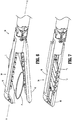
- the first jaw 40 and/or the second jaw 50 is pivotable with respect to the proximal body portion 32 of the end effector 30 such that the first and second jaws 40, 50 are movable between an open or unclamped position in which the first and second jaws 40, 50 are spaced apart with respect to each other (see e.g., FIG. 6 ) and a closed or clamped position in which the first and second jaws 40, 50 are substantially adjacent each other (see e.g., FIG. 7 ).
- the handle assembly 10 includes a stationary handle portion 12a, a movable handle portion or trigger 12b, and a barrel portion 14.
- a rotatable member 16 is mounted on the forward end of the barrel portion 14 to facilitate rotation of the elongate body portion 20 and thus, the end effector 30 with respect to the handle assembly 10 so as to properly orient the jaw assembly 34 relative to tissue to be sutured.
- An articulation lever 18 is also mounted on the forward end of the barrel portion 14 to facilitate articulation of the jaw assembly 30.
- a retraction knob 19 is movably positionable along the barrel portion 14 to open and/or close the first and second jaws 40, 50, relative to each other. Actuation of the trigger 12b applies a purse string suture 66 (see e.g., FIG. 9A ) to tissue captured between the first and second jaws 40, 50, as described in further detail below.
- the first jaw 40 of the jaw assembly 34 includes a tissue facing surface 42 having a central longitudinal slot 41 formed therein and extending along a central longitudinal axis "X" of the end effector 30.
- the first jaw 40 further includes an elongated rail 44 and a longitudinal row of teeth 46 extending outwardly from the tissue facing surface 42 towards the second jaw 50.
- the elongated rail 44 and the teeth 46 are disposed on opposed sides of the central longitudinal slot 41 in substantially parallel relation relative to one another.
- the elongated rail 44 and the teeth 46 extend longitudinally along the tissue facing surface 42 in laterally spaced relation relative to the central longitudinal slot 41 such that the elongated rail 44 and the teeth 46 are laterally offset from the central longitudinal axis "X" of the end effector 30.
- the elongated rail 44 is a continuous uninterrupted block of biocompatible material having an outer or tissue clamping surface 44a.
- the tissue clamping surface 44a of the elongated rail 44 may be textured (e.g., grooved, roughened, etc.) to enhance the grip of the tissue clamping surface 44a to tissue. While the elongated rail 44 is shown as having a generally rectangular shape, it should be understood that the elongated rail 44 may be any shape, such as semi-circular shape, so long as the elongated rail 44 is dimensioned to grasp tissue between the first and second jaws 40, 50, as described in further detail below, when the jaw assembly 34 is moved to the closed position.
- the teeth 46 are separate blocks of biocompatible material disposed in axially spaced relation relative to each other and each having an outer or tissue engaging surface 46a.
- the tissue engaging surface 46a may be textured (e.g., grooved, roughened, etc.) to enhance the grip of the tissue engaging surface 46a to tissue.
- Each tooth 46 includes a needle channel 47a defined therethrough, and a slit 47b extending between the needle channel 47a and the tissue engaging surface 46a.
- the needle channels 47a and the slits 47b of the teeth 46 are longitudinally aligned along the length of the first jaw 40.
- the needle channels 47a are sized and shaped for slidable movement of a needle therethrough, and the slits 47b are sized and shaped for passage of a suture therethrough.
- teeth 46 are shown as having a generally square or rectangular shape, it should be understood that the teeth 46 may be any shape, such as cylindrical pegs, so long as the teeth 46 are arranged to allow for tissue disposed therebetween to take on a sinuous or wave-like configuration, as described in further detail below, when the jaw assembly 34 is moved to the closed position.
- the teeth 46 may be formed from one or more blocks of biocompatible material that are cut to include undulations (e.g., curves or steps) forming the teeth 46 and the spaces therebetween.
- the first jaw 40 further includes a tip portion 48 at a distal end thereof.
- the tip portion 48 is curved to enhance visualization and/or maneuverability of the jaw assembly 34 around target tissue.
- the tip portion 48 of the first jaw 40 may aid in tissue manipulation, allowing for blunt dissection and/or mobilization.
- Other configurations of the tip portion 48 are envisioned depending upon, for example, the desired characteristics of the jaw assembly 34 as should be understood by those skilled in the art.
- the tip portion 48 includes an upper or first aperture 49a and a lower or second aperture 49b defined therethrough.
- the first and second apertures 49a, 49b are longitudinally oriented and aligned with the needle channels 47a, 57a of the first and second jaws 40, 50, respectively.
- the first and second apertures 49a, 49b are configured for passage of needles longitudinally therethrough.
- the first and second apertures 49a, 49b are defined by a semi-continuous surface having a generally c-shaped configuration and are open at an outer side surface 48a of the tip portion 48 to allow for passage of a suture, but not the needle, therethrough.
- the first aperture 49a of the tip portion 48 is axially aligned with or in registration with the needle channels 47a of the teeth 46 of the first jaw 40. Further, when the jaw assembly 34 is closed, as seen in FIGS. 7 and 10 , the second aperture 49b of the tip portion 48 is axially aligned with or in registration with the needle channels 57a of the teeth 56 of the second jaw 50, as described in detail below.
- the second jaw 50 of the jaw assembly 34 includes a tissue facing surface 52 having a central longitudinal slot 51 formed therein, and an elongated rail 54 and a longitudinal row of teeth 56 extending outwardly from the tissue facing surface 52 towards the first jaw 40.
- the structure and relative positioning of the central longitudinal slot 51, the elongated rail 54, and the teeth 56 of the second jaw 50 are substantially the same as the central longitudinal slot 41, the elongate rail 44, and the teeth 46 of the first jaw 40.
- the central longitudinal slot 51 extends along the central longitudinal axis "X" of the end effector 30, and the elongated rail 44 and the teeth 46 are disposed on opposed sides of the central longitudinal slot 51 in substantially parallel relation relative to one another.
- the elongated rail 54 and the teeth 56 extend longitudinally along the tissue facing surface 52 in laterally spaced relation relative to the central longitudinal slot 51 such that the elongated rail 54 and the teeth 56 are laterally offset from the central longitudinal axis "X" of the end effector 30.
- the elongated rail 54 is a continuous uninterrupted block of biocompatible material having an outer or tissue clamping surface 54a.
- the tissue clamping surface 54a of the elongated rail 54 may be textured (e.g., grooved, roughened, etc.) to enhance the grip of the tissue clamping surface 54a to tissue.
- the size and shape of the elongated rail 54 may vary, as discussed above with regard to the elongated rail 44 of the first jaw 40.
- the teeth 56 are separate blocks of biocompatible material disposed in axially spaced relation relative to each other and each having an outer or tissue engaging surface 56a.
- the tissue engaging surface 56a may be textured (e.g., grooved, roughened, etc.) to enhance the grip of the tissue engaging surface 56a to tissue.
- Each tooth 56 includes a needle channel 57a defined therethrough, and a slit 57b extending between the needle channel 57a and the tissue engaging surface 56a.
- the needle channels 57a and the slits 57b of the teeth 56 are longitudinally aligned along the length of the second jaw 50.
- the needle channels 57a are sized and shaped to allow for slidable movement of a needle therethrough, and the slits 57b are sized and shaped to allow for passage of a suture therethrough.
- the size, shape, and/or formation of the teeth 56 may vary, as discussed above with regard to the teeth 46 of the first jaw 40.
- the tissue facing surface 52 of the second jaw 50 is a mirror image of the tissue facing surface 42 of the first jaw 40. Accordingly, the tissue facing surfaces 42, 52 of the first and second jaws 40, 50 are disposed in opposed relation relative to each other such that the central longitudinal slot 41 of the first jaw 40 opposes and is aligned with the central longitudinal slot 51 of the second jaw 50, the elongated rail 44 of the first jaw 40 opposes and is aligned with the elongated rail 54 of the second jaw 50, and the teeth 46 of the first jaw 40 oppose and are aligned with the teeth 56 of the second jaw 50.
- a needle assembly 60 is slidably disposed within the end effector 30.
- the needle assembly 60 includes first and second needles 62, 64 configured and dimensioned to move through the needle channels 47a, 57a of the teeth 46, 56 of the first and second jaws 40, 50, respectively.
- Each of the first and second needles 62, 64 includes an elongate body 62a, 64a including a proximal end portion 62b, 64b operably coupled to a needle pusher 13 ( FIG. 8B ) of the handle assembly 10 for effecting longitudinal movement of the first and second needles 62, 64, and a sharp distal tip portion 62c, 64c for piercing tissue.
- the distal tip portions 62c, 64c of the first and second needles 62, 64 each include a transverse hole 63a, 65a defined therethrough, and a passageway 63b, 65b extending between the transverse hole 63a, 65a and an outer surface of the needle 62, 64.
- a suture 66 is coupled to or threaded in the distal tip portions 62c, 64c of the first and second needles 62, 64.
- a first end portion 66a of the suture 66 is passed through the transverse hole 63a of the first needle 62 and a second end portion 66b of the suture 66 is passed through the transverse hole 65a of the second needle 64 such that a central portion 66c of the suture 66, which is disposed between the first and second end portions 66a, 66b, is free and extends proximally along the first and second needles 62, 64 (e.g., disposed within a proximal portion of the jaw assembly 34).
- the first and second needles 62, 64 and the suture 66 are formed from biocompatible materials which are bioabsorbable or non-absorbable, natural or synthetic, or combinations thereof.
- the first and second needles 62, 64 may be straight needles formed from a surgical grade metal, and/or the suture 66 may be a monofilament suture formed from a non-absorbable material. It should be understood, however, that the materials and configuration of the first and second needles 62, 64 and the suture 66 may vary.
- the end effector 30 includes a mounting assembly 70 pivotably coupling the proximal body portion 32 to the jaw assembly 34.
- the mounting assembly 70 includes an upper mounting member 72 and a lower mounting member 74.
- the upper mounting member 72 is fixedly secured to the lower mounting member 74 and the first jaw 40, and the lower mounting member 74 is pivotally secured to the second jaw 50.
- Coupling members 76 extend distally from the lower mounting member 74 for rotatably securing the mounting assembly 70 to the proximal body portion 32 of the end effector 30.
- the lower mounting member 74 includes a pair of extensions 74a extending proximally into the second jaw 50.
- One extension of the pair of extensions 74a includes an upper or first opening 75a and a lower or second opening 75b extending longitudinally therethrough.
- the first and second openings 75a, 75b are aligned with the needle channels 47a, 57a of the first and second jaws 40, 50, respectively, when the first and second jaws 40, 50 are disposed in the closed position.
- the first and second openings 75a, 75b are configured and dimensioned for slidable passage of the first and second needles 62, 64 therethrough.
- first and second needles 62, 64 can travel, respectively, through the first and second openings 75a, 75b of the mounting assembly 70 and into the needle channels 47a, 57a of the teeth 46, 56 of the respective first and second jaws 40, 50, to suture tissue disposed therebetween.
- the end effector 30 further includes a drive assembly 80 operably associated with and slidably disposed between the first and second jaws 40, 50 of the jaw assembly 34.
- the drive assembly 80 includes an elongated drive beam 82 having a connector 83 at a proximal end thereof that is configured to releasably engage a drive member or firing rod 11 ( FIG. 8B ) of the handle assembly 10, and an I-beam 84 at a distal end thereof.
- the I-beam 84 includes an upper or first beam 84a, a lower or second beam 84b, and a vertical strut 84c interconnecting the first and second beams 84a, 84b.
- a knife 86 is formed on a distal face of the vertical strut 84c.
- the first and second beams 84a, 84b of the I-beam 84 can travel along the first and second jaws 40, 50 to move the first and second jaws 40, 50 to the closed position while the knife 86 travels between the elongated rails 44, 54 and the teeth 46, 56 of the respective tissue facing surfaces 42, 52, to longitudinally cut tissue disposed therebetween.
- the end effector 30, which is loaded with the needle assembly 60 and secured to the distal end of the elongate body portion 20, is inserted through an access device (not shown), such as a trocar, a cannula, or an access port, and positioned at a desired surgical site.
- Tissue "T” is placed between the first and second jaws 40, 50 of the end effector 30, as shown in FIG. 6 , with an opening “P" defined through the tissue “T” positioned substantially perpendicular to the central longitudinal axis "X" of the end effector 30 and the open end “E” of the tissue “T” extending laterally adjacent to the side of the end effector 30 including the elongated rails 44, 54 ( FIG. 3 ).
- the jaw assembly 34 is moved from the open position, shown in FIG. 6 , to the closed position, shown in FIG. 7 , to clamp the tissue "T" between the first and second jaws 40, 50.
- the elongated rails 44, 54 of the first and second jaws 40, 50 grip the tissue “T” to prevent slippage of the tissue “T” from the jaw assembly 34 and to uniformly compress the opening "P" in the tissue “T” closed.
- the portion of the tissue “T” disposed between the teeth 46, 56 of the first and second jaws 40, 50 take on a wave-like configuration including tissue portions "T1" compressed together between the tissue engaging surfaces 46a, 56a of the teeth 46, 56 and tissue portions "T2" spread apart (e.g., bulging, protruding, etc.) and bowed into the space defined between adjacent teeth 46, 56.
- the surgical suturing device 1 is then fired by actuating the trigger 12b of the handle assembly 10.
- the needle assembly 60 as well as the drive assembly 80 of the end effector 30 are advanced distally through the jaw assembly 34 from a first or retracted position to a second or advanced position. Specifically, as shown in FIGS.
- the elongate bodies 62a, 64a of the first and second needles 62, 64 of the needle assembly 60 extend through the first and second openings 75a, 75b, respectively, of the mounting assembly 70 with the proximal end portions 62b, 64b abutting a distal face 13a of the needle pusher 13 and the distal tip portions 62c, 64c disposed proximal of the teeth 46, 56 of the first and second jaws 40, 50.
- the firing rod 11, which is secured to the elongated drive beam 82 at the connector 83, and the needle pusher 13, which is secured (e.g., welded) to and extends laterally from the firing rod 11, are advanced distally to drive or push the elongated drive beam 82 and the first and second needles 62, 64 distally.
- the first and second needles 62, 64 pass, respectively, through the needle channels 47a, 57a of the teeth 46, 56 and through the tissue portions "T2" disposed in the space between adjacent teeth 46, 56.
- the suture 66 is also passed through the needle channels 47a, 57a of the teeth 46, 56 and the tissue portions "T2" disposed between the teeth 46, 56.
- the firm grasp of the tissue engaging surfaces 46a, 56a of the teeth 46, 56 on the tissue "T” allows the needle assembly 60 to penetrate and stitch the tissue portions "T2" disposed between the teeth 46, 56.
- the elongated drive beam 82 of the drive assembly 80 passes through the central longitudinal slots 41, 51 ( FIG. 5 ) of the first and second jaws 40, 50 with the knife 86 ( FIG.
- the needle assembly 60 and the drive assembly 80 are advanced distally through the full firing stroke of the trigger 12b such that at the end of the firing stroke, the distal tip portions 62c, 64c of the first and second needles 62, 64 pass through the respective first and second apertures 49a, 49b of the tip portion 48 of the first jaw 40, as shown in FIG. 10 .
- the first and second end portions 66a, 66b of the suture 66 are grasped by grasping instruments 2.
- the needle assembly 60 and the drive assembly 80 are then retracted proximally and the first and second jaws 40, 50 are opened (e.g., via the retraction knob 19 of the handle assembly 10) so that the surgical suturing device 1 can be removed from the now sutured tissue "T.”
- the needle pusher 13 may include apertures (not explicitly shown) disposed in the distal face 13a thereof that frictionally and yet releasably engage the proximal end portions 62b, 64b of the first and second needles 62, 64 such that when the firing rod 13 is retracted proximally, the first and second needles 62, 64 are also retracted proximally, and when the end effector 30 is detached from the handle assembly 10, the needle pusher 13 releases the first and second needles 62, 64.
- the suture 66 passes through the passageways 63b, 65b of the first and second needles 62, 64 so that only the first and second needles 62, 64 are retracted and the suture 66 is retained in the needle channels 47a, 57a of the teeth 46, 56 of the first and second jaws 40, 50, as well as through the tissue "T" disposed between adjacent teeth 46, 56.
- the suture 66 is freed from the jaw assembly 34 by passing through the slits 47b, 57b of the teeth 46, 56 as well as the open side of the tip portion 48, leaving the suture 66 attached to the tissue "T" around the perimeter thereof, as shown in FIG. 11 .
- the first and second end portions 66a, 66b of the suture 66 are then pulled to tighten the suture 66 and narrow the opening "P" defined in the tissue "T,” such as around an anvil or cartridge assembly (not shown) of a circular stapler.
- end effector 30 is shown as including a drive assembly 80 having a knife 86, it should be understood that the drive assembly 80 may be modified to omit the knife 86 such that the surgical suturing device 1 does not cut tissue.
- the end effector 30 of the present disclosure may be a single use end effector 30 that is pre-loaded with the needle assembly 60, with or without the suture 66, during manufacture of the end effector 30.
- the end effector 30 may be reusable.
- the first and second needles 62, 64 of the needle assembly 60 may be a fixed, permanent component of the end effector 30 or an interchangeable, releasably engaged part thereof, and/or the suture 66 may be a replaceable component of the end effector 30.
- end effectors 30 described herein may also be configured for use with other surgical apparatus, such as electromechanical surgical devices as described, for example, in U.S. Patent Appl. Pub. Nos. 2015/0157320 and 2015/0157321 , the entire contents of each of which are incorporated herein by reference.
Landscapes
- Health & Medical Sciences (AREA)
- Surgery (AREA)
- Life Sciences & Earth Sciences (AREA)
- Biomedical Technology (AREA)
- Nuclear Medicine, Radiotherapy & Molecular Imaging (AREA)
- Engineering & Computer Science (AREA)
- Heart & Thoracic Surgery (AREA)
- Medical Informatics (AREA)
- Molecular Biology (AREA)
- Animal Behavior & Ethology (AREA)
- General Health & Medical Sciences (AREA)
- Public Health (AREA)
- Veterinary Medicine (AREA)
- Ophthalmology & Optometry (AREA)
- Surgical Instruments (AREA)
Abstract
Description
- This application claims the benefit of and priority to
U.S. Provisional Patent Application No. 62/744,147 filed October 11, 2018 - The present disclosure relates to surgical devices and methods of using the same. More particularly, the present disclosure relates to endoscopic surgical devices for affixing purse string sutures to tissue.
- Surgical stapling apparatus are employed by surgeons to sequentially or simultaneously apply one or more rows of fasteners, e.g., staples or two-part fasteners, to body tissue for the purpose of joining segments of body tissue together and/or creating anastomoses.
- Annular surgical stapling apparatus generally include a staple cartridge assembly including annular rows of staples, an anvil assembly operatively associated with the staple cartridge assembly, and an annular blade disposed internal to the annular rows of staples. In use, during an end-to-end circular anastomosis procedure, two ends of hollow tissue sections (e.g., bowels, intestines, or other tubular organs) are positioned between the anvil and staple cartridge assemblies and are joined by clamping the two ends together and driving the annular rows of staples through the clamped tissue sections. During firing of the staples, the annular blade is advanced to cut portions of the tissue sections extending inside the staple lines, thereby establishing a passage through the two stapled tissue sections.
- The ends of the tissue sections may be secured over the anvil and staple cartridge assemblies by purse string sutures prior to approximating the anvil assembly relative to the staple cartridge assembly. Purse string sutures are utilized to close or narrow the openings or passages of the tissue sections. A suture is typically passed through the tissue section as a running stitch, in and out around the end of the tissue section, using a needle, staples, and/or an extracorporeal device for attaching the suture to tissue. After the tissue is stitched, the ends of the suture are brought together and pulled tight to close or narrow the opening in the tissue section. The ends of the suture may then be tied together.
- For example, in laparoscopic gastrointestinal end-to-end anastomosis, a surgeon may create an external incision to bring a target tissue section (e.g., intestine or colon) outside of the body, and attach a purse string suture to the tissue section using an extracorporeal device. Such a procedure, however, may cause complications, like bleeding, injury, or increased surgical and/or recovery time.
- The present disclosure is directed to a surgical device for placing purse string sutures in tissue within the body (e.g., intra-peritoneal space) without creating an external incision or using staples.
- According to an aspect of the present disclosure, a surgical suturing device includes an end effector including a jaw assembly and a needle assembly. The jaw assembly includes first and second jaws movable between an open position and a closed position. Each of the first and second jaws includes a tissue facing surface having an elongated rail and a longitudinal row of teeth. Each tooth of the longitudinal rows of teeth of the first and second jaws includes a needle channel extending therethrough. The elongated rails and the longitudinal rows of teeth of the first and second jaws are disposed in opposed relation relative to each other. The needle assembly includes a first needle, a second needle, and a suture coupled to the first and second needles. The first needle is slidable through the needle channels of the longitudinal row of teeth of the first jaw and the second needle is slidable through the needle channels of the longitudinal row of teeth of the second jaw.
- Each of the tissue facing surfaces of the first and second jaws may include a central longitudinal slot defined therein. The elongate rail and the longitudinal row of teeth of each of the first and second jaws may be disposed on opposed sides of the central longitudinal slot of the respective first or second jaw.
- Each of the elongated rails of the first and second jaws may include a tissue clamping surface. The tissue clamping surfaces may be configured to grasp tissue therebetween when the jaw assembly is in the closed position. Each tooth of the longitudinal rows of teeth of the first and second jaws may include a tissue engaging surface. The tissue engaging surfaces may be configured to grasp tissue therebetween when the jaw assembly is in the closed position. Each tooth of the longitudinal rows of teeth of the first and second jaws may have a slit defined therein that extends between the needle channel and an outer surface of the tooth.
- The first jaw may include a tip portion having first and second apertures extending therethrough. The first aperture may be aligned with the needle channels of the first jaw and the second aperture may be aligned with the needle channels of the second jaw when the jaw assembly is disposed in the closed position. Each of the first and second apertures of the tip portion may be defined by a semi-continuous surface such that the first and second apertures are open at an outer side surface of the tip portion.
- Each of the first and second needles of the needle assembly may include a distal tip portion having a transverse hole extending therethrough. A first end portion of the suture may extend through the transverse hole of the first needle and a second end portion of the suture may extend through the transverse hole of the second needle. Each of the first and second needles may include a passageway extending between the transverse hole and an outer surface of the respective first or second needle.
- The end effector may further include a proximal body portion and a mounting assembly pivotably coupling the proximal body portion to the jaw assembly. The mounting assembly may include first and second openings extending longitudinally therethrough that are aligned with the needle channels of the first and second jaws when the first and second jaws are in the closed position. The first and second openings may be configured for passage of the first and second needles therethrough.
- The end effector may further include a drive assembly including an elongated drive beam and a knife. The knife may be movable through the central longitudinal slots of the first and second jaws.
- The surgical suturing device may further include a handle assembly and an elongate body extending distally from the handle assembly. The end effector may extend distally from the elongate body portion.
- According to another aspect of the present disclosure, a method of securing a purse string suture to tissue includes: positioning tissue between tissue facing surfaces of first and second jaws of an end effector of a surgical suturing device, each of the tissue facing surfaces of the first and second jaws including an elongated rail and a longitudinal row of teeth, each tooth of the longitudinal rows of teeth including a needle channel extending therethrough; closing the first and second jaws such that the tissue is clamped between the elongated rails of the first and second jaws and takes on a wave-like configuration between the longitudinal rows of teeth, the wave-like configuration including first tissue portions compressed together between opposed teeth of the longitudinal rows of teeth and second tissue portions spread apart and bowed into the spaces defined between adjacent teeth of each of the longitudinal rows of teeth; and actuating the surgical suturing device to advance a needle assembly of the end effector distally through the jaw assembly to suture the tissue disposed therebetween, the needle assembly including a suture coupled to first and second needles, the first and second needles slidable through the needle channels of the longitudinal rows of teeth of the first and second jaws and the tissue disposed in the spaces between adjacent teeth of the longitudinal rows of teeth.
- Actuating the surgical suturing device may further include advancing a drive assembly of the end effector distally through the jaw assembly to cut the tissue disposed between the first and second jaws.
- Actuating the surgical suturing device may include advancing distal tip portions of the first and second needles through first and second apertures defined in a tip portion of the first jaw. The method may further include grasping first and second end portions of the suture with grasping instruments. The method may further include retracting the needle assembly proximally into a proximal body portion of the end effector and opening the first and second jaws such that the suture passes through slits defined in each tooth of the longitudinal rows of teeth as well as an open side of the tip portion, leaving the suture attached to the tissue around a perimeter thereof.
- Other aspects, features, and advantages will be apparent from the description, drawings, and the claims.
- Various aspects of the present disclosure are described herein below with reference to the drawings, which are incorporated in and constitute a part of this specification, wherein:
-
FIG. 1 is a side, perspective view of a surgical suturing device in accordance with an embodiment of the present disclosure; -
FIGS. 2 and3 are enlarged, perspective views of a jaw assembly of an end effector of the surgical suturing device ofFIG. 1 ; -
FIG. 4 is a side view of a needle assembly of the end effector ofFIGS. 1-3 ; -
FIG. 5 is an exploded, perspective view of the jaw assembly ofFIGS. 1-3 ; -
FIG. 6 is a side, perspective view of a jaw assembly of an end effector of the surgical suturing device ofFIG. 1 , shown in an open position with tissue positioned between first and second jaws of the jaw assembly during a surgical suturing procedure in accordance with an embodiment of the present disclosure; -
FIG. 7 is a side, perspective view of the jaw assembly of the end effector ofFIG. 6 , shown in a closed position with the tissue clamped between the first and second jaws; -
FIG. 8A is a side, close-up view of the end effector ofFIG. 7 , showing the first and second jaws in phantom, and illustrating distal portions of a needle assembly and a drive assembly of the end effector, prior to firing the surgical suturing device; -
FIG. 8B is a side, close-up view of the end effector ofFIG. 7 , illustrating proximal portions of a needle assembly and a drive assembly of the end effector prior to firing the surgical suturing device; -
FIG. 9A is a side, close-up view of the end effector and the tissue ofFIG. 7 , during actuation of a firing stroke of the surgical suturing device; -
FIG. 9B is a top, close-up view of the end effector and the tissue ofFIG. 7 , showing the first jaw in phantom, during actuation of a firing stroke the surgical suturing device; -
FIG. 10 is a side, perspective view of the end effector and the tissue ofFIGS. 9A and9B , at the end of the firing stroke of the surgical suturing device; and -
FIG. 11 is a side, perspective view of the tissue ofFIGS. 6-10 after performing the surgical suturing procedure. - Various exemplary embodiments of the present disclosure are discussed herein below in terms of surgical devices for securing sutures to tissue. The surgical devices described herein may be used to apply a suture to a hollow or tubular tissue section (also referred to herein, generally, as tissue) by grasping an end portion of the tissue between first and second jaws of the surgical device in a wave-like configuration and passing the suture therethrough.
- Embodiments of the presently disclosed surgical suturing devices will now be described in detail with reference to the drawing figures wherein like reference numerals identify similar or identical elements. Throughout this description, the term "proximal" refers to a portion of a device, or component thereof, that is closer to a user, and the term "distal" refers to a portion of the device, or component thereof, that is farther from the user. Directional reference terms, such as "upper," "lower," "top," "bottom," "side," and the like, are intended to ease description of the embodiments and are not intended to have any limiting effect on the ultimate orientation of a device or any parts thereof.
- Referring now to
FIG. 1 , an exemplary surgical purse string suture device or surgical suturing device 1 is shown for applying purse string sutures to tissue. The surgical suturing device 1 generally includes ahandle assembly 10, anelongate body portion 20 extending distally from thehandle assembly 10, and anend effector 30 extending distally from theelongate body portion 20. Theend effector 30 includes aproximal body portion 32 and ajaw assembly 34 pivotably attached to theproximal body portion 32. Theend effector 30 may be releasably secured to theelongate body portion 20 such that theend effector 30 is replaceable with anew end effector 30, or theend effector 30 may be permanently affixed to theelongate body portion 20. - The
jaw assembly 34 includes an upper orfirst jaw 40 and a lower orsecond jaw 50 disposed in opposed relation to thefirst jaw 40. Thefirst jaw 40 and/or thesecond jaw 50 is pivotable with respect to theproximal body portion 32 of theend effector 30 such that the first andsecond jaws second jaws FIG. 6 ) and a closed or clamped position in which the first andsecond jaws FIG. 7 ). - The
handle assembly 10 includes astationary handle portion 12a, a movable handle portion ortrigger 12b, and abarrel portion 14. Arotatable member 16 is mounted on the forward end of thebarrel portion 14 to facilitate rotation of theelongate body portion 20 and thus, theend effector 30 with respect to thehandle assembly 10 so as to properly orient thejaw assembly 34 relative to tissue to be sutured. Anarticulation lever 18 is also mounted on the forward end of thebarrel portion 14 to facilitate articulation of thejaw assembly 30. Aretraction knob 19 is movably positionable along thebarrel portion 14 to open and/or close the first andsecond jaws trigger 12b applies a purse string suture 66 (see e.g.,FIG. 9A ) to tissue captured between the first andsecond jaws - For a detailed description of the structure and function of exemplary handle assemblies or components thereof suitable for use in a surgical suturing device of the present disclosure, reference may be made to
U.S. Patent Nos. 6,330,965 ,6,241,139 ,7,819,896 ,7,128,253 , and8,931,679 , the entire contents of each of which are incorporated herein by reference. - Turning now to
FIGS. 2 and3 , thefirst jaw 40 of thejaw assembly 34 includes atissue facing surface 42 having a centrallongitudinal slot 41 formed therein and extending along a central longitudinal axis "X" of theend effector 30. Thefirst jaw 40 further includes anelongated rail 44 and a longitudinal row ofteeth 46 extending outwardly from thetissue facing surface 42 towards thesecond jaw 50. Theelongated rail 44 and theteeth 46 are disposed on opposed sides of the centrallongitudinal slot 41 in substantially parallel relation relative to one another. Theelongated rail 44 and theteeth 46 extend longitudinally along thetissue facing surface 42 in laterally spaced relation relative to the centrallongitudinal slot 41 such that theelongated rail 44 and theteeth 46 are laterally offset from the central longitudinal axis "X" of theend effector 30. - The
elongated rail 44 is a continuous uninterrupted block of biocompatible material having an outer ortissue clamping surface 44a. Thetissue clamping surface 44a of theelongated rail 44 may be textured (e.g., grooved, roughened, etc.) to enhance the grip of thetissue clamping surface 44a to tissue. While theelongated rail 44 is shown as having a generally rectangular shape, it should be understood that theelongated rail 44 may be any shape, such as semi-circular shape, so long as theelongated rail 44 is dimensioned to grasp tissue between the first andsecond jaws jaw assembly 34 is moved to the closed position. - The
teeth 46 are separate blocks of biocompatible material disposed in axially spaced relation relative to each other and each having an outer ortissue engaging surface 46a. Thetissue engaging surface 46a may be textured (e.g., grooved, roughened, etc.) to enhance the grip of thetissue engaging surface 46a to tissue. Eachtooth 46 includes aneedle channel 47a defined therethrough, and aslit 47b extending between theneedle channel 47a and thetissue engaging surface 46a. Theneedle channels 47a and theslits 47b of theteeth 46 are longitudinally aligned along the length of thefirst jaw 40. Theneedle channels 47a are sized and shaped for slidable movement of a needle therethrough, and theslits 47b are sized and shaped for passage of a suture therethrough. - While the
teeth 46 are shown as having a generally square or rectangular shape, it should be understood that theteeth 46 may be any shape, such as cylindrical pegs, so long as theteeth 46 are arranged to allow for tissue disposed therebetween to take on a sinuous or wave-like configuration, as described in further detail below, when thejaw assembly 34 is moved to the closed position. Alternatively, theteeth 46 may be formed from one or more blocks of biocompatible material that are cut to include undulations (e.g., curves or steps) forming theteeth 46 and the spaces therebetween. - The
first jaw 40 further includes atip portion 48 at a distal end thereof. Thetip portion 48 is curved to enhance visualization and/or maneuverability of thejaw assembly 34 around target tissue. Thetip portion 48 of thefirst jaw 40 may aid in tissue manipulation, allowing for blunt dissection and/or mobilization. Other configurations of thetip portion 48 are envisioned depending upon, for example, the desired characteristics of thejaw assembly 34 as should be understood by those skilled in the art. Whenjaw assembly 34 is closed, as seen inFIGS. 7 and10 , thetip portion 48 of thefirst jaw 40 extends at least partially into or across thesecond jaw 50. - The
tip portion 48 includes an upper orfirst aperture 49a and a lower orsecond aperture 49b defined therethrough. The first andsecond apertures needle channels second jaws second apertures FIG. 2 , the first andsecond apertures outer side surface 48a of thetip portion 48 to allow for passage of a suture, but not the needle, therethrough. Thefirst aperture 49a of thetip portion 48 is axially aligned with or in registration with theneedle channels 47a of theteeth 46 of thefirst jaw 40. Further, when thejaw assembly 34 is closed, as seen inFIGS. 7 and10 , thesecond aperture 49b of thetip portion 48 is axially aligned with or in registration with theneedle channels 57a of theteeth 56 of thesecond jaw 50, as described in detail below. - With continued reference to
FIG. 2 , thesecond jaw 50 of thejaw assembly 34 includes atissue facing surface 52 having a centrallongitudinal slot 51 formed therein, and anelongated rail 54 and a longitudinal row ofteeth 56 extending outwardly from thetissue facing surface 52 towards thefirst jaw 40. The structure and relative positioning of the centrallongitudinal slot 51, theelongated rail 54, and theteeth 56 of thesecond jaw 50 are substantially the same as the centrallongitudinal slot 41, theelongate rail 44, and theteeth 46 of thefirst jaw 40. - Specifically, the central
longitudinal slot 51 extends along the central longitudinal axis "X" of theend effector 30, and theelongated rail 44 and theteeth 46 are disposed on opposed sides of the centrallongitudinal slot 51 in substantially parallel relation relative to one another. Theelongated rail 54 and theteeth 56 extend longitudinally along thetissue facing surface 52 in laterally spaced relation relative to the centrallongitudinal slot 51 such that theelongated rail 54 and theteeth 56 are laterally offset from the central longitudinal axis "X" of theend effector 30. - The
elongated rail 54 is a continuous uninterrupted block of biocompatible material having an outer ortissue clamping surface 54a. Thetissue clamping surface 54a of theelongated rail 54 may be textured (e.g., grooved, roughened, etc.) to enhance the grip of thetissue clamping surface 54a to tissue. The size and shape of theelongated rail 54 may vary, as discussed above with regard to theelongated rail 44 of thefirst jaw 40. - The
teeth 56 are separate blocks of biocompatible material disposed in axially spaced relation relative to each other and each having an outer ortissue engaging surface 56a. Thetissue engaging surface 56a may be textured (e.g., grooved, roughened, etc.) to enhance the grip of thetissue engaging surface 56a to tissue. Eachtooth 56 includes aneedle channel 57a defined therethrough, and aslit 57b extending between theneedle channel 57a and thetissue engaging surface 56a. Theneedle channels 57a and theslits 57b of theteeth 56 are longitudinally aligned along the length of thesecond jaw 50. Theneedle channels 57a are sized and shaped to allow for slidable movement of a needle therethrough, and theslits 57b are sized and shaped to allow for passage of a suture therethrough. The size, shape, and/or formation of theteeth 56 may vary, as discussed above with regard to theteeth 46 of thefirst jaw 40. - The
tissue facing surface 52 of thesecond jaw 50 is a mirror image of thetissue facing surface 42 of thefirst jaw 40. Accordingly, the tissue facing surfaces 42, 52 of the first andsecond jaws longitudinal slot 41 of thefirst jaw 40 opposes and is aligned with the centrallongitudinal slot 51 of thesecond jaw 50, theelongated rail 44 of thefirst jaw 40 opposes and is aligned with theelongated rail 54 of thesecond jaw 50, and theteeth 46 of thefirst jaw 40 oppose and are aligned with theteeth 56 of thesecond jaw 50. - As shown in
FIGS. 4 and5 , aneedle assembly 60 is slidably disposed within theend effector 30. Theneedle assembly 60 includes first andsecond needles needle channels teeth second jaws second needles elongate body proximal end portion FIG. 8B ) of thehandle assembly 10 for effecting longitudinal movement of the first andsecond needles distal tip portion - The
distal tip portions second needles transverse hole passageway transverse hole needle suture 66 is coupled to or threaded in thedistal tip portions second needles first end portion 66a of thesuture 66 is passed through thetransverse hole 63a of thefirst needle 62 and asecond end portion 66b of thesuture 66 is passed through thetransverse hole 65a of thesecond needle 64 such that acentral portion 66c of thesuture 66, which is disposed between the first andsecond end portions second needles 62, 64 (e.g., disposed within a proximal portion of the jaw assembly 34). - The first and
second needles suture 66 are formed from biocompatible materials which are bioabsorbable or non-absorbable, natural or synthetic, or combinations thereof. The first andsecond needles suture 66 may be a monofilament suture formed from a non-absorbable material. It should be understood, however, that the materials and configuration of the first andsecond needles suture 66 may vary. - With continued reference to
FIG. 5 , in conjunction withFIG. 1 , theend effector 30 includes a mountingassembly 70 pivotably coupling theproximal body portion 32 to thejaw assembly 34. The mountingassembly 70 includes an upper mountingmember 72 and a lower mountingmember 74. The upper mountingmember 72 is fixedly secured to the lower mountingmember 74 and thefirst jaw 40, and the lower mountingmember 74 is pivotally secured to thesecond jaw 50. Couplingmembers 76 extend distally from the lower mountingmember 74 for rotatably securing the mountingassembly 70 to theproximal body portion 32 of theend effector 30. - The lower mounting
member 74 includes a pair ofextensions 74a extending proximally into thesecond jaw 50. One extension of the pair ofextensions 74a includes an upper orfirst opening 75a and a lower orsecond opening 75b extending longitudinally therethrough. The first andsecond openings needle channels second jaws second jaws second openings second needles second needles second openings assembly 70 and into theneedle channels teeth second jaws - The
end effector 30 further includes adrive assembly 80 operably associated with and slidably disposed between the first andsecond jaws jaw assembly 34. Thedrive assembly 80 includes anelongated drive beam 82 having aconnector 83 at a proximal end thereof that is configured to releasably engage a drive member or firing rod 11 (FIG. 8B ) of thehandle assembly 10, and an I-beam 84 at a distal end thereof. The I-beam 84 includes an upper orfirst beam 84a, a lower orsecond beam 84b, and avertical strut 84c interconnecting the first andsecond beams knife 86 is formed on a distal face of thevertical strut 84c. The first andsecond beams beam 84 can travel along the first andsecond jaws second jaws knife 86 travels between theelongated rails teeth - To use the surgical suturing device 1, the
end effector 30, which is loaded with theneedle assembly 60 and secured to the distal end of theelongate body portion 20, is inserted through an access device (not shown), such as a trocar, a cannula, or an access port, and positioned at a desired surgical site. Tissue "T" is placed between the first andsecond jaws end effector 30, as shown inFIG. 6 , with an opening "P" defined through the tissue "T" positioned substantially perpendicular to the central longitudinal axis "X" of theend effector 30 and the open end "E" of the tissue "T" extending laterally adjacent to the side of theend effector 30 including the elongated rails 44, 54 (FIG. 3 ). Once properly oriented and positioned, thejaw assembly 34 is moved from the open position, shown inFIG. 6 , to the closed position, shown inFIG. 7 , to clamp the tissue "T" between the first andsecond jaws - In the closed position, the
elongated rails second jaws jaw assembly 34 and to uniformly compress the opening "P" in the tissue "T" closed. The portion of the tissue "T" disposed between theteeth second jaws tissue engaging surfaces teeth adjacent teeth - The surgical suturing device 1 is then fired by actuating the
trigger 12b of thehandle assembly 10. In firing the surgical suturing device 1, theneedle assembly 60 as well as thedrive assembly 80 of theend effector 30 are advanced distally through thejaw assembly 34 from a first or retracted position to a second or advanced position. Specifically, as shown inFIGS. 8A and 8B , in the retracted position, theelongate bodies second needles needle assembly 60 extend through the first andsecond openings assembly 70 with theproximal end portions distal face 13a of the needle pusher 13 and thedistal tip portions teeth second jaws - During the firing stroke, the firing
rod 11, which is secured to theelongated drive beam 82 at theconnector 83, and the needle pusher 13, which is secured (e.g., welded) to and extends laterally from the firingrod 11, are advanced distally to drive or push theelongated drive beam 82 and the first andsecond needles FIG. 9A , the first andsecond needles needle channels teeth adjacent teeth suture 66 is coupled to the first andsecond needles suture 66 is also passed through theneedle channels teeth teeth tissue engaging surfaces teeth needle assembly 60 to penetrate and stitch the tissue portions "T2" disposed between theteeth FIG. 9B , theelongated drive beam 82 of thedrive assembly 80 passes through the centrallongitudinal slots 41, 51 (FIG. 5 ) of the first andsecond jaws FIG. 5 ) cutting (e.g., trimming) the tissue "T" immediately before suturing. It should be understood that the relative positioning of theknife 86 and thedistal tip portions second needles elongated rails knife 86 to evenly cut the end "E" of the tissue "T." - The
needle assembly 60 and thedrive assembly 80 are advanced distally through the full firing stroke of thetrigger 12b such that at the end of the firing stroke, thedistal tip portions second needles second apertures tip portion 48 of thefirst jaw 40, as shown inFIG. 10 . With thedistal tip portions second needles first jaw 40, the first andsecond end portions suture 66 are grasped by graspinginstruments 2. Theneedle assembly 60 and thedrive assembly 80 are then retracted proximally and the first andsecond jaws retraction knob 19 of the handle assembly 10) so that the surgical suturing device 1 can be removed from the now sutured tissue "T." The needle pusher 13 may include apertures (not explicitly shown) disposed in thedistal face 13a thereof that frictionally and yet releasably engage theproximal end portions second needles second needles end effector 30 is detached from thehandle assembly 10, the needle pusher 13 releases the first andsecond needles - As the first and
second end portions suture 66 are held by the graspinginstruments 2, during retraction of the first andsecond needles suture 66 passes through thepassageways second needles second needles suture 66 is retained in theneedle channels teeth second jaws adjacent teeth second jaws suture 66 is freed from thejaw assembly 34 by passing through theslits teeth tip portion 48, leaving thesuture 66 attached to the tissue "T" around the perimeter thereof, as shown inFIG. 11 . The first andsecond end portions suture 66 are then pulled to tighten thesuture 66 and narrow the opening "P" defined in the tissue "T," such as around an anvil or cartridge assembly (not shown) of a circular stapler. - While the
end effector 30 is shown as including adrive assembly 80 having aknife 86, it should be understood that thedrive assembly 80 may be modified to omit theknife 86 such that the surgical suturing device 1 does not cut tissue. - The
end effector 30 of the present disclosure may be a singleuse end effector 30 that is pre-loaded with theneedle assembly 60, with or without thesuture 66, during manufacture of theend effector 30. Alternatively, theend effector 30 may be reusable. The first andsecond needles needle assembly 60 may be a fixed, permanent component of theend effector 30 or an interchangeable, releasably engaged part thereof, and/or thesuture 66 may be a replaceable component of theend effector 30. - The end effectors 30 described herein may also be configured for use with other surgical apparatus, such as electromechanical surgical devices as described, for example, in
U.S. Patent Appl. Pub. Nos. 2015/0157320 and2015/0157321 , the entire contents of each of which are incorporated herein by reference. - Persons skilled in the art will understand that the devices and methods specifically described herein and illustrated in the accompanying figures are non-limiting exemplary embodiments, and that the description, disclosure, and figures should be construed merely exemplary of particular embodiments. It is to be understood, therefore, that the present disclosure is not limited to the precise embodiments described, and that various other changes and modifications may be effected by one skilled in the art without departing from the scope or spirit of the disclosure. Additionally, it is envisioned that the elements and features illustrated or described in connection with one exemplary embodiment may be combined with the elements and features of another exemplary embodiment without departing from the scope of the present disclosure, and that such modifications and variations are also intended to be included within the scope of the present disclosure. Accordingly, the subject matter of the present disclosure is not to be limited by what has been particularly shown and described.
- The invention may also be described by reference to the following numbered paragraphs:-
- 1. A surgical suturing device comprising:
an end effector including:- a jaw assembly including a first jaw and a second jaw, the first and second jaws movable between an open position and a closed position, each of the first and second jaws including a tissue facing surface having an elongated rail and a longitudinal row of teeth, each tooth of the longitudinal rows of teeth of the first and second jaws including a needle channel extending therethrough, the elongated rails and the longitudinal rows of teeth of the first and second jaws disposed in opposed relation relative to each other; and
- a needle assembly including a first needle, a second needle, and a suture coupled to the first and second needles, the first needle slidable through the needle channels of the longitudinal row of teeth of the first jaw and the second needle slidable through the needle channels of the longitudinal row of teeth of the second jaw.
- 2. The surgical suturing device according to paragraph 1, wherein each of the tissue facing surfaces of the first and second jaws includes a central longitudinal slot defined therein.
- 3. The surgical suturing device according to
paragraph 2, wherein the elongate rail and the longitudinal row of teeth of each of the first and second jaws are disposed on opposed sides of the central longitudinal slot of the respective first or second jaw. - 4. The surgical suturing device according to paragraph 1, wherein each of the elongated rails of the first and second jaws has a tissue clamping surface, the tissue clamping surfaces configured to grasp tissue therebetween when the jaw assembly is in the closed position.
- 5. The surgical suturing device according to paragraph 1, wherein each tooth of the longitudinal rows of teeth of the first and second jaws has a tissue engaging surface, the tissue engaging surfaces configured to grasp tissue therebetween when the jaw assembly is in the closed position.
- 6. The surgical suturing device according to paragraph 1, wherein each tooth of the longitudinal rows of teeth of the first and second jaws has a slit defined therein that extends between the needle channel and an outer surface of the tooth.
- 7. The surgical suturing device according to paragraph 1, wherein the first jaw includes a tip portion having first and second apertures extending therethrough, the first aperture aligned with the needle channels of the first jaw and the second aperture aligned with the needle channels of the second jaw when the jaw assembly is disposed in the closed position.
- 8. The surgical suturing device according to paragraph 7, wherein each of the first and second apertures of the tip portion are defined by a semi-continuous surface such that the first and second apertures are open at an outer side surface of the tip portion.
- 9. The surgical suturing device according to paragraph 1, wherein each of the first and second needles of the needle assembly includes a distal tip portion having a transverse hole extending therethrough, and a first end portion of the suture extends through the transverse hole of the first needle and a second end portion of the suture extends through the transverse hole of the second needle.
- 10. The surgical suturing device according to paragraph 9, wherein each of the first and second needles includes a passageway extending between the transverse hole and an outer surface of the respective first or second needle.
- 11. The surgical suturing device according to paragraph 1, wherein the end effector further includes a proximal body portion and a mounting assembly pivotably coupling the proximal body portion to the jaw assembly, the mounting assembly including first and second openings extending longitudinally therethrough, the first and second openings aligned with the needle channels of the first and second jaws when the first and second jaws are in the closed position and configured for passage of the first and second needles therethrough.
- 12. The surgical suturing device according to
paragraph 2, wherein the end effector further includes a drive assembly including an elongated drive beam and a knife, the knife movable through the central longitudinal slots of the first and second jaws. - 13. The surgical suturing device according to 1, further including a handle assembly and an elongate body portion extending distally from the handle assembly, the end effector extending distally from the elongate body portion.
- 14. A method of securing a purse string suture to tissue, the method comprising:
- positioning tissue between tissue facing surfaces of first and second jaws of an end effector of a surgical suturing device, each of the tissue facing surfaces of the first and second jaws including an elongated rail and a longitudinal row of teeth, each tooth of the longitudinal rows of teeth including a needle channel extending therethrough;
- closing the first and second jaws such that the tissue is clamped between the elongated rails of the first and second jaws and takes on a wave-like configuration between the longitudinal rows of teeth, the wave-like configuration including first tissue portions compressed together between opposed teeth of the longitudinal rows of teeth and second tissue portions spread apart and bowed into the spaces defined between adjacent teeth of each of the longitudinal rows of teeth; and
- actuating the surgical suturing device to advance a needle assembly of the end effector distally through the jaw assembly to suture the tissue disposed therebetween, the needle assembly including a suture coupled to first and second needles, the first and second needles slidable through the needle channels of the longitudinal rows of teeth of the first and second jaws and the tissue disposed in the spaces between adjacent teeth of the longitudinal rows of teeth.
- 15. The method according to
paragraph 14, wherein actuating the surgical suturing device further includes advancing a drive assembly of the end effector distally through the jaw assembly to cut the tissue disposed between the first and second jaws. - 16. The method according to
paragraph 14, wherein actuating the surgical suturing device includes advancing distal tip portions of the first and second needles through first and second apertures defined in a tip portion of the first jaw. - 17. The method according to
paragraph 16, further including grasping first and second end portions of the suture with grasping instruments. - 18. The method according to paragraph 17, further including retracting the needle assembly proximally into a proximal body portion of the end effector and opening the first and second jaws such that the suture passes through slits defined in each tooth of the longitudinal rows of teeth as well as an open side of the tip portion, leaving the suture attached to the tissue around a perimeter thereof.
Claims (13)
- A surgical suturing device comprising:
an end effector including:a jaw assembly including a first jaw and a second jaw, the first and second jaws movable between an open position and a closed position, each of the first and second jaws including a tissue facing surface having an elongated rail and a longitudinal row of teeth, each tooth of the longitudinal rows of teeth of the first and second jaws including a needle channel extending therethrough, the elongated rails and the longitudinal rows of teeth of the first and second jaws disposed in opposed relation relative to each other; anda needle assembly including a first needle, a second needle, and a suture coupled to the first and second needles, the first needle slidable through the needle channels of the longitudinal row of teeth of the first jaw and the second needle slidable through the needle channels of the longitudinal row of teeth of the second jaw. - The surgical suturing device according to claim 1, wherein each of the tissue facing surfaces of the first and second jaws includes a central longitudinal slot defined therein.
- The surgical suturing device according to claim 2, wherein the elongate rail and the longitudinal row of teeth of each of the first and second jaws are disposed on opposed sides of the central longitudinal slot of the respective first or second jaw.
- The surgical suturing device according to any preceding claim, wherein each of the elongated rails of the first and second jaws has a tissue clamping surface, the tissue clamping surfaces configured to grasp tissue therebetween when the jaw assembly is in the closed position.
- The surgical suturing device according to any preceding claim, wherein each tooth of the longitudinal rows of teeth of the first and second jaws has a tissue engaging surface, the tissue engaging surfaces configured to grasp tissue therebetween when the jaw assembly is in the closed position.
- The surgical suturing device according to any preceding claim, wherein each tooth of the longitudinal rows of teeth of the first and second jaws has a slit defined therein that extends between the needle channel and an outer surface of the tooth.
- The surgical suturing device according to any preceding claim, wherein the first jaw includes a tip portion having first and second apertures extending therethrough, the first aperture aligned with the needle channels of the first jaw and the second aperture aligned with the needle channels of the second jaw when the jaw assembly is disposed in the closed position.
- The surgical suturing device according to claim 7, wherein each of the first and second apertures of the tip portion are defined by a semi-continuous surface such that the first and second apertures are open at an outer side surface of the tip portion.
- The surgical suturing device according to any preceding claim, wherein each of the first and second needles of the needle assembly includes a distal tip portion having a transverse hole extending therethrough, and a first end portion of the suture extends through the transverse hole of the first needle and a second end portion of the suture extends through the transverse hole of the second needle.
- The surgical suturing device according to claim 9, wherein each of the first and second needles includes a passageway extending between the transverse hole and an outer surface of the respective first or second needle.
- The surgical suturing device according to any preceding claim, wherein the end effector further includes a proximal body portion and a mounting assembly pivotably coupling the proximal body portion to the jaw assembly, the mounting assembly including first and second openings extending longitudinally therethrough, the first and second openings aligned with the needle channels of the first and second jaws when the first and second jaws are in the closed position and configured for passage of the first and second needles therethrough.
- The surgical suturing device according to claim 2, wherein the end effector further includes a drive assembly including an elongated drive beam and a knife, the knife movable through the central longitudinal slots of the first and second jaws.
- The surgical suturing device according to any preceding claim, further including a handle assembly and an elongate body portion extending distally from the handle assembly, the end effector extending distally from the elongate body portion.
Applications Claiming Priority (2)
| Application Number | Priority Date | Filing Date | Title |
|---|---|---|---|
| US201862744147P | 2018-10-11 | 2018-10-11 | |
| US16/532,903 US11219457B2 (en) | 2018-10-11 | 2019-08-06 | Laparoscopic purse string suture device |
Publications (1)
| Publication Number | Publication Date |
|---|---|
| EP3636165A1 true EP3636165A1 (en) | 2020-04-15 |
Family
ID=68280689
Family Applications (1)
| Application Number | Title | Priority Date | Filing Date |
|---|---|---|---|
| EP19202437.0A Withdrawn EP3636165A1 (en) | 2018-10-11 | 2019-10-10 | Laparoscopic purse string suture device |
Country Status (2)
| Country | Link |
|---|---|
| US (1) | US11219457B2 (en) |
| EP (1) | EP3636165A1 (en) |
Families Citing this family (2)
| Publication number | Priority date | Publication date | Assignee | Title |
|---|---|---|---|---|
| US20210322002A1 (en) * | 2020-04-16 | 2021-10-21 | Covidien Lp | Surgical instrument for performing a purse string suture |
| CN121218933A (en) * | 2023-03-27 | 2025-12-26 | 耐氏体内吻合术医疗器械公司 | Surgical apparatus, manufacturing method and usage method |
Citations (13)
| Publication number | Priority date | Publication date | Assignee | Title |
|---|---|---|---|---|
| US5188636A (en) * | 1992-05-07 | 1993-02-23 | Ethicon, Inc. | Purse string suture instrument |
| EP0598976A2 (en) * | 1992-10-27 | 1994-06-01 | American Cyanamid Company | Surgical purse string suturing instrument and method |
| US5425737A (en) * | 1992-04-08 | 1995-06-20 | American Cyanamid Co. | Surgical purse string suturing instrument and method |
| US5454822A (en) * | 1992-12-31 | 1995-10-03 | K. Widmann Ag | Apparatus for clamping and cutting viscera |
| US6241139B1 (en) | 1997-09-23 | 2001-06-05 | Keith L. Milliman | Surgical stapling apparatus |
| US7128253B2 (en) | 1995-08-28 | 2006-10-31 | United States Surgical Corporation | Surgical stapler |
| US7819896B2 (en) | 2002-10-04 | 2010-10-26 | Tyco Healthcare Group Lp | Tool assembly for a surgical stapling device |
| CN203564286U (en) * | 2013-09-23 | 2014-04-30 | 瑞奇外科器械(中国)有限公司 | End effector, surgical operating instrument and purse-string clamp |
| US8931679B2 (en) | 2011-10-17 | 2015-01-13 | Covidien Lp | Surgical stapling apparatus |
| US20150157320A1 (en) | 2013-12-09 | 2015-06-11 | Covidien Lp | Adapter assembly for interconnecting electromechanical surgical devices and surgical loading units, and surgical systems thereof |
| EP3097864A2 (en) * | 2015-05-27 | 2016-11-30 | Covidien LP | Suturing loading unit |
| WO2018028134A1 (en) * | 2016-08-08 | 2018-02-15 | 苏州天臣国际医疗科技有限公司 | Tissue closing device and medical instrument |
| JP6382570B2 (en) * | 2014-05-12 | 2018-08-29 | 大平 猛 | Minimally invasive purse string suture device |
Family Cites Families (104)
| Publication number | Priority date | Publication date | Assignee | Title |
|---|---|---|---|---|
| US1822330A (en) | 1930-01-13 | 1931-09-08 | Ainslie George | Suturing instrument |
| US2327353A (en) | 1940-12-12 | 1943-08-24 | Singer Mfg Co | Instrument for suturing |
| US3073311A (en) | 1958-11-07 | 1963-01-15 | Nat Res Dev | Sewing device |
| US4236470A (en) | 1979-01-17 | 1980-12-02 | Stenson Thomas K | Portable stitching device |
| US4345600A (en) * | 1980-08-04 | 1982-08-24 | Senco Products, Inc. | Purse-stringer |
| IT1216042B (en) * | 1988-03-09 | 1990-02-22 | Carlo Rebuffat | AUTOMATIC TOOL FOR TOBACCO BAG SUTURES FOR SURGICAL USE. |
| US5439478A (en) | 1990-05-10 | 1995-08-08 | Symbiosis Corporation | Steerable flexible microsurgical instrument with rotatable clevis |
| US5037433A (en) | 1990-05-17 | 1991-08-06 | Wilk Peter J | Endoscopic suturing device and related method and suture |
| US5100430A (en) | 1990-08-31 | 1992-03-31 | Cordis Corporation | Biopsy forceps device having a ball and socket flexible coupling |
| US5042707A (en) | 1990-10-16 | 1991-08-27 | Taheri Syde A | Intravascular stapler, and method of operating same |
| US5209747A (en) | 1990-12-13 | 1993-05-11 | Knoepfler Dennis J | Adjustable angle medical forceps |
| DE4104755A1 (en) | 1991-02-15 | 1992-08-20 | Heidmueller Harald | SURGICAL INSTRUMENT |
| EP0595892B1 (en) | 1991-07-23 | 1995-12-20 | Forschungszentrum Karlsruhe GmbH | Surgical stitching instrument |
| GB2287196B (en) | 1991-09-30 | 1995-11-15 | Philip Richardson | A surgical incision member for use in suturing |
| US5300082A (en) | 1992-01-08 | 1994-04-05 | Sharpe Endosurgical Corporation | Endoneedle holder surgical instrument |
| US6963792B1 (en) | 1992-01-21 | 2005-11-08 | Sri International | Surgical method |
| EP1356781A3 (en) | 1992-01-21 | 2013-07-24 | SRI International | Teleoperation surgical system |
| US5417203A (en) | 1992-04-23 | 1995-05-23 | United States Surgical Corporation | Articulating endoscopic surgical apparatus |
| US5308353A (en) | 1992-08-31 | 1994-05-03 | Merrimac Industries, Inc. | Surgical suturing device |
| US6010515A (en) | 1993-09-03 | 2000-01-04 | University College London | Device for use in tying knots |
| US5330502A (en) | 1992-10-09 | 1994-07-19 | Ethicon, Inc. | Rotational endoscopic mechanism with jointed drive mechanism |
| US5374277A (en) | 1992-10-09 | 1994-12-20 | Ethicon, Inc. | Surgical instrument |
| US5601224A (en) | 1992-10-09 | 1997-02-11 | Ethicon, Inc. | Surgical instrument |
| US5350391A (en) | 1992-10-19 | 1994-09-27 | Benedetto Iacovelli | Laparoscopic instruments |
| US5540706A (en) | 1993-01-25 | 1996-07-30 | Aust; Gilbert M. | Surgical instrument |
| CA2114330A1 (en) | 1993-01-29 | 1994-07-30 | Smith & Nephew Endoscopy, Inc. | Rotatable curved instrument |
| US5643294A (en) | 1993-03-01 | 1997-07-01 | United States Surgical Corporation | Surgical apparatus having an increased range of operability |
| US8795332B2 (en) | 2002-09-30 | 2014-08-05 | Ethicon, Inc. | Barbed sutures |
| US5792165A (en) | 1993-07-21 | 1998-08-11 | Charles H. Klieman | Endoscopic instrument with detachable end effector |
| US5582617A (en) | 1993-07-21 | 1996-12-10 | Charles H. Klieman | Surgical instrument for endoscopic and general surgery |
| US5827323A (en) | 1993-07-21 | 1998-10-27 | Charles H. Klieman | Surgical instrument for endoscopic and general surgery |
| AU7366994A (en) | 1993-07-21 | 1995-02-20 | Charles H. Klieman M.D. | Surgical instrument for endoscopic and general surgery |
| US5478344A (en) | 1993-10-08 | 1995-12-26 | United States Surgical Corporation | Surgical suturing apparatus with loading mechanism |
| CA2133377C (en) | 1993-10-08 | 2004-09-14 | H. Jonathan Tovey | Surgical suturing apparatus with loading mechanism |
| US5527322A (en) | 1993-11-08 | 1996-06-18 | Perclose, Inc. | Device and method for suturing of internal puncture sites |
| US5454827A (en) | 1994-05-24 | 1995-10-03 | Aust; Gilbert M. | Surgical instrument |
| US5766196A (en) | 1994-06-06 | 1998-06-16 | Tnco, Inc. | Surgical instrument with steerable distal end |
| DE4423881C1 (en) | 1994-07-07 | 1995-10-26 | Karlsruhe Forschzent | Surgical sewing device |
| US5480406A (en) | 1994-10-07 | 1996-01-02 | United States Surgical Corporation | Method of employing surgical suturing apparatus to tie knots |
| US5752973A (en) | 1994-10-18 | 1998-05-19 | Archimedes Surgical, Inc. | Endoscopic surgical gripping instrument with universal joint jaw coupler |
| US5715832A (en) | 1995-02-28 | 1998-02-10 | Boston Scientific Corporation | Deflectable biopsy catheter |
| US5575799A (en) | 1995-03-30 | 1996-11-19 | United States Surgical Corporation | Articulating surgical apparatus |
| US5797927A (en) | 1995-09-22 | 1998-08-25 | Yoon; Inbae | Combined tissue clamping and suturing instrument |
| US5797537A (en) | 1996-02-20 | 1998-08-25 | Richard-Allan Medical Industries, Inc. | Articulated surgical instrument with improved firing mechanism |
| US5788710A (en) | 1996-04-30 | 1998-08-04 | Boston Scientific Corporation | Calculus removal |
| US5865836A (en) | 1996-09-20 | 1999-02-02 | United States Surgical Corporation | Needle-suture combination |
| US5814054A (en) | 1996-09-23 | 1998-09-29 | Symbiosis Corporation | Automatic needle-passer suturing instrument |
| US5759188A (en) | 1996-11-27 | 1998-06-02 | Yoon; Inbae | Suturing instrument with rotatably mounted needle driver and catcher |
| US5993466A (en) | 1997-06-17 | 1999-11-30 | Yoon; Inbae | Suturing instrument with multiple rotatably mounted spreadable needle holders |
| US5957937A (en) | 1996-11-27 | 1999-09-28 | Yoon; Inbae | Suturing instrument with spreadable needle holder mounted for arcuate movement |
| US5993467A (en) | 1996-11-27 | 1999-11-30 | Yoon; Inbae | Suturing instrument with rotatably mounted spreadable needle holder |
| US5984932A (en) | 1996-11-27 | 1999-11-16 | Yoon; Inbae | Suturing instrument with one or more spreadable needle holders mounted for arcuate movement |
| JP3311287B2 (en) | 1997-01-16 | 2002-08-05 | 旭光学工業株式会社 | Surgical forceps under endoscopic observation |
| US5928136A (en) | 1997-02-13 | 1999-07-27 | Karl Storz Gmbh & Co. | Articulated vertebra for endoscopes and method to make it |
| US6143005A (en) | 1997-05-01 | 2000-11-07 | Yoon; Inbae | Suturing instrument with rotatably mounted offset needle holder and method of using the same |
| US6017358A (en) | 1997-05-01 | 2000-01-25 | Inbae Yoon | Surgical instrument with multiple rotatably mounted offset end effectors |
| US6126665A (en) | 1997-05-01 | 2000-10-03 | Yoon; Inbae | Surgical instrument with arcuately movable offset end effectors and method of using the same |
| US6080180A (en) | 1997-05-01 | 2000-06-27 | Yoon; Inbae | Surgical instrument with rotatably mounted offset end effector and method of using the same |
| US6004332A (en) | 1997-05-01 | 1999-12-21 | Yoon; Inbae | Suturing instrument with multiple rotatably mounted offset needle holders and method of using the same |
| US5908428A (en) | 1997-05-27 | 1999-06-01 | United States Surgical Corporation | Stitching devices for heart valve replacement surgery |
| US5876412A (en) | 1997-06-06 | 1999-03-02 | Piraka; Hadi A. | Surgical suturing device |
| US5899914A (en) | 1997-06-11 | 1999-05-04 | Endius Incorporated | Surgical instrument |
| US5954731A (en) | 1997-07-29 | 1999-09-21 | Yoon; Inbae | Surgical instrument with multiple rotatably mounted spreadable end effectors |
| US6139563A (en) | 1997-09-25 | 2000-10-31 | Allegiance Corporation | Surgical device with malleable shaft |
| US5897563A (en) | 1997-10-08 | 1999-04-27 | Ethicon Endo-Surgery, Inc. | Method for using a needle holder to assist in suturing |
| US6171316B1 (en) | 1997-10-10 | 2001-01-09 | Origin Medsystems, Inc. | Endoscopic surgical instrument for rotational manipulation |
| US6086601A (en) | 1998-04-29 | 2000-07-11 | Yoon; Inbae | Instrument and method for suturing anatomical tissue and tying suture material |
| US6027522A (en) | 1998-06-02 | 2000-02-22 | Boston Scientific Corporation | Surgical instrument with a rotatable distal end |
| US6224614B1 (en) | 1998-06-17 | 2001-05-01 | Inbae Yoon | Suturing instrument with angled needle holder and method for use thereof |
| US5906630A (en) | 1998-06-30 | 1999-05-25 | Boston Scientific Limited | Eccentric surgical forceps |
| US8287554B2 (en) | 1999-06-22 | 2012-10-16 | Ethicon Endo-Surgery, Inc. | Method and devices for tissue reconfiguration |
| US6835200B2 (en) | 1999-06-22 | 2004-12-28 | Ndo Surgical. Inc. | Method and devices for tissue reconfiguration |
| US6821285B2 (en) | 1999-06-22 | 2004-11-23 | Ndo Surgical, Inc. | Tissue reconfiguration |
| US6506196B1 (en) | 1999-06-22 | 2003-01-14 | Ndo Surgical, Inc. | Device and method for correction of a painful body defect |
| US6663639B1 (en) | 1999-06-22 | 2003-12-16 | Ndo Surgical, Inc. | Methods and devices for tissue reconfiguration |
| US6494888B1 (en) | 1999-06-22 | 2002-12-17 | Ndo Surgical, Inc. | Tissue reconfiguration |
| FR2795301B1 (en) | 1999-06-25 | 2001-08-31 | Prec | ENDOSCOPIC SURGERY INSTRUMENT |
| US6235026B1 (en) | 1999-08-06 | 2001-05-22 | Scimed Life Systems, Inc. | Polypectomy snare instrument |
| US6517539B1 (en) | 1999-08-06 | 2003-02-11 | Scimed Life Systems, Inc. | Polypectomy snare having ability to actuate through tortuous path |
| JP2001157661A (en) | 1999-12-02 | 2001-06-12 | Asahi Optical Co Ltd | Connection structure of operation wire for endoscope |
| US6551332B1 (en) | 2000-03-31 | 2003-04-22 | Coalescent Surgical, Inc. | Multiple bias surgical fastener |
| JP3791893B2 (en) | 2000-04-27 | 2006-06-28 | オリンパス株式会社 | Surgical instrument |
| US6743239B1 (en) | 2000-05-25 | 2004-06-01 | St. Jude Medical, Inc. | Devices with a bendable tip for medical procedures |
| US6569105B1 (en) | 2000-09-14 | 2003-05-27 | Syntheon, Llc | Rotatable and deflectable biopsy forceps |
| JP4014792B2 (en) | 2000-09-29 | 2007-11-28 | 株式会社東芝 | manipulator |
| US6755843B2 (en) | 2000-09-29 | 2004-06-29 | Olympus Optical Co., Ltd. | Endoscopic suturing device |
| US6716226B2 (en) | 2001-06-25 | 2004-04-06 | Inscope Development, Llc | Surgical clip |
| US6997931B2 (en) | 2001-02-02 | 2006-02-14 | Lsi Solutions, Inc. | System for endoscopic suturing |
| US6676676B2 (en) | 2001-05-02 | 2004-01-13 | Novare Surgical Systems | Clamp having bendable shaft |
| US6544274B2 (en) | 2001-05-02 | 2003-04-08 | Novare Surgical Systems, Inc. | Clamp having bendable shaft |
| US6848152B2 (en) | 2001-08-31 | 2005-02-01 | Quill Medical, Inc. | Method of forming barbs on a suture and apparatus for performing same |
| DE60234532D1 (en) | 2001-10-04 | 2010-01-07 | Gibbens Group Llc | CYCLIC SEAM AND KNOCKING DEVICE |
| JP4373146B2 (en) | 2002-07-11 | 2009-11-25 | オリンパス株式会社 | Endoscopic suturing device |
| US7338504B2 (en) | 2002-10-03 | 2008-03-04 | Gibbens Group, L.L.C. | Cycling suturing and knot-tying device |
| US6981628B2 (en) | 2003-07-09 | 2006-01-03 | Ethicon Endo-Surgery, Inc. | Surgical instrument with a lateral-moving articulation control |
| US7914543B2 (en) | 2003-10-14 | 2011-03-29 | Satiety, Inc. | Single fold device for tissue fixation |
| US7052489B2 (en) | 2003-12-05 | 2006-05-30 | Scimed Life Systems, Inc. | Medical device with deflecting shaft and related methods of manufacture and use |
| ITRM20040599A1 (en) | 2004-12-06 | 2005-03-06 | Promoitalia Internat S R L | SURGICAL THREAD FOR PLASTIC, DERMATOLOGICAL, AESTHETIC AND SURGICAL SURGERY OPERATIONS. |
| US20060253126A1 (en) | 2005-05-04 | 2006-11-09 | Bernard Medical, Llc | Endoluminal suturing device and method |
| US7628796B2 (en) | 2005-06-13 | 2009-12-08 | Ethicon Endo-Surgery, Inc. | Surgical suturing apparatus with anti-backup system |
| US8663277B2 (en) | 2005-06-29 | 2014-03-04 | Ethicon, Inc. | Braided barbed suture |
| WO2008045394A2 (en) | 2006-10-05 | 2008-04-17 | Tyco Healthcare Group Lp | Flexible endoscopic stitching devices |
| US8864776B2 (en) | 2008-04-11 | 2014-10-21 | Covidien Lp | Deployment system for surgical suture |
| AU2009240477A1 (en) | 2008-04-24 | 2009-10-29 | Ethicon Llc | Shape-memory self-retaining sutures, methods of manufacture, and methods of use |
-
2019
- 2019-08-06 US US16/532,903 patent/US11219457B2/en not_active Expired - Fee Related
- 2019-10-10 EP EP19202437.0A patent/EP3636165A1/en not_active Withdrawn
Patent Citations (15)
| Publication number | Priority date | Publication date | Assignee | Title |
|---|---|---|---|---|
| US5425737A (en) * | 1992-04-08 | 1995-06-20 | American Cyanamid Co. | Surgical purse string suturing instrument and method |
| US5188636A (en) * | 1992-05-07 | 1993-02-23 | Ethicon, Inc. | Purse string suture instrument |
| EP0598976A2 (en) * | 1992-10-27 | 1994-06-01 | American Cyanamid Company | Surgical purse string suturing instrument and method |
| US5454822A (en) * | 1992-12-31 | 1995-10-03 | K. Widmann Ag | Apparatus for clamping and cutting viscera |
| US7128253B2 (en) | 1995-08-28 | 2006-10-31 | United States Surgical Corporation | Surgical stapler |
| US6330965B1 (en) | 1997-09-23 | 2001-12-18 | United States Surgical Corporation | Surgical stapling apparatus |
| US6241139B1 (en) | 1997-09-23 | 2001-06-05 | Keith L. Milliman | Surgical stapling apparatus |
| US7819896B2 (en) | 2002-10-04 | 2010-10-26 | Tyco Healthcare Group Lp | Tool assembly for a surgical stapling device |
| US8931679B2 (en) | 2011-10-17 | 2015-01-13 | Covidien Lp | Surgical stapling apparatus |
| CN203564286U (en) * | 2013-09-23 | 2014-04-30 | 瑞奇外科器械(中国)有限公司 | End effector, surgical operating instrument and purse-string clamp |
| US20150157320A1 (en) | 2013-12-09 | 2015-06-11 | Covidien Lp | Adapter assembly for interconnecting electromechanical surgical devices and surgical loading units, and surgical systems thereof |
| US20150157321A1 (en) | 2013-12-09 | 2015-06-11 | Covidien Lp | Adapter assembly for interconnecting electromechanical surgical devices and surgical loading units, and surgical systems thereof |
| JP6382570B2 (en) * | 2014-05-12 | 2018-08-29 | 大平 猛 | Minimally invasive purse string suture device |
| EP3097864A2 (en) * | 2015-05-27 | 2016-11-30 | Covidien LP | Suturing loading unit |
| WO2018028134A1 (en) * | 2016-08-08 | 2018-02-15 | 苏州天臣国际医疗科技有限公司 | Tissue closing device and medical instrument |
Also Published As
| Publication number | Publication date |
|---|---|
| US20200113564A1 (en) | 2020-04-16 |
| US11219457B2 (en) | 2022-01-11 |
Similar Documents
| Publication | Publication Date | Title |
|---|---|---|
| CA1199548A (en) | Surgical instrument for suturing tissues and organs | |
| JP5259065B2 (en) | Surgical stapling instrument with end effector having grip surface | |
| US9254180B2 (en) | Surgical instrument with staple reinforcement clip | |
| US6086601A (en) | Instrument and method for suturing anatomical tissue and tying suture material | |
| JP5649218B2 (en) | Suture and retainer assembly and SULU | |
| US4930674A (en) | Surgical stapler | |
| US8070759B2 (en) | Surgical fastening device | |
| US7600663B2 (en) | Apparatus for stapling and incising tissue | |
| CN104434243B (en) | End effector, surgical operating instrument and purse-string forceps | |
| US20120290005A1 (en) | Suture fastening device | |
| CN203564286U (en) | End effector, surgical operating instrument and purse-string clamp | |
| JP2013529981A (en) | Endoscopic suturing device, system and suturing method | |
| US10342528B2 (en) | Surgical suturing instrument | |
| CA2297809A1 (en) | Surgical instrument with arcuately movable offset end effectors and method of using the same | |
| US11219457B2 (en) | Laparoscopic purse string suture device | |
| US11779342B2 (en) | Laparoscopic purse string suture device | |
| US20210322002A1 (en) | Surgical instrument for performing a purse string suture |
Legal Events
| Date | Code | Title | Description |
|---|---|---|---|
| PUAI | Public reference made under article 153(3) epc to a published international application that has entered the european phase |
Free format text: ORIGINAL CODE: 0009012 |
|
| STAA | Information on the status of an ep patent application or granted ep patent |
Free format text: STATUS: THE APPLICATION HAS BEEN PUBLISHED |
|
| AK | Designated contracting states |
Kind code of ref document: A1 Designated state(s): AL AT BE BG CH CY CZ DE DK EE ES FI FR GB GR HR HU IE IS IT LI LT LU LV MC MK MT NL NO PL PT RO RS SE SI SK SM TR |
|
| AX | Request for extension of the european patent |
Extension state: BA ME |
|
| STAA | Information on the status of an ep patent application or granted ep patent |
Free format text: STATUS: REQUEST FOR EXAMINATION WAS MADE |
|
| 17P | Request for examination filed |
Effective date: 20201012 |
|
| RBV | Designated contracting states (corrected) |
Designated state(s): AL AT BE BG CH CY CZ DE DK EE ES FI FR GB GR HR HU IE IS IT LI LT LU LV MC MK MT NL NO PL PT RO RS SE SI SK SM TR |
|
| STAA | Information on the status of an ep patent application or granted ep patent |
Free format text: STATUS: EXAMINATION IS IN PROGRESS |
|
| 17Q | First examination report despatched |
Effective date: 20230508 |
|
| STAA | Information on the status of an ep patent application or granted ep patent |
Free format text: STATUS: THE APPLICATION IS DEEMED TO BE WITHDRAWN |
|
| 18D | Application deemed to be withdrawn |
Effective date: 20230919 |