EP3636082A2 - Multilayer tube and related machine and method for making it - Google Patents
Multilayer tube and related machine and method for making it Download PDFInfo
- Publication number
- EP3636082A2 EP3636082A2 EP19201826.5A EP19201826A EP3636082A2 EP 3636082 A2 EP3636082 A2 EP 3636082A2 EP 19201826 A EP19201826 A EP 19201826A EP 3636082 A2 EP3636082 A2 EP 3636082A2
- Authority
- EP
- European Patent Office
- Prior art keywords
- multilayer
- glue
- zones
- web
- overlapping areas
- Prior art date
- Legal status (The legal status is an assumption and is not a legal conclusion. Google has not performed a legal analysis and makes no representation as to the accuracy of the status listed.)
- Granted
Links
Images



Classifications
-
- B—PERFORMING OPERATIONS; TRANSPORTING
- B31—MAKING ARTICLES OF PAPER, CARDBOARD OR MATERIAL WORKED IN A MANNER ANALOGOUS TO PAPER; WORKING PAPER, CARDBOARD OR MATERIAL WORKED IN A MANNER ANALOGOUS TO PAPER
- B31C—MAKING WOUND ARTICLES, e.g. WOUND TUBES, OF PAPER, CARDBOARD OR MATERIAL WORKED IN A MANNER ANALOGOUS TO PAPER
- B31C5/00—Making tubes or pipes without using mandrels
-
- A—HUMAN NECESSITIES
- A24—TOBACCO; CIGARS; CIGARETTES; SIMULATED SMOKING DEVICES; SMOKERS' REQUISITES
- A24C—MACHINES FOR MAKING CIGARS OR CIGARETTES
- A24C5/00—Making cigarettes; Making tipping materials for, or attaching filters or mouthpieces to, cigars or cigarettes
- A24C5/46—Making paper tubes for cigarettes
-
- B—PERFORMING OPERATIONS; TRANSPORTING
- B31—MAKING ARTICLES OF PAPER, CARDBOARD OR MATERIAL WORKED IN A MANNER ANALOGOUS TO PAPER; WORKING PAPER, CARDBOARD OR MATERIAL WORKED IN A MANNER ANALOGOUS TO PAPER
- B31C—MAKING WOUND ARTICLES, e.g. WOUND TUBES, OF PAPER, CARDBOARD OR MATERIAL WORKED IN A MANNER ANALOGOUS TO PAPER
- B31C3/00—Making tubes or pipes by feeding obliquely to the winding mandrel centre line
- B31C3/04—Seam processing
-
- A—HUMAN NECESSITIES
- A24—TOBACCO; CIGARS; CIGARETTES; SIMULATED SMOKING DEVICES; SMOKERS' REQUISITES
- A24C—MACHINES FOR MAKING CIGARS OR CIGARETTES
- A24C5/00—Making cigarettes; Making tipping materials for, or attaching filters or mouthpieces to, cigars or cigarettes
- A24C5/005—Treatment of cigarette paper
- A24C5/007—Perforating
Definitions
- This invention relates to a multilayer tube and to a machine and a method for making it.
- the invention is applicable in particular in the tobacco industry.
- HNB heat-not-burn
- these tube-shaped elements are made with a multilayer structure.
- the tube-shaped elements are made by superposing and gluing two paper webs in such a way as to obtain, on one or both of the longitudinal edges, suitable joining zones intended to be spliced to each other to form a tube-like configuration.
- the two webs are offset during superposing and gluing, so that, when the tube is formed, the splices between the corresponding end edges of the two layers are angularly spaced from each other about the axis of the tube itself.
- prior art machines that make these multilayer tubes are equipped with adhesive/glue dispensers used to spread a layer of glue on the zones where the two webs making up the tube overlap after being wrapped on themselves to make the multilayer tube.
- the technical purpose which forms the basis of this invention is to propose a multilayer tube, as well as a machine and a method for making it, to overcome one or more of the above mentioned drawbacks of the prior art.
- this invention has for an aim to provide a high-quality multilayer tube that is versatile in use.
- a further aim is to provide a machine for making a multilayer tube which allows optimizing gluing operations in order to obtain tubes which are very versatile in use and which, in particular, can be effectively subjected to further processing.
- a yet further aim is to provide a method for making a multilayer tube to allow improving the flexibility of use of the tube and the efficiency of the production process.
- this invention provides a multilayer tube having an internally hollow, cylindrical shape extending round a longitudinal axis and having, in cross section transverse to the longitudinal axis, a multilayer thickness defined by at least two layers superposed at respective overlapping areas.
- the overlapping areas are glued to each other at first glue zones and, advantageously, have second, reduced or zero glue zones configured and/or intended to receive a plurality of perforations.
- these multilayer tubes are often subjected to a perforation process whereby small perforations are made on the surface of the multilayer tube for different purposes, depending on the kind of smoking article to be made.
- the Applicant has noticed that when the multilayer tubes are perforated - for example by laser perforation - the combustion of the paper in contact with the glue results in the accumulation of a considerable amount of dirt. The dirt and glue residues can mix with the tobacco, resulting in poor quality cigarettes and having a negative influence on the user's smoking experience.
- this invention allows overcoming this problem by providing a multilayer tube having suitable second zones with a reduced amount of glue or no glue at all, where the perforations can be made in a controlled manner in such a way as not to produce dirt and residues.
- the machine for making the multilayer tube of this invention thus advantageously allows making perforations on the tube effectively, without producing dirt and adhesive residues in the perforation areas and resulting in the production of a high-quality multilayer tube.
- the method for making the multilayer tube of this invention thus advantageously allows perforating the tube effectively while preventing dirt and adhesive residues from being produced in the perforation areas, thus allowing a high-quality multilayer tube to be made.
- the numeral 1 denotes a multilayer tube in its entirety.
- the tube 1 according to this invention has an internally hollow, cylindrical shape extending round a longitudinal axis X.
- the tube 1 has, in cross section transverse to the longitudinal axis X, a multilayer thickness defined by at least two superposed layers 2, 3, 4.
- the tube 1 has a three-layer thickness, with an outer layer 2, a middle layer 3 and an inner layer 4.
- the superposed layers 2, 3, 4 extend along paths which are concentric to each other.
- the layers 2, 3, 4 are made of paper material but they could also be made of or comprise other materials such as aluminium and/or plastic, for example.
- the layers 2, 3, 4 are superposed at respective overlapping areas 5 which are inclined to each other at first glue zones 5a.
- the overlapping areas 5 also have reduced or zero glue zones 5b.
- first glue zones 5a is used to mean “normal” gluing zones where the adhesive is applied in a predetermined quantity to all the layers 2, 3, 4 to adhere to each other correctly; whereas the expression “reduced or zero glue zones 5b” is used to indicate zones where the thickness or surface density of the adhesive applied is less than in the first glue zones.5a.
- the adhesive may be applied in reduced quantities (for example, glue dots) compared to the first glue zones 5a or not applied at all.
- the accompanying drawings illustrate example embodiments where the second zones 5b are zero glue zones, hence without any adhesive.
- the second zones 5b are configured and/or intended to receive a plurality of perforations 6.
- the expression "configured and/or intended to receive” as used herein means that the second zones 5b are of a size such as to be able to receive a certain number of perforations 6.
- the second zones 5b of the tube 1, as illustrated in Figure 1 have a plurality of perforations 6 disposed according to a predetermined distribution.
- the perforations 6 are circular in shape and are made in a row along at least one stretch of the circumference of the tube 1.
- the perforation is thus made in the second zones 5b where there is no adhesive or where the quantity of adhesive is reduced compared to the first zones 5a, thereby considerably reducing, or even totally eliminating, the production of dirt or adhesive residues resulting from perforation.
- the first and second zones 5a, 5b are disposed according to a predetermined recurring distribution (for example, repeated in predetermined manner) and/or according to a structured distribution (for example, a preset one- or two-dimensional pattern).
- a predetermined recurring distribution for example, repeated in predetermined manner
- a structured distribution for example, a preset one- or two-dimensional pattern.
- the second zones 5b may define rectangles repeated at predetermined intervals and bordered on all sides by the first zones 5a.
- the multilayer tube 1 according to this invention can be obtained preferably by wrapping a multilayer web 100, comprising at least two layers 102, 103, 104, corresponding to the layers 2, 3, 4 of the tube 1, around the longitudinal axis X, until mutually juxtaposing and joining opposite lateral edges 101 of the multilayer web 100 to form a longitudinal seam 101'.
- the multilayer web 100 illustrated in Figure 3 is obtained by folding a single web 100a around at least one fold line P1, P2, preferably parallel to the longitudinal axis X, until corresponding longitudinal strips 102a, 103a, 104a of the web 100 (corresponding to the layers 102, 103, 104 of the web 100) are mutually superposed to form the multilayer thickness of the tube 1.
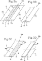
- Figures 3A-3D schematically illustrate a sequence of folding a stretch of the continuous web 100a for making a multilayer web 100 of the type illustrated in Figure 3 , used to make a multilayer tube 1 of the type illustrated in Figures 1 and 2 .
- the web 100a of Figures 3A-3D has a longitudinal right-hand strip 103a, a longitudinal middle strip 104a and a longitudinal left-hand strip 102a.
- the folding sequence comprises initially applying adhesive according to a predetermined distribution on the first glue zones 5a ( Figure 3A ) of the longitudinal middle strip 104a.
- the adhesive can be applied on the first glue zones 5a of the longitudinal right-hand strip 103a or on both the strips 103a and 104a.
- the strip 103a is folded about a first fold line P1, parallel to a longitudinal direction of extension of the web 100a to be superposed on the strip 104a to make a first two-layer portion of the multilayer web 100 ( Figure 3B ).
- the adhesive can be applied on the first glue zones 5a of the longitudinal left-hand strip 102a or on both the strips 103a and 102a.
- the strip 102a is folded ( Figure 3D ) about a second fold line P2, parallel to a longitudinal direction of extension of the web 100a to be superposed on the strip 103a (already superposed on the strip 104a) to make a three-layer web 100.
- the adhesive can be applied on the zones 5a of the strips 102a, 103a, 104a before the steps of folding.
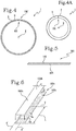
- the multilayer web 100 illustrated in Figure 5 is obtained by at least partly superposing two webs 100b, 100c ( Figure 6 ) in such a way that corresponding longitudinal strips 102b, 103c of the respective webs 100b, 100c (corresponding to the layers 102, 103, of the multilayer web 100) are mutually superposed to form the two-layer thickness of the tube 1 of Figure 4 .
- Figure 4A illustrates a variant of the embodiment of the two-layer web 100 of Figure 4 , where the second, inner layer 3 is thicker than the first, outer layer 2 and is wrapped in such a way that the opposite edges 101 are juxtaposed to form the seam 101', while the first layer 2 is much thinner and wider than the second layer 3 so that when it is wrapped (to form the tube 1), it encloses the second layer 3 and the respective opposite edges partly surmount each other to make an overlap whose thickness is negligible compared to the thickness of the tube 1.
- Figure 6 schematically illustrates the step of superposing the first web 100b on the second web 100c in such a way that the first zones 5a of the second web 100c, previously spread with glue, can adhere to the first zones 5a of the first web 100b (not visible in Figure 6 ).
- Figure 7 illustrates a third embodiment of the tube 1 according to the invention. More specifically, Figure 7 shows a portion of a continuous tube 1 which can subsequently be cut into tubes 1 of predetermined length.
- the tube 1 of Figure 7 is obtained by wrapping a single web 100d ( Figure 8 ) along a helical path around the longitudinal axis X, in such a way as to mutually superpose corresponding longitudinal strips 100d', 100d" of the web 100d of Figure 8 to form the multilayer thickness of the tube 1 of Figure 7 .
- the number of layers of the multilayer thickness of the tube 1 can be increased based on the width of the longitudinal strips 100d', 100d".
- wrapping along a helical path can also be performed on a multilayer web 100 without departing from the inventive concept of this invention,.
- Also part of this invention is a method for making the multilayer tube 1 of the type illustrated in Figure 1 , comprising the following steps:
- the method also comprises a step of perforating the multilayer tube 1 thus obtained, or of perforating the multilayer web 100, in the second zones 5b to make the perforations 6.
- the method preferably also comprises a step of feeding the single web 100a along a feed direction A and the step of superposing is accomplished by folding the web 100a around the first fold line P1 and the second fold line P2 (for example in the manner described above with reference to Figures 3A-3D ) so as to mutually superpose corresponding longitudinal strips 102a, 103a, 104a to form a three-layer thickness of the tube.
- the method comprises a step of feeding two webs 100b, 100c along respective feed directions A', A" and the step of superposing is accomplished by partly superposing the two webs 100b, 100c in such a way as to mutually superpose corresponding longitudinal strips 102b, 103c to form a two-layer thickness.
- the step of applying the adhesive may be carried out before or during the step of superposing, whilst the step of perforating can be carried out preferably after the step of gluing and after the step of superposing.
- the tube 1 obtained is cut into segments of predetermined length L ( Figures 1 , 3D , 6 ).
- Figures 3D and 6 indicate the position of a cutting line T that will result from cutting the continuous tube 1.
- Also part of this invention is a method for making the multilayer tube 1 of the type illustrated in Figure 8 , comprising the following steps:
- the method also comprises a step of perforating the multilayer tube 1 thus obtained, or of perforating the web 100d, in the second zones 5b to make the perforations 6.
- the step of gluing is carried out before the step of wrapping and, preferably, the step of perforating is carried out after the step of gluing and after the step of wrapping.
- step of gluing of the methods of making the tubes 100 just described can preferably be carried out by glue sprayers, not illustrated, which means the step of gluing advantageously comprises a sub-step of adjusting glue emission in such a way that the glue is delivered selectively only on some zones 5a, 5b of the overlapping areas 5 or in such a way as to deliver different amounts of glue on different zones 5a, 5b of the overlapping areas 5.
- the step of gluing is carried out by one or more rollers, not illustrated, whose outside surface is provided with one or more recesses for differentiated or selective application of adhesive on different zones 5a, 5b of the overlapping areas 5.
- the adhesive or glue applied on the zones 5a, 5b may also be activated by microwaves in a step following the step of wrapping or the step of perforating.
- the method according to this invention allows making a continuous multilayer tube 1 which can be cut into segments 1a of predetermined length and combined with a number "n" of segments 1b, 1c of tube having different properties and which can be obtained according to this invention or using other working processes.
- the method can therefore preferably comprise a step of cutting a tube 1 into segments 1a of predetermined size, followed by a step of combining with other tube segments 1b, 1c.
- the step of combining comprises a sub-step of disposing a predetermined number of segments 1a, 1b, 1c in series in a predetermined sequence and a sub-step, preferably simultaneous, of wrapping the segments 1a, 1b, 1c in an outer layer W in order to join them together.
- the step of perforating can be carried out before, simultaneously, or upstream of the step of combining, as will become clearer below, in the description of the machine 100 according to this invention.
- a machine 100 for making a multilayer tube 1, of the kind illustrated in Figure 2 comprising:
- a machine 100 for making a multilayer tube 1, of the kind illustrated in Figure 4 or 4A comprising:
- the two machines 100 just described also advantageously comprise a perforating unit configured to perforate the tube 1 or the multilayer tube 100 in the second, reduced or zero glue zones 5 to make the plurality of perforations 6 according to a predetermined distribution.
- the applicator unit is disposed upstream of the forming unit and the perforating unit is disposed downstream of the wrapping unit.
- a machine 100 for making a multilayer tube 1, of the kind illustrated in Figure 7 comprising:
- the machine 100 just described also advantageously comprises a perforating unit configured to perforate the tube 1 or the multilayer tube 100 in the second, reduced or zero glue zones 5 to make the plurality of perforations 6 according to a predetermined distribution.
- a perforating unit configured to perforate the tube 1 or the multilayer tube 100 in the second, reduced or zero glue zones 5 to make the plurality of perforations 6 according to a predetermined distribution.
- the applicator unit is disposed upstream of the helical wrapping unit and the perforating unit is disposed downstream of the wrapping unit. More specifically, in the three machines 100 just described, the perforating unit is preferably a laser perforating unit.
- the applicator units comprise sprayers which are adjustable in such a way that the glue is delivered selectively only on some zones 5a, 5b of the overlapping areas 5 or in such a way as to deliver different amounts of glue on different zones 5a, 5b of the overlapping areas 5.
- the applicator units may comprise one or more rollers whose outside surface is provided with one or more recesses for differentiated or selective application of glue on different zones 5a, 5b of the overlapping areas 5.
- Figure 9 shows a partial diagram of a machine 100 for making a multilayer tube 1 according to this invention.
- the machine 100 preferably comprises a cutting unit 101 for cutting the tube 1 and configured to make a plurality di cuts T to make the segments 1a.
- the segments 1a may already have been subjected to the perforating operations, at an earlier stage, in the perforating unit, not illustrated, upstream of the cutting unit 101.
- the machine 100 may also preferably comprise a combining unit 102 disposed upstream of the cutting unit 101 and configured to combine further segments 1b, 1c with the segments 1a, disposing them in series in a predetermined sequence and wrapping them in an outer layer W.
- the combining unit 102 just described also advantageously comprises a perforating device 103 configured to make the perforations 6 on the outside surface of the layer W in the second zones 5b of the segments 1a.
- the perforations 6 are made only in the second zones 5b, which are dedicated and predetermined in such a way that perforating them does not produce dirt and adhesive residues, allowing high quality products to be made.
- tubes 1 with a larger number of layers than the three embodiments described herein are also imaginable without departing from the scope of the inventive concept: that is, tubes which can be made by folding a single web 100a or by superposing two or more webs 100b, 100c or by superposing longitudinal strips 100d', 100d" larger in width in such a way that they are superposed two or more times along the helical path or by decreasing the pitch of the helix.
- This invention overcomes the drawbacks of the prior art by providing a multilayer tube 1 of high quality, which can be perforated effectively without producing adhesive residues, and by providing also a machine and a method for making the multilayer tube.
Landscapes
- Making Paper Articles (AREA)
- Extrusion Moulding Of Plastics Or The Like (AREA)
- Laminated Bodies (AREA)
Abstract
Description
- This invention relates to a multilayer tube and to a machine and a method for making it.
- The invention is applicable in particular in the tobacco industry.
- Known in the tobacco industry is the need for tube-shaped elements of paper material, in particular for use as components of "HNB" (heat-not-burn) cigarettes, such as filters and cigarette segments.
- For increased strength, these tube-shaped elements are made with a multilayer structure.
- Generally speaking, the tube-shaped elements are made by superposing and gluing two paper webs in such a way as to obtain, on one or both of the longitudinal edges, suitable joining zones intended to be spliced to each other to form a tube-like configuration.
- Also, to obtain a shape that is as cylindrical as possible, the two webs are offset during superposing and gluing, so that, when the tube is formed, the splices between the corresponding end edges of the two layers are angularly spaced from each other about the axis of the tube itself. Typically, prior art machines that make these multilayer tubes are equipped with adhesive/glue dispensers used to spread a layer of glue on the zones where the two webs making up the tube overlap after being wrapped on themselves to make the multilayer tube.
- The Applicant has found that gluing operations need to be controlled in order to be able to carry out further processes on the tube.
- Indeed, the Applicant has observed that, in many cases, applying an adhesive material between the layers making up the tube prevents subsequent processing from being carried out effectively on the areas where the glue is. The presence of a non-compact material such as the adhesive may have a negative effect on certain processes, preventing good quality products from being made.
- The Applicant has found that glue residues often cause large quantities of dirt to accumulate during subsequent processing on the multilayer tube.
- In this context, the technical purpose which forms the basis of this invention is to propose a multilayer tube, as well as a machine and a method for making it, to overcome one or more of the above mentioned drawbacks of the prior art.
- In particular, this invention has for an aim to provide a high-quality multilayer tube that is versatile in use.
- A further aim is to provide a machine for making a multilayer tube which allows optimizing gluing operations in order to obtain tubes which are very versatile in use and which, in particular, can be effectively subjected to further processing.
- A yet further aim is to provide a method for making a multilayer tube to allow improving the flexibility of use of the tube and the efficiency of the production process.
- The technical purpose indicated and the aims specified are substantially achieved by a multilayer tube, a machine and method for making it comprising the technical features described in one or more of the appended claims.
- More specifically, this invention provides a multilayer tube having an internally hollow, cylindrical shape extending round a longitudinal axis and having, in cross section transverse to the longitudinal axis, a multilayer thickness defined by at least two layers superposed at respective overlapping areas.
- The overlapping areas are glued to each other at first glue zones and, advantageously, have second, reduced or zero glue zones configured and/or intended to receive a plurality of perforations.
- Thanks to this invention, therefore, by reducing or totally eliminating the adhesive in some zones (the second, reduced or zero glue zones), it is possible to drastically reduce the accumulation of dirt and glue residues resulting from subsequent processes, such as the making of perforations, for example.
- In effect, these multilayer tubes are often subjected to a perforation process whereby small perforations are made on the surface of the multilayer tube for different purposes, depending on the kind of smoking article to be made. The Applicant has noticed that when the multilayer tubes are perforated - for example by laser perforation - the combustion of the paper in contact with the glue results in the accumulation of a considerable amount of dirt. The dirt and glue residues can mix with the tobacco, resulting in poor quality cigarettes and having a negative influence on the user's smoking experience.
- Advantageously, this invention allows overcoming this problem by providing a multilayer tube having suitable second zones with a reduced amount of glue or no glue at all, where the perforations can be made in a controlled manner in such a way as not to produce dirt and residues.
- The machine for making the multilayer tube of this invention thus advantageously allows making perforations on the tube effectively, without producing dirt and adhesive residues in the perforation areas and resulting in the production of a high-quality multilayer tube.
- Furthermore, the method for making the multilayer tube of this invention thus advantageously allows perforating the tube effectively while preventing dirt and adhesive residues from being produced in the perforation areas, thus allowing a high-quality multilayer tube to be made.
- All the accompanying claims, which are incorporated herein by reference, correspond to different embodiments of the invention.
- Further features and advantages of this invention are more apparent in the non-limiting description of a preferred but non-exclusive embodiment of a multilayer tube, as illustrated in the accompanying drawings, in which:
-
Figure 1 is a schematic side view of a multilayer tube according to this invention; -
Figure 2 is a schematic transverse cross section of a first embodiment of a multilayer tube according to this invention; -
Figure 3 is a schematic transverse cross section of a multilayer web used to make the multilayer tube ofFigure 2 ; -
Figures 3A-3D illustrate a sequence of working steps for making the multilayer tube ofFigure 3 ; -
Figure 4 is a schematic transverse cross section of a second embodiment of a multilayer tube according to this invention; -
Figure 4A shows a variant of the embodiment ofFigure 4 ; -
Figure 5 is a schematic transverse cross section of a multilayer web used to make the multilayer tube ofFigure 4 ; -
Figure 6 illustrates a working step for making the multilayer tube ofFigure 5 ; -
Figure 7 is a schematic perspective view of a third embodiment of a multilayer tube according to this invention; -
Figure 8 is a schematic plan view of a stretch of web used to make the multilayer tube ofFigure 7 ; and -
Figure 9 is a partial diagram of a machine for making a multilayer tube according to this invention. - With reference to the accompanying drawings, the
numeral 1 denotes a multilayer tube in its entirety. - The
tube 1 according to this invention has an internally hollow, cylindrical shape extending round a longitudinal axis X. - The
tube 1 has, in cross section transverse to the longitudinal axis X, a multilayer thickness defined by at least twosuperposed layers - More specifically, in the two embodiments illustrated in
Figures 2 and4 , thetube 1 has a three-layer thickness, with anouter layer 2, amiddle layer 3 and aninner layer 4. Thesuperposed layers - Preferably, the
layers - The
layers areas 5 which are inclined to each other atfirst glue zones 5a. The overlappingareas 5 also have reduced or zeroglue zones 5b. - It should be noted that the expression "
first glue zones 5a" is used to mean "normal" gluing zones where the adhesive is applied in a predetermined quantity to all thelayers glue zones 5b" is used to indicate zones where the thickness or surface density of the adhesive applied is less than in the first glue zones.5a. In other words, in thezones 5b, the adhesive may be applied in reduced quantities (for example, glue dots) compared to thefirst glue zones 5a or not applied at all. The accompanying drawings illustrate example embodiments where thesecond zones 5b are zero glue zones, hence without any adhesive. - In particular, according to this invention, the
second zones 5b are configured and/or intended to receive a plurality ofperforations 6. - The expression "configured and/or intended to receive" as used herein means that the
second zones 5b are of a size such as to be able to receive a certain number ofperforations 6. - In a preferred embodiment of this invention, therefore, the
second zones 5b of thetube 1, as illustrated inFigure 1 , have a plurality ofperforations 6 disposed according to a predetermined distribution. - More specifically, in the example embodiment of
Figure 1 , theperforations 6 are circular in shape and are made in a row along at least one stretch of the circumference of thetube 1. - Advantageously, the perforation is thus made in the
second zones 5b where there is no adhesive or where the quantity of adhesive is reduced compared to thefirst zones 5a, thereby considerably reducing, or even totally eliminating, the production of dirt or adhesive residues resulting from perforation. - Preferably, the first and
second zones Figures 3A and 3C , thesecond zones 5b may define rectangles repeated at predetermined intervals and bordered on all sides by thefirst zones 5a. - With reference to the first and second embodiments of the
multilayer tube 1, illustrated inFigures 2 and4 , respectively, themultilayer tube 1 according to this invention can be obtained preferably by wrapping amultilayer web 100, comprising at least twolayers layers tube 1, around the longitudinal axis X, until mutually juxtaposing and joining oppositelateral edges 101 of themultilayer web 100 to form a longitudinal seam 101'. - In particular, the
multilayer web 100 illustrated inFigure 3 , relating to the first embodiment ofFigure 2 , is obtained by folding asingle web 100a around at least one fold line P1, P2, preferably parallel to the longitudinal axis X, until correspondinglongitudinal strips layers tube 1. -
Figures 3A-3D schematically illustrate a sequence of folding a stretch of thecontinuous web 100a for making amultilayer web 100 of the type illustrated inFigure 3 , used to make amultilayer tube 1 of the type illustrated inFigures 1 and 2 . - More specifically, the
web 100a ofFigures 3A-3D has a longitudinal right-hand strip 103a, alongitudinal middle strip 104a and a longitudinal left-hand strip 102a. - The folding sequence comprises initially applying adhesive according to a predetermined distribution on the
first glue zones 5a (Figure 3A ) of thelongitudinal middle strip 104a. Alternatively, in a possible operating mode not illustrated, the adhesive can be applied on thefirst glue zones 5a of the longitudinal right-hand strip 103a or on both thestrips strip 103a is folded about a first fold line P1, parallel to a longitudinal direction of extension of theweb 100a to be superposed on thestrip 104a to make a first two-layer portion of the multilayer web 100 (Figure 3B ). - At this point, more adhesive is applied according to a predetermined distribution on the
first glue zones 5a (Figure 3C ) of the longitudinal right-hand strip 103a, which is already superposed on thestrip 104a. Alternatively, in this case, too, in a possible operating mode not illustrated, the adhesive can be applied on thefirst glue zones 5a of the longitudinal left-hand strip 102a or on both thestrips - Next, the
strip 102a is folded (Figure 3D ) about a second fold line P2, parallel to a longitudinal direction of extension of theweb 100a to be superposed on thestrip 103a (already superposed on thestrip 104a) to make a three-layer web 100. - It should be noted that the adhesive can be applied on the
zones 5a of thestrips - In a possible embodiment not illustrated in the accompanying drawings, there may be at least one oblique fold line.
- Preferably, the
multilayer web 100 illustrated inFigure 5 , specifically a two-layer web 100 relating to the second embodiment ofFigure 4 , is obtained by at least partly superposing twowebs Figure 6 ) in such a way that correspondinglongitudinal strips respective webs layers tube 1 ofFigure 4 . -
Figure 4A illustrates a variant of the embodiment of the two-layer web 100 ofFigure 4 , where the second,inner layer 3 is thicker than the first,outer layer 2 and is wrapped in such a way that theopposite edges 101 are juxtaposed to form the seam 101', while thefirst layer 2 is much thinner and wider than thesecond layer 3 so that when it is wrapped (to form the tube 1), it encloses thesecond layer 3 and the respective opposite edges partly surmount each other to make an overlap whose thickness is negligible compared to the thickness of thetube 1. -
Figure 6 schematically illustrates the step of superposing thefirst web 100b on thesecond web 100c in such a way that thefirst zones 5a of thesecond web 100c, previously spread with glue, can adhere to thefirst zones 5a of thefirst web 100b (not visible inFigure 6 ). -
Figure 7 illustrates a third embodiment of thetube 1 according to the invention. More specifically,Figure 7 shows a portion of acontinuous tube 1 which can subsequently be cut intotubes 1 of predetermined length. - Preferably, the
tube 1 ofFigure 7 is obtained by wrapping asingle web 100d (Figure 8 ) along a helical path around the longitudinal axis X, in such a way as to mutually superpose correspondinglongitudinal strips 100d', 100d" of theweb 100d ofFigure 8 to form the multilayer thickness of thetube 1 ofFigure 7 . - It should be noted that the number of layers of the multilayer thickness of the
tube 1 can be increased based on the width of thelongitudinal strips 100d', 100d". - It should be noted that wrapping along a helical path can also be performed on a
multilayer web 100 without departing from the inventive concept of this invention,. - Also part of this invention is a method for making the
multilayer tube 1 of the type illustrated inFigure 1 , comprising the following steps: - superposing at least two
layers Figure 2 and two layers in the case ofFigures 4 and 4A ) at respective overlappingareas 5 to form themultilayer web 100; - applying a predetermined, "normal" quantity of adhesive on the
first zones 5a of the overlappingareas 5 and applying a reduced quantity of adhesive on thesecond zones 5b or no adhesive at all on thesecond zones 5b; - wrapping the multilayer web 100 (
Figures 3 and5 ) around the longitudinal axis X and stably joining together the opposite side edges 101 of themultilayer web 100 to form the longitudinal seam 101' in such a way that themultilayer tube 1 has, in cross section transverse to the longitudinal axis X, a multilayer thickness defined by the at least two superposed layers. - Preferably, the method also comprises a step of perforating the
multilayer tube 1 thus obtained, or of perforating themultilayer web 100, in thesecond zones 5b to make theperforations 6. - With reference to the first embodiment of
Figures 2-3D , the method preferably also comprises a step of feeding thesingle web 100a along a feed direction A and the step of superposing is accomplished by folding theweb 100a around the first fold line P1 and the second fold line P2 (for example in the manner described above with reference toFigures 3A-3D ) so as to mutually superpose correspondinglongitudinal strips - With reference to the second embodiment of
Figures 4-6 , on the other hand, the method comprises a step of feeding twowebs webs longitudinal strips - Also, preferably, the step of applying the adhesive may be carried out before or during the step of superposing, whilst the step of perforating can be carried out preferably after the step of gluing and after the step of superposing.
- Also, preferably, after the step of wrapping or after the step of perforating, the
tube 1 obtained is cut into segments of predetermined length L (Figures 1 ,3D ,6 ). -
Figures 3D and6 indicate the position of a cutting line T that will result from cutting thecontinuous tube 1. - Also part of this invention is a method for making the
multilayer tube 1 of the type illustrated inFigure 8 , comprising the following steps: - feeding the
continuous web 100d (Figure 8 ) along a feed direction A'"; - wrapping the
web 100d along a helical path around a longitudinal axis X, in such a way as to mutually superpose correspondinglongitudinal strips 100d', 100d" of theweb 100d so as to superpose at least twolayers areas 5, the step of superposing forming a multilayer thickness of thetube 1; and - applying a predetermined, "normal" quantity of adhesive on the
first zones 5a of the overlappingareas 5 and applying a reduced quantity of adhesive on thesecond zones 5b or no adhesive at all on thesecond zones 5b; - Preferably, the method also comprises a step of perforating the
multilayer tube 1 thus obtained, or of perforating theweb 100d, in thesecond zones 5b to make theperforations 6. - Preferably, the step of gluing is carried out before the step of wrapping and, preferably, the step of perforating is carried out after the step of gluing and after the step of wrapping.
- The step of gluing of the methods of making the
tubes 100 just described, which refer to the embodiments illustrated in the drawings, can preferably be carried out by glue sprayers, not illustrated, which means the step of gluing advantageously comprises a sub-step of adjusting glue emission in such a way that the glue is delivered selectively only on somezones areas 5 or in such a way as to deliver different amounts of glue ondifferent zones areas 5. - Also, alternatively, the step of gluing is carried out by one or more rollers, not illustrated, whose outside surface is provided with one or more recesses for differentiated or selective application of adhesive on
different zones areas 5. - It should be noted that the adhesive or glue applied on the
zones - The method according to this invention allows making a
continuous multilayer tube 1 which can be cut intosegments 1a of predetermined length and combined with a number "n" ofsegments - With reference to
Figure 9 , the method can therefore preferably comprise a step of cutting atube 1 intosegments 1a of predetermined size, followed by a step of combining withother tube segments - More specifically, the step of combining comprises a sub-step of disposing a predetermined number of
segments segments - Advantageously, therefore, in a possible embodiment of the method, the step of perforating can be carried out before, simultaneously, or upstream of the step of combining, as will become clearer below, in the description of the
machine 100 according to this invention. - Also part of the invention is a
machine 100 for making amultilayer tube 1, of the kind illustrated inFigure 2 , comprising: - feed means for feeding a
continuous web 100a; - a forming unit for forming the multilayer web 100 (
Figure 3 ) comprising folding means configured to fold thecontinuous web 100a around the first fold line P1 and the second fold line P2; - a wrapping unit for longitudinally wrapping the
multilayer web 100 around the longitudinal axis X until juxtaposing and joining together the opposite side edges 101 of themultilayer web 100; and - a glue applicator unit configured to apply glue on
different zones areas 5 in a differentiated or selective manner. - Also part of the invention is a
machine 100 for making amultilayer tube 1, of the kind illustrated inFigure 4 or 4A , comprising: - feed means for feeding two
continuous webs - a forming unit for forming a multilayer web 100 (
Figure 5 ) comprising superposing means configured to at least partly superpose the twocontinuous webs - a wrapping unit for longitudinally wrapping the
multilayer web 100 around the longitudinal axis X until juxtaposing and joining together the opposite side edges 101 of themultilayer web 100; and - a glue applicator unit configured to apply glue on
different zones areas 5 in a differentiated or selective manner. - Preferably, the two
machines 100 just described also advantageously comprise a perforating unit configured to perforate thetube 1 or themultilayer tube 100 in the second, reduced or zeroglue zones 5 to make the plurality ofperforations 6 according to a predetermined distribution. Preferably, also, in the twomachines 100 mentioned above, the applicator unit is disposed upstream of the forming unit and the perforating unit is disposed downstream of the wrapping unit. - Also part of the invention is a
machine 100 for making amultilayer tube 1, of the kind illustrated inFigure 7 , comprising: - feed means for feeding a
continuous web 100d (Figure 8 ); - a helical wrapping unit for helically wrapping the
web 100d along a helical path around the longitudinal axis X, where the wrapping unit comprises superposing means configured to mutually superpose the correspondinglongitudinal strips 100d', 100d" of theweb 100d; and - a glue applicator unit configured to apply glue on
different zones areas 5 in a differentiated or selective manner. - Preferably, the
machine 100 just described also advantageously comprises a perforating unit configured to perforate thetube 1 or themultilayer tube 100 in the second, reduced or zeroglue zones 5 to make the plurality ofperforations 6 according to a predetermined distribution. - Preferably, the applicator unit is disposed upstream of the helical wrapping unit and the perforating unit is disposed downstream of the wrapping unit. More specifically, in the three
machines 100 just described, the perforating unit is preferably a laser perforating unit. - Preferably, also, the applicator units comprise sprayers which are adjustable in such a way that the glue is delivered selectively only on some
zones areas 5 or in such a way as to deliver different amounts of glue ondifferent zones areas 5. - Alternatively, the applicator units may comprise one or more rollers whose outside surface is provided with one or more recesses for differentiated or selective application of glue on
different zones areas 5. -
Figure 9 shows a partial diagram of amachine 100 for making amultilayer tube 1 according to this invention. - More specifically, the
machine 100 preferably comprises acutting unit 101 for cutting thetube 1 and configured to make a plurality di cuts T to make thesegments 1a. - In a possible embodiment of the invention, the
segments 1a may already have been subjected to the perforating operations, at an earlier stage, in the perforating unit, not illustrated, upstream of thecutting unit 101. Alternatively, themachine 100 may also preferably comprise a combiningunit 102 disposed upstream of thecutting unit 101 and configured to combinefurther segments segments 1a, disposing them in series in a predetermined sequence and wrapping them in an outer layer W. - The combining
unit 102 just described also advantageously comprises a perforatingdevice 103 configured to make theperforations 6 on the outside surface of the layer W in thesecond zones 5b of thesegments 1a. - That way, the
perforations 6 are made only in thesecond zones 5b, which are dedicated and predetermined in such a way that perforating them does not produce dirt and adhesive residues, allowing high quality products to be made. - Also imaginable without departing from the scope of the inventive concept are
tubes 1 with a larger number of layers than the three embodiments described herein: that is, tubes which can be made by folding asingle web 100a or by superposing two ormore webs longitudinal strips 100d', 100d" larger in width in such a way that they are superposed two or more times along the helical path or by decreasing the pitch of the helix. - This invention overcomes the drawbacks of the prior art by providing a
multilayer tube 1 of high quality, which can be perforated effectively without producing adhesive residues, and by providing also a machine and a method for making the multilayer tube.
Claims (28)
- A multilayer tube (1) having an internally hollow, cylindrical shape extending round a longitudinal axis (X) and having, in cross section transverse to the longitudinal axis (X), a multilayer thickness defined by at least two layers (2, 3, 4) superposed at respective overlapping areas (5), the overlapping areas (5) being glued to each other at first glue zones (5a) and having second, reduced or zero glue zones (5b) configured and/or intended to receive a plurality of perforations (6).
- The multilayer tube (1) according to claim 1, wherein the second, reduced or zero glue zones (5b) are provided with a plurality of perforations (6) arranged according to a predetermined pattern.
- The multilayer tube (1) according to claim 2, wherein the plurality of perforations (6) is made only at the second, reduced or zero glue zones (5b).
- The multilayer tube (1) according to claim 1, wherein the multilayer tube (1) is obtained by wrapping a multilayer web (100) around the longitudinal axis (X) until juxtaposing and joining together the opposite side edges (101) of the multilayer web (100) to form a longitudinal seam (101'), wherein the multilayer web (100) is obtained by at least partly superposing at least two webs (100b, 100c) in such a way as to mutually superpose corresponding longitudinal strips (102b, 103c) of respective webs (100b, 100c) to form the multilayer thickness.
- The multilayer tube (1) according to claim 1, wherein the multilayer tube (1) is obtained by wrapping a multilayer web (100) around the longitudinal axis (X) until juxtaposing and joining together the opposite side edges (101) of the multilayer web (100) to form a longitudinal seam (101'), wherein the multilayer web (100) is obtained by folding a single web (100a) around at least one fold line (P1, P2), preferably parallel to the longitudinal axis (X), in such a way as to mutually superpose corresponding longitudinal strips (102a, 103a, 104a) of the web (100a) to form the multilayer thickness.
- The multilayer tube (1) according to claim 1, wherein the multilayer tube (1) is obtained by wrapping a single web (100d) along a helical path around the longitudinal axis (X), in such a way as to mutually superpose corresponding longitudinal strips (100d', 100d") of the web (100d) to form the multilayer thickness.
- The multilayer tube (1) according to one or more of the preceding claims, wherein the first and second zones (5a, 5b) are arranged according to a predetermined, recurrent and/or structured pattern.
- A method for making a multilayer tube (1) having an internally hollow, cylindrical shape extending round a longitudinal axis (X), comprising the following steps:- superposing at least two layers (2, 3, 4) at respective overlapping areas (5) to form a multilayer web (100),- gluing the overlapping areas (5) at first glue zones (5a) of the overlapping areas (5), the step of gluing being also accomplished by applying a reduced amount of glue, or no glue at all, on second zones (5b) of the overlapping areas (5), the second zones (5b) being configured and/or intended to receive a plurality of perforations (6),- wrapping the multilayer web (100) around a longitudinal axis (X) and stably joining together opposite side edges (101) of the multilayer web (100) to form a longitudinal seam (101') in such a way that the multilayer tube (1) has, in cross section transverse to the longitudinal axis (X), a multilayer thickness defined by the at least two superposed layers (2, 3, 4).
- The method according to claim 8, comprising a step of perforating the multilayer tube (1) or the multilayer web (100) at the second, reduced or no glue zones (5b) to obtain a plurality of perforations (6) arranged according to a predetermined pattern.
- The method according to claim 9, wherein the step of perforating is carried out after the step of gluing and after the step of superposing.
- The method according to one or more of claims 8-10, comprising a step of feeding at least two webs (100b, 100c) along respective feed directions (A', A") and wherein the step of superposing is accomplished by at least partly superposing the at least two webs (100b, 100c) in such a way as to mutually superpose corresponding longitudinal strips (102b, 103c) of the respective webs (100b, 100c) to form the multilayer thickness.
- The method according to one or more of claims 8-10, comprising a step of feeding a single web (100a) along a feed direction (A) and wherein the step of superposing is accomplished by folding the single web (100a) around at least one fold line (P1, P2), preferably parallel to the longitudinal axis (X), in such a way as to mutually superpose corresponding longitudinal strips (102a, 103a, 104a) of the single web (100a) to form the multilayer thickness.
- The method according to any one of claims 8-12, wherein the step of gluing is carried out before or during the step of superposing.
- A method for making a multilayer tube (1) having an internally hollow, cylindrical shape extending round a longitudinal axis (X), comprising the following steps:- feeding a web (100d) along a feed direction (A"');- wrapping the web (100d) along a helical path around a longitudinal axis (X), in such a way as to mutually superpose corresponding longitudinal strips (100d', 100d") of the web (100d) so as to superpose at least two layers (2, 3, 4) at respective overlapping areas (5), the step of superposing forming a multilayer thickness of the multilayer tube (1),- gluing the overlapping areas (5) at first glue zones (5a) of the overlapping areas (5), the step of gluing being also accomplished by applying a reduced amount of glue, or no glue at all, on second zones (5b) of the overlapping areas (5), the second zones (5b) being configured and/or intended to receive a plurality of perforations (6).
- The method according to claim 14, comprising a step of perforating the multilayer tube (1) or the web (100d) at the second, reduced or no glue zones (5b) to obtain a plurality of perforations (6) arranged according to a predetermined pattern.
- The method according to claim 15, wherein the step of perforating is carried out after the step of gluing and after the step of wrapping.
- The method according to claim 15 or 16, wherein the step of gluing is carried out before the step of wrapping.
- The method according to any one of claims 8-17, wherein the step of gluing is carried out by glue sprayers, the step of gluing comprising a sub-step of adjusting glue emission in such a way that the glue is delivered selectively only on some zones (5a, 5b) of the overlapping areas (5) or in such a way as to deliver different amounts of glue on different zones (5a, 5b) of the overlapping areas (5).
- The method according to any one of claims 8-17, wherein the step of gluing is carried out by one or more rollers whose outside surface is provided with one or more recesses for differentiated or selective application of glue on different zones of the overlapping areas (5).
- A machine for making a multilayer tube (1), comprising:- feed means for feeding at least two continuous webs (100b, 100c);- a forming unit for forming a multilayer web (100) comprising superposing means configured to at least partly superpose the at least two continuous webs (100b, 100c), to mutually superpose corresponding longitudinal strips (102b, 103c) of the webs (100b, 100c) to form a multilayer thickness of the multilayer tube (1), the longitudinal strips (102b, 103c) being superposed at respective overlapping areas (5) and forming at least two layers (2, 3, 4) of the multilayer thickness;- a wrapping unit for longitudinally wrapping the multilayer web (100) around a longitudinal axis (X) until juxtaposing and joining together the opposite side edges (101) of the multilayer web (100) to form a longitudinal seam (101');- a glue applicator unit configured to apply glue on different zones (5a, 5b) of the overlapping areas (5) in a differentiated or selective manner, the overlapping areas (5) having first glue zones (5a) and second, reduced or no glue zones (5b), the second zones (5b) being configured and/or intended to receive a plurality of perforations (6).
- A machine for making a multilayer tube (1), comprising:- feed means for feeding a continuous web (100a);- a forming unit for forming a multilayer web (100) comprising folding means configured to fold the continuous web (100a) around at least one fold line (P1, P2), preferably parallel the longitudinal axis (X), to mutually superpose corresponding longitudinal strips (102a, 103a, 104a) of the web (100a) to form a multilayer thickness of the multilayer tube (1), the longitudinal strips (102a, 103a, 104a) being superposed at respective overlapping areas (5) and forming at least two layers (2, 3, 4) of the multilayer thickness;- a wrapping unit for longitudinally wrapping the multilayer web (100) around a longitudinal axis (X) until juxtaposing and joining together the opposite side edges (101) of the multilayer web (100) to form a longitudinal seam (101');- a glue applicator unit configured to apply glue on different zones (5a, 5b) of the overlapping areas (5) in a differentiated or selective manner, the overlapping areas (5) having first glue zones (5a) and second, reduced or no glue zones (5b), the second zones (5b) being configured and/or intended to receive a plurality of perforations (6).
- The machine according to claim 20 or 21, comprising a perforating unit configured to perforate the multilayer tube (1) or the multilayer web (100) at the second, reduced or no glue zones (5b) to obtain a plurality of perforations (6) arranged according to a predetermined pattern.
- The machine according to claim 22, wherein the applicator unit is located upstream of the forming unit and wherein the perforating unit is located downstream of the wrapping unit.
- A machine for making a multilayer tube, comprising:- feed means for feeding a continuous web (100d);- a wrapping unit for helically wrapping the continuous web (100d) along a helical path around a longitudinal axis (X), the wrapping unit comprising superposing means configured to mutually superpose corresponding longitudinal strips (100d', 100d") of the continuous web (100d) in such a way as to superpose at least two layers (2, 3, 4) at respective overlapping areas (5), the superposed layers forming a multilayer thickness of the multilayer tube (100),- a glue applicator unit configured to apply glue on different zones (5a, 5b) of the overlapping areas (5) in a differentiated or selective manner, the overlapping areas (5) having first glue zones (5a) and second, reduced or no glue zones (5b), the second zones (5b) being configured and/or intended to receive a plurality of perforations (6).
- The machine according to claim 24, comprising a perforating unit configured to perforate the multilayer tube (1) or the multilayer web (100) at the second, reduced or no glue zones (5b) to obtain a plurality of perforations (6) arranged according to a predetermined pattern.
- The machine according to claim 25, wherein the applicator unit is located upstream of the helical wrapping unit and wherein the perforating unit is located downstream of the wrapping unit.
- The machine according to any one of claims 20-26, wherein the applicator unit comprises sprayers which are adjustable in such a way that the glue is delivered selectively only on some zones (5a, 5b) of the overlapping areas (5) or in such a way as to deliver different amounts of glue on different zones (5a, 5b) of the overlapping areas (5).
- The machine according to any one of claims 20-26, wherein the applicator unit comprises one or more rollers whose outside surface is provided with one or more recesses for differentiated or selective application of glue on different zones (5a, 5b) of the overlapping areas (5).
Applications Claiming Priority (1)
| Application Number | Priority Date | Filing Date | Title |
|---|---|---|---|
| IT102018000009358A IT201800009358A1 (en) | 2018-10-11 | 2018-10-11 | Multilayer tubular and relative machine and method for its realization |
Publications (3)
| Publication Number | Publication Date |
|---|---|
| EP3636082A2 true EP3636082A2 (en) | 2020-04-15 |
| EP3636082A3 EP3636082A3 (en) | 2020-09-02 |
| EP3636082B1 EP3636082B1 (en) | 2025-02-12 |
Family
ID=64902275
Family Applications (1)
| Application Number | Title | Priority Date | Filing Date |
|---|---|---|---|
| EP19201826.5A Active EP3636082B1 (en) | 2018-10-11 | 2019-10-08 | Multilayer tube and related machine and method for making it |
Country Status (3)
| Country | Link |
|---|---|
| EP (1) | EP3636082B1 (en) |
| IT (1) | IT201800009358A1 (en) |
| PL (1) | PL3636082T3 (en) |
Cited By (2)
| Publication number | Priority date | Publication date | Assignee | Title |
|---|---|---|---|---|
| EP4245156A1 (en) * | 2022-03-18 | 2023-09-20 | JT International SA | Cooling segment for an aerosol generating article |
| EP4501140A4 (en) * | 2022-03-31 | 2026-04-08 | Japan Tobacco Inc | TUBE BODY |
Family Cites Families (12)
| Publication number | Priority date | Publication date | Assignee | Title |
|---|---|---|---|---|
| US1996066A (en) * | 1930-12-05 | 1935-04-02 | Soda Straw Mfg Corp | Drinking tube and method of manufacturing same |
| BE788318A (en) * | 1972-09-01 | 1973-01-02 | British American Tobacco Co | FILTER FOR CIGARETTE, PROCESS FOR MANUFACTURING THIS FILTER AND DEVICE FOR IMPLEMENTING THIS PROCESS. |
| LU72117A1 (en) * | 1975-03-24 | 1975-08-20 | ||
| LU72479A1 (en) * | 1975-05-15 | 1975-08-28 | ||
| DE2734643A1 (en) * | 1976-10-13 | 1978-04-20 | Hauni Werke Koerber & Co Kg | METHOD AND MACHINE FOR MANUFACTURING ROD-SHAPED SMOKING ARTICLES WITH A SHELL MATERIAL HAVING A DEFINED AIR PERMEABILITY |
| GB2055669B (en) * | 1979-08-02 | 1983-04-07 | Molins Ltd | Perforation of web material |
| GB2159386B (en) * | 1984-05-25 | 1988-05-11 | Molins Plc | Cigarette manufacture |
| GB2171168B (en) * | 1985-02-16 | 1989-02-22 | Molins Plc | Tube manufacture |
| DE4106127C2 (en) * | 1991-02-27 | 2003-05-28 | Hauni Werke Koerber & Co Kg | Method and device for perforating cigarette wrapping material |
| IT1299841B1 (en) * | 1998-02-13 | 2000-04-04 | Gd Spa | METHOD AND FEEDING OF WRAPPING MATERIAL IN SMOKE PACKAGING MACHINES. |
| KR102022302B1 (en) * | 2016-10-25 | 2019-11-04 | 태영산업 주식회사 | apparatus for manufacturing cigarette filter |
| DE102016124051A1 (en) * | 2016-12-12 | 2018-06-14 | Hauni Maschinenbau Gmbh | Doppellagiges tube of the tobacco processing industry and method for producing such a tube |
-
2018
- 2018-10-11 IT IT102018000009358A patent/IT201800009358A1/en unknown
-
2019
- 2019-10-08 PL PL19201826.5T patent/PL3636082T3/en unknown
- 2019-10-08 EP EP19201826.5A patent/EP3636082B1/en active Active
Cited By (2)
| Publication number | Priority date | Publication date | Assignee | Title |
|---|---|---|---|---|
| EP4245156A1 (en) * | 2022-03-18 | 2023-09-20 | JT International SA | Cooling segment for an aerosol generating article |
| EP4501140A4 (en) * | 2022-03-31 | 2026-04-08 | Japan Tobacco Inc | TUBE BODY |
Also Published As
| Publication number | Publication date |
|---|---|
| EP3636082A3 (en) | 2020-09-02 |
| IT201800009358A1 (en) | 2020-04-11 |
| EP3636082B1 (en) | 2025-02-12 |
| PL3636082T3 (en) | 2025-05-19 |
Similar Documents
| Publication | Publication Date | Title |
|---|---|---|
| EP3332655B1 (en) | Double layer tube for the tobacco processing industry and method for producing such a tube | |
| EP3033952B1 (en) | Double layer tube for the tobacco processing industry and device and method for producing such a tube | |
| US20130199551A1 (en) | Smoking Article and Method of Manufacturing a Smoking Article | |
| EP3357354A1 (en) | Strand forming device and method of producing a strand in the tobacco-processing industry | |
| EP3636082B1 (en) | Multilayer tube and related machine and method for making it | |
| JP7118897B2 (en) | Method and machine for forming pieces of multi-layered cylindrical tubular rods used to form substantially cylindrical smoker articles, and pieces formed by the method and machine | |
| EP3415131B1 (en) | An apparatus and method for producing an elastic composite tape with intermittent elastic sections | |
| EP3641572A1 (en) | Method for producing smoking article products | |
| US20170347700A1 (en) | Smoking article assembly machine and method of making a smoking article | |
| EP3784066B1 (en) | Multilayer tube of the tobacco industry and method for making the multilayer tube | |
| JP7080830B2 (en) | Processes and equipment for making semi-finished goods chipping paper blanks | |
| EP2999360B1 (en) | Apparatus for making smokers' articles | |
| EP0162704B1 (en) | Manufacture of an expanded web of sheet material | |
| EP2999362B1 (en) | Apparatus for making smokers' articles | |
| EP4340645B1 (en) | Machine and method for making tubular segments, in particular of the tobacco industry or the straw industry | |
| CN115302107A (en) | Device and method for producing perforated sections for the tobacco industry | |
| DE102006021309A1 (en) | Glue jet assembly, for the paper tube overlap around a cigarette tobacco stick, has structured openings giving two tracks to reduce moisture applied to the paper | |
| WO2025088465A1 (en) | Machine and method for making tubular articles and tubular article | |
| CA1274143A (en) | Manufacture of an expanded web of sheet material | |
| GB2329319A (en) | Suction band for a cigarette making machine. | |
| JPH01296966A (en) | Production of composite filter plug for tobacco and apparatus therefor |
Legal Events
| Date | Code | Title | Description |
|---|---|---|---|
| PUAI | Public reference made under article 153(3) epc to a published international application that has entered the european phase |
Free format text: ORIGINAL CODE: 0009012 |
|
| STAA | Information on the status of an ep patent application or granted ep patent |
Free format text: STATUS: THE APPLICATION HAS BEEN PUBLISHED |
|
| AK | Designated contracting states |
Kind code of ref document: A2 Designated state(s): AL AT BE BG CH CY CZ DE DK EE ES FI FR GB GR HR HU IE IS IT LI LT LU LV MC MK MT NL NO PL PT RO RS SE SI SK SM TR |
|
| AX | Request for extension of the european patent |
Extension state: BA ME |
|
| PUAL | Search report despatched |
Free format text: ORIGINAL CODE: 0009013 |
|
| AK | Designated contracting states |
Kind code of ref document: A3 Designated state(s): AL AT BE BG CH CY CZ DE DK EE ES FI FR GB GR HR HU IE IS IT LI LT LU LV MC MK MT NL NO PL PT RO RS SE SI SK SM TR |
|
| AX | Request for extension of the european patent |
Extension state: BA ME |
|
| RIC1 | Information provided on ipc code assigned before grant |
Ipc: B31C 3/04 20060101ALI20200727BHEP Ipc: A24C 5/46 20060101AFI20200727BHEP Ipc: B31C 5/00 20060101ALI20200727BHEP |
|
| STAA | Information on the status of an ep patent application or granted ep patent |
Free format text: STATUS: REQUEST FOR EXAMINATION WAS MADE |
|
| 17P | Request for examination filed |
Effective date: 20210301 |
|
| RBV | Designated contracting states (corrected) |
Designated state(s): AL AT BE BG CH CY CZ DE DK EE ES FI FR GB GR HR HU IE IS IT LI LT LU LV MC MK MT NL NO PL PT RO RS SE SI SK SM TR |
|
| STAA | Information on the status of an ep patent application or granted ep patent |
Free format text: STATUS: EXAMINATION IS IN PROGRESS |
|
| 17Q | First examination report despatched |
Effective date: 20210716 |
|
| P01 | Opt-out of the competence of the unified patent court (upc) registered |
Effective date: 20230528 |
|
| GRAP | Despatch of communication of intention to grant a patent |
Free format text: ORIGINAL CODE: EPIDOSNIGR1 |
|
| STAA | Information on the status of an ep patent application or granted ep patent |
Free format text: STATUS: GRANT OF PATENT IS INTENDED |
|
| RIC1 | Information provided on ipc code assigned before grant |
Ipc: A24C 5/00 20200101ALN20240806BHEP Ipc: B31C 5/00 20060101ALI20240806BHEP Ipc: B31C 3/04 20060101ALI20240806BHEP Ipc: A24C 5/46 20060101AFI20240806BHEP |
|
| INTG | Intention to grant announced |
Effective date: 20240905 |
|
| GRAS | Grant fee paid |
Free format text: ORIGINAL CODE: EPIDOSNIGR3 |
|
| GRAA | (expected) grant |
Free format text: ORIGINAL CODE: 0009210 |
|
| STAA | Information on the status of an ep patent application or granted ep patent |
Free format text: STATUS: THE PATENT HAS BEEN GRANTED |
|
| AK | Designated contracting states |
Kind code of ref document: B1 Designated state(s): AL AT BE BG CH CY CZ DE DK EE ES FI FR GB GR HR HU IE IS IT LI LT LU LV MC MK MT NL NO PL PT RO RS SE SI SK SM TR |
|
| REG | Reference to a national code |
Ref country code: GB Ref legal event code: FG4D |
|
| REG | Reference to a national code |
Ref country code: CH Ref legal event code: EP |
|
| REG | Reference to a national code |
Ref country code: DE Ref legal event code: R096 Ref document number: 602019065700 Country of ref document: DE |
|
| REG | Reference to a national code |
Ref country code: IE Ref legal event code: FG4D |
|
| REG | Reference to a national code |
Ref country code: NL Ref legal event code: FP |
|
| PG25 | Lapsed in a contracting state [announced via postgrant information from national office to epo] |
Ref country code: RS Free format text: LAPSE BECAUSE OF FAILURE TO SUBMIT A TRANSLATION OF THE DESCRIPTION OR TO PAY THE FEE WITHIN THE PRESCRIBED TIME-LIMIT Effective date: 20250512 |
|
| PG25 | Lapsed in a contracting state [announced via postgrant information from national office to epo] |
Ref country code: FI Free format text: LAPSE BECAUSE OF FAILURE TO SUBMIT A TRANSLATION OF THE DESCRIPTION OR TO PAY THE FEE WITHIN THE PRESCRIBED TIME-LIMIT Effective date: 20250212 |
|
| PG25 | Lapsed in a contracting state [announced via postgrant information from national office to epo] |
Ref country code: ES Free format text: LAPSE BECAUSE OF FAILURE TO SUBMIT A TRANSLATION OF THE DESCRIPTION OR TO PAY THE FEE WITHIN THE PRESCRIBED TIME-LIMIT Effective date: 20250212 |
|
| REG | Reference to a national code |
Ref country code: LT Ref legal event code: MG9D |
|
| PG25 | Lapsed in a contracting state [announced via postgrant information from national office to epo] |
Ref country code: IS Free format text: LAPSE BECAUSE OF FAILURE TO SUBMIT A TRANSLATION OF THE DESCRIPTION OR TO PAY THE FEE WITHIN THE PRESCRIBED TIME-LIMIT Effective date: 20250612 Ref country code: NO Free format text: LAPSE BECAUSE OF FAILURE TO SUBMIT A TRANSLATION OF THE DESCRIPTION OR TO PAY THE FEE WITHIN THE PRESCRIBED TIME-LIMIT Effective date: 20250512 |
|
| PG25 | Lapsed in a contracting state [announced via postgrant information from national office to epo] |
Ref country code: HR Free format text: LAPSE BECAUSE OF FAILURE TO SUBMIT A TRANSLATION OF THE DESCRIPTION OR TO PAY THE FEE WITHIN THE PRESCRIBED TIME-LIMIT Effective date: 20250212 |
|
| PG25 | Lapsed in a contracting state [announced via postgrant information from national office to epo] |
Ref country code: PT Free format text: LAPSE BECAUSE OF FAILURE TO SUBMIT A TRANSLATION OF THE DESCRIPTION OR TO PAY THE FEE WITHIN THE PRESCRIBED TIME-LIMIT Effective date: 20250612 Ref country code: LV Free format text: LAPSE BECAUSE OF FAILURE TO SUBMIT A TRANSLATION OF THE DESCRIPTION OR TO PAY THE FEE WITHIN THE PRESCRIBED TIME-LIMIT Effective date: 20250212 |
|
| PG25 | Lapsed in a contracting state [announced via postgrant information from national office to epo] |
Ref country code: GR Free format text: LAPSE BECAUSE OF FAILURE TO SUBMIT A TRANSLATION OF THE DESCRIPTION OR TO PAY THE FEE WITHIN THE PRESCRIBED TIME-LIMIT Effective date: 20250513 Ref country code: BG Free format text: LAPSE BECAUSE OF FAILURE TO SUBMIT A TRANSLATION OF THE DESCRIPTION OR TO PAY THE FEE WITHIN THE PRESCRIBED TIME-LIMIT Effective date: 20250212 |
|
| REG | Reference to a national code |
Ref country code: AT Ref legal event code: MK05 Ref document number: 1765164 Country of ref document: AT Kind code of ref document: T Effective date: 20250212 |
|
| PG25 | Lapsed in a contracting state [announced via postgrant information from national office to epo] |
Ref country code: SE Free format text: LAPSE BECAUSE OF FAILURE TO SUBMIT A TRANSLATION OF THE DESCRIPTION OR TO PAY THE FEE WITHIN THE PRESCRIBED TIME-LIMIT Effective date: 20250212 |
|
| PG25 | Lapsed in a contracting state [announced via postgrant information from national office to epo] |
Ref country code: SM Free format text: LAPSE BECAUSE OF FAILURE TO SUBMIT A TRANSLATION OF THE DESCRIPTION OR TO PAY THE FEE WITHIN THE PRESCRIBED TIME-LIMIT Effective date: 20250212 |
|
| PG25 | Lapsed in a contracting state [announced via postgrant information from national office to epo] |
Ref country code: DK Free format text: LAPSE BECAUSE OF FAILURE TO SUBMIT A TRANSLATION OF THE DESCRIPTION OR TO PAY THE FEE WITHIN THE PRESCRIBED TIME-LIMIT Effective date: 20250212 |
|
| PG25 | Lapsed in a contracting state [announced via postgrant information from national office to epo] |
Ref country code: IT Free format text: LAPSE BECAUSE OF FAILURE TO SUBMIT A TRANSLATION OF THE DESCRIPTION OR TO PAY THE FEE WITHIN THE PRESCRIBED TIME-LIMIT Effective date: 20250212 |
|
| PGFP | Annual fee paid to national office [announced via postgrant information from national office to epo] |
Ref country code: PL Payment date: 20250918 Year of fee payment: 7 |
|
| PG25 | Lapsed in a contracting state [announced via postgrant information from national office to epo] |
Ref country code: AT Free format text: LAPSE BECAUSE OF FAILURE TO SUBMIT A TRANSLATION OF THE DESCRIPTION OR TO PAY THE FEE WITHIN THE PRESCRIBED TIME-LIMIT Effective date: 20250212 |
|
| PG25 | Lapsed in a contracting state [announced via postgrant information from national office to epo] |
Ref country code: EE Free format text: LAPSE BECAUSE OF FAILURE TO SUBMIT A TRANSLATION OF THE DESCRIPTION OR TO PAY THE FEE WITHIN THE PRESCRIBED TIME-LIMIT Effective date: 20250212 Ref country code: CZ Free format text: LAPSE BECAUSE OF FAILURE TO SUBMIT A TRANSLATION OF THE DESCRIPTION OR TO PAY THE FEE WITHIN THE PRESCRIBED TIME-LIMIT Effective date: 20250212 |
|
| PG25 | Lapsed in a contracting state [announced via postgrant information from national office to epo] |
Ref country code: RO Free format text: LAPSE BECAUSE OF FAILURE TO SUBMIT A TRANSLATION OF THE DESCRIPTION OR TO PAY THE FEE WITHIN THE PRESCRIBED TIME-LIMIT Effective date: 20250212 |
|
| PG25 | Lapsed in a contracting state [announced via postgrant information from national office to epo] |
Ref country code: SK Free format text: LAPSE BECAUSE OF FAILURE TO SUBMIT A TRANSLATION OF THE DESCRIPTION OR TO PAY THE FEE WITHIN THE PRESCRIBED TIME-LIMIT Effective date: 20250212 |
|
| REG | Reference to a national code |
Ref country code: DE Ref legal event code: R097 Ref document number: 602019065700 Country of ref document: DE |
|
| PGFP | Annual fee paid to national office [announced via postgrant information from national office to epo] |
Ref country code: NL Payment date: 20251026 Year of fee payment: 7 |
|
| PLBE | No opposition filed within time limit |
Free format text: ORIGINAL CODE: 0009261 |
|
| STAA | Information on the status of an ep patent application or granted ep patent |
Free format text: STATUS: NO OPPOSITION FILED WITHIN TIME LIMIT |
|
| REG | Reference to a national code |
Ref country code: CH Ref legal event code: L10 Free format text: ST27 STATUS EVENT CODE: U-0-0-L10-L00 (AS PROVIDED BY THE NATIONAL OFFICE) Effective date: 20251224 |
|
| PGFP | Annual fee paid to national office [announced via postgrant information from national office to epo] |
Ref country code: DE Payment date: 20251029 Year of fee payment: 7 |
|
| 26N | No opposition filed |
Effective date: 20251113 |
|
| REG | Reference to a national code |
Ref country code: CH Ref legal event code: H13 Free format text: ST27 STATUS EVENT CODE: U-0-0-H10-H13 (AS PROVIDED BY THE NATIONAL OFFICE) Effective date: 20260527 |
|
| PG25 | Lapsed in a contracting state [announced via postgrant information from national office to epo] |
Ref country code: LU Free format text: LAPSE BECAUSE OF NON-PAYMENT OF DUE FEES Effective date: 20251008 |
|
| REG | Reference to a national code |
Ref country code: BE Ref legal event code: MM Effective date: 20251031 |
|
| GBPC | Gb: european patent ceased through non-payment of renewal fee |
Effective date: 20251008 |
|
| PG25 | Lapsed in a contracting state [announced via postgrant information from national office to epo] |
Ref country code: LT Free format text: LAPSE BECAUSE OF FAILURE TO SUBMIT A TRANSLATION OF THE DESCRIPTION OR TO PAY THE FEE WITHIN THE PRESCRIBED TIME-LIMIT Effective date: 20250212 |
|
| PG25 | Lapsed in a contracting state [announced via postgrant information from national office to epo] |
Ref country code: MC Free format text: LAPSE BECAUSE OF FAILURE TO SUBMIT A TRANSLATION OF THE DESCRIPTION OR TO PAY THE FEE WITHIN THE PRESCRIBED TIME-LIMIT Effective date: 20250212 |
|
| PG25 | Lapsed in a contracting state [announced via postgrant information from national office to epo] |
Ref country code: GB Free format text: LAPSE BECAUSE OF NON-PAYMENT OF DUE FEES Effective date: 20251008 |
|
| PG25 | Lapsed in a contracting state [announced via postgrant information from national office to epo] |
Ref country code: BE Free format text: LAPSE BECAUSE OF NON-PAYMENT OF DUE FEES Effective date: 20251031 Ref country code: CH Free format text: LAPSE BECAUSE OF NON-PAYMENT OF DUE FEES Effective date: 20251031 |
|
| PG25 | Lapsed in a contracting state [announced via postgrant information from national office to epo] |
Ref country code: FR Free format text: LAPSE BECAUSE OF NON-PAYMENT OF DUE FEES Effective date: 20251031 |