EP3634825B1 - A method for controlling a differential braking arrangement - Google Patents
A method for controlling a differential braking arrangement Download PDFInfo
- Publication number
- EP3634825B1 EP3634825B1 EP17729460.0A EP17729460A EP3634825B1 EP 3634825 B1 EP3634825 B1 EP 3634825B1 EP 17729460 A EP17729460 A EP 17729460A EP 3634825 B1 EP3634825 B1 EP 3634825B1
- Authority
- EP
- European Patent Office
- Prior art keywords
- vehicle
- braking arrangement
- differential
- downhill slope
- differential braking
- Prior art date
- Legal status (The legal status is an assumption and is not a legal conclusion. Google has not performed a legal analysis and makes no representation as to the accuracy of the status listed.)
- Active
Links
Images

Classifications
-
- F—MECHANICAL ENGINEERING; LIGHTING; HEATING; WEAPONS; BLASTING
- F16—ENGINEERING ELEMENTS AND UNITS; GENERAL MEASURES FOR PRODUCING AND MAINTAINING EFFECTIVE FUNCTIONING OF MACHINES OR INSTALLATIONS; THERMAL INSULATION IN GENERAL
- F16H—GEARING
- F16H48/00—Differential gearings
- F16H48/20—Arrangements for suppressing or influencing the differential action, e.g. locking devices
- F16H48/22—Arrangements for suppressing or influencing the differential action, e.g. locking devices using friction clutches or brakes
-
- B—PERFORMING OPERATIONS; TRANSPORTING
- B60—VEHICLES IN GENERAL
- B60W—CONJOINT CONTROL OF VEHICLE SUB-UNITS OF DIFFERENT TYPE OR DIFFERENT FUNCTION; CONTROL SYSTEMS SPECIALLY ADAPTED FOR HYBRID VEHICLES; ROAD VEHICLE DRIVE CONTROL SYSTEMS FOR PURPOSES NOT RELATED TO THE CONTROL OF A PARTICULAR SUB-UNIT
- B60W30/00—Purposes of road vehicle drive control systems not related to the control of a particular sub-unit, e.g. of systems using conjoint control of vehicle sub-units
- B60W30/18—Propelling the vehicle
- B60W30/18009—Propelling the vehicle related to particular drive situations
- B60W30/18109—Braking
- B60W30/18136—Engine braking
-
- B—PERFORMING OPERATIONS; TRANSPORTING
- B60—VEHICLES IN GENERAL
- B60K—ARRANGEMENT OR MOUNTING OF PROPULSION UNITS OR OF TRANSMISSIONS IN VEHICLES; ARRANGEMENT OR MOUNTING OF PLURAL DIVERSE PRIME-MOVERS IN VEHICLES; AUXILIARY DRIVES FOR VEHICLES; INSTRUMENTATION OR DASHBOARDS FOR VEHICLES; ARRANGEMENTS IN CONNECTION WITH COOLING, AIR INTAKE, GAS EXHAUST OR FUEL SUPPLY OF PROPULSION UNITS IN VEHICLES
- B60K23/00—Arrangement or mounting of control devices for vehicle transmissions, or parts thereof, not otherwise provided for
- B60K23/04—Arrangement or mounting of control devices for vehicle transmissions, or parts thereof, not otherwise provided for for differential gearing
-
- B—PERFORMING OPERATIONS; TRANSPORTING
- B60—VEHICLES IN GENERAL
- B60T—VEHICLE BRAKE CONTROL SYSTEMS OR PARTS THEREOF; BRAKE CONTROL SYSTEMS OR PARTS THEREOF, IN GENERAL; ARRANGEMENT OF BRAKING ELEMENTS ON VEHICLES IN GENERAL; PORTABLE DEVICES FOR PREVENTING UNWANTED MOVEMENT OF VEHICLES; VEHICLE MODIFICATIONS TO FACILITATE COOLING OF BRAKES
- B60T8/00—Arrangements for adjusting wheel-braking force to meet varying vehicular or ground-surface conditions, e.g. limiting or varying distribution of braking force
- B60T8/17—Using electrical or electronic regulation means to control braking
- B60T8/172—Determining control parameters used in the regulation, e.g. by calculations involving measured or detected parameters
-
- B—PERFORMING OPERATIONS; TRANSPORTING
- B60—VEHICLES IN GENERAL
- B60T—VEHICLE BRAKE CONTROL SYSTEMS OR PARTS THEREOF; BRAKE CONTROL SYSTEMS OR PARTS THEREOF, IN GENERAL; ARRANGEMENT OF BRAKING ELEMENTS ON VEHICLES IN GENERAL; PORTABLE DEVICES FOR PREVENTING UNWANTED MOVEMENT OF VEHICLES; VEHICLE MODIFICATIONS TO FACILITATE COOLING OF BRAKES
- B60T8/00—Arrangements for adjusting wheel-braking force to meet varying vehicular or ground-surface conditions, e.g. limiting or varying distribution of braking force
- B60T8/18—Arrangements for adjusting wheel-braking force to meet varying vehicular or ground-surface conditions, e.g. limiting or varying distribution of braking force responsive to vehicle weight or load, e.g. load distribution
-
- B—PERFORMING OPERATIONS; TRANSPORTING
- B60—VEHICLES IN GENERAL
- B60T—VEHICLE BRAKE CONTROL SYSTEMS OR PARTS THEREOF; BRAKE CONTROL SYSTEMS OR PARTS THEREOF, IN GENERAL; ARRANGEMENT OF BRAKING ELEMENTS ON VEHICLES IN GENERAL; PORTABLE DEVICES FOR PREVENTING UNWANTED MOVEMENT OF VEHICLES; VEHICLE MODIFICATIONS TO FACILITATE COOLING OF BRAKES
- B60T8/00—Arrangements for adjusting wheel-braking force to meet varying vehicular or ground-surface conditions, e.g. limiting or varying distribution of braking force
- B60T8/24—Arrangements for adjusting wheel-braking force to meet varying vehicular or ground-surface conditions, e.g. limiting or varying distribution of braking force responsive to vehicle inclination or change of direction, e.g. negotiating bends
- B60T8/245—Longitudinal vehicle inclination
-
- B—PERFORMING OPERATIONS; TRANSPORTING
- B60—VEHICLES IN GENERAL
- B60T—VEHICLE BRAKE CONTROL SYSTEMS OR PARTS THEREOF; BRAKE CONTROL SYSTEMS OR PARTS THEREOF, IN GENERAL; ARRANGEMENT OF BRAKING ELEMENTS ON VEHICLES IN GENERAL; PORTABLE DEVICES FOR PREVENTING UNWANTED MOVEMENT OF VEHICLES; VEHICLE MODIFICATIONS TO FACILITATE COOLING OF BRAKES
- B60T8/00—Arrangements for adjusting wheel-braking force to meet varying vehicular or ground-surface conditions, e.g. limiting or varying distribution of braking force
- B60T8/32—Arrangements for adjusting wheel-braking force to meet varying vehicular or ground-surface conditions, e.g. limiting or varying distribution of braking force responsive to a speed condition, e.g. acceleration or deceleration
- B60T8/58—Arrangements for adjusting wheel-braking force to meet varying vehicular or ground-surface conditions, e.g. limiting or varying distribution of braking force responsive to a speed condition, e.g. acceleration or deceleration responsive to speed and another condition or to plural speed conditions
-
- B—PERFORMING OPERATIONS; TRANSPORTING
- B60—VEHICLES IN GENERAL
- B60W—CONJOINT CONTROL OF VEHICLE SUB-UNITS OF DIFFERENT TYPE OR DIFFERENT FUNCTION; CONTROL SYSTEMS SPECIALLY ADAPTED FOR HYBRID VEHICLES; ROAD VEHICLE DRIVE CONTROL SYSTEMS FOR PURPOSES NOT RELATED TO THE CONTROL OF A PARTICULAR SUB-UNIT
- B60W10/00—Conjoint control of vehicle sub-units of different type or different function
- B60W10/12—Conjoint control of vehicle sub-units of different type or different function including control of differentials
- B60W10/16—Axle differentials, e.g. for dividing torque between left and right wheels
-
- B—PERFORMING OPERATIONS; TRANSPORTING
- B60—VEHICLES IN GENERAL
- B60W—CONJOINT CONTROL OF VEHICLE SUB-UNITS OF DIFFERENT TYPE OR DIFFERENT FUNCTION; CONTROL SYSTEMS SPECIALLY ADAPTED FOR HYBRID VEHICLES; ROAD VEHICLE DRIVE CONTROL SYSTEMS FOR PURPOSES NOT RELATED TO THE CONTROL OF A PARTICULAR SUB-UNIT
- B60W10/00—Conjoint control of vehicle sub-units of different type or different function
- B60W10/18—Conjoint control of vehicle sub-units of different type or different function including control of braking systems
-
- B—PERFORMING OPERATIONS; TRANSPORTING
- B60—VEHICLES IN GENERAL
- B60W—CONJOINT CONTROL OF VEHICLE SUB-UNITS OF DIFFERENT TYPE OR DIFFERENT FUNCTION; CONTROL SYSTEMS SPECIALLY ADAPTED FOR HYBRID VEHICLES; ROAD VEHICLE DRIVE CONTROL SYSTEMS FOR PURPOSES NOT RELATED TO THE CONTROL OF A PARTICULAR SUB-UNIT
- B60W30/00—Purposes of road vehicle drive control systems not related to the control of a particular sub-unit, e.g. of systems using conjoint control of vehicle sub-units
- B60W30/14—Adaptive cruise control
- B60W30/143—Speed control
- B60W30/146—Speed limiting
-
- B—PERFORMING OPERATIONS; TRANSPORTING
- B60—VEHICLES IN GENERAL
- B60W—CONJOINT CONTROL OF VEHICLE SUB-UNITS OF DIFFERENT TYPE OR DIFFERENT FUNCTION; CONTROL SYSTEMS SPECIALLY ADAPTED FOR HYBRID VEHICLES; ROAD VEHICLE DRIVE CONTROL SYSTEMS FOR PURPOSES NOT RELATED TO THE CONTROL OF A PARTICULAR SUB-UNIT
- B60W30/00—Purposes of road vehicle drive control systems not related to the control of a particular sub-unit, e.g. of systems using conjoint control of vehicle sub-units
- B60W30/18—Propelling the vehicle
- B60W30/18009—Propelling the vehicle related to particular drive situations
- B60W30/18109—Braking
-
- B—PERFORMING OPERATIONS; TRANSPORTING
- B60—VEHICLES IN GENERAL
- B60W—CONJOINT CONTROL OF VEHICLE SUB-UNITS OF DIFFERENT TYPE OR DIFFERENT FUNCTION; CONTROL SYSTEMS SPECIALLY ADAPTED FOR HYBRID VEHICLES; ROAD VEHICLE DRIVE CONTROL SYSTEMS FOR PURPOSES NOT RELATED TO THE CONTROL OF A PARTICULAR SUB-UNIT
- B60W30/00—Purposes of road vehicle drive control systems not related to the control of a particular sub-unit, e.g. of systems using conjoint control of vehicle sub-units
- B60W30/18—Propelling the vehicle
- B60W30/184—Preventing damage resulting from overload or excessive wear of the driveline
-
- F—MECHANICAL ENGINEERING; LIGHTING; HEATING; WEAPONS; BLASTING
- F16—ENGINEERING ELEMENTS AND UNITS; GENERAL MEASURES FOR PRODUCING AND MAINTAINING EFFECTIVE FUNCTIONING OF MACHINES OR INSTALLATIONS; THERMAL INSULATION IN GENERAL
- F16H—GEARING
- F16H48/00—Differential gearings
- F16H48/20—Arrangements for suppressing or influencing the differential action, e.g. locking devices
- F16H48/24—Arrangements for suppressing or influencing the differential action, e.g. locking devices using positive clutches or brakes
-
- B—PERFORMING OPERATIONS; TRANSPORTING
- B60—VEHICLES IN GENERAL
- B60K—ARRANGEMENT OR MOUNTING OF PROPULSION UNITS OR OF TRANSMISSIONS IN VEHICLES; ARRANGEMENT OR MOUNTING OF PLURAL DIVERSE PRIME-MOVERS IN VEHICLES; AUXILIARY DRIVES FOR VEHICLES; INSTRUMENTATION OR DASHBOARDS FOR VEHICLES; ARRANGEMENTS IN CONNECTION WITH COOLING, AIR INTAKE, GAS EXHAUST OR FUEL SUPPLY OF PROPULSION UNITS IN VEHICLES
- B60K17/00—Arrangement or mounting of transmissions in vehicles
- B60K17/36—Arrangement or mounting of transmissions in vehicles for driving tandem wheels
-
- B—PERFORMING OPERATIONS; TRANSPORTING
- B60—VEHICLES IN GENERAL
- B60K—ARRANGEMENT OR MOUNTING OF PROPULSION UNITS OR OF TRANSMISSIONS IN VEHICLES; ARRANGEMENT OR MOUNTING OF PLURAL DIVERSE PRIME-MOVERS IN VEHICLES; AUXILIARY DRIVES FOR VEHICLES; INSTRUMENTATION OR DASHBOARDS FOR VEHICLES; ARRANGEMENTS IN CONNECTION WITH COOLING, AIR INTAKE, GAS EXHAUST OR FUEL SUPPLY OF PROPULSION UNITS IN VEHICLES
- B60K23/00—Arrangement or mounting of control devices for vehicle transmissions, or parts thereof, not otherwise provided for
- B60K23/04—Arrangement or mounting of control devices for vehicle transmissions, or parts thereof, not otherwise provided for for differential gearing
- B60K2023/046—Axle differential locking means
-
- B—PERFORMING OPERATIONS; TRANSPORTING
- B60—VEHICLES IN GENERAL
- B60T—VEHICLE BRAKE CONTROL SYSTEMS OR PARTS THEREOF; BRAKE CONTROL SYSTEMS OR PARTS THEREOF, IN GENERAL; ARRANGEMENT OF BRAKING ELEMENTS ON VEHICLES IN GENERAL; PORTABLE DEVICES FOR PREVENTING UNWANTED MOVEMENT OF VEHICLES; VEHICLE MODIFICATIONS TO FACILITATE COOLING OF BRAKES
- B60T2201/00—Particular use of vehicle brake systems; Special systems using also the brakes; Special software modules within the brake system controller
- B60T2201/04—Hill descent control
-
- B—PERFORMING OPERATIONS; TRANSPORTING
- B60—VEHICLES IN GENERAL
- B60T—VEHICLE BRAKE CONTROL SYSTEMS OR PARTS THEREOF; BRAKE CONTROL SYSTEMS OR PARTS THEREOF, IN GENERAL; ARRANGEMENT OF BRAKING ELEMENTS ON VEHICLES IN GENERAL; PORTABLE DEVICES FOR PREVENTING UNWANTED MOVEMENT OF VEHICLES; VEHICLE MODIFICATIONS TO FACILITATE COOLING OF BRAKES
- B60T2201/00—Particular use of vehicle brake systems; Special systems using also the brakes; Special software modules within the brake system controller
- B60T2201/14—Electronic locking-differential
-
- B—PERFORMING OPERATIONS; TRANSPORTING
- B60—VEHICLES IN GENERAL
- B60T—VEHICLE BRAKE CONTROL SYSTEMS OR PARTS THEREOF; BRAKE CONTROL SYSTEMS OR PARTS THEREOF, IN GENERAL; ARRANGEMENT OF BRAKING ELEMENTS ON VEHICLES IN GENERAL; PORTABLE DEVICES FOR PREVENTING UNWANTED MOVEMENT OF VEHICLES; VEHICLE MODIFICATIONS TO FACILITATE COOLING OF BRAKES
- B60T2210/00—Detection or estimation of road or environment conditions; Detection or estimation of road shapes
- B60T2210/10—Detection or estimation of road conditions
- B60T2210/14—Rough roads, bad roads, gravel roads
-
- B—PERFORMING OPERATIONS; TRANSPORTING
- B60—VEHICLES IN GENERAL
- B60T—VEHICLE BRAKE CONTROL SYSTEMS OR PARTS THEREOF; BRAKE CONTROL SYSTEMS OR PARTS THEREOF, IN GENERAL; ARRANGEMENT OF BRAKING ELEMENTS ON VEHICLES IN GENERAL; PORTABLE DEVICES FOR PREVENTING UNWANTED MOVEMENT OF VEHICLES; VEHICLE MODIFICATIONS TO FACILITATE COOLING OF BRAKES
- B60T2210/00—Detection or estimation of road or environment conditions; Detection or estimation of road shapes
- B60T2210/20—Road shapes
-
- B—PERFORMING OPERATIONS; TRANSPORTING
- B60—VEHICLES IN GENERAL
- B60T—VEHICLE BRAKE CONTROL SYSTEMS OR PARTS THEREOF; BRAKE CONTROL SYSTEMS OR PARTS THEREOF, IN GENERAL; ARRANGEMENT OF BRAKING ELEMENTS ON VEHICLES IN GENERAL; PORTABLE DEVICES FOR PREVENTING UNWANTED MOVEMENT OF VEHICLES; VEHICLE MODIFICATIONS TO FACILITATE COOLING OF BRAKES
- B60T2210/00—Detection or estimation of road or environment conditions; Detection or estimation of road shapes
- B60T2210/30—Environment conditions or position therewithin
- B60T2210/32—Vehicle surroundings
-
- B—PERFORMING OPERATIONS; TRANSPORTING
- B60—VEHICLES IN GENERAL
- B60T—VEHICLE BRAKE CONTROL SYSTEMS OR PARTS THEREOF; BRAKE CONTROL SYSTEMS OR PARTS THEREOF, IN GENERAL; ARRANGEMENT OF BRAKING ELEMENTS ON VEHICLES IN GENERAL; PORTABLE DEVICES FOR PREVENTING UNWANTED MOVEMENT OF VEHICLES; VEHICLE MODIFICATIONS TO FACILITATE COOLING OF BRAKES
- B60T2250/00—Monitoring, detecting, estimating vehicle conditions
- B60T2250/02—Vehicle mass
-
- B—PERFORMING OPERATIONS; TRANSPORTING
- B60—VEHICLES IN GENERAL
- B60T—VEHICLE BRAKE CONTROL SYSTEMS OR PARTS THEREOF; BRAKE CONTROL SYSTEMS OR PARTS THEREOF, IN GENERAL; ARRANGEMENT OF BRAKING ELEMENTS ON VEHICLES IN GENERAL; PORTABLE DEVICES FOR PREVENTING UNWANTED MOVEMENT OF VEHICLES; VEHICLE MODIFICATIONS TO FACILITATE COOLING OF BRAKES
- B60T2250/00—Monitoring, detecting, estimating vehicle conditions
- B60T2250/04—Vehicle reference speed; Vehicle body speed
-
- B—PERFORMING OPERATIONS; TRANSPORTING
- B60—VEHICLES IN GENERAL
- B60T—VEHICLE BRAKE CONTROL SYSTEMS OR PARTS THEREOF; BRAKE CONTROL SYSTEMS OR PARTS THEREOF, IN GENERAL; ARRANGEMENT OF BRAKING ELEMENTS ON VEHICLES IN GENERAL; PORTABLE DEVICES FOR PREVENTING UNWANTED MOVEMENT OF VEHICLES; VEHICLE MODIFICATIONS TO FACILITATE COOLING OF BRAKES
- B60T2260/00—Interaction of vehicle brake system with other systems
- B60T2260/09—Complex systems; Conjoint control of two or more vehicle active control systems
-
- B—PERFORMING OPERATIONS; TRANSPORTING
- B60—VEHICLES IN GENERAL
- B60W—CONJOINT CONTROL OF VEHICLE SUB-UNITS OF DIFFERENT TYPE OR DIFFERENT FUNCTION; CONTROL SYSTEMS SPECIALLY ADAPTED FOR HYBRID VEHICLES; ROAD VEHICLE DRIVE CONTROL SYSTEMS FOR PURPOSES NOT RELATED TO THE CONTROL OF A PARTICULAR SUB-UNIT
- B60W2520/00—Input parameters relating to overall vehicle dynamics
- B60W2520/10—Longitudinal speed
-
- B—PERFORMING OPERATIONS; TRANSPORTING
- B60—VEHICLES IN GENERAL
- B60W—CONJOINT CONTROL OF VEHICLE SUB-UNITS OF DIFFERENT TYPE OR DIFFERENT FUNCTION; CONTROL SYSTEMS SPECIALLY ADAPTED FOR HYBRID VEHICLES; ROAD VEHICLE DRIVE CONTROL SYSTEMS FOR PURPOSES NOT RELATED TO THE CONTROL OF A PARTICULAR SUB-UNIT
- B60W2530/00—Input parameters relating to vehicle conditions or values, not covered by groups B60W2510/00 or B60W2520/00
- B60W2530/10—Weight
-
- B—PERFORMING OPERATIONS; TRANSPORTING
- B60—VEHICLES IN GENERAL
- B60W—CONJOINT CONTROL OF VEHICLE SUB-UNITS OF DIFFERENT TYPE OR DIFFERENT FUNCTION; CONTROL SYSTEMS SPECIALLY ADAPTED FOR HYBRID VEHICLES; ROAD VEHICLE DRIVE CONTROL SYSTEMS FOR PURPOSES NOT RELATED TO THE CONTROL OF A PARTICULAR SUB-UNIT
- B60W2552/00—Input parameters relating to infrastructure
- B60W2552/15—Road slope, i.e. the inclination of a road segment in the longitudinal direction
-
- B—PERFORMING OPERATIONS; TRANSPORTING
- B60—VEHICLES IN GENERAL
- B60W—CONJOINT CONTROL OF VEHICLE SUB-UNITS OF DIFFERENT TYPE OR DIFFERENT FUNCTION; CONTROL SYSTEMS SPECIALLY ADAPTED FOR HYBRID VEHICLES; ROAD VEHICLE DRIVE CONTROL SYSTEMS FOR PURPOSES NOT RELATED TO THE CONTROL OF A PARTICULAR SUB-UNIT
- B60W2710/00—Output or target parameters relating to a particular sub-units
- B60W2710/12—Differentials
- B60W2710/125—Locking status
-
- B—PERFORMING OPERATIONS; TRANSPORTING
- B60—VEHICLES IN GENERAL
- B60W—CONJOINT CONTROL OF VEHICLE SUB-UNITS OF DIFFERENT TYPE OR DIFFERENT FUNCTION; CONTROL SYSTEMS SPECIALLY ADAPTED FOR HYBRID VEHICLES; ROAD VEHICLE DRIVE CONTROL SYSTEMS FOR PURPOSES NOT RELATED TO THE CONTROL OF A PARTICULAR SUB-UNIT
- B60W2710/00—Output or target parameters relating to a particular sub-units
- B60W2710/18—Braking system
-
- B—PERFORMING OPERATIONS; TRANSPORTING
- B60—VEHICLES IN GENERAL
- B60W—CONJOINT CONTROL OF VEHICLE SUB-UNITS OF DIFFERENT TYPE OR DIFFERENT FUNCTION; CONTROL SYSTEMS SPECIALLY ADAPTED FOR HYBRID VEHICLES; ROAD VEHICLE DRIVE CONTROL SYSTEMS FOR PURPOSES NOT RELATED TO THE CONTROL OF A PARTICULAR SUB-UNIT
- B60W2720/00—Output or target parameters relating to overall vehicle dynamics
- B60W2720/10—Longitudinal speed
Definitions
- the invention relates to a method for controlling a differential braking arrangement of a vehicle.
- the invention also relates to a system for controlling a differential braking arrangement, and a vehicle comprising such a system.
- the invention is preferably applicable on heavy duty vehicles commonly referred to as trucks. However, the invention may also be applicable for any other vehicle comprising auxiliary braking arrangements and differential braking arrangements.
- a method for controlling a differential braking arrangement of a vehicle comprising at least one auxiliary braking arrangement and at least one differential braking arrangement, the auxiliary braking arrangement and the differential braking arrangement being connected to a pair of propelled wheels of the vehicle, wherein the differential braking arrangement is arranged to control a relative rotational speed between the pair of propelled wheels
- the method comprises the steps of receiving a signal indicative of a downhill slope for a road ahead of the vehicle; determining an inclination of the downhill slope; determining, based on the determined inclination, a braking power needed for the at least one auxiliary braking arrangement for preventing the vehicle speed of the vehicle from exceeding a predetermined speed limit when driving at the downhill slope; and engaging the at least one differential braking arrangement for reducing the relative rotational speed between the propelled wheels if the determined braking power of the at least one auxiliary braking arrangement is higher than a predetermined threshold limit, wherein the at least one differential braking
- auxiliary braking arrangement may relate to various braking arrangements that are not the ordinary service brake, i.e. not the wheel brake, nor the parking brake.
- the auxiliary braking arrangement operates on the propelled wheels of the vehicle.
- the auxiliary braking arrangement may, for example be a gear box retarder arrangement positioned in the gear box of the vehicle. Such gear box retarder arrangement may preferably be arranged at the rear end of the gearbox and connected to the output shaft thereof.
- Another example of an auxiliary braking arrangement may be an exhaust brake. The exhaust brake is operated by closing off the exhaust path from the engine. This will in turn cause the vehicle to slow down.
- Other alternative auxiliary braking arrangements are also conceivable.
- a differential braking arrangement on the other hand should be construed as a brake which is arranged to reduce the relative speed difference between wheels, or shafts.
- the differential braking arrangement may be designed as a dog clutch or as a friction brake.
- An advantage of the present invention is that by engaging the at least one differential braking arrangement before the vehicle arrives at the downhill slope, the at least one differential braking arrangement will not be exposed to high torque loads.
- the inventors of the present invention have realized that the differential braking arrangement can be engaged before arriving at the downhill slope where the at least one auxiliary braking arrangement will be engaged. As stated above, the differential braking arrangement will not be exposed to high torque loads as would be the case if the differential braking arrangement is engaged when the at least one auxiliary braking arrangement is already positioned in the engaged state for reducing the speed of the vehicle.
- the rotational speed of the wheels on the left hand side and the right hand side of the vehicle will be substantially the same which will reduce the risk of wheel slip when driving downhill and at the same time reducing, or maintaining the vehicle speed by means of the at least one auxiliary braking arrangement.
- the at least one differential braking arrangement is engaged when the vehicle is positioned at a predetermined distance from the downhill slope.
- This predetermined distance may be of different length depending on the specific vehicle used.
- the predetermined distance may be a vehicle specific distance, or specific for various applications.
- the predetermined distance may be dependent on the road at which the vehicle is driven or the downhill slope ahead of the vehicle.
- the predetermined distance may also relate to the position on the crest of the downhill slope, just before the vehicle enters the downhill slope.
- the predetermined distance may thus also relate to a small distance before the slope exceeds a predetermined threshold value, wherein the predetermined threshold value defines an angle of the slope at which the at least one differential braking arrangement will be exposed to torque loads.
- the method may further comprise the steps of engaging the at least one auxiliary braking arrangement when the vehicle is driven at the downhill slope after the differential braking arrangement is engaged.
- the differential braking arrangement is engaged and the vehicle may thus reduce the speed, or keep the speed at a desired vehicle speed.
- the method may further comprise the steps of disengaging the at least one auxiliary braking arrangement after the vehicle has driven at the downhill slope; and subsequently disengaging the at least one differential braking arrangement.
- the differential braking arrangement is kept engaged for the full time period when the auxiliary braking arrangement is engaged.
- the differential braking arrangement will be disengaged when not being exposed to torque loads.
- the step of engaging the at least one differential braking arrangement may be preceded by the steps of determining that the at least one auxiliary braking arrangement is engaged and the vehicle is driven at a road having an inclination lower than a predetermined angular threshold limit; and disengaging the at least one auxiliary braking arrangement before the vehicle is positioned at the predetermined distance from the downhill slope.
- the auxiliary braking arrangement can be disengaged for a short time period, at which time period the differential braking arrangement can be engaged, where after the auxiliary braking arrangement is engaged.
- the method may further comprise the steps of determining a weight of the vehicle; determining a current vehicle speed; and determining the braking power based on the determined weight of the vehicle and the current vehicle speed.
- the weight of the vehicle may preferably relate to the total weight of the vehicle.
- the predetermined threshold limit for the braking power may be based on at least one of a vehicle weight, current vehicle speed and inclination of the downhill slope.
- the predetermined threshold limit may be an adaptive threshold limit which changes depending on the specific situation and circumstances for the vehicle.
- the differential braking arrangement is engaged only when necessary which will further reduce wear thereof.
- the predetermined threshold limit for the braking power may be based on at least one of an ambient temperature outside the vehicle and a road surface characteristic of the downhill slope.
- the at least one differential braking arrangement may comprise a dog clutch, wherein the relative rotational speed between the propelled wheels is substantially zero when engaging the differential braking arrangement.
- the wording "substantially zero" should in this context be understood such as to admit rattle in the dog clutch.
- the dog clutch may be exposed to such rattle when, for example, being exposed to low torque loads, or alternating torque loads.
- the at least one differential braking arrangement may comprise a friction clutch, the at least one differential braking arrangement being engageable in a fully engaged position or a partly engaged position.
- a friction clutch may thus allow for a small relative difference in rotational speed between the wheels on the left hand side and the right hand side of the vehicle.
- the step of determining the inclination of the downhill slope may be determined based on a signal received from logged road data or a navigation system.
- the logged data may be provided to a control unit of the vehicle from situations where the road has been driven at an earlier point in time.
- the logged road data may be provided to the control unit from the specific vehicle driving at the road, or provided via a suitable communication arrangement to the control unit of the vehicle.
- a system for controlling a differential braking arrangement of a vehicle the system being connectable to a vehicle comprising at least one auxiliary braking arrangement and at least one differential braking arrangement, the auxiliary braking arrangement and the differential braking arrangement being connected to a pair of propelled wheels of the vehicle, wherein the differential braking arrangement is arranged to control a relative rotational speed between the pair of propelled wheels, wherein the system comprises a control unit configured to receive a signal indicative of a downhill slope for a road ahead of the vehicle; determine an inclination of the downhill slope; determine, based on the determined inclination, a braking power needed for the at least one auxiliary braking arrangement for preventing the vehicle speed of the vehicle to exceed a predetermined speed limit when driving at the downhill slope; and control the at least one differential braking arrangement to be engaged for reducing the relative rotational speed between the propelled wheels if the determined braking power of the at least one auxiliary braking arrangement is higher than a predetermined threshold limit, wherein
- the control unit is thus arranged to control a variety of vehicle functionalities.
- the control unit may be specifically arranged to control the above described system or may be a control unit which also controls other functionalities of the vehicle.
- the control unit may further be arranged to receive a signal indicative of a distance to the downhill slope.
- a vehicle comprising at least one pair of propelled wheels, at least one auxiliary braking arrangement and at least one differential braking arrangement connected to the pair of propelled wheels, wherein the differential braking arrangement is arranged to control a relative rotational speed between the pair of propelled wheels, wherein the vehicle further comprises a system as described above in relation to the second aspect.
- a computer program comprising program code means for performing any of the steps described above in relation to the first aspect when the program is run on a computer.
- a computer readable medium carrying a computer program comprising program means for performing any of the steps described above in relation to the first aspect when the program means is run on a computer.
- a vehicle 100 in the form of a truck for which the method of the present invention can be applicable.
- the vehicle 100 comprises a prime mover 1, here in the form of an internal combustion engine, and a gear box 2 connected downstream the prime mover 1.
- the vehicle 100 also comprises a front wheel axle 10 comprising a pair of front, steerable wheels 102, 102'.
- the front wheel axle 10 may be either a non-propelled wheel axle or a propelled wheel axle.
- the vehicle 100 further comprises a first rear wheel axle 20 and a second rear wheel axle 30, where the first rear wheel axle 20 is positioned in front of the second rear wheel axle 30 as seen in the longitudinal forward driving direction of the vehicle 100.
- the first 20 and second 30 rear wheel axles may be propelled wheel axles as will be described further below.
- the first rear wheel axle 20 comprises a pair of first rear wheels 104, 104' and the second rear wheel axle 30 comprises a pair of second rear wheels 106, 106'.
- the pair of wheels thus comprises one wheel 104, 106 arranged on the left hand side of the vehicle 100 and one wheel 104', 106' arranged on the right hand side of the vehicle 100 as seen in the longitudinal forward driving direction of the vehicle 100.
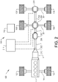
- Fig. 2 illustrate the driveline of the vehicle, or more specifically the prime mover 1, the gear box 2 and the connection to the first 20 and second 30 rear wheel axles.
- the first 20 and second 30 rear wheel axles are hence propelled wheel axles connected to the prime mover 1 and gear box 2 via a front propeller shaft 202, 202' and a rear propeller shaft 204.
- the front propeller shaft 202, 202' is arranged between the gear box 2 and the first rear wheel axle 20, and the rear propeller shaft 204 is arranged between the first rear wheel axle 20 and the second rear wheel axle 30.
- the front propeller shaft is further split into a first 202 and a second 202' front propeller shaft by means of a longitudinal differential braking arrangement 206.
- the longitudinal differential braking arrangement 206 is thus arranged to control a relative rotational speed between the first and second front propeller shafts 202, 202'.
- the vehicle 100 comprises a first differential braking arrangement 208 arranged to control a mutual rotation between the pair of first rear wheels 104, 104'.
- the first differential braking arrangement 208 may also be arranged to slip for allowing a mutual rotation between the right 104' and left 104 first rear wheels.
- the first differential braking arrangement 208 may also be arranged to connect the second front propeller shaft 202' and the rear propeller shaft 204 to each other.
- the first differential braking arrangement 208 is arranged to control whether the second rear wheel axle 30 is propelled or not.
- the vehicle 100 further comprises a second differential braking arrangement 210 connecting the second rear wheel axle 30 to the rear propeller shaft 204.
- the second differential braking arrangement 210 is arranged to control a mutual rotation between the pair of second rear wheels 106, 106'.
- the second differential braking arrangement 210 may also be arranged to slip for allowing a mutual rotation between the right 106' and left 106 second rear wheels.
- the first 208 and second 210 differential braking arrangements may each be arranged as a dog clutch or as a friction clutch.
- the vehicle 100 comprises at least one auxiliary braking arrangement 212.
- the at least one auxiliary braking arrangement 212 is in Fig. 2 schematically depicted as a gear box retarder connected to the output shaft (not shown) of the gear box 2.
- the auxiliary braking arrangement 212 is arranged to operate on the propelled wheels of vehicle 100 for reducing the speed of the vehicle 100.
- the vehicle comprises a system 201 for controlling the at least one differential braking arrangement.
- the system 201 comprising a control unit 214 connected to each of the at least one auxiliary braking arrangement 212, the longitudinal differential braking arrangement 206, the first differential braking arrangement 208, and the second differential braking arrangement 210.
- the control unit 214 is able to e.g. control engagement/disengagement of the auxiliary braking arrangement 212, the longitudinal differential braking arrangement 206, etc.
- the vehicle 100 also comprises means 216 for determining the road ahead of the vehicle 100.
- the means 216 for determining the road ahead of the vehicle 100 may e.g. be a navigation system or logged road data.
- the control unit 214 is able to determine that e.g. the vehicle 100 is approaching a downhill slope, the distance to the downhill slope as well as the inclination of the downhill slope.
- control unit 214 may also be connected to weight indication means of the vehicle and vehicle speed indication means for receiving signals indicative of the weight and speed of the vehicle.
- weight indication means may be one, or several weight sensors of the vehicle.
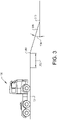
- the vehicle 100 is driven at a relatively flat, non-inclined road surface 301.
- the vehicle 100 is approaching a downhill slope 306.
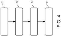
- the control unit 214 of the vehicle 100 receives S1 a signal indicative of the downhill slope 306.
- the control unit 214 also determines a distance ahead of the vehicle before the vehicle arrives at the crest 308 of the downhill slope 306.
- the control unit 214 may determine both the distance to the crest 308 of the downhill slope 306 as well as the time period until the vehicle 100 arrives at the crest 308 of the downhill slope 306.
- control unit 214 also determines S2 an inclination 304 of the downhill slope 306.
- the inclination 304 may, for example, be a mean value of the inclination which is measured from the crest 308 of the downhill slope to the end 310 of the downhill slope 306.
- the inclination 304 may also relate to a maximum inclination of the downhill slope 306, which maximum inclination is measured somewhere along the downhill slope 306 between the crest 308 of the downhill slope 306 and the end 310 of the downhill slope 306.
- the control unit 214 determines S3 a braking power of the at least one auxiliary braking arrangement 212 that is required for preventing the vehicle speed from exceeding a predetermined speed limit when driving the downhill slope.
- the predetermined speed limit may, for example, be the existing speed limit of the road, or a desired speed limit set by e.g. a vehicle cruise control system, etc. If the braking power required by the at least one auxiliary braking arrangement 212 is determined to be higher than a predetermined threshold limit, the control unit 214 thereafter controls the at least one differential braking arrangement 208, 210 to be engaged S4 before the vehicle 100 arrives at the crest 308 of the downhill slope 304. When the at least one differential braking arrangement 208, 210 is engaged, the relative rotational speed between the pair of propelled wheels 104, 104', 106, 106' is reduced.
- the at least one auxiliary braking arrangement 212 When the vehicle 100 thereafter is driven at the downhill slope 306, the at least one auxiliary braking arrangement 212 is positioned in the engaged state for preventing the vehicle speed from exceeding the predetermined speed limit. After the vehicle has driven past the end 310 of the downhill slope 306, the at least one auxiliary braking arrangement 212 may be disengaged and subsequently the at least one differential braking arrangement 208, 210 is disengaged.
- control unit 214 may control the at least one auxiliary braking arrangement 212 to be disengaged for a short duration of time at which the at least one differential braking arrangement 208, 210 can be engaged, where after the at least one auxiliary braking arrangement 212 is re-engaged.
- the above described braking power of the at least one auxiliary braking arrangement 212 that is required for preventing the vehicle speed from exceeding a predetermined speed limit can be further based on the weight of the vehicle 100 and/or a current vehicle speed.
- an increased braking power may be required if the weight of the vehicle 100 is high.
- An increased braking power may also be required if the current vehicle speed is substantially higher than the predetermined speed limit, i.e. the vehicle speed must be substantially reduced.
- the predetermined threshold limit for the braking power of the at least one auxiliary braking arrangement 212 may also be based on the vehicle weight, a current vehicle speed and/or the inclination of the downhill slope.
- the predetermined threshold limit for the braking power may also be based on an ambient temperature outside the vehicle 100 and/or road surface characteristic of the downhill slope.
- the control unit 214 is thus arranged to receive signals indicative of the above described parameters for determining the braking power and predetermined threshold limit for the braking power.
Landscapes
- Engineering & Computer Science (AREA)
- Mechanical Engineering (AREA)
- Transportation (AREA)
- General Engineering & Computer Science (AREA)
- Automation & Control Theory (AREA)
- Chemical & Material Sciences (AREA)
- Combustion & Propulsion (AREA)
- Electric Propulsion And Braking For Vehicles (AREA)
- Regulating Braking Force (AREA)
- Control Of Transmission Device (AREA)
Description
- The invention relates to a method for controlling a differential braking arrangement of a vehicle. The invention also relates to a system for controlling a differential braking arrangement, and a vehicle comprising such a system. The invention is preferably applicable on heavy duty vehicles commonly referred to as trucks. However, the invention may also be applicable for any other vehicle comprising auxiliary braking arrangements and differential braking arrangements.
- In connection to low-, medium and heavy duty vehicles, also commonly referred to as trucks, there is always a high demand on the vehicle brakes. These demands relate in particular to the braking capability for the vehicle as the vehicle brakes need to function properly in order to sufficiently reduce the vehicle speed.
- For example, when driving at a relatively steep downhill slope, where braking is necessary to prevent the vehicle from exceeding a predetermined allowable speed limit, there is of particular relevance that the vehicle brakes function properly. In such situation, an auxiliary braking arrangement of the vehicle is often utilized for reducing, or maintaining the vehicle speed. Hereby, a reduction of wheel brake wear is achieved since the wheel brakes, i.e. the service brakes, does not have to be fully utilized. It is thus important to control the auxiliary braking arrangement properly for sufficiently controlling the speed of the vehicle when driving the downhill slope. An example of a downhill speed control system having control means for controlling the strength of applied brake, when a vehicle equipped with auxiliary braking arrangement runs down a slope is disclosed in
US 2005 0096 183 A1 . - However, when engaging the auxiliary braking arrangement, there is a risk that one of the wheels will slip relative the other wheels. Accordingly, there is a desire to improve the control of the vehicle during an event when engaging the auxiliary braking arrangement.
- It is an object of the present invention to provide a method and a system for controlling a differential braking arrangement which at least partially overcomes the above described deficiencies. This is achieved by a method according to
independent claim 1 and a system according to independent claim 11. - According to a first aspect of the present invention, there is provided a method for controlling a differential braking arrangement of a vehicle, the vehicle comprising at least one auxiliary braking arrangement and at least one differential braking arrangement, the auxiliary braking arrangement and the differential braking arrangement being connected to a pair of propelled wheels of the vehicle, wherein the differential braking arrangement is arranged to control a relative rotational speed between the pair of propelled wheels, wherein the method comprises the steps of receiving a signal indicative of a downhill slope for a road ahead of the vehicle; determining an inclination of the downhill slope; determining, based on the determined inclination,
a braking power needed for the at least one auxiliary braking arrangement for preventing the vehicle speed of the vehicle from exceeding a predetermined speed limit when driving at the downhill slope; and engaging the at least one differential braking arrangement for reducing the relative rotational speed between the propelled wheels if the determined braking power of the at least one auxiliary braking arrangement is higher than a predetermined threshold limit, wherein the at least one differential braking arrangement is engaged when the vehicle is positioned at a predetermined distance from the downhill slope. - The wording "auxiliary braking arrangement" may relate to various braking arrangements that are not the ordinary service brake, i.e. not the wheel brake, nor the parking brake. The auxiliary braking arrangement operates on the propelled wheels of the vehicle. The auxiliary braking arrangement may, for example be a gear box retarder arrangement positioned in the gear box of the vehicle. Such gear box retarder arrangement may preferably be arranged at the rear end of the gearbox and connected to the output shaft thereof. Another example of an auxiliary braking arrangement may be an exhaust brake. The exhaust brake is operated by closing off the exhaust path from the engine. This will in turn cause the vehicle to slow down. Other alternative auxiliary braking arrangements are also conceivable.
- A differential braking arrangement on the other hand should be construed as a brake which is arranged to reduce the relative speed difference between wheels, or shafts. As will be described below, the differential braking arrangement may be designed as a dog clutch or as a friction brake.
- An advantage of the present invention is that by engaging the at least one differential braking arrangement before the vehicle arrives at the downhill slope, the at least one differential braking arrangement will not be exposed to high torque loads. The inventors of the present invention have realized that the differential braking arrangement can be engaged before arriving at the downhill slope where the at least one auxiliary braking arrangement will be engaged. As stated above, the differential braking arrangement will not be exposed to high torque loads as would be the case if the differential braking arrangement is engaged when the at least one auxiliary braking arrangement is already positioned in the engaged state for reducing the speed of the vehicle.
- By engaging the differential braking arrangement, the rotational speed of the wheels on the left hand side and the right hand side of the vehicle will be substantially the same which will reduce the risk of wheel slip when driving downhill and at the same time reducing, or maintaining the vehicle speed by means of the at least one auxiliary braking arrangement.
- Furthermore, as stated above, the at least one differential braking arrangement is engaged when the vehicle is positioned at a predetermined distance from the downhill slope. This predetermined distance may be of different length depending on the specific vehicle used. Hence, the predetermined distance may be a vehicle specific distance, or specific for various applications. Accordingly, the predetermined distance may be dependent on the road at which the vehicle is driven or the downhill slope ahead of the vehicle. The predetermined distance may also relate to the position on the crest of the downhill slope, just before the vehicle enters the downhill slope. The predetermined distance may thus also relate to a small distance before the slope exceeds a predetermined threshold value, wherein the predetermined threshold value defines an angle of the slope at which the at least one differential braking arrangement will be exposed to torque loads.
- According to an example embodiment, the method may further comprise the steps of engaging the at least one auxiliary braking arrangement when the vehicle is driven at the downhill slope after the differential braking arrangement is engaged. Hereby, the differential braking arrangement is engaged and the vehicle may thus reduce the speed, or keep the speed at a desired vehicle speed.
- According to an example embodiment, the method may further comprise the steps of disengaging the at least one auxiliary braking arrangement after the vehicle has driven at the downhill slope; and subsequently disengaging the at least one differential braking arrangement. Thus, the differential braking arrangement is kept engaged for the full time period when the auxiliary braking arrangement is engaged. Hereby, the differential braking arrangement will be disengaged when not being exposed to torque loads.
- According to an example embodiment, the step of engaging the at least one differential braking arrangement may be preceded by the steps of determining that the at least one auxiliary braking arrangement is engaged and the vehicle is driven at a road having an inclination lower than a predetermined angular threshold limit; and disengaging the at least one auxiliary braking arrangement before the vehicle is positioned at the predetermined distance from the downhill slope. Hereby, the auxiliary braking arrangement can be disengaged for a short time period, at which time period the differential braking arrangement can be engaged, where after the auxiliary braking arrangement is engaged.
- According to an example embodiment, the method may further comprise the steps of determining a weight of the vehicle; determining a current vehicle speed; and determining the braking power based on the determined weight of the vehicle and the current vehicle speed. The weight of the vehicle may preferably relate to the total weight of the vehicle.
- According to an example embodiment, the predetermined threshold limit for the braking power may be based on at least one of a vehicle weight, current vehicle speed and inclination of the downhill slope. Hence, the predetermined threshold limit may be an adaptive threshold limit which changes depending on the specific situation and circumstances for the vehicle. Hereby, the differential braking arrangement is engaged only when necessary which will further reduce wear thereof.
- According to an example embodiment, the predetermined threshold limit for the braking power may be based on at least one of an ambient temperature outside the vehicle and a road surface characteristic of the downhill slope.
- According to an example embodiment, the at least one differential braking arrangement may comprise a dog clutch, wherein the relative rotational speed between the propelled wheels is substantially zero when engaging the differential braking arrangement.
- The wording "substantially zero" should in this context be understood such as to admit rattle in the dog clutch. The dog clutch may be exposed to such rattle when, for example, being exposed to low torque loads, or alternating torque loads.
- According to an example embodiment, the at least one differential braking arrangement may comprise a friction clutch, the at least one differential braking arrangement being engageable in a fully engaged position or a partly engaged position. A friction clutch may thus allow for a small relative difference in rotational speed between the wheels on the left hand side and the right hand side of the vehicle.
- According to an example embodiment, the step of determining the inclination of the downhill slope may be determined based on a signal received from logged road data or a navigation system. The logged data may be provided to a control unit of the vehicle from situations where the road has been driven at an earlier point in time. The logged road data may be provided to the control unit from the specific vehicle driving at the road, or provided via a suitable communication arrangement to the control unit of the vehicle.
- According to a second aspect, there is provided a system for controlling a differential braking arrangement of a vehicle, the system being connectable to a vehicle comprising at least one auxiliary braking arrangement and at least one differential braking arrangement, the auxiliary braking arrangement and the differential braking arrangement being connected to a pair of propelled wheels of the vehicle, wherein the differential braking arrangement is arranged to control a relative rotational speed between the pair of propelled wheels, wherein the system comprises a control unit configured to receive a signal indicative of a downhill slope for a road ahead of the vehicle; determine an inclination of the downhill slope; determine, based on the determined inclination, a braking power needed for the at least one auxiliary braking arrangement for preventing the vehicle speed of the vehicle to exceed a predetermined speed limit when driving at the downhill slope; and control the at least one differential braking arrangement to be engaged for reducing the relative rotational speed between the propelled wheels if the determined braking power of the at least one auxiliary braking arrangement is higher than a predetermined threshold limit, wherein the control unit controls at least one differential braking arrangement to be engaged when the vehicle is positioned at a predetermined distance from the downhill slope.
- The control unit is thus arranged to control a variety of vehicle functionalities. The control unit may be specifically arranged to control the above described system or may be a control unit which also controls other functionalities of the vehicle. The control unit may further be arranged to receive a signal indicative of a distance to the downhill slope.
- Effects and features of the second aspect are largely analogous to those described above in relation to the first aspect.
- According to a third aspect, there is provided a vehicle comprising at least one pair of propelled wheels, at least one auxiliary braking arrangement and at least one differential braking arrangement connected to the pair of propelled wheels, wherein the differential braking arrangement is arranged to control a relative rotational speed between the pair of propelled wheels, wherein the vehicle further comprises a system as described above in relation to the second aspect.
- According to a fourth aspect, there is provided a computer program comprising program code means for performing any of the steps described above in relation to the first aspect when the program is run on a computer.
- According to a fifth aspect, there is provided a computer readable medium carrying a computer program comprising program means for performing any of the steps described above in relation to the first aspect when the program means is run on a computer.
- Further features of, and advantages with, the present invention will become apparent when studying the appended claims and the following description. The skilled person will realize that different features of the present invention may be combined to create embodiments other than those described in the following, without departing from the scope of the present invention.
- The above, as well as additional objects, features and advantages of the present invention, will be better understood through the following illustrative and non-limiting detailed description of exemplary embodiments of the present invention, wherein:
-
Fig. 1 is a lateral side view illustrating an example embodiment of a vehicle in the form of a truck; -
Fig. 2 is a schematic illustration of an example embodiment of the driveline of the vehicle inFig. 1 ; -
Fig. 3 illustrates the vehicle approaching a downhill slope; and -
Fig. 4 is flow chart of a method according to an example embodiment. - The present invention will now be described more fully hereinafter with reference to the accompanying drawings, in which exemplary embodiments of the invention are shown. The invention may, however, be embodied in many different forms and should not be construed as limited to the embodiments set forth herein; rather, these embodiments are provided for thoroughness and completeness. Like reference character refer to like elements throughout the description.
- With particular reference to
Fig. 1 , there is provided avehicle 100 in the form of a truck for which the method of the present invention can be applicable. As can be seen, thevehicle 100 comprises aprime mover 1, here in the form of an internal combustion engine, and agear box 2 connected downstream theprime mover 1. Thevehicle 100 also comprises afront wheel axle 10 comprising a pair of front,steerable wheels 102, 102'. Thefront wheel axle 10 may be either a non-propelled wheel axle or a propelled wheel axle. Thevehicle 100 further comprises a firstrear wheel axle 20 and a secondrear wheel axle 30, where the firstrear wheel axle 20 is positioned in front of the secondrear wheel axle 30 as seen in the longitudinal forward driving direction of thevehicle 100. The first 20 and second 30 rear wheel axles may be propelled wheel axles as will be described further below. Also, the firstrear wheel axle 20 comprises a pair of firstrear wheels 104, 104' and the secondrear wheel axle 30 comprises a pair of secondrear wheels 106, 106'. The pair of wheels thus comprises onewheel vehicle 100 and one wheel 104', 106' arranged on the right hand side of thevehicle 100 as seen in the longitudinal forward driving direction of thevehicle 100. - Reference is made to
Fig. 2 , which illustrate the driveline of the vehicle, or more specifically theprime mover 1, thegear box 2 and the connection to the first 20 and second 30 rear wheel axles. In the example embodiment depicted inFig. 2 , the first 20 and second 30 rear wheel axles are hence propelled wheel axles connected to theprime mover 1 andgear box 2 via afront propeller shaft 202, 202' and arear propeller shaft 204. Thefront propeller shaft 202, 202' is arranged between thegear box 2 and the firstrear wheel axle 20, and therear propeller shaft 204 is arranged between the firstrear wheel axle 20 and the secondrear wheel axle 30. The front propeller shaft is further split into a first 202 and a second 202' front propeller shaft by means of a longitudinaldifferential braking arrangement 206. The longitudinaldifferential braking arrangement 206 is thus arranged to control a relative rotational speed between the first and secondfront propeller shafts 202, 202'. - Furthermore, the
vehicle 100 comprises a first differential braking arrangement 208 arranged to control a mutual rotation between the pair of firstrear wheels 104, 104'. Hence, when the first differential braking arrangement 208 is engaged, the relative rotational speed between the right 104' and left 104 first rear wheels is substantially zero. The first differential braking arrangement 208 may also be arranged to slip for allowing a mutual rotation between the right 104' and left 104 first rear wheels. The first differential braking arrangement 208 may also be arranged to connect the second front propeller shaft 202' and therear propeller shaft 204 to each other. Hereby, the first differential braking arrangement 208 is arranged to control whether the secondrear wheel axle 30 is propelled or not. - Moreover, the
vehicle 100 further comprises a seconddifferential braking arrangement 210 connecting the secondrear wheel axle 30 to therear propeller shaft 204. The seconddifferential braking arrangement 210 is arranged to control a mutual rotation between the pair of secondrear wheels 106, 106'. Hence, when the seconddifferential braking arrangement 210 is engaged, the relative rotational speed between the right 106' and left 106 second rear wheels is substantially zero. The seconddifferential braking arrangement 210 may also be arranged to slip for allowing a mutual rotation between the right 106' and left 106 second rear wheels. - The first 208 and second 210 differential braking arrangements may each be arranged as a dog clutch or as a friction clutch.
- Still further, the
vehicle 100 comprises at least oneauxiliary braking arrangement 212. The at least oneauxiliary braking arrangement 212 is inFig. 2 schematically depicted as a gear box retarder connected to the output shaft (not shown) of thegear box 2. Theauxiliary braking arrangement 212 is arranged to operate on the propelled wheels ofvehicle 100 for reducing the speed of thevehicle 100. - As is further depicted in
Fig. 2 , the vehicle comprises asystem 201 for controlling the at least one differential braking arrangement. Thesystem 201 comprising acontrol unit 214 connected to each of the at least oneauxiliary braking arrangement 212, the longitudinaldifferential braking arrangement 206, the first differential braking arrangement 208, and the seconddifferential braking arrangement 210. By means of the connection between thecontrol unit 214 and each of the at least oneauxiliary braking arrangement 212, the longitudinaldifferential braking arrangement 206, the first differential braking arrangement 208, and the seconddifferential braking arrangement 210, thecontrol unit 214 is able to e.g. control engagement/disengagement of theauxiliary braking arrangement 212, the longitudinaldifferential braking arrangement 206, etc. - Still further, the
vehicle 100 also comprisesmeans 216 for determining the road ahead of thevehicle 100. The means 216 for determining the road ahead of thevehicle 100 may e.g. be a navigation system or logged road data. By using themeans 216 for determining the road ahead of thevehicle 100, thecontrol unit 214 is able to determine that e.g. thevehicle 100 is approaching a downhill slope, the distance to the downhill slope as well as the inclination of the downhill slope. - As not depicted in
Fig. 2 , thecontrol unit 214 may also be connected to weight indication means of the vehicle and vehicle speed indication means for receiving signals indicative of the weight and speed of the vehicle. Such weight indication means may be one, or several weight sensors of the vehicle. - In order to describe an example embodiment of controlling at least one of the above described
differential braking arrangements Figs. 3 and4 . - As depicted in
Fig. 3 , thevehicle 100 is driven at a relatively flat,non-inclined road surface 301. However, thevehicle 100 is approaching adownhill slope 306. Hereby, thecontrol unit 214 of thevehicle 100 receives S1 a signal indicative of thedownhill slope 306. Thecontrol unit 214 also determines a distance ahead of the vehicle before the vehicle arrives at thecrest 308 of thedownhill slope 306. Thecontrol unit 214 may determine both the distance to thecrest 308 of thedownhill slope 306 as well as the time period until thevehicle 100 arrives at thecrest 308 of thedownhill slope 306. - Furthermore, the
control unit 214 also determines S2 aninclination 304 of thedownhill slope 306. Theinclination 304 may, for example, be a mean value of the inclination which is measured from thecrest 308 of the downhill slope to theend 310 of thedownhill slope 306. Theinclination 304 may also relate to a maximum inclination of thedownhill slope 306, which maximum inclination is measured somewhere along thedownhill slope 306 between thecrest 308 of thedownhill slope 306 and theend 310 of thedownhill slope 306. - Moreover, based on the determination of the
inclination 304 of thedownhill slope 306, thecontrol unit 214 determines S3 a braking power of the at least oneauxiliary braking arrangement 212 that is required for preventing the vehicle speed from exceeding a predetermined speed limit when driving the downhill slope. The predetermined speed limit may, for example, be the existing speed limit of the road, or a desired speed limit set by e.g. a vehicle cruise control system, etc. If the braking power required by the at least oneauxiliary braking arrangement 212 is determined to be higher than a predetermined threshold limit, thecontrol unit 214 thereafter controls the at least onedifferential braking arrangement 208, 210 to be engaged S4 before thevehicle 100 arrives at thecrest 308 of thedownhill slope 304. When the at least onedifferential braking arrangement 208, 210 is engaged, the relative rotational speed between the pair of propelledwheels - When the
vehicle 100 thereafter is driven at thedownhill slope 306, the at least oneauxiliary braking arrangement 212 is positioned in the engaged state for preventing the vehicle speed from exceeding the predetermined speed limit. After the vehicle has driven past theend 310 of thedownhill slope 306, the at least oneauxiliary braking arrangement 212 may be disengaged and subsequently the at least onedifferential braking arrangement 208, 210 is disengaged. - If the
vehicle 100 is driven at a downhill slope and having the at least oneauxiliary braking arrangement 212 engaged and the at least onedifferential braking arrangement 208, 210 is disengaged, thecontrol unit 214 may control the at least oneauxiliary braking arrangement 212 to be disengaged for a short duration of time at which the at least onedifferential braking arrangement 208, 210 can be engaged, where after the at least oneauxiliary braking arrangement 212 is re-engaged. - The above described braking power of the at least one
auxiliary braking arrangement 212 that is required for preventing the vehicle speed from exceeding a predetermined speed limit can be further based on the weight of thevehicle 100 and/or a current vehicle speed. Thus, an increased braking power may be required if the weight of thevehicle 100 is high. An increased braking power may also be required if the current vehicle speed is substantially higher than the predetermined speed limit, i.e. the vehicle speed must be substantially reduced. Furthermore, the predetermined threshold limit for the braking power of the at least oneauxiliary braking arrangement 212 may also be based on the vehicle weight, a current vehicle speed and/or the inclination of the downhill slope. The predetermined threshold limit for the braking power may also be based on an ambient temperature outside thevehicle 100 and/or road surface characteristic of the downhill slope. Thecontrol unit 214 is thus arranged to receive signals indicative of the above described parameters for determining the braking power and predetermined threshold limit for the braking power. - It is to be understood that the present invention is not limited to the embodiments described above and illustrated in the drawings; rather, the skilled person will recognize that many changes and modifications may be made within the scope of the appended claims.
Claims (14)
- A method for controlling a differential braking arrangement (208, 210) of a vehicle (100), said vehicle (100) comprising at least one auxiliary braking arrangement (212) and at least one differential braking arrangement (208, 210), said auxiliary braking arrangement (212) and said differential braking arrangement (208, 210) being connected to a pair of propelled wheels (104, 104', 106, 106') of said vehicle (100), wherein the differential braking arrangement (208, 210) is arranged to control a relative rotational speed between the pair of propelled wheels (104, 104', 106, 106'), the method being characterized by the steps of:- receiving (S1) a signal indicative of a downhill slope (306) for a road ahead of said vehicle (100);- determining (S2) an inclination (304) of said downhill slope (306);- determining (S3), based on the determined inclination (304), a braking power needed for the at least one auxiliary braking arrangement (212) for preventing the vehicle speed of the vehicle (100) from exceeding a predetermined speed limit when driving at the downhill slope (306); and- engaging (S4) the at least one differential braking arrangement (212) for reducing the relative rotational speed between the propelled wheels (104, 104', 106, 106') if the determined braking power of the at least one auxiliary braking arrangement (212) is higher than a predetermined threshold limit, wherein the at least one differential braking arrangement (208, 210) is engaged when the vehicle (100) is positioned at a predetermined distance (302) from the downhill slope (306).
- The method according to claim 1, further comprising the step of:- engaging the at least one auxiliary braking arrangement (212) when the vehicle (100) is driven at the downhill slope (306) after said differential braking arrangement (208, 210) is engaged.
- The method according to claim 2, further comprising the steps of:- disengaging the at least one auxiliary braking arrangement (212) after the vehicle (100) has driven at the downhill slope (306); and subsequently- disengaging the at least one differential braking arrangement (208, 210).
- The method according to any one of the preceding claims, wherein the step of engaging the at least one differential braking arrangement (208, 210) is preceded by the steps of:- determining that the at least one auxiliary braking arrangement (212) is engaged and the vehicle (100) is driven at a road having an inclination lower than a predetermined angular threshold limit; and- disengaging the at least one auxiliary braking arrangement (212) before the vehicle (100) is positioned at the predetermined distance (302) from the downhill slope (306).
- The method according to any one of the preceding claims, further comprising the steps of:- determining a weight of the vehicle (100);- determining a current vehicle speed; and- determining the braking power based on the determined weight of the vehicle (100) and the current vehicle speed.
- The method according to any one of the preceding claims, wherein the predetermined threshold limit for the braking power is based on at least one of a vehicle weight, current vehicle speed and inclination of the downhill slope.
- The method according to any one of the preceding claims, wherein the predetermined threshold limit for the braking power is based on at least one of an ambient temperature outside the vehicle and a road surface characteristic of the downhill slope.
- The method according to any one of the preceding claims, wherein the at least one differential braking arrangement (208, 210) comprises a dog clutch, wherein the relative rotational speed between the propelled wheels (104, 104', 106, 106') is substantially zero when engaging the differential braking arrangement (208, 210).
- The method according to any one of claims 1 - 7, wherein the at least one differential braking arrangement (208, 210) comprises a friction clutch, said at least one differential braking arrangement (208, 210) being engageable in a fully engaged position or a partly engaged position.
- The method according to any one of the preceding claims, wherein the step of determining the inclination (304) of the downhill slope (306) is determined based a signal received from logged road data or a navigation system.
- A system (201) for controlling a differential braking arrangement (208, 210) of a vehicle (100), said system (201) being connectable to a vehicle (100) comprising at least one auxiliary braking arrangement (212) and at least one differential braking arrangement (208, 210), said auxiliary braking arrangement (212) and said differential braking arrangement (208, 210) being connected to a pair of propelled wheels (104, 104', 106, 106') of said vehicle (100), wherein the differential braking arrangement is arranged to control a relative rotational speed between the pair of propelled wheels (104, 104', 106, 106'), characterized in that the system (201) comprises a control unit (214) configured to:- receive (S1) a signal indicative of a downhill slope (306) for a road ahead of said vehicle (100);- determine (S2) an inclination (304) of said downhill slope (306);- determine (S3), based on the determined inclination (304), a braking power needed for the at least one auxiliary braking arrangement (212) for preventing the vehicle speed of the vehicle (100) to exceed a predetermined speed limit when driving at the downhill slope (306); and- control the at least one differential braking arrangement to be engaged (S4) for reducing the relative rotational speed between the propelled wheels if the determined braking power of the at least one auxiliary braking arrangement is higher than a predetermined threshold limit, wherein the control unit controls at least one differential braking arrangement to be engaged when the vehicle is positioned at a predetermined distance from the downhill slope.
- A vehicle (100) comprising at least one pair of propelled wheels (104, 104', 106, 106'), at least one auxiliary braking arrangement (212) and at least one differential braking arrangement (208, 210) connected to said pair of propelled wheels (104, 104', 106, 106'), wherein the differential braking arrangement (208, 210) is arranged to control a relative rotational speed between the pair of propelled wheels (104, 104', 106, 106'), wherein the vehicle further comprises a system (201) according to claim 11.
- A computer program comprising program code means for performing the steps of any one of claims 1 - 10 when said program is run on a computer.
- A computer readable medium carrying a computer program comprising program means for performing the steps of any one of claims 1 - 10 when said program means is run on a computer.
Applications Claiming Priority (1)
| Application Number | Priority Date | Filing Date | Title |
|---|---|---|---|
| PCT/EP2017/064164 WO2018224171A1 (en) | 2017-06-09 | 2017-06-09 | A method for controlling a differential braking arrangement |
Publications (2)
| Publication Number | Publication Date |
|---|---|
| EP3634825A1 EP3634825A1 (en) | 2020-04-15 |
| EP3634825B1 true EP3634825B1 (en) | 2022-08-31 |
Family
ID=59054120
Family Applications (1)
| Application Number | Title | Priority Date | Filing Date |
|---|---|---|---|
| EP17729460.0A Active EP3634825B1 (en) | 2017-06-09 | 2017-06-09 | A method for controlling a differential braking arrangement |
Country Status (4)
| Country | Link |
|---|---|
| US (1) | US10948064B2 (en) |
| EP (1) | EP3634825B1 (en) |
| CN (1) | CN110709299B (en) |
| WO (1) | WO2018224171A1 (en) |
Cited By (1)
| Publication number | Priority date | Publication date | Assignee | Title |
|---|---|---|---|---|
| DE102025103123B3 (en) | 2025-01-29 | 2026-05-07 | Audi Aktiengesellschaft | Methods for improving energy recuperation in an electric vehicle |
Families Citing this family (11)
| Publication number | Priority date | Publication date | Assignee | Title |
|---|---|---|---|---|
| CN112654578B (en) | 2018-09-13 | 2023-03-14 | 克朗设备公司 | System and method for controlling maximum vehicle speed of industrial vehicle based on calculated load |
| US11001247B2 (en) * | 2019-04-08 | 2021-05-11 | GM Global Technology Operations LLC | Method for suggesting activation of an exhaust brake |
| US11242098B2 (en) * | 2019-07-26 | 2022-02-08 | Waymo Llc | Efficient autonomous trucks |
| WO2021248495A1 (en) * | 2020-06-12 | 2021-12-16 | Qualcomm Incorporated | Application layer messages for lane description in vehicular communication |
| CN113954798B (en) * | 2020-07-21 | 2025-11-28 | 厦门雅迅智联科技股份有限公司 | Control method and control system of hydraulic retarder |
| CN112598917A (en) * | 2020-11-09 | 2021-04-02 | 武汉光庭科技有限公司 | Gear speed control method and system based on road information prediction |
| CN113879301B (en) * | 2021-10-19 | 2023-06-23 | 中寰卫星导航通信有限公司 | Vehicle control method, device, equipment and storage medium |
| CN116409338A (en) * | 2021-12-30 | 2023-07-11 | 魔门塔(苏州)科技有限公司 | Slope-based automatic driving speed planning method, device, medium and equipment |
| CN116118733B (en) * | 2022-12-21 | 2025-06-13 | 中联重科股份有限公司 | Braking control method, device and wheel crane |
| FR3152746B1 (en) * | 2023-09-12 | 2025-08-15 | Psa Automobiles Sa | METHOD FOR CONTROLLING A LOCKING SPEED DIFFERENTIAL OF A REAR WHEEL ASSEMBLY |
| EP4570609A1 (en) * | 2023-12-14 | 2025-06-18 | Volvo Truck Corporation | Handling differentials in a vehicle |
Family Cites Families (13)
| Publication number | Priority date | Publication date | Assignee | Title |
|---|---|---|---|---|
| US6076898A (en) | 1997-04-18 | 2000-06-20 | Aisin Seiki Kabushiki Kaisha | Braking control system for a four-wheel drive vehicle |
| US6085138A (en) | 1998-11-12 | 2000-07-04 | Caterpillar Inc. | Differential lock control system |
| JP2002087095A (en) | 2000-09-12 | 2002-03-26 | Komatsu Ltd | Vehicle tire lock prevention device |
| EP1557331B1 (en) | 2002-10-28 | 2011-02-23 | Hitachi Construction Machinery Co., Ltd | Downhill speed controller |
| SE530039C2 (en) * | 2006-05-26 | 2008-02-12 | Scania Cv Abp | System and method for controlling braking of a downhill motor vehicle |
| EP2146885B1 (en) | 2007-05-10 | 2014-07-23 | Volvo Construction Equipment AB | A method for controlling a work machine during operation in a repeated work cycle |
| DE102009046341B4 (en) * | 2009-11-03 | 2021-08-26 | Zf Friedrichshafen Ag | Method for controlling a rolling or sailing function of a vehicle and transmission control unit |
| US8401753B2 (en) * | 2009-11-23 | 2013-03-19 | Caterpillar Inc. | Automatic downhill speed control system |
| US8312956B2 (en) | 2011-02-15 | 2012-11-20 | Deere & Company | Auto inter-axle differential lock engagement for improved braking capacity |
| US8589045B2 (en) * | 2011-02-18 | 2013-11-19 | Continental Automotive Systems, Inc | System and method for determining a safe maximum speed of a vehicle |
| GB2505020B (en) * | 2012-08-16 | 2015-09-09 | Jaguar Land Rover Ltd | Vehicle speed control system |
| CN104057954B (en) * | 2014-06-25 | 2017-01-11 | 徐州重型机械有限公司 | Road condition self-adaptation system of crane and crane |
| US10569775B2 (en) * | 2014-06-27 | 2020-02-25 | Volvo Truck Corporation | Arrangement and method for a cruise control brake in a vehicle |
-
2017
- 2017-06-09 US US16/615,282 patent/US10948064B2/en active Active
- 2017-06-09 CN CN201780091557.2A patent/CN110709299B/en active Active
- 2017-06-09 EP EP17729460.0A patent/EP3634825B1/en active Active
- 2017-06-09 WO PCT/EP2017/064164 patent/WO2018224171A1/en not_active Ceased
Cited By (1)
| Publication number | Priority date | Publication date | Assignee | Title |
|---|---|---|---|---|
| DE102025103123B3 (en) | 2025-01-29 | 2026-05-07 | Audi Aktiengesellschaft | Methods for improving energy recuperation in an electric vehicle |
Also Published As
| Publication number | Publication date |
|---|---|
| WO2018224171A1 (en) | 2018-12-13 |
| CN110709299A (en) | 2020-01-17 |
| CN110709299B (en) | 2022-10-14 |
| US10948064B2 (en) | 2021-03-16 |
| EP3634825A1 (en) | 2020-04-15 |
| US20200164875A1 (en) | 2020-05-28 |
Similar Documents
| Publication | Publication Date | Title |
|---|---|---|
| EP3634825B1 (en) | A method for controlling a differential braking arrangement | |
| US8380419B2 (en) | Resume speed adaptation for automatic vehicle acceleration at a rate derived from a measured acceleration rate | |
| EP2718159B1 (en) | Method and system for a vehicle | |
| EP2865914B1 (en) | Vehicle control device | |
| EP2542441B1 (en) | Drive train control arrangement | |
| EP3166829B1 (en) | Control of an combustion engine in a vehicle | |
| EP3166832B1 (en) | Control of an internal combustion engine in a vehicle | |
| EP3065967B1 (en) | Driveline and method of controlling a driveline | |
| US8930104B1 (en) | System and method for distributing torque and a powertrain using the same | |
| EP2244920B1 (en) | A method and system for braking a vehicle | |
| US9222530B2 (en) | Drive train control arrangement | |
| KR101638533B1 (en) | Method and system for control of a clutch at a vehicle | |
| US12358486B2 (en) | Method and control arrangement for changing an activation state for a power take-off | |
| US20150224971A1 (en) | Control apparatus for vehicular drive system | |
| US10625607B2 (en) | Vehicle drivetrain and clutch unit for distributing torque | |
| US10173532B2 (en) | System and method for controlling a vehicle | |
| CN103930325B (en) | For controlling the function of motor vehicles speed on the slope | |
| US10495013B2 (en) | Control of preparatory measures in a vehicle | |
| CN111032398A (en) | Method of switching between transmission modes on a hybrid motor vehicle | |
| JP4254428B2 (en) | Driving force distribution control device for four-wheel drive vehicles | |
| US10259442B2 (en) | System and method for preventing clutch burst | |
| CN102498021A (en) | Method for very low-speed rolling on a ground comprising low grip |
Legal Events
| Date | Code | Title | Description |
|---|---|---|---|
| STAA | Information on the status of an ep patent application or granted ep patent |
Free format text: STATUS: UNKNOWN |
|
| STAA | Information on the status of an ep patent application or granted ep patent |
Free format text: STATUS: THE INTERNATIONAL PUBLICATION HAS BEEN MADE |
|
| PUAI | Public reference made under article 153(3) epc to a published international application that has entered the european phase |
Free format text: ORIGINAL CODE: 0009012 |
|
| STAA | Information on the status of an ep patent application or granted ep patent |
Free format text: STATUS: REQUEST FOR EXAMINATION WAS MADE |
|
| 17P | Request for examination filed |
Effective date: 20191125 |
|
| AK | Designated contracting states |
Kind code of ref document: A1 Designated state(s): AL AT BE BG CH CY CZ DE DK EE ES FI FR GB GR HR HU IE IS IT LI LT LU LV MC MK MT NL NO PL PT RO RS SE SI SK SM TR |
|
| AX | Request for extension of the european patent |
Extension state: BA ME |
|
| DAV | Request for validation of the european patent (deleted) | ||
| DAX | Request for extension of the european patent (deleted) | ||
| GRAP | Despatch of communication of intention to grant a patent |
Free format text: ORIGINAL CODE: EPIDOSNIGR1 |
|
| STAA | Information on the status of an ep patent application or granted ep patent |
Free format text: STATUS: GRANT OF PATENT IS INTENDED |
|
| INTG | Intention to grant announced |
Effective date: 20220328 |
|
| GRAS | Grant fee paid |
Free format text: ORIGINAL CODE: EPIDOSNIGR3 |
|
| GRAA | (expected) grant |
Free format text: ORIGINAL CODE: 0009210 |
|
| STAA | Information on the status of an ep patent application or granted ep patent |
Free format text: STATUS: THE PATENT HAS BEEN GRANTED |
|
| AK | Designated contracting states |
Kind code of ref document: B1 Designated state(s): AL AT BE BG CH CY CZ DE DK EE ES FI FR GB GR HR HU IE IS IT LI LT LU LV MC MK MT NL NO PL PT RO RS SE SI SK SM TR |
|
| REG | Reference to a national code |
Ref country code: CH Ref legal event code: EP Ref country code: GB Ref legal event code: FG4D |
|
| REG | Reference to a national code |
Ref country code: AT Ref legal event code: REF Ref document number: 1515088 Country of ref document: AT Kind code of ref document: T Effective date: 20220915 Ref country code: DE Ref legal event code: R096 Ref document number: 602017061224 Country of ref document: DE |
|
| REG | Reference to a national code |
Ref country code: IE Ref legal event code: FG4D |
|
| REG | Reference to a national code |
Ref country code: LT Ref legal event code: MG9D |
|
| REG | Reference to a national code |
Ref country code: NL Ref legal event code: MP Effective date: 20220831 |
|
| PG25 | Lapsed in a contracting state [announced via postgrant information from national office to epo] |
Ref country code: SE Free format text: LAPSE BECAUSE OF FAILURE TO SUBMIT A TRANSLATION OF THE DESCRIPTION OR TO PAY THE FEE WITHIN THE PRESCRIBED TIME-LIMIT Effective date: 20220831 Ref country code: RS Free format text: LAPSE BECAUSE OF FAILURE TO SUBMIT A TRANSLATION OF THE DESCRIPTION OR TO PAY THE FEE WITHIN THE PRESCRIBED TIME-LIMIT Effective date: 20220831 Ref country code: NO Free format text: LAPSE BECAUSE OF FAILURE TO SUBMIT A TRANSLATION OF THE DESCRIPTION OR TO PAY THE FEE WITHIN THE PRESCRIBED TIME-LIMIT Effective date: 20221130 Ref country code: LV Free format text: LAPSE BECAUSE OF FAILURE TO SUBMIT A TRANSLATION OF THE DESCRIPTION OR TO PAY THE FEE WITHIN THE PRESCRIBED TIME-LIMIT Effective date: 20220831 Ref country code: LT Free format text: LAPSE BECAUSE OF FAILURE TO SUBMIT A TRANSLATION OF THE DESCRIPTION OR TO PAY THE FEE WITHIN THE PRESCRIBED TIME-LIMIT Effective date: 20220831 Ref country code: FI Free format text: LAPSE BECAUSE OF FAILURE TO SUBMIT A TRANSLATION OF THE DESCRIPTION OR TO PAY THE FEE WITHIN THE PRESCRIBED TIME-LIMIT Effective date: 20220831 |
|
| REG | Reference to a national code |
Ref country code: AT Ref legal event code: MK05 Ref document number: 1515088 Country of ref document: AT Kind code of ref document: T Effective date: 20220831 |
|
| PG25 | Lapsed in a contracting state [announced via postgrant information from national office to epo] |
Ref country code: PL Free format text: LAPSE BECAUSE OF FAILURE TO SUBMIT A TRANSLATION OF THE DESCRIPTION OR TO PAY THE FEE WITHIN THE PRESCRIBED TIME-LIMIT Effective date: 20220831 Ref country code: IS Free format text: LAPSE BECAUSE OF FAILURE TO SUBMIT A TRANSLATION OF THE DESCRIPTION OR TO PAY THE FEE WITHIN THE PRESCRIBED TIME-LIMIT Effective date: 20221231 Ref country code: HR Free format text: LAPSE BECAUSE OF FAILURE TO SUBMIT A TRANSLATION OF THE DESCRIPTION OR TO PAY THE FEE WITHIN THE PRESCRIBED TIME-LIMIT Effective date: 20220831 Ref country code: GR Free format text: LAPSE BECAUSE OF FAILURE TO SUBMIT A TRANSLATION OF THE DESCRIPTION OR TO PAY THE FEE WITHIN THE PRESCRIBED TIME-LIMIT Effective date: 20221201 |
|
| PG25 | Lapsed in a contracting state [announced via postgrant information from national office to epo] |
Ref country code: SM Free format text: LAPSE BECAUSE OF FAILURE TO SUBMIT A TRANSLATION OF THE DESCRIPTION OR TO PAY THE FEE WITHIN THE PRESCRIBED TIME-LIMIT Effective date: 20220831 Ref country code: RO Free format text: LAPSE BECAUSE OF FAILURE TO SUBMIT A TRANSLATION OF THE DESCRIPTION OR TO PAY THE FEE WITHIN THE PRESCRIBED TIME-LIMIT Effective date: 20220831 Ref country code: PT Free format text: LAPSE BECAUSE OF FAILURE TO SUBMIT A TRANSLATION OF THE DESCRIPTION OR TO PAY THE FEE WITHIN THE PRESCRIBED TIME-LIMIT Effective date: 20230102 Ref country code: ES Free format text: LAPSE BECAUSE OF FAILURE TO SUBMIT A TRANSLATION OF THE DESCRIPTION OR TO PAY THE FEE WITHIN THE PRESCRIBED TIME-LIMIT Effective date: 20220831 Ref country code: DK Free format text: LAPSE BECAUSE OF FAILURE TO SUBMIT A TRANSLATION OF THE DESCRIPTION OR TO PAY THE FEE WITHIN THE PRESCRIBED TIME-LIMIT Effective date: 20220831 Ref country code: CZ Free format text: LAPSE BECAUSE OF FAILURE TO SUBMIT A TRANSLATION OF THE DESCRIPTION OR TO PAY THE FEE WITHIN THE PRESCRIBED TIME-LIMIT Effective date: 20220831 Ref country code: AT Free format text: LAPSE BECAUSE OF FAILURE TO SUBMIT A TRANSLATION OF THE DESCRIPTION OR TO PAY THE FEE WITHIN THE PRESCRIBED TIME-LIMIT Effective date: 20220831 |
|
| PG25 | Lapsed in a contracting state [announced via postgrant information from national office to epo] |
Ref country code: SK Free format text: LAPSE BECAUSE OF FAILURE TO SUBMIT A TRANSLATION OF THE DESCRIPTION OR TO PAY THE FEE WITHIN THE PRESCRIBED TIME-LIMIT Effective date: 20220831 Ref country code: EE Free format text: LAPSE BECAUSE OF FAILURE TO SUBMIT A TRANSLATION OF THE DESCRIPTION OR TO PAY THE FEE WITHIN THE PRESCRIBED TIME-LIMIT Effective date: 20220831 |
|
| REG | Reference to a national code |
Ref country code: DE Ref legal event code: R097 Ref document number: 602017061224 Country of ref document: DE |
|
| PG25 | Lapsed in a contracting state [announced via postgrant information from national office to epo] |
Ref country code: NL Free format text: LAPSE BECAUSE OF FAILURE TO SUBMIT A TRANSLATION OF THE DESCRIPTION OR TO PAY THE FEE WITHIN THE PRESCRIBED TIME-LIMIT Effective date: 20220831 Ref country code: AL Free format text: LAPSE BECAUSE OF FAILURE TO SUBMIT A TRANSLATION OF THE DESCRIPTION OR TO PAY THE FEE WITHIN THE PRESCRIBED TIME-LIMIT Effective date: 20220831 |
|
| PLBE | No opposition filed within time limit |
Free format text: ORIGINAL CODE: 0009261 |
|
| STAA | Information on the status of an ep patent application or granted ep patent |
Free format text: STATUS: NO OPPOSITION FILED WITHIN TIME LIMIT |
|
| 26N | No opposition filed |
Effective date: 20230601 |
|
| PG25 | Lapsed in a contracting state [announced via postgrant information from national office to epo] |
Ref country code: SI Free format text: LAPSE BECAUSE OF FAILURE TO SUBMIT A TRANSLATION OF THE DESCRIPTION OR TO PAY THE FEE WITHIN THE PRESCRIBED TIME-LIMIT Effective date: 20220831 |
|
| PG25 | Lapsed in a contracting state [announced via postgrant information from national office to epo] |
Ref country code: MC Free format text: LAPSE BECAUSE OF FAILURE TO SUBMIT A TRANSLATION OF THE DESCRIPTION OR TO PAY THE FEE WITHIN THE PRESCRIBED TIME-LIMIT Effective date: 20220831 |
|
| PG25 | Lapsed in a contracting state [announced via postgrant information from national office to epo] |
Ref country code: MC Free format text: LAPSE BECAUSE OF FAILURE TO SUBMIT A TRANSLATION OF THE DESCRIPTION OR TO PAY THE FEE WITHIN THE PRESCRIBED TIME-LIMIT Effective date: 20220831 |
|
| REG | Reference to a national code |
Ref country code: CH Ref legal event code: PL |
|
| REG | Reference to a national code |
Ref country code: BE Ref legal event code: MM Effective date: 20230630 |
|
| GBPC | Gb: european patent ceased through non-payment of renewal fee |
Effective date: 20230609 |
|
| PG25 | Lapsed in a contracting state [announced via postgrant information from national office to epo] |
Ref country code: LU Free format text: LAPSE BECAUSE OF NON-PAYMENT OF DUE FEES Effective date: 20230609 |
|
| REG | Reference to a national code |
Ref country code: IE Ref legal event code: MM4A |
|
| PG25 | Lapsed in a contracting state [announced via postgrant information from national office to epo] |
Ref country code: LU Free format text: LAPSE BECAUSE OF NON-PAYMENT OF DUE FEES Effective date: 20230609 |
|
| PG25 | Lapsed in a contracting state [announced via postgrant information from national office to epo] |
Ref country code: IE Free format text: LAPSE BECAUSE OF NON-PAYMENT OF DUE FEES Effective date: 20230609 |
|
| PG25 | Lapsed in a contracting state [announced via postgrant information from national office to epo] |
Ref country code: IE Free format text: LAPSE BECAUSE OF NON-PAYMENT OF DUE FEES Effective date: 20230609 Ref country code: GB Free format text: LAPSE BECAUSE OF NON-PAYMENT OF DUE FEES Effective date: 20230609 Ref country code: CH Free format text: LAPSE BECAUSE OF NON-PAYMENT OF DUE FEES Effective date: 20230630 |
|
| PG25 | Lapsed in a contracting state [announced via postgrant information from national office to epo] |
Ref country code: IT Free format text: LAPSE BECAUSE OF FAILURE TO SUBMIT A TRANSLATION OF THE DESCRIPTION OR TO PAY THE FEE WITHIN THE PRESCRIBED TIME-LIMIT Effective date: 20220831 Ref country code: BE Free format text: LAPSE BECAUSE OF NON-PAYMENT OF DUE FEES Effective date: 20230630 |
|
| PGFP | Annual fee paid to national office [announced via postgrant information from national office to epo] |
Ref country code: FR Payment date: 20240625 Year of fee payment: 8 |
|
| PG25 | Lapsed in a contracting state [announced via postgrant information from national office to epo] |
Ref country code: BG Free format text: LAPSE BECAUSE OF FAILURE TO SUBMIT A TRANSLATION OF THE DESCRIPTION OR TO PAY THE FEE WITHIN THE PRESCRIBED TIME-LIMIT Effective date: 20220831 |
|
| PG25 | Lapsed in a contracting state [announced via postgrant information from national office to epo] |
Ref country code: BG Free format text: LAPSE BECAUSE OF FAILURE TO SUBMIT A TRANSLATION OF THE DESCRIPTION OR TO PAY THE FEE WITHIN THE PRESCRIBED TIME-LIMIT Effective date: 20220831 |
|
| PGFP | Annual fee paid to national office [announced via postgrant information from national office to epo] |
Ref country code: DE Payment date: 20250626 Year of fee payment: 9 |
|
| PG25 | Lapsed in a contracting state [announced via postgrant information from national office to epo] |
Ref country code: CY Free format text: LAPSE BECAUSE OF FAILURE TO SUBMIT A TRANSLATION OF THE DESCRIPTION OR TO PAY THE FEE WITHIN THE PRESCRIBED TIME-LIMIT; INVALID AB INITIO Effective date: 20170609 |
|
| PG25 | Lapsed in a contracting state [announced via postgrant information from national office to epo] |
Ref country code: HU Free format text: LAPSE BECAUSE OF FAILURE TO SUBMIT A TRANSLATION OF THE DESCRIPTION OR TO PAY THE FEE WITHIN THE PRESCRIBED TIME-LIMIT; INVALID AB INITIO Effective date: 20170609 |
|
| PG25 | Lapsed in a contracting state [announced via postgrant information from national office to epo] |
Ref country code: TR Free format text: LAPSE BECAUSE OF FAILURE TO SUBMIT A TRANSLATION OF THE DESCRIPTION OR TO PAY THE FEE WITHIN THE PRESCRIBED TIME-LIMIT Effective date: 20220831 |
|
| PG25 | Lapsed in a contracting state [announced via postgrant information from national office to epo] |
Ref country code: FR Free format text: LAPSE BECAUSE OF NON-PAYMENT OF DUE FEES Effective date: 20250630 |