EP3634575B1 - Apparatus for scanning laser therapy - Google Patents
Apparatus for scanning laser therapy Download PDFInfo
- Publication number
- EP3634575B1 EP3634575B1 EP18735405.5A EP18735405A EP3634575B1 EP 3634575 B1 EP3634575 B1 EP 3634575B1 EP 18735405 A EP18735405 A EP 18735405A EP 3634575 B1 EP3634575 B1 EP 3634575B1
- Authority
- EP
- European Patent Office
- Prior art keywords
- laser
- temperature
- basis
- patient
- parameters
- Prior art date
- Legal status (The legal status is an assumption and is not a legal conclusion. Google has not performed a legal analysis and makes no representation as to the accuracy of the status listed.)
- Active
Links
Images




Classifications
-
- A—HUMAN NECESSITIES
- A61—MEDICAL OR VETERINARY SCIENCE; HYGIENE
- A61N—ELECTROTHERAPY; MAGNETOTHERAPY; RADIATION THERAPY; ULTRASOUND THERAPY
- A61N5/00—Radiation therapy
- A61N5/06—Radiation therapy using light
- A61N5/0613—Apparatus adapted for a specific treatment
- A61N5/0616—Skin treatment other than tanning
-
- A—HUMAN NECESSITIES
- A61—MEDICAL OR VETERINARY SCIENCE; HYGIENE
- A61N—ELECTROTHERAPY; MAGNETOTHERAPY; RADIATION THERAPY; ULTRASOUND THERAPY
- A61N5/00—Radiation therapy
- A61N5/06—Radiation therapy using light
- A61N5/0613—Apparatus adapted for a specific treatment
-
- A—HUMAN NECESSITIES
- A61—MEDICAL OR VETERINARY SCIENCE; HYGIENE
- A61N—ELECTROTHERAPY; MAGNETOTHERAPY; RADIATION THERAPY; ULTRASOUND THERAPY
- A61N5/00—Radiation therapy
- A61N5/01—Devices for producing movement of radiation source during therapy
-
- A—HUMAN NECESSITIES
- A61—MEDICAL OR VETERINARY SCIENCE; HYGIENE
- A61N—ELECTROTHERAPY; MAGNETOTHERAPY; RADIATION THERAPY; ULTRASOUND THERAPY
- A61N5/00—Radiation therapy
- A61N5/06—Radiation therapy using light
- A61N5/0613—Apparatus adapted for a specific treatment
- A61N5/0624—Apparatus adapted for a specific treatment for eliminating microbes, germs, bacteria on or in the body
-
- A—HUMAN NECESSITIES
- A61—MEDICAL OR VETERINARY SCIENCE; HYGIENE
- A61N—ELECTROTHERAPY; MAGNETOTHERAPY; RADIATION THERAPY; ULTRASOUND THERAPY
- A61N5/00—Radiation therapy
- A61N5/06—Radiation therapy using light
- A61N5/067—Radiation therapy using light using laser light
-
- A—HUMAN NECESSITIES
- A61—MEDICAL OR VETERINARY SCIENCE; HYGIENE
- A61N—ELECTROTHERAPY; MAGNETOTHERAPY; RADIATION THERAPY; ULTRASOUND THERAPY
- A61N5/00—Radiation therapy
- A61N5/06—Radiation therapy using light
- A61N2005/0626—Monitoring, verifying, controlling systems and methods
-
- A—HUMAN NECESSITIES
- A61—MEDICAL OR VETERINARY SCIENCE; HYGIENE
- A61N—ELECTROTHERAPY; MAGNETOTHERAPY; RADIATION THERAPY; ULTRASOUND THERAPY
- A61N5/00—Radiation therapy
- A61N5/06—Radiation therapy using light
- A61N2005/0626—Monitoring, verifying, controlling systems and methods
- A61N2005/0627—Dose monitoring systems and methods
- A61N2005/0628—Dose monitoring systems and methods including a radiation sensor
-
- A—HUMAN NECESSITIES
- A61—MEDICAL OR VETERINARY SCIENCE; HYGIENE
- A61N—ELECTROTHERAPY; MAGNETOTHERAPY; RADIATION THERAPY; ULTRASOUND THERAPY
- A61N5/00—Radiation therapy
- A61N5/06—Radiation therapy using light
- A61N2005/0632—Constructional aspects of the apparatus
- A61N2005/0633—Arrangements for lifting or hinging the frame which supports the light sources
-
- A—HUMAN NECESSITIES
- A61—MEDICAL OR VETERINARY SCIENCE; HYGIENE
- A61N—ELECTROTHERAPY; MAGNETOTHERAPY; RADIATION THERAPY; ULTRASOUND THERAPY
- A61N5/00—Radiation therapy
- A61N5/06—Radiation therapy using light
- A61N2005/0635—Radiation therapy using light characterised by the body area to be irradiated
- A61N2005/0642—Irradiating part of the body at a certain distance
-
- A—HUMAN NECESSITIES
- A61—MEDICAL OR VETERINARY SCIENCE; HYGIENE
- A61N—ELECTROTHERAPY; MAGNETOTHERAPY; RADIATION THERAPY; ULTRASOUND THERAPY
- A61N5/00—Radiation therapy
- A61N5/06—Radiation therapy using light
- A61N2005/065—Light sources therefor
- A61N2005/0655—Tubes
-
- A—HUMAN NECESSITIES
- A61—MEDICAL OR VETERINARY SCIENCE; HYGIENE
- A61N—ELECTROTHERAPY; MAGNETOTHERAPY; RADIATION THERAPY; ULTRASOUND THERAPY
- A61N5/00—Radiation therapy
- A61N5/06—Radiation therapy using light
- A61N2005/0658—Radiation therapy using light characterised by the wavelength of light used
- A61N2005/0659—Radiation therapy using light characterised by the wavelength of light used infrared
-
- A—HUMAN NECESSITIES
- A61—MEDICAL OR VETERINARY SCIENCE; HYGIENE
- A61N—ELECTROTHERAPY; MAGNETOTHERAPY; RADIATION THERAPY; ULTRASOUND THERAPY
- A61N5/00—Radiation therapy
- A61N5/06—Radiation therapy using light
- A61N5/0613—Apparatus adapted for a specific treatment
- A61N5/0625—Warming the body, e.g. hyperthermia treatment
Definitions
- the present invention relates to an apparatus for scanning laser therapy.
- the present invention relates to a medical apparatus which has a frame on which a plurality of multiple wavelengths lasers are made to slide in motorized and automated manner for applying the scanning laser onto and through the skin and mucous membranes of a patient.
- the frame itself is also motorized, whereby allowing its installation on the patient without the person needing to move from their bed.
- the apparatus is programed so as to determine the choice of treatment autonomously on the basis of parameters determined by the device itself during the pretreatment step and vary the treatment parameters in real time for treatment optimization and safety purposes.
- the emission power setting is such to be fixed for all wavelengths used in a treatment, or divided between all wavelengths, without a specific balancing mode according to the effects to be achieved on the patient, but only in order not to exceed the safety temperature for the tissue.
- the power in some conventional devices may vary during the treatment, but only according to the principle of not exceeding the maximum allowed skin temperature.
- temperature is controlled by a thermal sensor, solely for the purpose of not burning the patient.
- the modulation frequency setting is such to be fixed for all wavelengths used. In the cases in which modulation frequency is varied during the treatment, the variation is identical for all wavelengths without such variation being calibrated to achieve specific therapeutic effects.
- the user is prompted to choose the patient's skin photo-type, this setting remaining the sole opinion of the physician on the basis of visual diagnosis and not determined by an automatic system.
- the described apparatus also uses a feedback given by a proximity sensor integral with the movable laser device to maintain a uniform distance from the patient's body. There are no on-the-fly adjustments of the laser in order to maximize the effect of the therapy and minimize the risks for the patient.
- the systems according to the prior art are based on static therapeutic parameters, which manage a treatment by setting the power, the modulation, the treatment time and, in some devices, also the wavelength, whereby transferring a given energy to the patient.
- static therapeutic parameters which manage a treatment by setting the power, the modulation, the treatment time and, in some devices, also the wavelength, whereby transferring a given energy to the patient.
- the incident irradiation of the laser power p on a non-punctiform surface in the skin/body is broken down into reflected irradiation rp , absorbed irradiation ap, as absorbed by the surface layers, and transmitted radiation tp, as transmitted in the deeper layers of the body.
- the absorbed and transmitted radiation depends on the physical properties of the tissue, such as color and composition (e.g. amount of water of the tissue, blood, melanin, and all the tissue chromophores).
- the method firstly sets on the device which and how many effects are to be obtained from the laser treatment.
- the physician's choice is processed by means of an algorithm, which transforms the working modes of each laser of the device according to the invention having frequencies ⁇ 1 , ⁇ 2 , ⁇ 3 , ⁇ 4 ... ⁇ n, respectively.
- a "pretreatment" test is performed on the patient, during which the absorptions are measured on the basis of body temperature, by measuring a variation ⁇ T 1 , ⁇ T 2 , ⁇ T 3 , ⁇ T 4 , ... ⁇ T n for the respective wavelengths ⁇ 1 , ⁇ 2 , ⁇ 3 , ⁇ 4 ... ⁇ n , whereby obtaining the absorption profile of the skin ⁇ 1 , ⁇ 2 , ⁇ 3 , ⁇ 4 , ... ⁇ n .
- ⁇ will indicate the general absorption of the skin.
- the absorbed radiation in the first skin layers is transformed into the temperature increase ⁇ T in a time ⁇ t which can be measured by the sensor integrated in the laser emission head of the device according to the invention.
- the temperature difference ⁇ T is measured between the start and end of the laser emission at length ⁇ i ( ⁇ T ⁇ i ), so as to determine an absorption ⁇ ⁇ i .
- the time required ⁇ t to reach such temperature is measured starting from a minimum predetermined temperature, so as to obtain ⁇ ⁇ i .
- ⁇ ⁇ i indicates the temperature increase of the skin when a laser light of average power p is applied on a non-point-like surface and non-null area (e.g. a unitary surface).
- ⁇ ⁇ i is the inverse of the thermal capacity of the skin, and, since it is strongly dependent on the absorbed wavelength ⁇ I , it will be named "skin absorption" for the sake of simplicity.
- the device obtains the body-skin profile on the basis of the ⁇ T°C detected for the different ⁇ .
- absorption ⁇ ⁇ is measured by measuring the patient's skin temperature. If the instantaneous measured temperature T t is lower than a temperature T min , the method continues; otherwise, the laser application position on the skin is changed and the methods starts again.
- the device continuously emits predetermined low power (e.g. 1W) (starting from wavelength 1 up to n, in any order), and the irradiation continues to temperature T t ⁇ T min .
- predetermined low power e.g. 1W
- ⁇ ⁇ is calculated (see formula (1) above).
- the cycle starts again proceeding with the calculation of the absorptions, emitting the successive wavelengths ⁇ .
- the ⁇ ⁇ n determine a profile for adjusting the powers (average or peak) during treatment, so as not to exceed a predetermined temperature ( fig. 4 ).
- the method proceeds with the successive processing and laser treatment steps.
- the physician chooses a set of parameters displayed on screen, e.g. represented in the form of a Kiviat diagram.
- the set of these parameters will be called S and will be described in details below.
- the power emitted during the treatment will be correlated to the temperature measured by the temperature sensor, therefore, on the basis of the detected temperature, the device will change the power (peak or average), frequency and duty cycle parameters in real-time so as to follow the powers and frequencies deriving from the processing of the profile parameters S chosen at the onset by the physician and limiting the skin surface temperature to a safe maximum temperature.
- the function P stot is a method which transforms the parameters chosen by the physician into a power which will be emitted by the device during the treatment. Such method can be based, for example, on the use of look-up tables and interpolation algorithms. Analytical expressions can also be used for the function P stot , or other optimization algorithms (e.g. statistical), according to cases and conveniences.
- G is a feedback function ( figure 10 ) which modifies the parameters processed by P stot according to the temperature read by the sensor.
- the physician sets the treatment parameters (see figure 2 ).
- the calculation unit loads the measured absorptions ⁇ ⁇ from a physical memory.
- the skin temperature T t in the treatment area is measured during the treatment and the power parameters are adapted on the basis of this temperature according to the aforesaid function G.
- a preset time limit or a preset maximum irradiated energy (or "limit) is reached, the treatment is concluded (maximum energies or maximum times of the entire treatment are predetermined by persons skilled in the art, e.g. empirically, according to the desired therapy and the body area to be treated).
- n the number of wavelengths ⁇ that the device according to the invention can emit.
- ⁇ may also depend on p ⁇ i without ⁇ ⁇ i or vice versa because they both have the adjustment of the average power which is the one which contributes to the overheating of the patient as a consequence.
- the duty-cycle may also be kept fixed in therapeutic treatments to a predetermined value.
- the wavelengths will always be the n above, while the other values of the matrix may be different from step to step in general.
- the device contains a look-up table tab(P) in its memory which links the points S with a set of powers P i,j .
- the set of the powers P i,j of each point and wavelength may be obtained from empirical results which maximize the effect representing j -th branch, or may be initial estimated values which are then adjusted over time.
- the exact value in this interval is calculated with a predetermined function, e.g. an interpolation function. This is because the physician in the experimentation step of the therapy determines the effective intervals and then the device decides what exact value to apply alone. This exact value will be called p ⁇ i , j ( S j ) ⁇ P i,j .
- the device contains a table tab(F) in its memory which links the points S of the Kiviat diagram to a set of frequencies F i,j .
- the set F i,j is obtained from empirical results which maximize the effect representing the j -th axis, or may be initial estimated values, which are then optionally adjusted over time.
- the exact value in this interval is calculated with a predetermined function, e.g. an interpolation function. This is because the physician in the experimentation step of the therapy determines the effective intervals and then the device decides what exact value to apply alone. This exact value will be called f ⁇ i,j ( Sj ) ⁇ F i,j .
- tab(F) is shown below: tab(F) s 1 s 2 ... s r ⁇ 1 F 1,1 F 1,2 F 1r ⁇ 2 F 2,1 F 2,2 F 2,r ... ⁇ n F n,1 F n,2 F n,r
- the device further contains a table tab(E) in its memory which links the points S of the Kiviat diagram with a set of energies E i,j .
- the set E i,j is obtained from empirical results which maximize the effect representing the branch or may be initial estimated values.
- the exact value in this interval is calculated with a predetermined function, e.g. an interpolation function. This is because the physician in the experimentation step of the therapy determines the effective intervals and then the device decides what exact value to apply alone. This exact value will be called e ⁇ i,j ( S j ) ⁇ E i,j .
- tab(E) is shown below: tab(E) s 1 s 2 ... s r ⁇ 1 E 1,1 E 1,2 E 1,r ⁇ 2 E 2,1 E 2,2 E 2,r ... ⁇ n E n,1 E n,2 E n,r
- the energies can be split into the steps in a homogeneous way or according to a distribution algorithm, which depends on the parameters S.
- the method according to the disclosure may use different algorithms.
- the first algorithm determines the number of steps of a treatment.
- the number m of steps is obviously at most r (number of parameters).
- the time t of each step will depend on the energy E ⁇ ,j obtained from tab(E).
- the powers and/or the duty-cycles will remain preferably the same for each step, so as to not influence the effects given by the modulation frequencies excessively.
- the powers may also be varied provided that the empirical results justify the change. This is also possible because the powers in the table are given as intervals and so there is almost always a margin.
- the total step time is variable and will be calculated on-the-fly by means of the function G (according to how much the skin is overheated).
- FEEDBACK with temperature i.e. the correction (reduction or increase) of average powers (in sequential or temporary manner) by varying the duty-cycles ⁇ ⁇ i (or by means of peak powers p ⁇ i ); such change is performed on the basis of the absorptions ⁇ ⁇ i described above, e.g. proportionally thereto, so as to stabilize the temperature T t read by the sensor in the laser head.
- T min 37.5°C
- T max 39.5°C
- the patient's skin overheats with ⁇ 1 faster than ⁇ 2 .
- the feedback function G will lower the power of ⁇ 1 by 0.68W and ⁇ 2 by 0.38 W.
- F 1,1 1 + 0.2 ⁇ 1000 ⁇ 1 , 10000 ⁇ 0.2 ⁇ 10000 ⁇ 1000 F 1,1 ⁇ 201 Hz , 8200 Hz
- F 1,2 1 + 0.8 ⁇ 5 ⁇ 1 , 100 ⁇ 0.8 ⁇ 100 ⁇ 15 F 1,2 ⁇ 4 Hz , 32 Hz
- F 2,1 900 + 0.2 ⁇ 1000 ⁇ 900 , 1100 ⁇ 0.2 ⁇ 1100 ⁇ 1000 F 2,1 ⁇ 920 Hz , 1080 Hz
- F 2,2 10 + 0.8 ⁇ 10 ⁇ 9 , 11 ⁇ 0.8 ⁇ 11 ⁇ 10 F 2,2 ⁇ 10 Hz , 10 Hz
- the multi-frequency laser device for skin treatment comprises a power supply unit 104, a CPU 105, a laser module 103 controlled by the CPU 105, a driver 101 which contributes to controlling the (one or more) laser modules 103.
- To the CPU 105 may be connected a graphic screen 106.
- the output of the laser modules 103 is sent by means of respective optical fibers 102 to respective heads 120 for skin application, provided with infrared sensor 121 (or other sensor) for measuring the temperature.
- the laser heads 120 do not contain the laser generation part, but only the end part of the optical fibers which depart from the laser module or modules 103 and possibly other sensors and/or devices which do not relate to laser beam generation.
- the laser heads are very light and in practice the method according to the present description moves the end parts of the optical fibers, with great energy savings and reduction of the risk of mechanical interference between the complete laser devices which are usually used in the prior art.
- the head is a motorized unit 122 controlled by computer (the CPU 105 itself, for example).
- the laser head receives the laser light from an electro-optical connector or optic fiber 102.
- the received light passes through one or more lenses 123 before reaching the skin.
- a distance sensor 124 may be present in the laser head (distance between head and patient and/or position of the carriage along the arch).
- the CPU 105 is connected to a data connection 125 to the head 120 to exchange data for the purposes of acquiring the instantaneous temperature and the distance/position.
- FIG 10 shows the feedback produced by the CPU 105.
- the Kiviat diagram data are acquired by the CPU which uses them to calculate the output power according to the method described above.
- the CPU calculates the correction function G and adjusts the power and other emission parameters in real time with a feedback cycle.
- Figures from 11 to 14 illustrate an apparatus which implements the method referred to above, but which is also independent and may implement other methods.
- one or more laser heads with a temperature sensor are used.
- the apparatus 200 for laser therapy of a patient 300 firstly comprises at least one arched support 210 which defines an arch, with a first arch end 217 and a second arch end 218.
- the arch may be continuous as in Fig. 11(a) or broken as in Fig. 11(b) according to constructive convenience.
- the apparatus may also comprise a suspension system 230,250 of said at least one arched support 210.
- the suspension system comprises moving means, e.g. a wheeled system or a sliding system on guides fixed to the patient's bed 400 (not shown) or other system.
- the vertical adjustment system may also comprise an ultrasound sensor (not shown) to calculate the distance of the arch from the specific patient.
- At least one laser generation unit 220 either connected or fixed to said at least one arched support 210.
- One or more guides 215 are fixed along the arch of said at least one arched support 210.
- Motorized means are present for moving said at least one laser head slidingly along at least one portion of said at least one of said one or more guides 215.
- the sliding extension will depend on the type of treatment, in all cases a sliding as wide as possible is preferable in order to be able to reach all the uncovered parts of the body, while the patient is on the bed 400.
- At least one volumetric scanning sensor 214 is integrally connected to said at least one arched support 210 and is configured to detect a volume occupied by said patient, in use. This is important because the system needs to know where to direct the laser beams and in some cases patient's mass must be calculated.
- the volumetric scanning system is not a proximity sensor, which works in linear manner along a line, but a system which renders an entire volume, i.e. the three-dimensional shape of the patient on the bed. It may be a suitable camera or other sensor.
- the volumetric scanning system comprises a series of TOF (Time Of Light) sensors distributed along the arch of the device.
- the software of the device processes the data read by the sensors and reproduces a 3D scanner, both temporally and spatially. This is used to determine the best possible geometry and accuracy, obtaining the reconstruction of the spatial geometry of the patient's body.
- the proximity sensor may still be present because it performs an independent function, i.e. it is used during the treatment to ensure a uniform distance of the laser head from the patient. Instead, the volumetric sensor is usually used before the treatment for reconstructing the entire patient's shape and volume to see how deep the tissues to be treated are.
- the volumetric sensor can be used to calculate the patient's volume and then the patient's average density, and then adjust the dose of laser energy to be administered on the basis of the average density of the body.
- the dose for the area can be calculated according to the body area to be treated.
- At least one temperature sensor for detecting, in use, an instantaneous temperature T t of the skin of said patient 300 under said arched support 210.
- an infrared sensor may be used.
- central processing unit which in the drawings is incorporated in the same housing 220 as the laser generator (but can also be placed in a different position), electronically connected to said at least one temperature sensor, to said at least one volumetric scanning sensor 214 and to said motorized means.
- a program is installed on the central unit 220 and configured to actuate said at least one laser generation unit 220 and said motorized means, on the basis of predefined data (e.g. therapy to be performed), the temperature detected by said at least one temperature sensor and of the data detected by said at least one volumetric scanning sensor 214.
- Reference numeral 216 indicates the support for moving the connecting cables between the laser generator and the laser heads.
- the laser emission directions of said at least two laser heads are inclined by an angle ⁇ with respect to the perpendicular to the tangent of said arch, wherein ⁇ is comprised between 0.1 and 7 sexagesimal degrees, in particular between 2 and 6 degrees, more particularly between 5 and 6 degrees.
- ⁇ is comprised between 0.1 and 7 sexagesimal degrees, in particular between 2 and 6 degrees, more particularly between 5 and 6 degrees.
- the suspension system 230,250 consists of two sets of vertical guides 250 connected to two respective motorized wheel devices 230, the two sets of vertical guides being connected to said first end 217 and to said second end 218, respectively, so that said arched support 210 is adjustable in height with respect to said wheeled devices 230 by means of respective height adjustment systems (not shown), said motorized wheeled devices 230 and said respective height adjustment systems being operable by said central processing unit 220 according to said predefined data, the temperature detected by said at least one temperature sensor and of the data detected by said at least one volumetric scanning sensor 214.
- the program installed on said central processing unit 220 is conveniently configured to actuate said at least one laser generating unit 220 and said motorized means on the basis of a dose to be supplied to the patient and calculated on the basis of the data detected by said at least one volumetric scanning sensor 214 and by said at least one temperature sensor and by predetermined information about the area of the patient to be treated.
- a touchscreen interface can be advantageously provided on said arched support for setting a laser therapy plan.
- the system provides a system and a method for updating and optimizing the therapeutic parameters.
- a plurality of machines 420 form a system 400 and are connected either individually or in groups to a server 430 by means of connections 430, e.g. Internet connections.
- An optimization algorithm 300 is responsible for updating the initial parameters 310 of each machine or group of machines. This takes place starting from the initial standard parameters 310, to which the data related to the patient's mass obtained by said volumetric sensor are added. With all these parameters, the machine performs a therapy in 330. At the end of the therapy, in 350, the device examines the parameters for each effect targeted by therapy. It asks the patient and/or the physician to provide a numerical assessment of the result of each targeted effect in 360 and these assessments are transmitted to the server in 370. A database is increased on the server in this manner by all the machines. In such a manner, at the time of a new therapy in 380, the method queries the database in 390 and the standard parameters are redefined on the basis of the data of all or part of the similar therapies. For example, standard parameters are reset in 395 as average parameters of the similar or identical therapies.
- the standard parameters may be, for example, energy, irradiance, wavelength and modulation.
- This progressive group self-learning system on global level between the devices, independently and automatically, will transform a static therapy device into an intelligent device, which will increasingly optimize treatments more and more on its own, to approach a performance perfection which would not be achievable manually or with any other software system.
- the system in order to accomplish the aforesaid optimization or for other purposes, envisages the use of Artificial Intelligence routine, e.g. by means of Neural Networks or Convolutional Neural Networks, to optimize the treatment parameters autonomously, initially starting from a setting of standard or preset parameters.
- Artificial Intelligence routine e.g. by means of Neural Networks or Convolutional Neural Networks
- the Artificial Intelligence can optimize the questions for the aforesaid assessments according to the assessments of therapies themselves and/or according to other useful information.
- the aforesaid database above is on a server, but it could be replicated locally.
- the artificial intelligence may also be local and/or on the server.
- the Artificial Intelligence must use the training data to recognize the best possible treatment (in terms of objective parameters of the therapeutic device, such as for example laser source parameters, irradiance, modulation, energy, wavelengths) for the individual patient on the basis of the intrinsic relations which it can obtain from the data.
- objective parameters of the therapeutic device such as for example laser source parameters, irradiance, modulation, energy, wavelengths
- the embodiment with the Artificial Intelligence provided on the single machine has the advantage of providing a complete machine, which needs to access data only.
- the first laser, L1 is at 660nm and we have:
- the area of the spot is 2cm 2 , the diameter of the spot 16mm.
- the second laser, L2 is at 800nm and we have:
- the area of the spot is 5 cm 2 , the diameter of the spot is about 25mm.
- the third laser, L3, is at 970nm and we have:
- the area of the spot is about 12.5 cm 2 , the diameter of the spot is about 40mm.
Landscapes
- Health & Medical Sciences (AREA)
- Biomedical Technology (AREA)
- Engineering & Computer Science (AREA)
- Life Sciences & Earth Sciences (AREA)
- Nuclear Medicine, Radiotherapy & Molecular Imaging (AREA)
- Pathology (AREA)
- Radiology & Medical Imaging (AREA)
- Animal Behavior & Ethology (AREA)
- General Health & Medical Sciences (AREA)
- Public Health (AREA)
- Veterinary Medicine (AREA)
- Biophysics (AREA)
- Physics & Mathematics (AREA)
- Optics & Photonics (AREA)
- Radiation-Therapy Devices (AREA)
Description
- The present invention relates to an apparatus for scanning laser therapy.
- More precisely, the present invention relates to a medical apparatus which has a frame on which a plurality of multiple wavelengths lasers are made to slide in motorized and automated manner for applying the scanning laser onto and through the skin and mucous membranes of a patient. The frame itself is also motorized, whereby allowing its installation on the patient without the person needing to move from their bed. The apparatus is programed so as to determine the choice of treatment autonomously on the basis of parameters determined by the device itself during the pretreatment step and vary the treatment parameters in real time for treatment optimization and safety purposes.
- Traditional laser devices for therapeutic purposes envisage static parameter setting modes, every setting is based on a standard therapeutic indication and no specific adjustment based on real tissue absorption and on the desired effects according to the individual patient's therapeutic needs are provided.
- Actually, in such devices the patient's absorption profile is not even automatically assessed.
- The emission power setting is such to be fixed for all wavelengths used in a treatment, or divided between all wavelengths, without a specific balancing mode according to the effects to be achieved on the patient, but only in order not to exceed the safety temperature for the tissue.
- The power in some conventional devices may vary during the treatment, but only according to the principle of not exceeding the maximum allowed skin temperature. For this purpose, in some traditional lasers, temperature is controlled by a thermal sensor, solely for the purpose of not burning the patient.
- The modulation frequency setting is such to be fixed for all wavelengths used. In the cases in which modulation frequency is varied during the treatment, the variation is identical for all wavelengths without such variation being calibrated to achieve specific therapeutic effects.
- On some traditional lasers, the user is prompted to choose the patient's skin photo-type, this setting remaining the sole opinion of the physician on the basis of visual diagnosis and not determined by an automatic system.
- An apparatus for administering a laser therapy, in which a patient is irradiated from above and from below a bed, is known from patent application
US2010324426A . To do this, the bed is equipped with movable slats, so that one linear zone of the body can be treated at a time. This device is complicated and the method for modifying it (moving the slats) during the treatment is extremely heavy and long, requiring the continuous presence of an operator (therapist). The same patent application relates to a laser therapy machine in which the patient is seated and an entire laser (generator (diode) and irradiation head) is made to move along a horizontal arched support which is also made to translate vertically. This arrangement is equally complicated and very difficult to implement, because the positioning of the patient is difficult and the motor equipment for moving the laser generator becomes increasingly larger as the laser power increases. Such structure may not be suited for medium- or high-intensity therapy and shows mechanical problems also for low-intensity therapies. The described apparatus also uses a feedback given by a proximity sensor integral with the movable laser device to maintain a uniform distance from the patient's body. There are no on-the-fly adjustments of the laser in order to maximize the effect of the therapy and minimize the risks for the patient. - An apparatus for administering a laser therapy, similar to the one described above, is also known from patent application
EP1163887A1 . Again here, there are no on-the-fly adjustments of the laser in order to maximize the effect of the therapy and minimize the risks for the patient. Furthermore, in this system, the laser head is raised and lowered and this is very dangerous, for example if the patient raises an arm. The problem of uncontrolled heating of the patient's skin is solved in a very unsatisfactory manner by sending a jet of cold air onto the skin. Still, the laser head is moved remotely by means of a joystick. The whole system is therefore operator-dependent. - Additionally, the systems according to the prior art are based on static therapeutic parameters, which manage a treatment by setting the power, the modulation, the treatment time and, in some devices, also the wavelength, whereby transferring a given energy to the patient. These data for therapeutic protocols are obtained from standard studies and are almost never corrected or optimized for the specific treatment, whereby resulting in a loss of effectiveness. Incidentally, the machines on the market have no means to be more adaptable.
- It is an object of the present invention to provide a device which solves the problems and overcomes the drawbacks of the prior art.
- It is the object of the present invention a device according to the appended claims, which form an integral part of the present description.
- The invention will now be described by way of illustration but not by way of limitation, with particular reference to the drawings of the accompanying figures, wherein:
-
figure 1 shows a chart of the reaction of the skin to laser irradiation, according to common scientific knowledge; -
figure 2 shows an example of a Kiviat diagram used to set the effects of the therapy one desires to achieve by using the device of the present invention; -
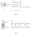
figure 3 shows a diagram which illustrates the steps (from the left) of choosing the therapy, obtaining the various laser emission wavelengths and of distributing the average powers of the various wavelengths, according to the present invention; -
figure 4 shows the step of measuring absorptions according to the body temperature measured during a "pretreatment" during which the various wavelengths are emitted in sequential manner; -
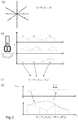
figures 5a-5d show the various steps of the method according to the disclosure, from the Kiviat diagram (a) to pretreatment step (b), for each individual patient or based on common characteristics of a set of potential patients, whereby obtaining absorptions (c); treatment on the basis of the determined parameters (d) with real-time feedback; -
figure 6 shows a flow chart which describes the method infigure 5 ; -
figure 7 shows the detailed flow chart of the pretreatment step; -
figure 8 shows the detailed flow chart of the parameter calculation and treatment step of the method according to the disclosure; -
figure 9 shows a block chart of the apparatus according to the invention; -
figure 10 shows a block and flow diagram which briefly describes the operation of the apparatus according to the invention; -
figure 11 shows a perspective view of the apparatus according to an embodiment of the present invention; -
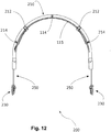
figure 12 shows a front view of the apparatus infigure 11 ; -
figure 13 shows a view from the bottom of the apparatus infigure 12 ; -
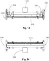
figure 14 shows a view from the top of the apparatus infigure 12 ; and -
figure 15 shows a front view of a different embodiment of the apparatus according to the present invention. - Throughout this description and in the appended claims, it is understood that the word "comprises" can be replaced by the expression "consists of". Furthermore, elements of the embodiments may be extracted from them and used also independently from the other elements and details.
- The illustrated and suggested embodiments may be combined.
- With reference to
figure 1 , the incident irradiation of the laser power p on a non-punctiform surface in the skin/body is broken down into reflected irradiation rp, absorbed irradiation ap, as absorbed by the surface layers, and transmitted radiation tp, as transmitted in the deeper layers of the body. - The absorbed and transmitted radiation depends on the physical properties of the tissue, such as color and composition (e.g. amount of water of the tissue, blood, melanin, and all the tissue chromophores).
- With reference to
figure 2 , according to the disclosure, the method firstly sets on the device which and how many effects are to be obtained from the laser treatment. - With reference to
figure 3 , the physician's choice is processed by means of an algorithm, which transforms the working modes of each laser of the device according to the invention having frequencies λ1, λ2, λ3, λ4 ... λn, respectively. - With reference to
figures 1(b) ,4 ,5(b), 5(c) ,6 ,7 , a "pretreatment" test is performed on the patient, during which the absorptions are measured on the basis of body temperature, by measuring a variation ΔT1, ΔT2, ΔT3, ΔT4, ... ΔTn for the respective wavelengths λ1, λ2, λ3, λ4 ... λn, whereby obtaining the absorption profile of the skin αλ1, αλ2, αλ3, αλ4, ... αλn. - With reference to
figure 1(b) , with regards to the surface portion, α will indicate the general absorption of the skin. The absorbed radiation in the first skin layers is transformed into the temperature increase ΔT in a time Δt which can be measured by the sensor integrated in the laser emission head of the device according to the invention. - Specifically, we have similar definitions for each wavelength. Having predetermined a constant surface power and a short time Δt, the temperature difference ΔT is measured between the start and end of the laser emission at length λ i (ΔTλ
i ), so as to determine an absorption αλ i . - Alternatively and preferably, having predetermined a maximum temperature T max to be reached on the skin surface, such as not to cause pain/burns, the time required Δt to reach such temperature is measured starting from a minimum predetermined temperature, so as to obtain αλ i .
- The coefficient αλ
i indicates the temperature increase of the skin when a laser light of average power p is applied on a non-point-like surface and non-null area (e.g. a unitary surface). αλ i is the inverse of the thermal capacity of the skin, and, since it is strongly dependent on the absorbed wavelength λ I , it will be named "skin absorption" for the sake of simplicity. In both method alternatives above we have:

- The device obtains the body-skin profile on the basis of the ΔT°C detected for the different λ.
- In more detail, with reference to the preceding figures, absorption αλ is measured by measuring the patient's skin temperature. If the instantaneous measured temperature T t is lower than a temperature Tmin, the method continues; otherwise, the laser application position on the skin is changed and the methods starts again.
- The device continuously emits predetermined low power (e.g. 1W) (starting from
wavelength 1 up to n, in any order), and the irradiation continues to temperature Tt<T min. - At this point, a computerized calculation unit calculates the time to reach a second temperature T t = T max. On the basis of the previous formula, αλ is calculated (see formula (1) above).
- The cycle starts again proceeding with the calculation of the absorptions, emitting the successive wavelengths λ.
- Considering a superposition of the effects, the laser head identifies a single temperature difference during the treatment, to be considered as the sum of the temperature contributions of the different wavelengths:


- The αλ
n determine a profile for adjusting the powers (average or peak) during treatment, so as not to exceed a predetermined temperature (fig. 4 ). - After having measured these absorptions, with reference to
figure 8 , the method proceeds with the successive processing and laser treatment steps. - At the start of the treatment, the physician chooses a set of parameters displayed on screen, e.g. represented in the form of a Kiviat diagram. The set of these parameters will be called S and will be described in details below. The power emitted during the treatment will be correlated to the temperature measured by the temperature sensor, therefore, on the basis of the detected temperature, the device will change the power (peak or average), frequency and duty cycle parameters in real-time so as to follow the powers and frequencies deriving from the processing of the profile parameters S chosen at the onset by the physician and limiting the skin surface temperature to a safe maximum temperature.
-
Figure 5d shows a chart of the adaptive spectral power treatment according to the present disclosure, in which the power depends on the parameters described hereto:
figure 2 . - The function Pstot is a method which transforms the parameters chosen by the physician into a power which will be emitted by the device during the treatment. Such method can be based, for example, on the use of look-up tables and interpolation algorithms. Analytical expressions can also be used for the function Pstot, or other optimization algorithms (e.g. statistical), according to cases and conveniences.
- G is a feedback function (
figure 10 ) which modifies the parameters processed by Pstot according to the temperature read by the sensor. - The physician sets the treatment parameters (see
figure 2 ). The calculation unit loads the measured absorptions αλ from a physical memory. - The physician performs the treatment with powers p λ
i for i = 1,...,n for the various wavelengths, in which the total power is
- The skin temperature Tt in the treatment area is measured during the treatment and the power parameters are adapted on the basis of this temperature according to the aforesaid function G. When a preset time limit or a preset maximum irradiated energy (or "limit") is reached, the treatment is concluded (maximum energies or maximum times of the entire treatment are predetermined by persons skilled in the art, e.g. empirically, according to the desired therapy and the body area to be treated).
- Describing the method in more detail, be n the number of wavelengths λ that the device according to the invention can emit.
- P is a set of powers p emitted by the various wavelengths of the device:

- Be γ a step, i.e. the emission of a plurality of laser beams having a wavelength λ1 ,λ2 , ...λn , with respective powers pλ1,pλ2, ... pλn, frequencies fλ1,fλ2, ..., fλn, and duty-cycles δ λ1,δ λ2, ...,δ λn , which are emitted with the respective energies e λ1 ,e λ2 ,...,eλn:


- It is worth noting here that γ may also depend on p λi without δ λi or vice versa because they both have the adjustment of the average power which is the one which contributes to the overheating of the patient as a consequence. In the first case, the duty-cycle may also be kept fixed in therapeutic treatments to a predetermined value.
- Let Γ be a treatment, i.e. a set m of steps γ:

- Without complicating the notation, it is worth noting that for different steps γ 1 , γ2 , ..., γm, the wavelengths will always be the n above, while the other values of the matrix may be different from step to step in general.
- S is a number r of points of the Kiviat diagram (or other equivalent diagram or a different starting diagram but which makes it possible to choose the medical parameters or simply a number of initial parameters set in any manner). These points represent the number of therapeutic effects desired by the physician, wherein each element has a weight s between 0 and 1:


- The device contains a look-up table tab(P) in its memory which links the points S with a set of powers Pi,j. The set of the powers Pi,j of each point and wavelength may be obtained from empirical results which maximize the effect representing j-th branch, or may be initial estimated values which are then adjusted over time.
- The powers of each step of the treatment will be:


- Given a point s j of a Kiviat axis which represents an effect correlated to the power, if we have pmin ij in the zero position and we have pmax ij in the maximum position, the therapy will be adapted to the point pλi chosen by the therapist between (with possible interpolation):


- The exact value in this interval is calculated with a predetermined function, e.g. an interpolation function. This is because the physician in the experimentation step of the therapy determines the effective intervals and then the device decides what exact value to apply alone. This exact value will be called p λi,j(Sj ) ∈ Pi,j.
- The power of each single wavelength which will be calculated as initial total therapy power with multiple wavelengths and multiple selected therapeutic effects, will be a combination of all the effects S:


- The total initial power of the treatment will be the sum of all the points of the matrix tab(P):

tab(P) s1 s2 ... sr λ 1 P1,1 P1,2 P1,r λ2 P2,1 P2,2 P2,r ... λn Pn,1 Pn,2 Pn,r - The device contains a table tab(F) in its memory which links the points S of the Kiviat diagram to a set of frequencies Fi,j. The set Fi,j is obtained from empirical results which maximize the effect representing the j-th axis, or may be initial estimated values, which are then optionally adjusted over time.
- The frequencies (amplitude modulation) of each step of the treatment will be:

- Given a Kiviat branch, which represents an effect correlated to frequency, if we have a measurement of the maximum interval Fi,j in the position zero s and a measurement of the minimum interval Fi,j in the maximum position s, the therapy will be adapted to point f chosen by the therapist, so that it is comprised between (with possible interpolation):


- The exact value in this interval is calculated with a predetermined function, e.g. an interpolation function. This is because the physician in the experimentation step of the therapy determines the effective intervals and then the device decides what exact value to apply alone. This exact value will be called f λi,j(Sj) ∈ Fi,j.
- The modulation frequency of each individual wavelength will be calculated by any statistical function (e.g.: maximum search, minimum search, etc., on the intersection, union etc. of the intervals) which acts on the sets Fi,j :


tab(F) is shown below:tab(F) s1 s2 ... sr λ1 F1,1 F1,2 F1r λ2 F2,1 F2,2 F2,r ... λn Fn,1 Fn,2 Fn,r - The device further contains a table tab(E) in its memory which links the points S of the Kiviat diagram with a set of energies Ei,j. The set Ei,j is obtained from empirical results which maximize the effect representing the branch or may be initial estimated values.
- The energies of each step of the treatment will be:
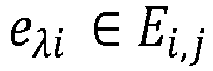

- Given a Kiviat branch, which represents an effect correlated to the energy to be emitted in the treatment, if we have minimum energy emm in the zero position and maximum energy emax in the maximum position, each wavelength must emit an energy eλi , such that:


- The exact value in this interval is calculated with a predetermined function, e.g. an interpolation function. This is because the physician in the experimentation step of the therapy determines the effective intervals and then the device decides what exact value to apply alone. This exact value will be called e λi,j(Sj )∈Ei,j .
- The energy of each single wavelength which will be calculated as the initial total therapy energy with multiple wavelengths and multiple selected therapeutic effects will be a combination of all the effects S:


- tab(E) is shown below:
tab(E) s1 s2 ... sr λ1 E1,1 E1,2 E1,r λ2 E2,1 E2,2 E2,r ... λn En,1 En,2 En,r - The energies can be split into the steps in a homogeneous way or according to a distribution algorithm, which depends on the parameters S.
- More details on the determination of the various steps of the method are provided below:
The method according to the disclosure may use different algorithms. - The first algorithm determines the number of steps of a treatment.
- After the therapist has chosen the parameters S, the treatment Γ is processed as a set m of successive steps γ:

- For each wavelength, there may be multiple different modulation frequencies which make it possible to obtain the effects of the various parameters S. The number of steps M is thus the maximum number of necessary modulation frequencies between all wavelengths. So it is the maximum number of subsets Fλ,j of the table tab(F) to which the frequency fλ belongs:

- The time t of each step will depend on the energy Eλ,j obtained from tab(E).
- It is worth specifying here that instead the powers and/or the duty-cycles will remain preferably the same for each step, so as to not influence the effects given by the modulation frequencies excessively. In all cases, the powers may also be varied provided that the empirical results justify the change. This is also possible because the powers in the table are given as intervals and so there is almost always a margin.
- Since the power varies during the step (see function G which adjusts the total power), the total step time is variable and will be calculated on-the-fly by means of the function G (according to how much the skin is overheated).
- Before treatment, we have an algorithm of:
- a) DETERMINATION of the empirical powers pλ
i of each single step by means of the table tab(P), according to the Kiviat points S chosen by the physician (see above); the total power emitted by the device will be the sum of all pλi for i= 1, ...n; - b) If the various frequency intervals determined for the various λi have non-null intersection, DETERMINATION of the empirical frequencies fλ
i of each single step in the table tab(F), according to the Kiviat points S chosen by the physician (see above); - c) If the various frequency intervals determined for the various λi have null intersection, optional DETERMINATION of the number of steps corresponding to the number of disjoint intervals among all intervals so as to administer the frequencies in succession;
- d) Optional DETERMINATION of empirical energies e λ
i of each single step by means of table tab(E), according to Kiviat points S chosen by the physician; the total energy emitted by the device will be the sum of all eλi for i= 1, ...n (the powers for each step may be the same or different according to possible empirical results or estimates). - During the treatment, we have an algorithm of:
e) FEEDBACK with temperature: i.e. the correction (reduction or increase) of average powers (in sequential or temporary manner) by varying the duty-cycles δλi (or by means of peak powers pλi ); such change is performed on the basis of the absorptions αλi described above, e.g. proportionally thereto, so as to stabilize the temperature Tt read by the sensor in the laser head. - The function G seen above is a correction of the treatment starting power Ps (λi ,Sρ) and may be for example:

- We will see an example with two wavelengths λ1, λ2.
- We will assume that there are 2 effects, so 2 Kiviat axes, called "BIOSTIMULATION", represented by si, "ANALGESIC", represented by S2.
- The user selects:
- S1 = 0.2
- S2 = 0.8
- A table tab(P) is assumed:
tab(P) s1 s2 λ 1 [0.5W, 1W] [0.1W, 2W] λ 2 [0.1W, 0.2W] [1W, 2W] - We will assume that the algorithm which determines the pλi is linear of the type:


- We will assume that the statistic function PS is an arithmetic mean. Therefore, we then have:

- Similarly, we have:


- The power output in instant t=0, is:

- We will assume that T min= 37.5°C, T max= 39.5°C.
- The physician performs the pretreatment in an area of the body at Tt = 38°C. The device indicates to change zone because Tt = 38 °C > Tmin.
- The physician changes area and Tt = 36.5 °C is read. The device starts the pretreatment, emitting a power P= 1W with λ1, and the sensor measures an increment of:


- Similarly, we will assume an increase of 2°C is measured in 20s for λ2:

- It can be inferred that the patient's skin overheats with λ1 faster than λ2.
- We will assume that the function G is a feedback of the integral type. In this case, we have

- We will assume that the function acts on the wavelengths where the effect desired by the physician is the lower of the two. Coefficients K1, K2 will be of the type:

- For example, assuming that the temperature sampling time is 3 seconds, if the temperature sensor measures an increase of 0.9 °C in the first sample and that the system is stable with k1 = 0.05, k2 = 0.1, we have:

- The feedback function G will lower the power of λ1 by 0.68W and λ2 by 0.38 W.
- In output we have:


- We will assume that the "Biostimulation" effect S1 is concentrated on high modulation frequencies (around 1kHz), while the "Analgesic" effect S2 is concentrated on low frequencies (around 10Hz).
- We will assume that the extension of the interval related to λ1 is much greater than the one related to λ2 because λ1 is scarcely influential as the modulation frequency varies, and that the benefits of λ2 are for a restricted interval of frequencies. We will have an empirical table of the type:
tab(F) s1 s2 λ1 Extended High f Extended Low f λ2 Restricted High f Restricted Low f - The following is desired:





- The physician's choices were S1=0.2, S2 = 0.8.
- Assuming that the interval varies in a linear manner, we have:



- Table tab(F) becomes:
tab(F) s1 = 0.2 s2 = 0.8 λ1 [201, 8200]Hz [4, 32]Hz λ2 [920, 1080]Hz [10, 10]Hz - We will assume that the function FS acts on the sets intersection.
- λ2. We have two disjoint intervals both for λ1 and for
- We will assume that the average value is used for each interval:


- A treatment Γ will therefore be performed as a set of 2 steps:



- If the choice had been:
tab(F) s1 = 0 s2 = 0 λ1 [1, 10k]Hz [1, 100]Hz λ2 [900, 1100]Hz [9, 11]Hz - If FS acts on the central/average value of the intersection of the non-disjoint intervals, we have:


- We will assume that little energy λ1 is needed to have the "BIOSTIMULATION" effect and conversely that a lot of energy λ2, is needed for the "ANALGESIC" effect:
tab(E) s1 s2 λ1 [20J,30J] [1J,3J] λ2 [1J,2J] [10,15J] - We will assume that the algorithm which determines the eλ
i is linear of the type:


- It is worth noting that the particular algorithm will be in general decided together with the physician who provides the treatment according to empirical results.
- The total energy emitted by λ1 must be:


- The energies may be distributed in the various steps according to distribution algorithms (in general decided together with the physician who provides the treatment according to empirical results). For example, here we have chosen to subdivide the energies for each step in equal manner:


- Another possible distribution algorithm may be that of associating with each step, each


- With reference to
figure 9 , in an embodiment of the invention, the multi-frequency laser device for skin treatment comprises apower supply unit 104, aCPU 105, alaser module 103 controlled by theCPU 105, adriver 101 which contributes to controlling the (one or more)laser modules 103. - To the
CPU 105 may be connected agraphic screen 106. - The output of the
laser modules 103 is sent by means of respectiveoptical fibers 102 torespective heads 120 for skin application, provided with infrared sensor 121 (or other sensor) for measuring the temperature. - It is worth specifying here that the laser heads 120 do not contain the laser generation part, but only the end part of the optical fibers which depart from the laser module or
modules 103 and possibly other sensors and/or devices which do not relate to laser beam generation. As a result, the laser heads are very light and in practice the method according to the present description moves the end parts of the optical fibers, with great energy savings and reduction of the risk of mechanical interference between the complete laser devices which are usually used in the prior art. - It is worth noting that the head is a
motorized unit 122 controlled by computer (theCPU 105 itself, for example). The laser head receives the laser light from an electro-optical connector oroptic fiber 102. The received light passes through one ormore lenses 123 before reaching the skin. - A
distance sensor 124 may be present in the laser head (distance between head and patient and/or position of the carriage along the arch). - The
CPU 105 is connected to adata connection 125 to thehead 120 to exchange data for the purposes of acquiring the instantaneous temperature and the distance/position. -
Figure 10 shows the feedback produced by theCPU 105. The Kiviat diagram data are acquired by the CPU which uses them to calculate the output power according to the method described above. - Using the pre-calculated skin absorption and the instantaneous skin temperature acquired by the
sensor 121, the CPU calculates the correction function G and adjusts the power and other emission parameters in real time with a feedback cycle. - In this manner, both the patient's safety and the effectiveness of the therapy according to medical indications is ensured, by virtue of an entirely automatic adjustment (which therefore does not require the intervention of a physician during the therapy itself, which can be performed by other staff).
- Figures from 11 to 14 illustrate an apparatus which implements the method referred to above, but which is also independent and may implement other methods. When implementing the method above, one or more laser heads with a temperature sensor are used.
- The
apparatus 200 for laser therapy of apatient 300, firstly comprises at least onearched support 210 which defines an arch, with a firstarch end 217 and a secondarch end 218. The arch may be continuous as inFig. 11(a) or broken as inFig. 11(b) according to constructive convenience. - The apparatus may also comprise a suspension system 230,250 of said at least one
arched support 210. For example, the suspension system comprises moving means, e.g. a wheeled system or a sliding system on guides fixed to the patient's bed 400 (not shown) or other system. Optionally, there may be avertical adjustment system 230 of the arched support. The vertical adjustment system may also comprise an ultrasound sensor (not shown) to calculate the distance of the arch from the specific patient. - Obviously, it comprises at least one
laser generation unit 220 either connected or fixed to said at least onearched support 210. - One or
more guides 215 are fixed along the arch of said at least onearched support 210. - At the end of the aforesaid laser emission, at least one
laser head 212 is connected, by means of sliding connection means, on at least one of said one ormore guides 215, said at least onelaser head 212 having a respective laser emission direction towards the inside of said at least one arched support 210 (see below for further details). - Motorized means are present for moving said at least one laser head slidingly along at least one portion of said at least one of said one or more guides 215. The sliding extension will depend on the type of treatment, in all cases a sliding as wide as possible is preferable in order to be able to reach all the uncovered parts of the body, while the patient is on the
bed 400. - At least one
volumetric scanning sensor 214 is integrally connected to said at least onearched support 210 and is configured to detect a volume occupied by said patient, in use. This is important because the system needs to know where to direct the laser beams and in some cases patient's mass must be calculated. The volumetric scanning system is not a proximity sensor, which works in linear manner along a line, but a system which renders an entire volume, i.e. the three-dimensional shape of the patient on the bed. It may be a suitable camera or other sensor. In an embodiment, the volumetric scanning system comprises a series of TOF (Time Of Light) sensors distributed along the arch of the device. Given a correct distribution of the TOF (Time Of Light) sensors along the arch (practically, they are placed under the arch, e.g. by the side of where the laser fibers slide), the software of the device processes the data read by the sensors and reproduces a 3D scanner, both temporally and spatially. This is used to determine the best possible geometry and accuracy, obtaining the reconstruction of the spatial geometry of the patient's body. The proximity sensor may still be present because it performs an independent function, i.e. it is used during the treatment to ensure a uniform distance of the laser head from the patient. Instead, the volumetric sensor is usually used before the treatment for reconstructing the entire patient's shape and volume to see how deep the tissues to be treated are. Optionally, the volumetric sensor can be used to calculate the patient's volume and then the patient's average density, and then adjust the dose of laser energy to be administered on the basis of the average density of the body. The dose for the area can be calculated according to the body area to be treated. - According to the present description, it is possible and advantageous to calculate the minimum energy emin and the maximum energy emax on each axis of the Kiviat diagram described above and illustrated by correcting the value set by the physician with a coefficient which will be calculated on the basis of the detection of the volumetric sensor. Indeed, it is apparent that if the same energy were given to a hand and a belly, being the surface/volume ratio much higher in the hand, one runs the risk of side effects or a lower treatment effectiveness, respectively. Accordingly, the values for the hand must be lowered and the values for the belly must be raised according to their volume. A different correction is possible for each axis of the Kiviat diagram. The exact coefficients will be determined empirically, by measuring the volumes and the effects obtained on various subjects.
- At least one temperature sensor for detecting, in use, an instantaneous temperature T t of the skin of said
patient 300 under saidarched support 210. Conveniently, an infrared sensor may be used. - Obviously, there is a central processing unit, which in the drawings is incorporated in the
same housing 220 as the laser generator (but can also be placed in a different position), electronically connected to said at least one temperature sensor, to said at least onevolumetric scanning sensor 214 and to said motorized means. A program is installed on thecentral unit 220 and configured to actuate said at least onelaser generation unit 220 and said motorized means, on the basis of predefined data (e.g. therapy to be performed), the temperature detected by said at least one temperature sensor and of the data detected by said at least onevolumetric scanning sensor 214. - There may also be a single guide. There may also be two laser heads 212 (regardless of the number of guides), each connected in sliding manner and moved by said motorized means on half of said single guide (or multiple guides), wherein said at least two laser heads 212 are optionally equipped with position sensors to avoid collisions between them.
- There may be four (or more) laser heads, with the first two first laser heads 212 moved by said motorized means on (substantially) one half of said single guide, and two second laser heads 212 moved by said motorized means on the other (substantially) half of said single guide.
Reference numeral 216 indicates the support for moving the connecting cables between the laser generator and the laser heads. - Referring to
Fig. 15 , the laser emission directions of said at least two laser heads are inclined by an angle α with respect to the perpendicular to the tangent of said arch, wherein α is comprised between 0.1 and 7 sexagesimal degrees, in particular between 2 and 6 degrees, more particularly between 5 and 6 degrees. In this manner, when the laser heads are close together, they all contribute to the substantial irradiation of a single zone on the patient, whereby increasing the total irradiation power, and thus avoiding the need to use very powerful laser generators. - As mentioned above, the suspension system 230,250 consists of two sets of
vertical guides 250 connected to two respectivemotorized wheel devices 230, the two sets of vertical guides being connected to saidfirst end 217 and to saidsecond end 218, respectively, so that saidarched support 210 is adjustable in height with respect to saidwheeled devices 230 by means of respective height adjustment systems (not shown), said motorizedwheeled devices 230 and said respective height adjustment systems being operable by saidcentral processing unit 220 according to said predefined data, the temperature detected by said at least one temperature sensor and of the data detected by said at least onevolumetric scanning sensor 214. - The program installed on said
central processing unit 220 is conveniently configured to actuate said at least onelaser generating unit 220 and said motorized means on the basis of a dose to be supplied to the patient and calculated on the basis of the data detected by said at least onevolumetric scanning sensor 214 and by said at least one temperature sensor and by predetermined information about the area of the patient to be treated. - Finally, a touchscreen interface can be advantageously provided on said arched support for setting a laser therapy plan.
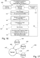
- Referring to
figures 16 and 17 , according to an additional or alternative aspect of the present description, the system provides a system and a method for updating and optimizing the therapeutic parameters. - A plurality of
machines 420 according to the present description form asystem 400 and are connected either individually or in groups to aserver 430 by means ofconnections 430, e.g. Internet connections. - An
optimization algorithm 300 is responsible for updating theinitial parameters 310 of each machine or group of machines. This takes place starting from the initialstandard parameters 310, to which the data related to the patient's mass obtained by said volumetric sensor are added. With all these parameters, the machine performs a therapy in 330. At the end of the therapy, in 350, the device examines the parameters for each effect targeted by therapy. It asks the patient and/or the physician to provide a numerical assessment of the result of each targeted effect in 360 and these assessments are transmitted to the server in 370. A database is increased on the server in this manner by all the machines. In such a manner, at the time of a new therapy in 380, the method queries the database in 390 and the standard parameters are redefined on the basis of the data of all or part of the similar therapies. For example, standard parameters are reset in 395 as average parameters of the similar or identical therapies. The standard parameters may be, for example, energy, irradiance, wavelength and modulation. - Examples of questions asked for assessment are the following:
- Analgesic effect: The device can ask for assessment immediately after the therapy and before the successive treatment.
- Anti-inflammatory effect: The device can ask for assessment immediately after the therapy and before the successive treatment.
- Antimicrobial effect: The device can ask for assessment immediately before the successive treatment only; this is because time is needed for the treatment to become effective.
- Surface biosimulation effect: The device can ask for assessment immediately before the successive treatment only; this is because time is needed for the treatment to become effective.
- The errors of any incorrect assessments provided to devices by therapists are automatically mitigated over time, because the comparison of the parameters of each single device occurs on the average of the parameters of all other devices; consequently, errors will be automatically canceled out over time, therapy after therapy.
- This progressive group self-learning system on global level between the devices, independently and automatically, will transform a static therapy device into an intelligent device, which will increasingly optimize treatments more and more on its own, to approach a performance perfection which would not be achievable manually or with any other software system.
- According to an additional or alternative aspect of the present description, the system in order to accomplish the aforesaid optimization or for other purposes, envisages the use of Artificial Intelligence routine, e.g. by means of Neural Networks or Convolutional Neural Networks, to optimize the treatment parameters autonomously, initially starting from a setting of standard or preset parameters.
- For example, the Artificial Intelligence can optimize the questions for the aforesaid assessments according to the assessments of therapies themselves and/or according to other useful information.
- These data allow the Artificial Intelligence to learn from past experiences of the same machine if similar conditions of the patient occur again.
- The aforesaid database above is on a server, but it could be replicated locally. The artificial intelligence may also be local and/or on the server.
- Importantly, the Artificial Intelligence must use the training data to recognize the best possible treatment (in terms of objective parameters of the therapeutic device, such as for example laser source parameters, irradiance, modulation, energy, wavelengths) for the individual patient on the basis of the intrinsic relations which it can obtain from the data.
- The embodiment with the Artificial Intelligence provided on the single machine has the advantage of providing a complete machine, which needs to access data only.
- In this manner, we have a progressive group self-learning system on global level between devices, independently and without a manual human contribution. The system, in this manner, is no longer operator-dependent and the physicians can optimize their clinical analysis and maximize the success of their care.
- The first laser, L1, is at 660nm and we have:
- laser power: 100mW (only for specifying the laser generator used)
- Irradiance 50mW/cm2
- Fluence 6J/cm2
- Treatment time 120s
- The area of the spot is 2cm2, the diameter of the spot 16mm.
- The second laser, L2, is at 800nm and we have:
- laser power: 1W (only for specifying the laser generator used)
-
Irradiance 200 mW/cm2 - Fluence 6J/cm2
- Treatment time 30s
- The area of the spot is 5 cm2, the diameter of the spot is about 25mm.
- The third laser, L3, is at 970nm and we have:
- laser power: 2.5W (only for specifying the laser generator used)
- Irradiance again 200 mW/cm2
- Fluence 6J/cm2
- Treatment time 30s.
- The area of the spot is about 12.5 cm2, the diameter of the spot is about 40mm.
- By optimizing the therapeutic parameters, it is possible to obtain multiple and different clinical benefits for the patient within the same treatment. All this guarantees maximum safety for the patient, whereby reducing possible risks of iatrogenic damage (possibly caused by the specialist due to an incorrect or inadequate pretreatment assessment which with this patent is no longer required). Moreover, by optimizing many benefits within the same treatment, the therapy times are considerably reduced both in biological terms for the patient and in economic terms for the professional. Obtaining any desired effect is visually represented by the machine in real time, peculiarity which guarantees the correct performance of the required treatment to the professional.
- Hereto, we have described the preferred embodiments and suggested some variants of the present invention, but it is understood that a person skilled in the art can make modifications and changes without departing from the respective scope of protection, as defined by the appended claims.
Claims (17)
- An apparatus (200) for laser therapy of a patient (300), comprising:- at least one arched support (310) which defines an arch, with a first arch end (217) and a second arch end (218);- a suspension system (230,250) of said at least one arched support (210);- at least one laser generation unit (220,103) connected to said at least one arched support (210);- one or more guides (215) fixed along the arch of said at least one arched support (210);- at least one laser head (212,120) separated from said at least one laser generation unit (220,103) and connected to it by means of optical fibers (102), the laser head being slidingly connected, on at least one of said one or more guides (215), said at least one laser head (212,120) having a respective laser emission direction towards the inside of said at least one arched support (210);- motorized means (122,101) for moving said at least one laser head (212,120) slidingly along at least one portion of said at least one of said one or more guides (215) ;- at least one volumetric scanning sensor (214,124) connected integrally to said at least one arched support (210), configured to detect a volume occupied by said patient, in use;- at least one temperature sensor (121) for detecting, in use, an instantaneous temperature Tt of the skin of said patient under said arched support (210); and- a central processing unit (220,105) electronically connected to said at least one temperature sensor, to said at least one volumetric scanning sensor (214,124) and to said motorized means, a program being installed on said central processing unit (220,105) which is configured to actuate and/or adjust said at least one laser generation unit (220,103) and said motorized means, on the basis of predetermined data, of the temperature detected by said at least one temperature sensor and of data detected by said at least one volumetric scanning sensor (214,124),Wherein:- said at least one laser generation unit (220,103) is configured to generate a number n, n being a non-null positive integer, of laser beams with respective frequencies λ 1 , λ 2 ,... λ n to be sent to each of said at least one laser head (212,120);and- said program comprises the following modules:wherein said module C interrupts the generation of the laser beams when a preset time limit or a preset maximum radiated energy limit is reached.- a first module A configured to acquire a set of user parameters S = {S 1, S 2 ,..., S r} with 0 ≤ Sj ≤ 1 and j = 1...r, wherein r is a positive integer greater than 1;- a second module B configured to acquire an absorption coefficient αλi of the patient's skin with respect to the wavelength λ i , for each i = 1...n, for example by a preliminary assessment step or from a database;- a third module C configured to control said laser generation unit (22,103) to send said laser beams to said at least one laser head (212,120), after execution of said second module B, so as to generate the laser beams of respective wavelength λ 1 , λ2, ... λn with respective powers p λi for i=1,...,n for the various wavelengths and for a total power of all the laser beams given by the sum of:- a first fixed contribution corresponding to a value obtained on the basis of all the wavelengths λ1,λ2,... λ n and of the parameters S = {S 1 ,S 2 , ...,Sr };- a second feedback instantaneous corrective contribution, as obtained on the basis of the time t elapsed since the start of the generation of the laser beams by module C, of all the coefficients α λ1, a λ2..., α λn of the temperature difference ΔT between a preset nominal temperature and the temperature T detected by said at least one temperature sensor (121) as well as of the parameters S = {S 1 ,S 2, ..., Sr};
- An apparatus according to claim 1, wherein there is a single guide and there are at least two laser heads (212,120) each slidingly connected and moved by said motorized means (122,101) on a half of said single guide only, wherein said at least two laser heads (212,120) are optionally equipped with position sensors (124) to prevent collisions one against the other.
- An apparatus according to claim 2, wherein there are four laser heads (212,120), with two first laser heads (212,120) moved by said motorized means on one half of said single guide, and two second laser heads (212,120) moved by said motorized means on the other half of said single guide.
- An apparatus according to any one of claims from 2 to 4, wherein the respective laser emission directions of said at least two laser heads are inclined by an angle α with respect to the perpendicular to the tangent to said arch, wherein α is between 0.1 and 7 sexagesimal degrees.
- An apparatus according to any one of claims from 1 to 4, wherein said suspension system (230,250) is constituted by two sets of vertical guides (250) connected to two respective wheeled motorized devices (230), the two sets of vertical guides being connected respectively to said first arch end (217) and said second arch end (218) so that said arched support (210) is adjustable in height with respect to said wheeled devices (230) by means of respective height adjustment systems, said wheeled motorized devices (230) and said respective height adjustment systems being operable by said central processing unit (220) on the basis of said predetermined data, of the temperature detected by said at least one temperature sensor and of data detected by said at least one volumetric scanning sensor (214).
- An apparatus according to any one of claims from 1 to 5, wherein said program installed on said central processing unit (220,105) is configured to actuate said at least one laser generation unit (220,103) and said motorized means on the basis of a dose to be supplied to the patient calculated on the basis of the data detected by said at least one volumetric scanning sensor (214,124) and by said at least one temperature sensor and by predetermined information about the area of the patient to be treated.
- An apparatus according to any one of claims 1 to 6, wherein said module B comprises the following sub-modules:- a first sub-module configured to control said at least one laser generation unit (220,103) to send said laser beams to a laser beam application unit, so that, during respective subsequent time intervals Bt
i with i = 1 ... n the laser beams of respective wavelength λ 1 , λ 2 ,...λn each with average power p are respectively and successively generated;- a second sub-module configured to detect, during each time interval Bti of predetermined value, the temperature difference ΔT between a start temperature Tmin and an end temperature T max of the time interval Bti, as measured by said temperature sensor (121), or to set a predetermined temperature difference ΔT and take as the value of Bti the time taken to pass from Tmin to T max as measured by said temperature sensor (121); and- a third sub-module configured to calculate, on the basis of the values Bti and ΔT as determined by the second sub-module, an absorption coefficient αλi of the patient's skin with respect to the wavelength λ i , for all i = 1... n. - An apparatus according to claim 7, wherein said absorption coefficient is calculated by said third sub-module according to the formula:

i and ΔTλi is the value of ΔT as determined for each wavelength λ i , with i = 1...n. - An apparatus according to claim 7 or 8, wherein said second sub-module, if said temperature sensor (221,121) preliminarily detects a temperature Tt lower than Tmin , generates said laser beams until the temperature Tt = Tmin is reached and the time interval Bti begins thereafter.
- An apparatus according to any one of claims 1 to 9, wherein it further comprises a physical internal memory or connection means to a remote physical memory, a look-up table tab(P) which provides a power value or interval Pi,j for each parameter Sj and each wavelength λ i being stored on said internal physical memory or in said remote physical memory, said power value or interval Pi,j being for example obtained in advance from empirical results or from initial estimates, whereas if Pi,j are power intervals we will have:

- An apparatus according to any one of claims 1 to 10, wherein said laser beams have respectively an energy e λ
i for i = 1,...,n, and wherein an internal physical memory or connection means to a remote physical memory are further comprised, a look-up table tab(E) which provides an energy value or interval Ei,j for each parameter Sj and for each wavelength λ i being stored on said internal physical memory or in said remote physical memory, said value or energy interval Ei,j being for example obtained in advance by empirical results or from initial estimates, whereas if Ei,j are energy intervals we will have:
- An apparatus according to claim 11, wherein e mini,j and e maxi,j are corrected on the basis of the information detected by the volumetric sensor, e.g. on the basis of the surface-to-volume ratio of the specified body region to be subjected to laser therapy treatment.
- An apparatus according to any one of claims 1 to 12, wherein:- said laser beams have a modulation frequency fλ i, for i = 1, ..., n respectively and wherein an internal physical memory or means for connection to a remote physical memory is further comprised, a look-up table tab(F) which provides a modulation frequency value or interval Fi,j for each parameter Sj and each wavelength λ i being stored on said internal physical memory or in said remote physical memory, said value or modulation frequency interval Fi,j being for example obtained in advance from empirical results or from initial estimates, whereas if Fi,j are modulation frequency intervals we will have:
 - the module C subdivides said laser beam generation into a number m of successive generations, wherein:∘ m is the maximum number of disjoint subsets which are determined by the superposition of the sets on each row of the table tab(F);∘ for the respective m successive generations, respective modulation frequencies fλi calculated on the basis of a disjoint set or a non-null set as obtained in said superposition will result;∘ the powers p λi are the same or different for the m successive generations; and∘ said maximum energy or said time limit is subdivided over the m successive generations in either equal or different parts.
 - An apparatus according to any one of claims from 1 to 13, wherein, if the measured instantaneous temperature is higher than a threshold temperature, said at least one central processing unit adjusts the power of said laser beams so as to remain below such threshold temperature, said central processing unit (220,103) sending an alarm to an alarm peripheral device.
- An apparatus according to any one of claims from 1 to 14, wherein said parameters S= {S 1, S 2 ,...,S r} are acquired by a graphic interface on which the coordinates of a Kiviat diagram are entered.
- An apparatus according to one or more of the claims from 1 to 15, wherein it comprises:- a module which includes an optimization or learning program;- a connection to a central server on a telecommunications network;wherein the optimization or learning program is configured and adapted to:- receive therapeutic treatment data sets from said central server performed by laser therapy apparatus of the same type as said apparatus for laser therapy;- provide the setup data of the treatment apparatus on a specific patient, on the basis of said therapeutic treatment data sets and of parameters from sensors installed in said apparatus for laser therapy and related to said specific patient.
- An apparatus according to claim 16, wherein said optimization or learning program comprises artificial intelligence routines, able to:- be trained using said data set; and- provide the setup data of the treatment apparatus on a specific patient, on the basis of setup parameters calculated using said data sets and of parameters from sensors installed in said laser therapy device and related to said specific patient.
Priority Applications (1)
| Application Number | Priority Date | Filing Date | Title |
|---|---|---|---|
| PL18735405T PL3634575T3 (en) | 2017-06-08 | 2018-06-07 | Apparatus for scanning laser therapy |
Applications Claiming Priority (2)
| Application Number | Priority Date | Filing Date | Title |
|---|---|---|---|
| IT102017000062592A IT201700062592A1 (en) | 2017-06-08 | 2017-06-08 | Apparatus for scanning laser therapy. |
| PCT/IB2018/054097 WO2018225000A1 (en) | 2017-06-08 | 2018-06-07 | Apparatus for scanning laser therapy |
Publications (2)
| Publication Number | Publication Date |
|---|---|
| EP3634575A1 EP3634575A1 (en) | 2020-04-15 |
| EP3634575B1 true EP3634575B1 (en) | 2021-03-31 |
Family
ID=60294158
Family Applications (1)
| Application Number | Title | Priority Date | Filing Date |
|---|---|---|---|
| EP18735405.5A Active EP3634575B1 (en) | 2017-06-08 | 2018-06-07 | Apparatus for scanning laser therapy |
Country Status (6)
| Country | Link |
|---|---|
| US (1) | US11273322B2 (en) |
| EP (1) | EP3634575B1 (en) |
| ES (1) | ES2879927T3 (en) |
| IT (1) | IT201700062592A1 (en) |
| PL (1) | PL3634575T3 (en) |
| WO (1) | WO2018225000A1 (en) |
Families Citing this family (20)
| Publication number | Priority date | Publication date | Assignee | Title |
|---|---|---|---|---|
| EP4324577A1 (en) | 2015-12-16 | 2024-02-21 | 6K Inc. | Method of producing spheroidal dehydrogenated titanium alloy particles |
| US10987735B2 (en) | 2015-12-16 | 2021-04-27 | 6K Inc. | Spheroidal titanium metallic powders with custom microstructures |
| WO2019246257A1 (en) | 2018-06-19 | 2019-12-26 | Amastan Technologies Inc. | Process for producing spheroidized powder from feedstock materials |
| CN114007985A (en) | 2019-04-30 | 2022-02-01 | 6K有限公司 | Lithium Lanthanum Zirconium Oxide (LLZO) powder |
| US11311938B2 (en) | 2019-04-30 | 2022-04-26 | 6K Inc. | Mechanically alloyed powder feedstock |
| CN110302049A (en) * | 2019-07-12 | 2019-10-08 | 李卫 | A kind of ring type shock wave treatment instrument |
| EP3890827B1 (en) * | 2019-10-30 | 2023-08-16 | Fieldpoint (Cyprus) Limited | Therapeutic irradiation device |
| ES2994209T3 (en) | 2019-11-18 | 2025-01-20 | 6K Inc | Unique feedstocks for spherical powders and methods of manufacturing |
| US11590568B2 (en) | 2019-12-19 | 2023-02-28 | 6K Inc. | Process for producing spheroidized powder from feedstock materials |
| AU2021237872A1 (en) * | 2020-03-17 | 2022-11-03 | Lumenis Be Ltd | Method and system for determining an optimal set of operating parameters for an aesthetic skin treatment unit |
| KR20230029836A (en) | 2020-06-25 | 2023-03-03 | 6케이 인크. | Microcomposite alloy structure |
| KR102811425B1 (en) | 2020-09-24 | 2025-05-26 | 6케이 인크. | Systems, devices and methods for initiating plasma |
| EP4237174A1 (en) | 2020-10-30 | 2023-09-06 | 6K Inc. | Systems and methods for synthesis of spheroidized metal powders |
| CA3202171A1 (en) * | 2020-12-31 | 2022-07-07 | Andrey GANDMAN | Method and system for real time monitoring of cosmetic laser aesthetic skin treatment procedures |
| EP4275239A4 (en) | 2021-01-11 | 2024-12-18 | 6K Inc. | METHODS AND SYSTEMS FOR RECOVERY OF LI-ION CATHODE MATERIALS USING MICROWAVE PLASMA PROCESSING |
| JP2024515034A (en) | 2021-03-31 | 2024-04-04 | シックスケー インコーポレイテッド | Systems and methods for additive manufacturing of metal nitride ceramics |
| WO2023229928A1 (en) | 2022-05-23 | 2023-11-30 | 6K Inc. | Microwave plasma apparatus and methods for processing materials using an interior liner |
| US12040162B2 (en) | 2022-06-09 | 2024-07-16 | 6K Inc. | Plasma apparatus and methods for processing feed material utilizing an upstream swirl module and composite gas flows |
| WO2024044498A1 (en) | 2022-08-25 | 2024-02-29 | 6K Inc. | Plasma apparatus and methods for processing feed material utilizing a powder ingress preventor (pip) |
| US12195338B2 (en) | 2022-12-15 | 2025-01-14 | 6K Inc. | Systems, methods, and device for pyrolysis of methane in a microwave plasma for hydrogen and structured carbon powder production |
Family Cites Families (6)
| Publication number | Priority date | Publication date | Assignee | Title |
|---|---|---|---|---|
| DE69940738D1 (en) * | 1998-07-09 | 2009-05-28 | Curelight Medical Ltd | DEVICE AND METHOD FOR EFFICIENT HIGHERGETIC PHOTODYNAMIC THERAPY OF ACNE VULGARIS AND SEBORRHOE |
| JP2002000745A (en) * | 2000-06-16 | 2002-01-08 | Nidek Co Ltd | Laser therapeutic device |
| US8439959B2 (en) * | 2004-10-29 | 2013-05-14 | Erchonia Corporation | Full-body laser scanner and method of mapping and contouring the body |
| DE602004026050D1 (en) * | 2003-05-05 | 2010-04-29 | Trion Swiss Ltd | LASER DEVICE FOR HEAT TREATMENT |
| CN102470012B (en) * | 2009-07-20 | 2015-03-11 | 皇家飞利浦电子股份有限公司 | Light application apparatus for applying light to an object |
| RU2017128027A (en) | 2015-06-15 | 2019-02-08 | Хаим АМИР | SYSTEMS AND METHODS FOR ADAPTIVE SKIN TREATMENT |
-
2017
- 2017-06-08 IT IT102017000062592A patent/IT201700062592A1/en unknown
-
2018
- 2018-06-07 ES ES18735405T patent/ES2879927T3/en active Active
- 2018-06-07 PL PL18735405T patent/PL3634575T3/en unknown
- 2018-06-07 WO PCT/IB2018/054097 patent/WO2018225000A1/en not_active Ceased
- 2018-06-07 EP EP18735405.5A patent/EP3634575B1/en active Active
- 2018-06-07 US US16/620,346 patent/US11273322B2/en not_active Expired - Fee Related
Non-Patent Citations (1)
| Title |
|---|
| None * |
Also Published As
| Publication number | Publication date |
|---|---|
| EP3634575A1 (en) | 2020-04-15 |
| US11273322B2 (en) | 2022-03-15 |
| US20200179714A1 (en) | 2020-06-11 |
| PL3634575T3 (en) | 2021-10-18 |
| ES2879927T3 (en) | 2021-11-23 |
| IT201700062592A1 (en) | 2018-12-08 |
| WO2018225000A1 (en) | 2018-12-13 |
Similar Documents
| Publication | Publication Date | Title |
|---|---|---|
| US11273322B2 (en) | Apparatus for scanning laser therapy | |
| Li et al. | Overview and recommendations for prospective multi-institutional spatially fractionated radiation therapy clinical trials | |
| US8287524B2 (en) | Apparatus and method for performing radiation energy treatments | |
| Enwemeka | Intricacies of dose in laser phototherapy for tissue repair and pain relief | |
| CN108992243B (en) | Cornea treatment device based on improved solution dripping absorption device | |
| US20130041309A1 (en) | Apparatus and method for performing radiation energy treatments | |
| JP2010516334A (en) | Fiber optic phototherapy equipment | |
| US10258506B2 (en) | Laser therapy system for noninvasive correction of the refractive system of the eye | |
| US20110172746A1 (en) | High Level Laser Therapy Apparatus and Methods | |
| US7160287B1 (en) | Apparatus and method for performing radiation energy treatments | |
| KR101607303B1 (en) | afety distance display device for removable radiotherapy apparatus | |
| US20230145284A1 (en) | Apparatus for treatment of the retina by radiation | |
| US20250332437A1 (en) | Method and system for irradiating a region of the skin of a subject | |
| Michalec et al. | Proton radiotherapy facility for ocular tumors at the IFJ PAN in Kraków Poland | |
| KR20220037933A (en) | Fungal infections treating device | |
| KR20180119802A (en) | laser treatment adaptor feedback system | |
| US10869781B2 (en) | Ophthalmic treatment apparatus and method for controlling same | |
| CN120132217B (en) | A photoelectric integrated physiotherapy system | |
| KR20120137793A (en) | Laser moxibustion therapy and apparatus using the same based on modeling of patient | |
| KR100611526B1 (en) | Skin light irradiator for automatic temperature control and optimum output control of skin contact surface | |
| AU2024328186A1 (en) | Multi-array of sensors to tailor a photobiomodulation dose | |
| KR101849942B1 (en) | Animal model to obtain information about treatment of voiding dysfunction using optogenetics | |
| Reitz et al. | Comparison of the KonRad IMRT and XiO treatment planning systems | |
| CN116133722A (en) | light irradiation device | |
| Savelieva et al. | Method of in situ assessment of optical properties of biological tissues for personalized planning of laser-induced therapy |
Legal Events
| Date | Code | Title | Description |
|---|---|---|---|
| STAA | Information on the status of an ep patent application or granted ep patent |
Free format text: STATUS: UNKNOWN |
|
| STAA | Information on the status of an ep patent application or granted ep patent |
Free format text: STATUS: THE INTERNATIONAL PUBLICATION HAS BEEN MADE |
|
| PUAI | Public reference made under article 153(3) epc to a published international application that has entered the european phase |
Free format text: ORIGINAL CODE: 0009012 |
|
| STAA | Information on the status of an ep patent application or granted ep patent |
Free format text: STATUS: REQUEST FOR EXAMINATION WAS MADE |
|
| 17P | Request for examination filed |
Effective date: 20191127 |
|
| AK | Designated contracting states |
Kind code of ref document: A1 Designated state(s): AL AT BE BG CH CY CZ DE DK EE ES FI FR GB GR HR HU IE IS IT LI LT LU LV MC MK MT NL NO PL PT RO RS SE SI SK SM TR |
|
| AX | Request for extension of the european patent |
Extension state: BA ME |
|
| DAV | Request for validation of the european patent (deleted) | ||
| DAX | Request for extension of the european patent (deleted) | ||
| GRAP | Despatch of communication of intention to grant a patent |
Free format text: ORIGINAL CODE: EPIDOSNIGR1 |
|
| STAA | Information on the status of an ep patent application or granted ep patent |
Free format text: STATUS: GRANT OF PATENT IS INTENDED |
|
| INTG | Intention to grant announced |
Effective date: 20201120 |
|
| RIN1 | Information on inventor provided before grant (corrected) |
Inventor name: ZANATA, ANDREA Inventor name: ZANATA, MAURO Inventor name: ZANATA, ENRICO Inventor name: ZANATA, FRANCESCO |
|
| GRAS | Grant fee paid |
Free format text: ORIGINAL CODE: EPIDOSNIGR3 |
|
| GRAA | (expected) grant |
Free format text: ORIGINAL CODE: 0009210 |
|
| STAA | Information on the status of an ep patent application or granted ep patent |
Free format text: STATUS: THE PATENT HAS BEEN GRANTED |
|
| AK | Designated contracting states |
Kind code of ref document: B1 Designated state(s): AL AT BE BG CH CY CZ DE DK EE ES FI FR GB GR HR HU IE IS IT LI LT LU LV MC MK MT NL NO PL PT RO RS SE SI SK SM TR |
|
| REG | Reference to a national code |
Ref country code: GB Ref legal event code: FG4D Ref country code: CH Ref legal event code: EP |
|
| REG | Reference to a national code |
Ref country code: AT Ref legal event code: REF Ref document number: 1376256 Country of ref document: AT Kind code of ref document: T Effective date: 20210415 |
|
| REG | Reference to a national code |
Ref country code: DE Ref legal event code: R096 Ref document number: 602018014827 Country of ref document: DE |
|
| REG | Reference to a national code |
Ref country code: IE Ref legal event code: FG4D |
|
| REG | Reference to a national code |
Ref country code: LT Ref legal event code: MG9D |
|
| PG25 | Lapsed in a contracting state [announced via postgrant information from national office to epo] |
Ref country code: FI Free format text: LAPSE BECAUSE OF FAILURE TO SUBMIT A TRANSLATION OF THE DESCRIPTION OR TO PAY THE FEE WITHIN THE PRESCRIBED TIME-LIMIT Effective date: 20210331 Ref country code: HR Free format text: LAPSE BECAUSE OF FAILURE TO SUBMIT A TRANSLATION OF THE DESCRIPTION OR TO PAY THE FEE WITHIN THE PRESCRIBED TIME-LIMIT Effective date: 20210331 Ref country code: BG Free format text: LAPSE BECAUSE OF FAILURE TO SUBMIT A TRANSLATION OF THE DESCRIPTION OR TO PAY THE FEE WITHIN THE PRESCRIBED TIME-LIMIT Effective date: 20210630 Ref country code: NO Free format text: LAPSE BECAUSE OF FAILURE TO SUBMIT A TRANSLATION OF THE DESCRIPTION OR TO PAY THE FEE WITHIN THE PRESCRIBED TIME-LIMIT Effective date: 20210630 |
|
| PG25 | Lapsed in a contracting state [announced via postgrant information from national office to epo] |
Ref country code: LV Free format text: LAPSE BECAUSE OF FAILURE TO SUBMIT A TRANSLATION OF THE DESCRIPTION OR TO PAY THE FEE WITHIN THE PRESCRIBED TIME-LIMIT Effective date: 20210331 Ref country code: RS Free format text: LAPSE BECAUSE OF FAILURE TO SUBMIT A TRANSLATION OF THE DESCRIPTION OR TO PAY THE FEE WITHIN THE PRESCRIBED TIME-LIMIT Effective date: 20210331 Ref country code: SE Free format text: LAPSE BECAUSE OF FAILURE TO SUBMIT A TRANSLATION OF THE DESCRIPTION OR TO PAY THE FEE WITHIN THE PRESCRIBED TIME-LIMIT Effective date: 20210331 |
|
| REG | Reference to a national code |
Ref country code: NL Ref legal event code: MP Effective date: 20210331 |
|
| REG | Reference to a national code |
Ref country code: AT Ref legal event code: MK05 Ref document number: 1376256 Country of ref document: AT Kind code of ref document: T Effective date: 20210331 |
|
| PG25 | Lapsed in a contracting state [announced via postgrant information from national office to epo] |
Ref country code: AT Free format text: LAPSE BECAUSE OF FAILURE TO SUBMIT A TRANSLATION OF THE DESCRIPTION OR TO PAY THE FEE WITHIN THE PRESCRIBED TIME-LIMIT Effective date: 20210331 Ref country code: SM Free format text: LAPSE BECAUSE OF FAILURE TO SUBMIT A TRANSLATION OF THE DESCRIPTION OR TO PAY THE FEE WITHIN THE PRESCRIBED TIME-LIMIT Effective date: 20210331 Ref country code: NL Free format text: LAPSE BECAUSE OF FAILURE TO SUBMIT A TRANSLATION OF THE DESCRIPTION OR TO PAY THE FEE WITHIN THE PRESCRIBED TIME-LIMIT Effective date: 20210331 Ref country code: LT Free format text: LAPSE BECAUSE OF FAILURE TO SUBMIT A TRANSLATION OF THE DESCRIPTION OR TO PAY THE FEE WITHIN THE PRESCRIBED TIME-LIMIT Effective date: 20210331 Ref country code: CZ Free format text: LAPSE BECAUSE OF FAILURE TO SUBMIT A TRANSLATION OF THE DESCRIPTION OR TO PAY THE FEE WITHIN THE PRESCRIBED TIME-LIMIT Effective date: 20210331 Ref country code: EE Free format text: LAPSE BECAUSE OF FAILURE TO SUBMIT A TRANSLATION OF THE DESCRIPTION OR TO PAY THE FEE WITHIN THE PRESCRIBED TIME-LIMIT Effective date: 20210331 |
|
| REG | Reference to a national code |
Ref country code: ES Ref legal event code: FG2A Ref document number: 2879927 Country of ref document: ES Kind code of ref document: T3 Effective date: 20211123 |
|
| PG25 | Lapsed in a contracting state [announced via postgrant information from national office to epo] |
Ref country code: SK Free format text: LAPSE BECAUSE OF FAILURE TO SUBMIT A TRANSLATION OF THE DESCRIPTION OR TO PAY THE FEE WITHIN THE PRESCRIBED TIME-LIMIT Effective date: 20210331 Ref country code: PT Free format text: LAPSE BECAUSE OF FAILURE TO SUBMIT A TRANSLATION OF THE DESCRIPTION OR TO PAY THE FEE WITHIN THE PRESCRIBED TIME-LIMIT Effective date: 20210802 Ref country code: RO Free format text: LAPSE BECAUSE OF FAILURE TO SUBMIT A TRANSLATION OF THE DESCRIPTION OR TO PAY THE FEE WITHIN THE PRESCRIBED TIME-LIMIT Effective date: 20210331 Ref country code: IS Free format text: LAPSE BECAUSE OF FAILURE TO SUBMIT A TRANSLATION OF THE DESCRIPTION OR TO PAY THE FEE WITHIN THE PRESCRIBED TIME-LIMIT Effective date: 20210731 |
|
| REG | Reference to a national code |
Ref country code: DE Ref legal event code: R097 Ref document number: 602018014827 Country of ref document: DE |
|
| PG25 | Lapsed in a contracting state [announced via postgrant information from national office to epo] |
Ref country code: MC Free format text: LAPSE BECAUSE OF FAILURE TO SUBMIT A TRANSLATION OF THE DESCRIPTION OR TO PAY THE FEE WITHIN THE PRESCRIBED TIME-LIMIT Effective date: 20210331 Ref country code: DK Free format text: LAPSE BECAUSE OF FAILURE TO SUBMIT A TRANSLATION OF THE DESCRIPTION OR TO PAY THE FEE WITHIN THE PRESCRIBED TIME-LIMIT Effective date: 20210331 Ref country code: AL Free format text: LAPSE BECAUSE OF FAILURE TO SUBMIT A TRANSLATION OF THE DESCRIPTION OR TO PAY THE FEE WITHIN THE PRESCRIBED TIME-LIMIT Effective date: 20210331 |
|
| PLBE | No opposition filed within time limit |
Free format text: ORIGINAL CODE: 0009261 |
|
| STAA | Information on the status of an ep patent application or granted ep patent |
Free format text: STATUS: NO OPPOSITION FILED WITHIN TIME LIMIT |
|
| 26N | No opposition filed |
Effective date: 20220104 |
|
| REG | Reference to a national code |
Ref country code: BE Ref legal event code: MM Effective date: 20210630 |
|
| PG25 | Lapsed in a contracting state [announced via postgrant information from national office to epo] |
Ref country code: LU Free format text: LAPSE BECAUSE OF NON-PAYMENT OF DUE FEES Effective date: 20210607 |
|
| PG25 | Lapsed in a contracting state [announced via postgrant information from national office to epo] |
Ref country code: IE Free format text: LAPSE BECAUSE OF NON-PAYMENT OF DUE FEES Effective date: 20210607 |
|
| PG25 | Lapsed in a contracting state [announced via postgrant information from national office to epo] |
Ref country code: IS Free format text: LAPSE BECAUSE OF FAILURE TO SUBMIT A TRANSLATION OF THE DESCRIPTION OR TO PAY THE FEE WITHIN THE PRESCRIBED TIME-LIMIT Effective date: 20210731 |
|
| PG25 | Lapsed in a contracting state [announced via postgrant information from national office to epo] |
Ref country code: IT Free format text: LAPSE BECAUSE OF FAILURE TO SUBMIT A TRANSLATION OF THE DESCRIPTION OR TO PAY THE FEE WITHIN THE PRESCRIBED TIME-LIMIT Effective date: 20210331 Ref country code: BE Free format text: LAPSE BECAUSE OF NON-PAYMENT OF DUE FEES Effective date: 20210630 |
|
| PGFP | Annual fee paid to national office [announced via postgrant information from national office to epo] |
Ref country code: GB Payment date: 20220627 Year of fee payment: 5 Ref country code: DE Payment date: 20220620 Year of fee payment: 5 |
|
| PGFP | Annual fee paid to national office [announced via postgrant information from national office to epo] |
Ref country code: PL Payment date: 20220601 Year of fee payment: 5 |
|
| PGFP | Annual fee paid to national office [announced via postgrant information from national office to epo] |
Ref country code: FR Payment date: 20220627 Year of fee payment: 5 |
|
| PGFP | Annual fee paid to national office [announced via postgrant information from national office to epo] |
Ref country code: ES Payment date: 20220701 Year of fee payment: 5 |
|
| PGFP | Annual fee paid to national office [announced via postgrant information from national office to epo] |
Ref country code: CH Payment date: 20220630 Year of fee payment: 5 |
|
| PG25 | Lapsed in a contracting state [announced via postgrant information from national office to epo] |
Ref country code: CY Free format text: LAPSE BECAUSE OF FAILURE TO SUBMIT A TRANSLATION OF THE DESCRIPTION OR TO PAY THE FEE WITHIN THE PRESCRIBED TIME-LIMIT Effective date: 20210331 |
|
| PG25 | Lapsed in a contracting state [announced via postgrant information from national office to epo] |
Ref country code: HU Free format text: LAPSE BECAUSE OF FAILURE TO SUBMIT A TRANSLATION OF THE DESCRIPTION OR TO PAY THE FEE WITHIN THE PRESCRIBED TIME-LIMIT; INVALID AB INITIO Effective date: 20180607 Ref country code: GR Free format text: LAPSE BECAUSE OF FAILURE TO SUBMIT A TRANSLATION OF THE DESCRIPTION OR TO PAY THE FEE WITHIN THE PRESCRIBED TIME-LIMIT Effective date: 20210331 |
|
| REG | Reference to a national code |
Ref country code: DE Ref legal event code: R119 Ref document number: 602018014827 Country of ref document: DE |
|
| REG | Reference to a national code |
Ref country code: CH Ref legal event code: PL |
|
| GBPC | Gb: european patent ceased through non-payment of renewal fee |
Effective date: 20230607 |
|
| PG25 | Lapsed in a contracting state [announced via postgrant information from national office to epo] |
Ref country code: MK Free format text: LAPSE BECAUSE OF FAILURE TO SUBMIT A TRANSLATION OF THE DESCRIPTION OR TO PAY THE FEE WITHIN THE PRESCRIBED TIME-LIMIT Effective date: 20210331 Ref country code: DE Free format text: LAPSE BECAUSE OF NON-PAYMENT OF DUE FEES Effective date: 20240103 Ref country code: GB Free format text: LAPSE BECAUSE OF NON-PAYMENT OF DUE FEES Effective date: 20230607 Ref country code: CH Free format text: LAPSE BECAUSE OF NON-PAYMENT OF DUE FEES Effective date: 20230630 |
|
| PG25 | Lapsed in a contracting state [announced via postgrant information from national office to epo] |
Ref country code: FR Free format text: LAPSE BECAUSE OF NON-PAYMENT OF DUE FEES Effective date: 20230630 |
|
| REG | Reference to a national code |
Ref country code: ES Ref legal event code: FD2A Effective date: 20240729 |
|
| PG25 | Lapsed in a contracting state [announced via postgrant information from national office to epo] |
Ref country code: MT Free format text: LAPSE BECAUSE OF FAILURE TO SUBMIT A TRANSLATION OF THE DESCRIPTION OR TO PAY THE FEE WITHIN THE PRESCRIBED TIME-LIMIT Effective date: 20210331 |
|
| PG25 | Lapsed in a contracting state [announced via postgrant information from national office to epo] |
Ref country code: ES Free format text: LAPSE BECAUSE OF NON-PAYMENT OF DUE FEES Effective date: 20230608 |
|
| PG25 | Lapsed in a contracting state [announced via postgrant information from national office to epo] |
Ref country code: ES Free format text: LAPSE BECAUSE OF NON-PAYMENT OF DUE FEES Effective date: 20230608 |
|
| PG25 | Lapsed in a contracting state [announced via postgrant information from national office to epo] |
Ref country code: PL Free format text: LAPSE BECAUSE OF NON-PAYMENT OF DUE FEES Effective date: 20230607 |
|
| PG25 | Lapsed in a contracting state [announced via postgrant information from national office to epo] |
Ref country code: PL Free format text: LAPSE BECAUSE OF NON-PAYMENT OF DUE FEES Effective date: 20230607 |
|
| PG25 | Lapsed in a contracting state [announced via postgrant information from national office to epo] |
Ref country code: TR Free format text: LAPSE BECAUSE OF FAILURE TO SUBMIT A TRANSLATION OF THE DESCRIPTION OR TO PAY THE FEE WITHIN THE PRESCRIBED TIME-LIMIT Effective date: 20210331 |