EP3634307B1 - Method for corneal transplants - Google Patents
Method for corneal transplants Download PDFInfo
- Publication number
- EP3634307B1 EP3634307B1 EP18813963.8A EP18813963A EP3634307B1 EP 3634307 B1 EP3634307 B1 EP 3634307B1 EP 18813963 A EP18813963 A EP 18813963A EP 3634307 B1 EP3634307 B1 EP 3634307B1
- Authority
- EP
- European Patent Office
- Prior art keywords
- supporting structure
- channel
- corneal tissue
- donor
- corneal
- Prior art date
- Legal status (The legal status is an assumption and is not a legal conclusion. Google has not performed a legal analysis and makes no representation as to the accuracy of the status listed.)
- Active
Links
Images

Classifications
-
- A—HUMAN NECESSITIES
- A61—MEDICAL OR VETERINARY SCIENCE; HYGIENE
- A61F—FILTERS IMPLANTABLE INTO BLOOD VESSELS; PROSTHESES; DEVICES PROVIDING PATENCY TO, OR PREVENTING COLLAPSING OF, TUBULAR STRUCTURES OF THE BODY, e.g. STENTS; ORTHOPAEDIC, NURSING OR CONTRACEPTIVE DEVICES; FOMENTATION; TREATMENT OR PROTECTION OF EYES OR EARS; BANDAGES, DRESSINGS OR ABSORBENT PADS; FIRST-AID KITS
- A61F2/00—Filters implantable into blood vessels; Prostheses, i.e. artificial substitutes or replacements for parts of the body; Appliances for connecting them with the body; Devices providing patency to, or preventing collapsing of, tubular structures of the body, e.g. stents
- A61F2/02—Prostheses implantable into the body
- A61F2/14—Eye parts, e.g. lenses or corneal implants; Artificial eyes
- A61F2/142—Cornea, e.g. artificial corneae, keratoprostheses or corneal implants for repair of defective corneal tissue
-
- A—HUMAN NECESSITIES
- A61—MEDICAL OR VETERINARY SCIENCE; HYGIENE
- A61F—FILTERS IMPLANTABLE INTO BLOOD VESSELS; PROSTHESES; DEVICES PROVIDING PATENCY TO, OR PREVENTING COLLAPSING OF, TUBULAR STRUCTURES OF THE BODY, e.g. STENTS; ORTHOPAEDIC, NURSING OR CONTRACEPTIVE DEVICES; FOMENTATION; TREATMENT OR PROTECTION OF EYES OR EARS; BANDAGES, DRESSINGS OR ABSORBENT PADS; FIRST-AID KITS
- A61F2/00—Filters implantable into blood vessels; Prostheses, i.e. artificial substitutes or replacements for parts of the body; Appliances for connecting them with the body; Devices providing patency to, or preventing collapsing of, tubular structures of the body, e.g. stents
- A61F2/02—Prostheses implantable into the body
- A61F2/14—Eye parts, e.g. lenses or corneal implants; Artificial eyes
- A61F2/145—Corneal inlays, onlays, or lenses for refractive correction
-
- A—HUMAN NECESSITIES
- A61—MEDICAL OR VETERINARY SCIENCE; HYGIENE
- A61F—FILTERS IMPLANTABLE INTO BLOOD VESSELS; PROSTHESES; DEVICES PROVIDING PATENCY TO, OR PREVENTING COLLAPSING OF, TUBULAR STRUCTURES OF THE BODY, e.g. STENTS; ORTHOPAEDIC, NURSING OR CONTRACEPTIVE DEVICES; FOMENTATION; TREATMENT OR PROTECTION OF EYES OR EARS; BANDAGES, DRESSINGS OR ABSORBENT PADS; FIRST-AID KITS
- A61F2/00—Filters implantable into blood vessels; Prostheses, i.e. artificial substitutes or replacements for parts of the body; Appliances for connecting them with the body; Devices providing patency to, or preventing collapsing of, tubular structures of the body, e.g. stents
- A61F2/02—Prostheses implantable into the body
- A61F2/14—Eye parts, e.g. lenses or corneal implants; Artificial eyes
- A61F2/145—Corneal inlays, onlays, or lenses for refractive correction
- A61F2/1451—Inlays or onlays
-
- A—HUMAN NECESSITIES
- A61—MEDICAL OR VETERINARY SCIENCE; HYGIENE
- A61F—FILTERS IMPLANTABLE INTO BLOOD VESSELS; PROSTHESES; DEVICES PROVIDING PATENCY TO, OR PREVENTING COLLAPSING OF, TUBULAR STRUCTURES OF THE BODY, e.g. STENTS; ORTHOPAEDIC, NURSING OR CONTRACEPTIVE DEVICES; FOMENTATION; TREATMENT OR PROTECTION OF EYES OR EARS; BANDAGES, DRESSINGS OR ABSORBENT PADS; FIRST-AID KITS
- A61F2/00—Filters implantable into blood vessels; Prostheses, i.e. artificial substitutes or replacements for parts of the body; Appliances for connecting them with the body; Devices providing patency to, or preventing collapsing of, tubular structures of the body, e.g. stents
- A61F2/02—Prostheses implantable into the body
- A61F2/14—Eye parts, e.g. lenses or corneal implants; Artificial eyes
- A61F2/145—Corneal inlays, onlays, or lenses for refractive correction
- A61F2/1453—Corneal lenses connected to distinct attachment means
-
- A—HUMAN NECESSITIES
- A61—MEDICAL OR VETERINARY SCIENCE; HYGIENE
- A61F—FILTERS IMPLANTABLE INTO BLOOD VESSELS; PROSTHESES; DEVICES PROVIDING PATENCY TO, OR PREVENTING COLLAPSING OF, TUBULAR STRUCTURES OF THE BODY, e.g. STENTS; ORTHOPAEDIC, NURSING OR CONTRACEPTIVE DEVICES; FOMENTATION; TREATMENT OR PROTECTION OF EYES OR EARS; BANDAGES, DRESSINGS OR ABSORBENT PADS; FIRST-AID KITS
- A61F2/00—Filters implantable into blood vessels; Prostheses, i.e. artificial substitutes or replacements for parts of the body; Appliances for connecting them with the body; Devices providing patency to, or preventing collapsing of, tubular structures of the body, e.g. stents
- A61F2/02—Prostheses implantable into the body
- A61F2/14—Eye parts, e.g. lenses or corneal implants; Artificial eyes
- A61F2/147—Implants to be inserted in the stroma for refractive correction, e.g. ring-like implants
-
- A—HUMAN NECESSITIES
- A61—MEDICAL OR VETERINARY SCIENCE; HYGIENE
- A61F—FILTERS IMPLANTABLE INTO BLOOD VESSELS; PROSTHESES; DEVICES PROVIDING PATENCY TO, OR PREVENTING COLLAPSING OF, TUBULAR STRUCTURES OF THE BODY, e.g. STENTS; ORTHOPAEDIC, NURSING OR CONTRACEPTIVE DEVICES; FOMENTATION; TREATMENT OR PROTECTION OF EYES OR EARS; BANDAGES, DRESSINGS OR ABSORBENT PADS; FIRST-AID KITS
- A61F9/00—Methods or devices for treatment of the eyes; Devices for putting in contact-lenses; Devices to correct squinting; Apparatus to guide the blind; Protective devices for the eyes, carried on the body or in the hand
- A61F9/0008—Introducing ophthalmic products into the ocular cavity or retaining products therein
- A61F9/0017—Introducing ophthalmic products into the ocular cavity or retaining products therein implantable in, or in contact with, the eye, e.g. ocular inserts
Definitions
- the present disclosure pertains to systems and methods for treating disorders of the eye, and more particularly, to systems and methods for transplanting a cornea to treat such disorders.
- Various disorders of the eye may result from diseased/damaged corneal tissue.
- the diseased/damaged corneal tissue can affect vision by scattering and/or distorting light and causing glare and/or blurred vision.
- proper vision can only be restored by a corneal transplant which replaces the diseased/damaged corneal tissue with healthy tissue from an organ donor.
- treatment of keratoconus a degenerative disorder that causes weakness and abnormal shaping of the cornea, may ultimately require corneal transplant surgery.
- US-A-8388608 discloses a method for producing a corneal implant, comprising: providing donor corneal tissue extracted from a donor cornea, the donor corneal tissue having an anterior surface and a posterior surface; forming an interior channel in the donor corneal tissue at a depth below the anterior surface, the channel having a channel shape.
- corneal employ corneal transplants to treat eyes with diseased/damaged corneal tissue.
- Corneal transplant procedures may involve suturing an implant of healthy corneal tissue to a recipient cornea.
- the sutures and other aspects of the transplant procedure may cause unwanted deformation of the corneal implant and the recipient cornea.
- Such deformation may cause refractive errors.
- a supporting structure may be embedded into the corneal implant to enhance the stability of the corneal implant and the recipient cornea and to reduce the likelihood of unwanted deformation when the corneal implant is sutured to the recipient cornea.
- a corneal implant including donor corneal tissue extracted from a donor cornea.
- the donor corneal tissue has an anterior surface and a posterior surface.
- the donor corneal tissue includes an interior channel formed at a depth below the anterior surface.
- the channel has a channel shape.
- the corneal implant includes a supporting structure formed from non-tissue material and is positioned in the channel.
- the supporting structure has a supporting-structure shape and provides support to resist deformation of the donor corneal tissue.
- the present invention provides a method for producing a corneal implant including providing donor corneal tissue from a donor cornea.
- the donor corneal tissue has an anterior surface and a posterior surface.
- the method includes forming an interior channel in the corneal tissue at a depth below the anterior surface.
- the channel has a channel shape.
- the method includes positioning a supporting structure formed from non-tissue material in the channel of the donor corneal tissue.
- the supporting structure has a supporting-structure shape and provides support to resist deformation of the donor corneal tissue.
- the corneal implant includes donor corneal tissue extracted from a donor cornea.
- the corneal tissue has an anterior surface and a posterior surface.
- the corneal tissue includes an interior channel formed in the donor corneal tissue at a depth below the anterior surface.
- the channel has a channel shape.
- the corneal implant includes a supporting structure formed from non-tissue material and positioned in the channel.
- the supporting structure has a supporting-structure shape and provides support to resist deformation of the donor corneal tissue.
- the method includes removing unwanted corneal tissue from a recipient cornea and correspondingly forming a cavity in the recipient cornea.
- the method includes positioning the corneal implant in the cavity.
- the method includes coupling, with sutures, the corneal implant to the recipient cornea.
- Various disorders of the eye may result from diseased/damaged corneal tissue.
- the diseased/damaged corneal tissue can affect vision by scattering and/or distorting light and causing glare and/or blurred vision.
- proper vision can only be restored by a corneal transplant which replaces the diseased/damaged corneal tissue with healthy tissue from an organ donor.
- FIGS. 1A-D illustrate perspective views of an example transplant procedure where a corneal implant 100 from a donor cornea is introduced into an eye 10.
- the eye 10 includes a cornea 12, which has diseased/damaged corneal tissue 14.
- Treatment of the eye 10 via corneal transplant involves surgical removal of the diseased/damaged corneal tissue 14 from the eye 10 as shown in FIG. 1B .
- the removal of the diseased/damaged corneal tissue 14 correspondingly produces a cavity 16 in the cornea 12.
- the cavity 16 provides a bed in the cornea 12 for receiving the corneal implant 100.
- the cavity 16 may be further shaped with a cutting instrument (e.g., a laser) to accommodate the size and shape of the corneal implant 100.
- a cutting instrument e.g., a laser
- the corneal implant 100 may be further shaped with a cutting instrument (e.g., a laser) to accommodate the size and shape of the cavity 16. As shown in FIG. 1D , the corneal implant 100 is received into the cavity 16 and coupled to the recipient cornea 12 with one or more sutures 18, e.g., fine nylon suture thread. Once the recipient cornea 12 has healed and fully accepts the corneal implant 100, the sutures 18 can be removed.
- a cutting instrument e.g., a laser
- FIGS. 2A-B illustrate respective top views of example patterns 20a, b of sutures 18 that keep the corneal implant 100 in place for the transplant.
- Other implementations are not limited to the example suture patterns 20a, b shown in FIGS. 2A-B .
- a series of individual sutures 18 are arranged along the periphery of the corneal implant 100, where each individual suture 18 passes through the recipient cornea 12 and the corneal implant 100 to couple the corneal implant 100 to the recipient cornea 12.
- one or more sutures 18 each pass alternately through the recipient cornea 12 and the corneal implant 100 along the periphery of the corneal implant 100 and create a zig-zag pattern between the recipient cornea 12 and the corneal implant 100.
- the sutures 18 may form a plurality of overlapping zig-zag patterns.
- the forces and/or torques applied by the sutures 18 may deform the shapes of the corneal implant 100 and the recipient cornea 12.
- other aspects of the transplant procedure may also contribute to the deformations.
- Such deformations may result in aberrations or other abnormal shaping that affect vision by scattering and/or distorting light travelling through the recipient cornea 12.
- Patients may require contact lenses or glasses after corneal transplants to correct refractive errors caused by such deformations.
- a supporting structure is embedded into the corneal implant so that the corneal implant can resist the forces and/or torques applied by the sutures 18 and can maintain its desired shape more effectively.
- the supporting structure can also support the structure of the recipient cornea 12.
- the supporting structure enhances the stability of the corneal implant and the recipient cornea and reduces the likelihood of refractive errors after the corneal implant is transplanted into the recipient cornea 12.
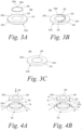
- FIG. 3A illustrates an exploded view of an example corneal implant 200.
- the corneal implant 200 includes corneal tissue 202 extracted from a donor cornea.
- the donor corneal tissue 202 may be sized and shaped with a cutting instrument (e.g., a laser) for transplant into a recipient cornea.
- the donor corneal tissue 202 has an anterior surface 202a and a posterior surface 202b.
- the donor corneal tissue 202 may have a substantially circular perimeter defined by an edge 202c extending between the anterior surface 202a and the posterior surface 202c.
- the substantially circular perimeter of the donor corneal tissue 202 may be approximately 8 mm in diameter.
- the donor corneal tissue 202 may have a perimeter of another shape, e.g., ellipse, polygon, etc.
- a narrow interior channel 204 (i.e., enclosed passageway) is formed in the donor corneal tissue 202 below the anterior surface 202a.
- a femtosecond laser can be focused at a depth below the anterior surface 202a to cut the channel 204 through the donor corneal tissue 202.
- the channel 204 may have a substantially annular shape, i.e., shaped as a thin ring, as shown in FIG. 3A .
- the channel 204 may be centered relative to the anterior surface 202a of the donor corneal tissue 202.
- the corneal implant 200 also includes a supporting structure 206.
- the supporting structure 206 is formed from non-tissue material.
- the supporting structure 206 may be formed from a plastic.
- the supporting structure 206 may be formed from a nickel titanium alloy, also known as Nitinol.
- the supporting structure 206 is substantially annular in shape, i.e., shaped as a thin ring.
- the supporting structure 206 may be approximately 3 mm in diameter.
- the supporting structure 206 may be defined by a narrow piece of material having two ends 206a, b, where the piece of material is curved so that the two ends 206a, b meet on a circle. As such, the annular shape of the supporting structure 206 has a small break between the two ends 206a, b.
- FIG. 3B illustrates an example approach for positioning the supporting structure 206 into the channel 204.
- a small incision 208 may be formed in the corneal tissue 202 to provide access to the channel 204 from the anterior surface 202a.
- the end 206a (or alternatively the end 206b) of the supporting structure 206 may be introduced into the small incision 208, and the supporting structure 206 may be guided (i.e., fed) through the small incision 208 and into the channel 204.
- the supporting structure 206 is sufficiently flexible to be manipulated in the manner shown in FIG. 3B .
- FIG. 3C illustrates an assembled view of the example corneal implant 200.
- the supporting structure 206 is positioned in the channel 204. Formed from plastic, nickel titanium alloy, etc., the supporting structure 206 provides sufficient rigidity to support the donor corneal tissue 202 and to resist deformation of the donor corneal tissue 202. In general, the supporting structure 206 is more rigid than the donor corneal tissue 202, but provides sufficient flexibility for use in the eye 10.
- the channel 204 and the supporting structure 206 have corresponding annular shapes so that the supporting structure 206 can be positioned in the channel 204.
- the channel 204 may have a smaller diameter than the supporting structure 206.
- the supporting structure 206 is 3 mm in diameter
- the channel 204 may be slightly less than 3 mm in diameter.
- the supporting structure 206 pushes against the tissue around the channel 204, which may expand outwardly.
- the donor corneal tissue 202 around the channel 204 applies an inward pressure on the supporting structure 206 to hold the supporting structure 206 more securely in the channel 204.
- the channel 204 and the supporting structure 206 shown in FIGS. 3A-C may have substantially annular shapes, other implementations may employ other shapes, such as an ellipse.
- the supporting structure 206 shown in FIGS. 3A-C may be a single annular structure, the supporting structure 206 may be alternatively defined by a combination of a plurality of sub-structures.
- the supporting structure 206 may be defined by a combination of two half-circle structures that can be received into the channel 204 in a manner similar to a single annular structure.
- 3A-C may illustrate the example corneal implant 200 with one supporting structure 206 positioned in one corresponding channel 204
- other embodiments may include more than one channel 204 receiving one or more respective supporting structures.
- an embodiment may include more than one channel 204 arranged concentrically to receive a respective annular supporting structure 206.
- the additional supporting structures 206 may provide additional stability and resistance to deformation of the donor corneal tissue 202.
- a corneal transplant involves removing diseased/damaged corneal tissue 14 from the eye 10 and correspondingly forming a cavity 16 in the eye 10.
- the corneal implant 200 may be implanted into the eye 10, where the supporting structure provides greater stability for the corneal implant 200 and the recipient cornea 12.
- the cavity 16 also provides a bed for receiving the corneal implant 200.
- the cavity 16 may be further shaped with a cutting instrument (e.g., a laser) to accommodate the size and shape of the corneal implant 100.
- the corneal implant 100 may be further shaped a cutting instrument (e.g., a laser) to accommodate the size and shape of the cavity 16.
- the corneal implant 100 is positioned in the cavity 16 and sutured in place with one or more sutures 18.
- the anterior surface 202a of the donor corneal tissue 202 is aligned with the anterior surface 12a (outwardly facing surface) of the recipient cornea 12 and the posterior surface 202b of the donor corneal tissue 202 is aligned with the posterior portion 12b (interior portion) of the recipient cornea 12.
- the donor corneal tissue 202 and thus the corneal implant 200 may have a diameter of approximately 8 mm and the supporting structure 206 may have a diameter of approximately 3 mm.
- the supporting structure 206 may be positioned in the channel 204 which may be centered relative to the anterior surface 202a of the donor corneal tissue 202.
- the corneal implant 200 When received in the cavity 16, the corneal implant 200 may be centered on the recipient cornea 12, which may for instance be approximately 12 mm in diameter.
- the supporting structure 206 of approximately 3 mm may be centered on the recipient cornea 12.
- the supporting structure 206 provides structural support and stability particularly for the central region of approximately 3 mm which is more critical for vision.
- the one or more sutures 18 may apply forces and/or torques that can deform the shapes of the corneal implant 100 and the recipient cornea 12.
- the supporting structure 206 supports the structures of the corneal implant 100 and the recipient cornea 12 to reduce or minimize the deformation caused by such forces and/or torques.
- the supporting structure 206 enhances the stability of the corneal implant 200 and the recipient cornea 12 and reduces the likelihood of refractive errors after the transplant procedure.
- the sutures 18 can be removed.
- the supporting structure 206 may also be removed after sutures 18 have been removed.
- the supporting structure 206 may be translucent (e.g., a translucent plastic) so that it does not interfere with the light entering the cornea 10 and affect the patient's vision.
- the supporting structure 206 may be opaque and light-absorbing (e.g., dark in color), so that light entering the cornea 10 is not reflected by the supporting structure 206 to create halos or other glare in the patient's vision.
- the supporting structure 206 may be configured to modify the refractive profile of the donor corneal tissue 202.
- the donor corneal tissue 202 defines a refractive profile
- the supporting structure 206 modifies the refractive profile of the donor corneal tissue 202 to provide a desired refractive correction for the recipient cornea 10.
- the supporting structure 206 may be configured to address myopia, hyperopia, and/or astigmatism in the recipient cornea 12.
- the supporting structure 206 may also be configured to apply medication or other drug to the donor corneal tissue 202 and/or the recipient cornea 12.
- medication may promote healing of the recipient cornea and/or prevent infection.
- such medication may reduce the likelihood of rejection of the corneal implant 200.
- the invasion of new blood vessels into the cornea also known as corneal neovascularization, allows host immune effector lymphocytes to access donor antigens more easily and may increase the likelihood of rejection of implants from donor cornea.
- the supporting structure 206 may carry a medication for treating corneal neovascularization.
Landscapes
- Health & Medical Sciences (AREA)
- Engineering & Computer Science (AREA)
- Biomedical Technology (AREA)
- Transplantation (AREA)
- Life Sciences & Earth Sciences (AREA)
- Heart & Thoracic Surgery (AREA)
- Vascular Medicine (AREA)
- Ophthalmology & Optometry (AREA)
- Animal Behavior & Ethology (AREA)
- General Health & Medical Sciences (AREA)
- Public Health (AREA)
- Veterinary Medicine (AREA)
- Cardiology (AREA)
- Oral & Maxillofacial Surgery (AREA)
- Prostheses (AREA)
Description
- The present disclosure pertains to systems and methods for treating disorders of the eye, and more particularly, to systems and methods for transplanting a cornea to treat such disorders.
- Various disorders of the eye may result from diseased/damaged corneal tissue. The diseased/damaged corneal tissue can affect vision by scattering and/or distorting light and causing glare and/or blurred vision. In some cases, proper vision can only be restored by a corneal transplant which replaces the diseased/damaged corneal tissue with healthy tissue from an organ donor. For instance, treatment of keratoconus, a degenerative disorder that causes weakness and abnormal shaping of the cornea, may ultimately require corneal transplant surgery.
-
US-A-8388608 discloses a method for producing a corneal implant, comprising: providing donor corneal tissue extracted from a donor cornea, the donor corneal tissue having an anterior surface and a posterior surface; forming an interior channel in the donor corneal tissue at a depth below the anterior surface, the channel having a channel shape. - Systems and methods of the present disclosure corneal employ corneal transplants to treat eyes with diseased/damaged corneal tissue. Corneal transplant procedures may involve suturing an implant of healthy corneal tissue to a recipient cornea. The sutures and other aspects of the transplant procedure, however, may cause unwanted deformation of the corneal implant and the recipient cornea. Such deformation may cause refractive errors. According to aspects of the present disclosure, a supporting structure may be embedded into the corneal implant to enhance the stability of the corneal implant and the recipient cornea and to reduce the likelihood of unwanted deformation when the corneal implant is sutured to the recipient cornea.
- Disclosed herein (but not being part of the claimed subject matter) is a corneal implant including donor corneal tissue extracted from a donor cornea. The donor corneal tissue has an anterior surface and a posterior surface. The donor corneal tissue includes an interior channel formed at a depth below the anterior surface. The channel has a channel shape. The corneal implant includes a supporting structure formed from non-tissue material and is positioned in the channel. The supporting structure has a supporting-structure shape and provides support to resist deformation of the donor corneal tissue.
- The present invention provides a method for producing a corneal implant including providing donor corneal tissue from a donor cornea. The donor corneal tissue has an anterior surface and a posterior surface. The method includes forming an interior channel in the corneal tissue at a depth below the anterior surface. The channel has a channel shape. The method includes positioning a supporting structure formed from non-tissue material in the channel of the donor corneal tissue. The supporting structure has a supporting-structure shape and provides support to resist deformation of the donor corneal tissue.
- Disclosed herein (but not being part of the claimed subject matter) is a method for transplanting a corneal implant including providing a corneal implant. The corneal implant includes donor corneal tissue extracted from a donor cornea. The corneal tissue has an anterior surface and a posterior surface. The corneal tissue includes an interior channel formed in the donor corneal tissue at a depth below the anterior surface. The channel has a channel shape. The corneal implant includes a supporting structure formed from non-tissue material and positioned in the channel. The supporting structure has a supporting-structure shape and provides support to resist deformation of the donor corneal tissue. The method includes removing unwanted corneal tissue from a recipient cornea and correspondingly forming a cavity in the recipient cornea. The method includes positioning the corneal implant in the cavity. The method includes coupling, with sutures, the corneal implant to the recipient cornea.
-
-
FIG. 1A illustrates a recipient eye with diseased/damaged corneal tissue. -
FIG. 1B illustrates removal of the diseased/damaged corneal tissue from the recipient eye ofFIG. 1A . -
FIG. 1C illustrates positioning of a corneal implant relative to the recipient eye after the diseased/damaged corneal tissue is removed from the recipient eye as illustrated inFIG. 1B . -
FIG. 1D illustrates suturing of the corneal implant in the recipient eye after the corneal implant is positioned relative to the recipient eye as illustrated inFIG. 1C . -
FIG. 2A illustrates an example suture pattern for a corneal transplant. -
FIG. 2B illustrates another example suture pattern for a corneal transplant. -
FIG. 3A illustrates an exploded view of an example corneal implant including donor corneal tissue and a supporting structure, according to aspects of the present disclosure. -
FIG. 3B illustrates an example approach for positioning the supporting structure in the donor corneal tissue ofFIG. 3A , according to aspects of the present disclosure. -
FIG. 3C illustrates an assembled view of the example corneal implant ofFIG. 3A , according to aspects of the present disclosure. -
FIG. 4A illustrates positioning of an example corneal implant relative to a recipient eye after the diseased/damaged corneal tissue is removed from the recipient eye, according to aspects of the present disclosure. -
FIG. 4B illustrates suturing of the example corneal implant in the recipient eye after the corneal implant is positioned relative to the recipient eye as illustrated inFIG. 4A , according to aspects of the present disclosure. - Various disorders of the eye may result from diseased/damaged corneal tissue. The diseased/damaged corneal tissue can affect vision by scattering and/or distorting light and causing glare and/or blurred vision. In some cases, proper vision can only be restored by a corneal transplant which replaces the diseased/damaged corneal tissue with healthy tissue from an organ donor.
-
FIGS. 1A-D illustrate perspective views of an example transplant procedure where acorneal implant 100 from a donor cornea is introduced into aneye 10. As shown inFIG. 1A , theeye 10 includes acornea 12, which has diseased/damagedcorneal tissue 14. Treatment of theeye 10 via corneal transplant involves surgical removal of the diseased/damagedcorneal tissue 14 from theeye 10 as shown inFIG. 1B . The removal of the diseased/damagedcorneal tissue 14 correspondingly produces acavity 16 in thecornea 12. AsFIG. 1C shows, thecavity 16 provides a bed in thecornea 12 for receiving thecorneal implant 100. In some cases, thecavity 16 may be further shaped with a cutting instrument (e.g., a laser) to accommodate the size and shape of thecorneal implant 100. Alternatively or additionally, thecorneal implant 100 may be further shaped with a cutting instrument (e.g., a laser) to accommodate the size and shape of thecavity 16. As shown inFIG. 1D , thecorneal implant 100 is received into thecavity 16 and coupled to therecipient cornea 12 with one ormore sutures 18, e.g., fine nylon suture thread. Once therecipient cornea 12 has healed and fully accepts thecorneal implant 100, thesutures 18 can be removed. -
FIGS. 2A-B illustrate respective top views ofexample patterns 20a, b ofsutures 18 that keep thecorneal implant 100 in place for the transplant. Other implementations, however, are not limited to theexample suture patterns 20a, b shown inFIGS. 2A-B . In theexample pattern 20a, a series ofindividual sutures 18 are arranged along the periphery of thecorneal implant 100, where eachindividual suture 18 passes through therecipient cornea 12 and thecorneal implant 100 to couple thecorneal implant 100 to therecipient cornea 12. In the example pattern 20b, one ormore sutures 18 each pass alternately through therecipient cornea 12 and thecorneal implant 100 along the periphery of thecorneal implant 100 and create a zig-zag pattern between therecipient cornea 12 and thecorneal implant 100. If plurality ofsutures 18 is employed, thesutures 18 may form a plurality of overlapping zig-zag patterns. - Because the
recipient cornea 12 and thecorneal implant 100 are bodies of soft tissue, the forces and/or torques applied by thesutures 18 may deform the shapes of thecorneal implant 100 and therecipient cornea 12. In some cases, other aspects of the transplant procedure may also contribute to the deformations. Such deformations may result in aberrations or other abnormal shaping that affect vision by scattering and/or distorting light travelling through therecipient cornea 12. Patients may require contact lenses or glasses after corneal transplants to correct refractive errors caused by such deformations. - To reduce or minimize unwanted deformation of a corneal implant and the
recipient cornea 12, a supporting structure is embedded into the corneal implant so that the corneal implant can resist the forces and/or torques applied by thesutures 18 and can maintain its desired shape more effectively. Although the supporting structure is embedded in the corneal implant, the supporting structure can also support the structure of therecipient cornea 12. In general, the supporting structure enhances the stability of the corneal implant and the recipient cornea and reduces the likelihood of refractive errors after the corneal implant is transplanted into therecipient cornea 12. -
FIG. 3A illustrates an exploded view of an examplecorneal implant 200. Thecorneal implant 200 includescorneal tissue 202 extracted from a donor cornea. The donorcorneal tissue 202 may be sized and shaped with a cutting instrument (e.g., a laser) for transplant into a recipient cornea. The donorcorneal tissue 202 has ananterior surface 202a and aposterior surface 202b. As shown inFIG. 3A , the donorcorneal tissue 202 may have a substantially circular perimeter defined by anedge 202c extending between theanterior surface 202a and theposterior surface 202c. For instance, the substantially circular perimeter of the donorcorneal tissue 202 may be approximately 8 mm in diameter. In other embodiments, however, the donorcorneal tissue 202 may have a perimeter of another shape, e.g., ellipse, polygon, etc. - A narrow interior channel 204 (i.e., enclosed passageway) is formed in the donor
corneal tissue 202 below theanterior surface 202a. According to one approach, a femtosecond laser can be focused at a depth below theanterior surface 202a to cut thechannel 204 through the donorcorneal tissue 202. Thechannel 204, for instance, may have a substantially annular shape, i.e., shaped as a thin ring, as shown inFIG. 3A . In addition, thechannel 204 may be centered relative to theanterior surface 202a of the donorcorneal tissue 202. - The
corneal implant 200 also includes a supportingstructure 206. The supportingstructure 206 is formed from non-tissue material. For instance, in some embodiments, the supportingstructure 206 may be formed from a plastic. In other embodiments, the supportingstructure 206 may be formed from a nickel titanium alloy, also known as Nitinol. Like thechannel 204, the supportingstructure 206 is substantially annular in shape, i.e., shaped as a thin ring. For instance, the supportingstructure 206 may be approximately 3 mm in diameter. As shown inFIG. 3A , the supportingstructure 206 may be defined by a narrow piece of material having twoends 206a, b, where the piece of material is curved so that the two ends 206a, b meet on a circle. As such, the annular shape of the supportingstructure 206 has a small break between the two ends 206a, b. -
FIG. 3B illustrates an example approach for positioning the supportingstructure 206 into thechannel 204. Asmall incision 208 may be formed in thecorneal tissue 202 to provide access to thechannel 204 from theanterior surface 202a. Theend 206a (or alternatively theend 206b) of the supportingstructure 206 may be introduced into thesmall incision 208, and the supportingstructure 206 may be guided (i.e., fed) through thesmall incision 208 and into thechannel 204. The supportingstructure 206 is sufficiently flexible to be manipulated in the manner shown inFIG. 3B . -
FIG. 3C illustrates an assembled view of the examplecorneal implant 200. In particular, the supportingstructure 206 is positioned in thechannel 204. Formed from plastic, nickel titanium alloy, etc., the supportingstructure 206 provides sufficient rigidity to support the donorcorneal tissue 202 and to resist deformation of the donorcorneal tissue 202. In general, the supportingstructure 206 is more rigid than the donorcorneal tissue 202, but provides sufficient flexibility for use in theeye 10. - As described above, the
channel 204 and the supportingstructure 206 have corresponding annular shapes so that the supportingstructure 206 can be positioned in thechannel 204. In some implementations, however, thechannel 204 may have a smaller diameter than the supportingstructure 206. For instance, if the supportingstructure 206 is 3 mm in diameter, thechannel 204 may be slightly less than 3 mm in diameter. As such, when the supportingstructure 206 is received by thechannel 204, the supportingstructure 206 pushes against the tissue around thechannel 204, which may expand outwardly. Correspondingly, the donorcorneal tissue 202 around thechannel 204 applies an inward pressure on the supportingstructure 206 to hold the supportingstructure 206 more securely in thechannel 204. - Although the
channel 204 and the supportingstructure 206 shown inFIGS. 3A-C may have substantially annular shapes, other implementations may employ other shapes, such as an ellipse. In addition, although the supportingstructure 206 shown inFIGS. 3A-C may be a single annular structure, the supportingstructure 206 may be alternatively defined by a combination of a plurality of sub-structures. For instance, the supportingstructure 206 may be defined by a combination of two half-circle structures that can be received into thechannel 204 in a manner similar to a single annular structure. Furthermore, althoughFIGS. 3A-C may illustrate the examplecorneal implant 200 with one supportingstructure 206 positioned in one correspondingchannel 204, other embodiments may include more than onechannel 204 receiving one or more respective supporting structures. For instance, an embodiment may include more than onechannel 204 arranged concentrically to receive a respectiveannular supporting structure 206. The additional supportingstructures 206 may provide additional stability and resistance to deformation of the donorcorneal tissue 202. - As described above with reference to
FIGS. 1A-B , a corneal transplant involves removing diseased/damagedcorneal tissue 14 from theeye 10 and correspondingly forming acavity 16 in theeye 10. Instead of thecorneal implant 100, however, thecorneal implant 200 may be implanted into theeye 10, where the supporting structure provides greater stability for thecorneal implant 200 and therecipient cornea 12. As shown inFIG. 4A , thecavity 16 also provides a bed for receiving thecorneal implant 200. In some cases, thecavity 16 may be further shaped with a cutting instrument (e.g., a laser) to accommodate the size and shape of thecorneal implant 100. Alternatively or additionally, thecorneal implant 100 may be further shaped a cutting instrument (e.g., a laser) to accommodate the size and shape of thecavity 16. - As shown further in
FIG. 4B , thecorneal implant 100 is positioned in thecavity 16 and sutured in place with one or more sutures 18. When received in thecavity 16, theanterior surface 202a of the donorcorneal tissue 202 is aligned with theanterior surface 12a (outwardly facing surface) of therecipient cornea 12 and theposterior surface 202b of the donorcorneal tissue 202 is aligned with theposterior portion 12b (interior portion) of therecipient cornea 12. - As described above, the donor
corneal tissue 202 and thus thecorneal implant 200 may have a diameter of approximately 8 mm and the supportingstructure 206 may have a diameter of approximately 3 mm. The supportingstructure 206 may be positioned in thechannel 204 which may be centered relative to theanterior surface 202a of the donorcorneal tissue 202. When received in thecavity 16, thecorneal implant 200 may be centered on therecipient cornea 12, which may for instance be approximately 12 mm in diameter. Accordingly, the supportingstructure 206 of approximately 3 mm may be centered on therecipient cornea 12. In this case, the supportingstructure 206 provides structural support and stability particularly for the central region of approximately 3 mm which is more critical for vision. - As described above, the one or
more sutures 18 may apply forces and/or torques that can deform the shapes of thecorneal implant 100 and therecipient cornea 12. The supportingstructure 206, however, supports the structures of thecorneal implant 100 and therecipient cornea 12 to reduce or minimize the deformation caused by such forces and/or torques. In general, the supportingstructure 206 enhances the stability of thecorneal implant 200 and therecipient cornea 12 and reduces the likelihood of refractive errors after the transplant procedure. - Once the
recipient cornea 12 has healed and fully accepts thecorneal implant 200, thesutures 18 can be removed. In some cases, the supportingstructure 206 may also be removed aftersutures 18 have been removed. - In some embodiments, the supporting
structure 206 may be translucent (e.g., a translucent plastic) so that it does not interfere with the light entering thecornea 10 and affect the patient's vision. In other embodiments, the supportingstructure 206 may be opaque and light-absorbing (e.g., dark in color), so that light entering thecornea 10 is not reflected by the supportingstructure 206 to create halos or other glare in the patient's vision. - In addition to supporting the shape of the donor
corneal tissue 202 and therecipient cornea 12, the supportingstructure 206 may be configured to modify the refractive profile of the donorcorneal tissue 202. In other words, the donorcorneal tissue 202 defines a refractive profile, and in response to receiving the supportingstructure 206 into thechannel 204, the supportingstructure 206 modifies the refractive profile of the donorcorneal tissue 202 to provide a desired refractive correction for therecipient cornea 10. For instance, the supportingstructure 206 may be configured to address myopia, hyperopia, and/or astigmatism in therecipient cornea 12. - Furthermore, the supporting
structure 206 may also be configured to apply medication or other drug to the donorcorneal tissue 202 and/or therecipient cornea 12. In some implementations, such medication may promote healing of the recipient cornea and/or prevent infection. In other implementations, such medication may reduce the likelihood of rejection of thecorneal implant 200. For instance, the invasion of new blood vessels into the cornea, also known as corneal neovascularization, allows host immune effector lymphocytes to access donor antigens more easily and may increase the likelihood of rejection of implants from donor cornea. As such, the supportingstructure 206 may carry a medication for treating corneal neovascularization.
Claims (15)
- A method for producing a corneal implant, comprising:providing donor corneal tissue extracted from a donor cornea, the donor corneal tissue having an anterior surface and a posterior surface;forming an interior channel in the donor corneal tissue at a depth below the anterior surface, the channel having a channel shape; andpositioning a supporting structure formed from non-tissue material in the channel of the donor corneal tissue, the supporting structure having a supporting-structure shape and providing support to resist deformation of the donor corneal tissue.
- The method of claim 1, further comprising cutting the donor corneal tissue to have an edge extending between the anterior surface and the posterior surface, the edge defining a substantially circular perimeter for the donor corneal tissue.
- The method of claim 2, wherein the substantially circular perimeter of the corneal tissue is approximately 8 mm in diameter.
- The method of claim 1, wherein the channel shape and the supporting-structure shape are substantially annular.
- The method of claim 4, wherein the supporting structure is approximately 3 mm in diameter.
- The method of claim 3, wherein the channel shape has a smaller diameter than the supporting-structure shape.
- The method of claim 1, wherein the supporting structure is formed from a piece of material having two ends, and positioning the supporting structure in the channel of the donor corneal tissue includes:forming an incision to provide access to the channel from the anterior surface of the donor corneal tissue;introducing one end of the supporting structure through the incision; andguiding the supporting structure through the incision and into the channel.
- The method of claim 1, wherein in response to receiving the supporting structure into the channel, the donor cornea tissue applies an inward pressure on the supporting structure to hold the supporting structure securely in the channel.
- The method of claim 1, further comprising combining a plurality of sub-structures to define the supporting structure.
- The method of claim 1, wherein the supporting structure is formed from a plastic or a nickel titanium alloy.
- The method of claim 1, wherein the supporting structure is formed from a translucent material.
- The method of claim 1, wherein the supporting structure is formed from an opaque, light-absorbing material.
- The method of claim 1, wherein the donor corneal tissue defines a refractive profile, and in response to receiving the supporting structure into the channel, the supporting structure modifies the refractive profile of the donor corneal tissue to provide a desired refractive correction for a cornea receiving the corneal implant.
- The method of claim 1, wherein forming the channel in the corneal tissue includes ablating, with a laser, the corneal tissue.
- The method of claim 1, further comprising applying a drug to the supporting structure.
Applications Claiming Priority (2)
| Application Number | Priority Date | Filing Date | Title |
|---|---|---|---|
| US201762515528P | 2017-06-05 | 2017-06-05 | |
| PCT/US2018/036059 WO2018226695A1 (en) | 2017-06-05 | 2018-06-05 | Systems and methods for corneal transplants |
Publications (4)
| Publication Number | Publication Date |
|---|---|
| EP3634307A1 EP3634307A1 (en) | 2020-04-15 |
| EP3634307A4 EP3634307A4 (en) | 2021-03-10 |
| EP3634307C0 EP3634307C0 (en) | 2024-12-11 |
| EP3634307B1 true EP3634307B1 (en) | 2024-12-11 |
Family
ID=64459109
Family Applications (1)
| Application Number | Title | Priority Date | Filing Date |
|---|---|---|---|
| EP18813963.8A Active EP3634307B1 (en) | 2017-06-05 | 2018-06-05 | Method for corneal transplants |
Country Status (7)
| Country | Link |
|---|---|
| US (2) | US11083565B2 (en) |
| EP (1) | EP3634307B1 (en) |
| JP (2) | JP7368677B2 (en) |
| AU (1) | AU2018282219B2 (en) |
| CA (1) | CA3066215A1 (en) |
| MA (1) | MA52460A (en) |
| WO (1) | WO2018226695A1 (en) |
Families Citing this family (3)
| Publication number | Priority date | Publication date | Assignee | Title |
|---|---|---|---|---|
| US12171652B2 (en) * | 2018-09-14 | 2024-12-24 | Jitander Dudee | Corneal prosthesis and method of penetrating keratoplasty |
| FR3099045B1 (en) * | 2019-07-22 | 2021-07-30 | Univ Jean Monnet Saint Etienne | PROCESS FOR PRODUCING A PLURALITY OF IMPLANTS FROM A HUMAN OR ANIMAL HORNA PREVIOUSLY TAKEN |
| US12533259B1 (en) * | 2025-06-05 | 2026-01-27 | Eye Hospital, Wenzhou Medical University | Methods for implanting corneal inlays based on high-precision visual axis positioning and intraocular pressure adjustment |
Family Cites Families (15)
| Publication number | Priority date | Publication date | Assignee | Title |
|---|---|---|---|---|
| US4772283A (en) * | 1986-05-16 | 1988-09-20 | White Thomas C | Corneal implant |
| CA2168347A1 (en) * | 1993-08-02 | 1995-02-09 | Thomas A. Silvestrini | Segmented preformed intrastromal corneal insert |
| US6197019B1 (en) * | 1994-04-25 | 2001-03-06 | Gholam A. Peyman | Universal implant blank for modifying corneal curvature and methods of modifying corneal curvature therewith |
| US5755785A (en) | 1994-08-12 | 1998-05-26 | The University Of South Florida | Sutureless corneal transplantation method |
| US6544286B1 (en) * | 2000-07-18 | 2003-04-08 | Tissue Engineering Refraction, Inc. | Pre-fabricated corneal tissue lens method of corneal overlay to correct vision |
| US6789544B2 (en) * | 2002-09-20 | 2004-09-14 | Massimo Busin | Modified penetrating keratoplasty method |
| WO2008131973A2 (en) * | 2007-04-26 | 2008-11-06 | Medinnova As | Transplant storage |
| BRPI0702038E2 (en) | 2007-05-30 | 2009-05-12 | Carneiro Adriano Biondi Monteiro | suture-free corneal transplant device |
| EP2926769A1 (en) * | 2008-06-27 | 2015-10-07 | AMO Development, LLC | Intracorneal inlay, system, and method |
| PL221349B1 (en) | 2010-05-04 | 2016-03-31 | Kałużny Bartłomiej Indywidualna Specjalistyczna Praktyka Lekarska | Method and implant for the correction of vision defects |
| PL219627B1 (en) * | 2010-09-08 | 2015-06-30 | Kałużny Bartłomiej Indywidualna Specjalistyczna Praktyka Lekarska | Method for fixing the corneal graft and an implant for fixing the corneal graft |
| US8388608B1 (en) | 2011-10-24 | 2013-03-05 | Indywidualna Specjalistyczna Praktyka Lekarska Dr Med. Bartlomiej Kaluzny | Method and implant for attachment of the transplanted cornea |
| US20140155871A1 (en) * | 2012-05-10 | 2014-06-05 | James Stuart Cumming | Method for preparing corneal donor tissue for refractive eye surgery utilizing the femtosecond laser |
| IL230567A0 (en) | 2014-01-21 | 2014-04-30 | E K D D S Ltd | Method and appartus for improved endothelial implatation |
| US11026778B2 (en) * | 2016-08-24 | 2021-06-08 | Massachusetts Eye And Ear Infirmary | Keratoprosthesis apparatuses, systems, and methods |
-
2018
- 2018-06-05 EP EP18813963.8A patent/EP3634307B1/en active Active
- 2018-06-05 AU AU2018282219A patent/AU2018282219B2/en active Active
- 2018-06-05 JP JP2019566749A patent/JP7368677B2/en active Active
- 2018-06-05 MA MA052460A patent/MA52460A/en unknown
- 2018-06-05 US US16/000,476 patent/US11083565B2/en active Active
- 2018-06-05 WO PCT/US2018/036059 patent/WO2018226695A1/en not_active Ceased
- 2018-06-05 CA CA3066215A patent/CA3066215A1/en active Pending
-
2021
- 2021-07-13 US US17/374,801 patent/US12029642B2/en active Active
-
2023
- 2023-04-19 JP JP2023068462A patent/JP7617164B2/en active Active
Also Published As
| Publication number | Publication date |
|---|---|
| JP7617164B2 (en) | 2025-01-17 |
| AU2018282219A1 (en) | 2019-12-19 |
| JP2020522326A (en) | 2020-07-30 |
| CA3066215A1 (en) | 2018-12-13 |
| EP3634307C0 (en) | 2024-12-11 |
| WO2018226695A1 (en) | 2018-12-13 |
| AU2018282219B2 (en) | 2024-05-02 |
| MA52460A (en) | 2021-03-10 |
| US11083565B2 (en) | 2021-08-10 |
| US20210338415A1 (en) | 2021-11-04 |
| JP7368677B2 (en) | 2023-10-25 |
| EP3634307A1 (en) | 2020-04-15 |
| US12029642B2 (en) | 2024-07-09 |
| EP3634307A4 (en) | 2021-03-10 |
| JP2023083443A (en) | 2023-06-15 |
| US20180344450A1 (en) | 2018-12-06 |
Similar Documents
| Publication | Publication Date | Title |
|---|---|---|
| AU667342B2 (en) | Corneal ring inlay and methods of use | |
| JP7617164B2 (en) | Systems and methods for corneal transplantation | |
| US5196026A (en) | Method of implanting corneal inlay lenses smaller than the optic zone | |
| JP3415838B2 (en) | Vacuum centering guide and dissection device for cornea | |
| JP6495827B2 (en) | Capsule expander device, system, and method for preventing sac turbidity and stabilizing sac | |
| US5133750A (en) | Synthetic sapphire intraocular lens | |
| US4612012A (en) | Corneal implant | |
| KR102463039B1 (en) | Intraocular pseudophakic contact lenses and related systems and methods | |
| US20030014042A1 (en) | Method of creating stromal pockets for corneal implants | |
| WO2007103053A2 (en) | Method of preparing a donor cornea for transplantation | |
| EP3700478A1 (en) | Corneal implant systems and methods | |
| RU2578086C1 (en) | Method of ophthalmic surgical operations using autograft | |
| ES3040568T3 (en) | Corneal implant | |
| US20240238079A1 (en) | Corneal implant with a rigid ring | |
| US11160649B2 (en) | Flexible integral intracorneal ring | |
| GB2629464A (en) | Corneal graft retainer ring |
Legal Events
| Date | Code | Title | Description |
|---|---|---|---|
| STAA | Information on the status of an ep patent application or granted ep patent |
Free format text: STATUS: THE INTERNATIONAL PUBLICATION HAS BEEN MADE |
|
| PUAI | Public reference made under article 153(3) epc to a published international application that has entered the european phase |
Free format text: ORIGINAL CODE: 0009012 |
|
| STAA | Information on the status of an ep patent application or granted ep patent |
Free format text: STATUS: REQUEST FOR EXAMINATION WAS MADE |
|
| 17P | Request for examination filed |
Effective date: 20191227 |
|
| AK | Designated contracting states |
Kind code of ref document: A1 Designated state(s): AL AT BE BG CH CY CZ DE DK EE ES FI FR GB GR HR HU IE IS IT LI LT LU LV MC MK MT NL NO PL PT RO RS SE SI SK SM TR |
|
| AX | Request for extension of the european patent |
Extension state: BA ME |
|
| A4 | Supplementary search report drawn up and despatched |
Effective date: 20210208 |
|
| RIC1 | Information provided on ipc code assigned before grant |
Ipc: A61F 9/00 20060101ALI20210202BHEP Ipc: A61F 2/14 20060101AFI20210202BHEP Ipc: A61F 9/008 20060101ALI20210202BHEP Ipc: A61F 9/013 20060101ALI20210202BHEP Ipc: A61F 2/16 20060101ALI20210202BHEP |
|
| STAA | Information on the status of an ep patent application or granted ep patent |
Free format text: STATUS: EXAMINATION IS IN PROGRESS |
|
| 17Q | First examination report despatched |
Effective date: 20211214 |
|
| GRAP | Despatch of communication of intention to grant a patent |
Free format text: ORIGINAL CODE: EPIDOSNIGR1 |
|
| STAA | Information on the status of an ep patent application or granted ep patent |
Free format text: STATUS: GRANT OF PATENT IS INTENDED |
|
| INTG | Intention to grant announced |
Effective date: 20240704 |
|
| GRAS | Grant fee paid |
Free format text: ORIGINAL CODE: EPIDOSNIGR3 |
|
| GRAA | (expected) grant |
Free format text: ORIGINAL CODE: 0009210 |
|
| STAA | Information on the status of an ep patent application or granted ep patent |
Free format text: STATUS: THE PATENT HAS BEEN GRANTED |
|
| AK | Designated contracting states |
Kind code of ref document: B1 Designated state(s): AL AT BE BG CH CY CZ DE DK EE ES FI FR GB GR HR HU IE IS IT LI LT LU LV MC MK MT NL NO PL PT RO RS SE SI SK SM TR |
|
| REG | Reference to a national code |
Ref country code: GB Ref legal event code: FG4D |
|
| REG | Reference to a national code |
Ref country code: CH Ref legal event code: EP |
|
| REG | Reference to a national code |
Ref country code: DE Ref legal event code: R096 Ref document number: 602018077553 Country of ref document: DE |
|
| REG | Reference to a national code |
Ref country code: IE Ref legal event code: FG4D |
|
| U01 | Request for unitary effect filed |
Effective date: 20241216 |
|
| U07 | Unitary effect registered |
Designated state(s): AT BE BG DE DK EE FI FR IT LT LU LV MT NL PT RO SE SI Effective date: 20250110 |
|
| PG25 | Lapsed in a contracting state [announced via postgrant information from national office to epo] |
Ref country code: HR Free format text: LAPSE BECAUSE OF FAILURE TO SUBMIT A TRANSLATION OF THE DESCRIPTION OR TO PAY THE FEE WITHIN THE PRESCRIBED TIME-LIMIT Effective date: 20241211 |
|
| PG25 | Lapsed in a contracting state [announced via postgrant information from national office to epo] |
Ref country code: ES Free format text: LAPSE BECAUSE OF FAILURE TO SUBMIT A TRANSLATION OF THE DESCRIPTION OR TO PAY THE FEE WITHIN THE PRESCRIBED TIME-LIMIT Effective date: 20241211 |
|
| PG25 | Lapsed in a contracting state [announced via postgrant information from national office to epo] |
Ref country code: NO Free format text: LAPSE BECAUSE OF FAILURE TO SUBMIT A TRANSLATION OF THE DESCRIPTION OR TO PAY THE FEE WITHIN THE PRESCRIBED TIME-LIMIT Effective date: 20250311 |
|
| PG25 | Lapsed in a contracting state [announced via postgrant information from national office to epo] |
Ref country code: GR Free format text: LAPSE BECAUSE OF FAILURE TO SUBMIT A TRANSLATION OF THE DESCRIPTION OR TO PAY THE FEE WITHIN THE PRESCRIBED TIME-LIMIT Effective date: 20250312 |
|
| PG25 | Lapsed in a contracting state [announced via postgrant information from national office to epo] |
Ref country code: RS Free format text: LAPSE BECAUSE OF FAILURE TO SUBMIT A TRANSLATION OF THE DESCRIPTION OR TO PAY THE FEE WITHIN THE PRESCRIBED TIME-LIMIT Effective date: 20250311 |
|
| PG25 | Lapsed in a contracting state [announced via postgrant information from national office to epo] |
Ref country code: SM Free format text: LAPSE BECAUSE OF FAILURE TO SUBMIT A TRANSLATION OF THE DESCRIPTION OR TO PAY THE FEE WITHIN THE PRESCRIBED TIME-LIMIT Effective date: 20241211 |
|
| PG25 | Lapsed in a contracting state [announced via postgrant information from national office to epo] |
Ref country code: PL Free format text: LAPSE BECAUSE OF FAILURE TO SUBMIT A TRANSLATION OF THE DESCRIPTION OR TO PAY THE FEE WITHIN THE PRESCRIBED TIME-LIMIT Effective date: 20241211 |
|
| PG25 | Lapsed in a contracting state [announced via postgrant information from national office to epo] |
Ref country code: IS Free format text: LAPSE BECAUSE OF FAILURE TO SUBMIT A TRANSLATION OF THE DESCRIPTION OR TO PAY THE FEE WITHIN THE PRESCRIBED TIME-LIMIT Effective date: 20250411 |
|
| VS25 | Lapsed in a validation state [announced via postgrant information from nat. office to epo] |
Ref country code: MD Free format text: LAPSE BECAUSE OF FAILURE TO SUBMIT A TRANSLATION OF THE DESCRIPTION OR TO PAY THE FEE WITHIN THE PRESCRIBED TIME-LIMIT Effective date: 20241211 |
|
| PG25 | Lapsed in a contracting state [announced via postgrant information from national office to epo] |
Ref country code: SK Free format text: LAPSE BECAUSE OF FAILURE TO SUBMIT A TRANSLATION OF THE DESCRIPTION OR TO PAY THE FEE WITHIN THE PRESCRIBED TIME-LIMIT Effective date: 20241211 |
|
| PG25 | Lapsed in a contracting state [announced via postgrant information from national office to epo] |
Ref country code: CZ Free format text: LAPSE BECAUSE OF FAILURE TO SUBMIT A TRANSLATION OF THE DESCRIPTION OR TO PAY THE FEE WITHIN THE PRESCRIBED TIME-LIMIT Effective date: 20241211 |
|
| U20 | Renewal fee for the european patent with unitary effect paid |
Year of fee payment: 8 Effective date: 20250628 |
|
| PLBE | No opposition filed within time limit |
Free format text: ORIGINAL CODE: 0009261 |
|
| STAA | Information on the status of an ep patent application or granted ep patent |
Free format text: STATUS: NO OPPOSITION FILED WITHIN TIME LIMIT |
|
| REG | Reference to a national code |
Ref country code: CH Ref legal event code: L10 Free format text: ST27 STATUS EVENT CODE: U-0-0-L10-L00 (AS PROVIDED BY THE NATIONAL OFFICE) Effective date: 20251022 |
|
| 26N | No opposition filed |
Effective date: 20250912 |
|
| REG | Reference to a national code |
Ref country code: CH Ref legal event code: H13 Free format text: ST27 STATUS EVENT CODE: U-0-0-H10-H13 (AS PROVIDED BY THE NATIONAL OFFICE) Effective date: 20260127 |
|
| PG25 | Lapsed in a contracting state [announced via postgrant information from national office to epo] |
Ref country code: MC Free format text: LAPSE BECAUSE OF FAILURE TO SUBMIT A TRANSLATION OF THE DESCRIPTION OR TO PAY THE FEE WITHIN THE PRESCRIBED TIME-LIMIT Effective date: 20241211 |
|
| GBPC | Gb: european patent ceased through non-payment of renewal fee |
Effective date: 20250605 |
|
| PG25 | Lapsed in a contracting state [announced via postgrant information from national office to epo] |
Ref country code: GB Free format text: LAPSE BECAUSE OF NON-PAYMENT OF DUE FEES Effective date: 20250605 |
|
| PG25 | Lapsed in a contracting state [announced via postgrant information from national office to epo] |
Ref country code: IE Free format text: LAPSE BECAUSE OF NON-PAYMENT OF DUE FEES Effective date: 20250605 |
|
| VS25 | Lapsed in a validation state [announced via postgrant information from nat. office to epo] |
Ref country code: MA Free format text: LAPSE BECAUSE OF FAILURE TO SUBMIT A TRANSLATION OF THE DESCRIPTION OR TO PAY THE FEE WITHIN THE PRESCRIBED TIME-LIMIT; INVALID AB INITIO Effective date: 20180605 |
|
| PG25 | Lapsed in a contracting state [announced via postgrant information from national office to epo] |
Ref country code: CH Free format text: LAPSE BECAUSE OF NON-PAYMENT OF DUE FEES Effective date: 20250630 |